1
SQR7080
Service Manual
372 Engine Mechanical System
SQR372 Engine
Service Manual
Chery Automobile Co., Ltd.
Forewords
In order to help the technical servicing personnel to have correct understanding and good command of the
cute Chery Model SQR7080 vehicle, and to master the skills for fast repairs and rational maintenance, a
special edition of the “Chery QQ Technical Service Manual—372 Engine Mechanics Division” is
compiled and published.
This Manual gives a detailed description on the dismounting, installation, checks and tests, adjustments
and diagnoses, technical standards and specifications for adjustments and diagnoses of various parts and
components as well as subsystems of Chery QQ 372 engines. This Manual is published by Chery
Automobile Co., Ltd.
Any parts or sections of this Manual shall not be copied or duplicated in whatever form or by whatever
approach without the written authorization of the publisher.
The right of interpreting the Manual belongs to the Service Department of Chery Automobile Co. Ltd
Editors
March of 2004
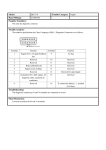
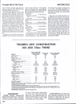
3、Special tools for maintenance:
Outer appearance
S
Code and Name
Purpose
Auxiliary devices for engine
dismounting and checks
Mounting onto engine
dismounting and check
stand
Engine dismounting and check stand
Dismounting and
installing engine
Clockwise belt wheel wrench
Camshaft clockwise
belt wheel dismounting
1
Chery Automobile Co., Ltd
PDF 文件使用 "pdfFactory Pro" 试用版本创建 www.fineprint.com.cn
SQR7080
Service Manual
372 Engine Mechanical System
Spring bush pulling and removing
device
Installing crankshaft
oil seal
Valve locking block removal device
Dismounting and
installation of valve
spring locks
S
Auxiliary tools
Flying wheel
T
fixture
Valve guiding pipe punch
Dismounting and
installation of
crankshaft
Removing and
installation of valve
guiding pipe
Shaft oil seal replacer
Oil seal stand
Outer appearance
screw driver
Code and Name
Purpose
Crankshaft belt wheel fixture
Remove and install
crankshaft belt wheel
Wrench
Remove and install
camshaft slave gear
wheel
Replace valve spacing
adjust washer
2
Chery Automobile Co., Ltd
PDF 文件使用 "pdfFactory Pro" 试用版本创建 www.fineprint.com.cn
SQR7080
Service Manual
372 Engine Mechanical System
Water pump pulley assembly
wrench
water pump Assembly
Measuring Clearance gauge, calipers, Micrometer, ruler, centesimal meter, cylinder gauge ,
tools
pressure meter, torque wrench
Tool
Piston ring dismounting device
Oils
Engine lubricating oil, bond
Chapter 2
Timing Belt Service
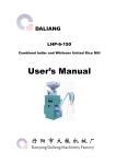
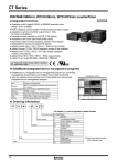
1. Configuration diagram
1 Water pump pulley
2 Timing belt cover
3 Timing belt
4 Torsion shock absorber
5 Timing pulley damper
6 Tensioner
7 Crankshaft timing pulley
※ :Non-reusable part
Unit:N·m(kg·cm)
3
Chery Automobile Co., Ltd
PDF 文件使用 "pdfFactory Pro" 试用版本创建 ÿwww.fineprint.com.cn
SQR7080
Service Manual
372 Engine Mechanical System
Remove torsional vibration damper.
Remove water pump pulley.
Remove the water pump pulley according to the
illustration.
图 29
Remove it with screwdriver and wrench according to
the illustration.
Remove torsional vibration damper
(1) Fix the flywheel and prevent the gear ring from
rotating.
SST
(2) Remove bolt of torsional vibration damper.
4
Chery Automobile Co., Ltd
PDF 文件使用 "pdfFactory Pro" 试用版本创建 ÿwww.fineprint.com.cn
SQR7080
Timing mark
Service Manual
372 Engine Mechanical System
Remove timing cover cap
Torque: 6±1N.m
Remove timing pulley damper
Do“mark” Remove the tensioner
Clockwise (1)Carry out the operation at the upper thrust point
of compression of the first cylinder piston
(2) After removing the timing cover cap, turn the bolt
and rotate the timing gear clockwise with wrench,
align timing mark of camshaft timing gear with the
cam mark of camshaft cover cap;
Attention: You can rotate the engine clockwise only,
after installing the pulley;
Before removal, make a arrow mark on the position of
timing mark, assemble according to original state.
(3) Make sure that the crankshaft timing pulley wheel
mark is aligned with the mark of the oil pump.
Timing mark
(4) Remove the tensioner bolt, and take off the
tensioner
5
Chery Automobile Co., Ltd
PDF 文件使用 "pdfFactory Pro" 试用版本创建 www.fineprint.com.cn
SQR7080
Service Manual
372 Engine Mechanical System
Remove the timing belt.
[Caution] It is absolutely not allowed to use screw
driver or some other sharp-edged tools to remove the
belt.
Attention: Pay attention to the following points while
using timing belt:
- Don’t bend the belt even at a small angle,
otherwise it will result in rope fracture inside the
belt.
- - Service life of belt is short, don’t pollute the belt
with grease and water.
You have no choice but rotate the engine
clockwise after installing the belt.
2.7 Remove the crankshaft timing gear
6
Chery Automobile Co., Ltd
PDF 文件使用 "pdfFactory Pro" 试用版本创建 www.fineprint.com.cn
SQR7080
Service Manual
372 Engine Mechanical System
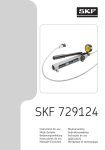
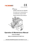
3 Make careful and detailed checks on the timing belt. Replace with new parts if any of the
conditions shown in the figure occurs.
3.1Cracks on the back side rubber;
3.2Cracks of teeth roots, cracks clearing off the fabric lining layer;
3.3Tears and wears of fabric lining layer, missing rear teeth, broken teeth, etc.
Chap
Tears
wears
Chap
3.4 Abnormal tears and wears on belt sides
MIS
Drop-off
Abnormal
of belt core
tears and wears
7
Chery Automobile Co., Ltd
PDF 文件使用 "pdfFactory Pro" 试用版本创建 ÿwww.fineprint.com.cn
and
SQR7080
Service Manual
372 Engine Mechanical System
3.5 Even if the damages on the outer appearance can not be confirmed, the belt should be replaced
under any of the following circumstances:
3.5.1If the water in the water pump is leaked, which makes it necessary to refill the water
continuously;
3.5.2 There are much oil stains on the belt, the belt should be replaced for the rubber will be damaged
when it is expanded;
3.6 Specifications and model of the timing belt
Part number
372-1007081
Belt wide
25.3mm
3.7 Timing belt tensioner
Turn the belt tensioner supporting stand bolts to see if there are any abnormal sound. Check to see if
there are any damages on the contacting surface of the belt.
Specifications and model of the timing belt tensioner
Part number
372-1007030
Wide
27.0mm
Outside diameter
φ50mm
3.8 Check to see if there are any damages on the outer appearance
Specifications and model of clockwise pulley
EF
Model
GL、ZL、GS、ZS
Item
Diameter of camshaft timing
φ110.7+0.1-0.2
gear (mm)
Diameter of crankshaft timing
φ54.65 +0.7-0.13
gear (mm)
3.9 Baffle of crankshaft timing gear
Check to see if there is any deformation
Standard size of crankshaft timing gear:
Wide
28.6mm
8
Chery Automobile Co., Ltd
PDF 文件使用 "pdfFactory Pro" 试用版本创建 www.fineprint.com.cn
SQR7080
Service Manual
372 Engine Mechanical System
4. Installation
4.1 Installation of crankshaft timing gear
Timing mark
4.2 Installation of timing belt
4.2.1 On the upper thrust point of the first cylinder
compression
Place the camshaft timing gear around the front end of
the air exhaust camshaft so as to make the positioning
groove on the gear be aligned with the positioning pin
on the end surface of the camshaft. Then use screws to
fix the clockwise gear, with the torque of 100 ± 5N.m.
4.2.2 Make sure that the punched mark on the
crankshaft clockwise pulley is aligned with the mark
of the oil pump.
Timing mark
Timing mark
4.2.3 Install timing pulley accordingly.
Clockwise
9
Chery Automobile Co., Ltd
PDF 文件使用 "pdfFactory Pro" 试用版本创建 www.fineprint.com.cn
SQR7080
Service Manual
372 Engine Mechanical System
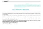
4.3 Install the tensioner
4.3.1 Adjust the tension of the timing belt
①As shown in the figure, make the space between the
edge of the stretching wheel and the water pump case
arc to be about 8mm;
②Tighten the bolt of the stretching wheel with a
torque of 25 ± 3N.m. Use a screwdriver to swing the
stretcher toward the right..
③ Turn the crankshaft for two circles towards the
engine rotating direction, so that the camshaft pulley
and the crankshaft pulley matches the clockwise marks
respectively.
④ Use hands to press down for about 5mm. The force
for pressing the clockwise belt is about: [Reference]
20~30 N
Notice: When the deflection of the timing belt fails to
meet the specifications, the key is to adjust the
above-mentioned stretcher fastening bolt by widening
the spacing.
Tighten the S/A fixing bolt of the stretcher with the
specified torque of 25 ± 3N.m
4 Install the baffle of the crankshaft timing pulley
[Attention] Install the baffle towards the direction
shown in the right figure.
10
Chery Automobile Co., Ltd
PDF 文件使用 "pdfFactory Pro" 试用版本创建 ÿwww.fineprint.com.cn
SQR7080
Service Manual
372 Engine Mechanical System
5 Install the timing cover cap
torque :6±1N.m
6 Install the torsional vibration damper (use SST)
1)、When there is not a flying wheel,
① Fix a part of the crankshaft pulley.
②Pay attention not to make the gear belt moving,
tighten the bolt according to the specified torque :
torque98.0±10N.m{10±1kgm}
2 )
、When there is a flying wheel,
① Fix the flywheel to prevent the tooth ring from
turning
② Then tighten bolt of torsional vibration damper.
11
Chery Automobile Co., Ltd
PDF 文件使用 "pdfFactory Pro" 试用版本创建 ÿwww.fineprint.com.cn
SQR7080
Service Manual
Chapter 3
3-1.Diagram
372 Engine Mechanical System
Camshaft
Service
( Removal and installation order for timing belt)
(1) Valve cage cover
(2) Valve cage cover
gasket
(3) Camshaft
timing
pulley
(4) Camshaft cover
(5) Circular plug
(6) Camshaft bearing
cap
(7) Exhaust camshaft,
(8) Intake camshaft,
(9) Oil seal
(10) Spring retainer
(11) Wave washer
(12) Intake
camshaft
sub-gear
(13) Snap ring
(14) Lock nut
(15) Flange
Non-reusable part
3-2 Removal
①Remove cylinder
head cover assembly
Remove the valve chamber cover cap bolt
from two sides to the centre symmetrically.
②Remove valve chamber cover gasket
2 Routine check of valve
valve clearance standard:
IN
0.18±0.05
Valve
clearance
EX
0.25±0.05
3 Dismount the camshaft clockwise gear
Attention· You must prevent the camshaft from rotating.
12
Chery Automobile Co., Ltd
PDF 文件使用 "pdfFactory Pro" 试用版本创建 ÿwww.fineprint.com.cn
SQR7080
Exhaust
Set bolt
Service Manual
Intake
372 Engine Mechanical System
4 Removal of camshaft cover cap and camshaft
bearing cover
(1) Align the marks on the camshaft gears as shown in
the right figure.
(2)Use bolt to position the master and slave gears on
the air inlet camshaft, as shown in the right figure.
Attention In order to eliminate the radial force, keep the
camshaft in the leveled position before dismounting it
(to avoid possible damages caused by excessive radial
forces)
(3)Remove the bolts in the sequence shown in the
right figure;
Remove the camshaft bearing cover
(4)Remove the spark plug
SST
(5)Remove the camshaft slave gear. Use the special
tool as shown in the right figure.
Clip the camshaft tightly, and turn the gear, to keep
the bite state of master and slave gear; remove the fixing
bolts of slave gear.
Attention Do not damage the surface of the camshaft.
13
Chery Automobile Co., Ltd
PDF 文件使用 "pdfFactory Pro" 试用版本创建 www.fineprint.com.cn
SQR7080
Service Manual
372 Engine Mechanical System
(6) Use tensioning apparatus to remove the bearing use
elastic snap ring, remove wave washer and teethed ring.
3-3 Camshaft
1 Use the caliper to measure the height of the camshaft.
If it is below the specified limits, make proper
replacement.
Camshaft
Unit:mm
EF
Model
ZL、 GL、GS、
Item
RL
ZS
IN
φ23.0-0.02-0.033
EX
φ23.0-0.02-0.033
Standard
IN
φ22.9
EX
φ22.9
2 Checks on camshaft axial clearance
(1)
、When the axial spacing is measured with a clipper
to be larger than the benchmark value, the camshaft is to
be replaced.
Limit
The air inlet camshaft axial clearance is 0.1~0.170mm。
The air exhaust camshaft axial spacing is 0.1 ~
0.173mm。
Limits for operation:0.18mm
3-4 Cleaning
1、Clear off the spark plug carbon accumulation with a
metal brush.
14
Chery Automobile Co., Ltd
PDF 文件使用 "pdfFactory Pro" 试用版本创建 www.fineprint.com.cn
SQR7080
Service Manual
372 Engine Mechanical System
3-5 Installation
① Fix the two φ6 holes of the camshaft gear S/A.
② Turn the slave gear to the right, match the mark hole
on the slave gear with the mark on the master gear, or
align the marks on the slave gear with the mark on the
master gear; then fix the slave gear with bolt.
(thread: M5; pitch: 0.8)
2、Installation of the camshaft
Attention Size of the axial clearance of the camshaft
(1)、Smear lubricating oil at the camshaft gear section
and the cylinder cover axial diameter section.
(2)、Fix the camshaft slave gear by roughly adjusting on
the cylinder cover.
(3) It is necessary to measure the size of axial clearing
of camshaft.
SST
(4)Install camshaft, the timing mark must be aligned
shown as the right figure.
Exhaust
Intake
(5)Smear lubricating oil on the camshaft assembly, the
gears and the cylinder head axial diameter section.
3 Tighten the camshaft bearing cap shown as right
figure.
4 Remove the bolt for fixing the slave gear of the
camshaft assembly.
15
Chery Automobile Co., Ltd
PDF 文件使用 "pdfFactory Pro" 试用版本创建 ÿwww.fineprint.com.cn
SQR7080
Service Manual
372 Engine Mechanical System
SST
5 installation of camshaft head cap
Smear the fluid sealant on the camshaft head cap section
(with oil groove) shown as the right figure.
Sealing line
Tighten the bolts according to the sequences shown as
the right figure with the specified torques.
6 After smearing oil in the plug cap hole and assembling
surface of the plug, use SST to press the plug lid
Attention· Install the plug lid shown as the right
illustration.
Keep unbiased with cylinder head end surface after
pressing.
outside
7 Smear engine oil on the oil seal installation port of
cylinder head, camshaft oil seal edge of blade and
outside ring, use M10 bolt (length 50-60 mm) and SST
press the cylinder, lower 1mm than the end surface of
the cylinder4 head.
Attention ·Under the condition of use the oil seal
repeatedly, press here with engine oil adhesive agent
- The oil seal should not be pressed inclining to one side.
8 Installation of the timing gear of camshaft
After smearing the fluid sealant, use SST to prevent
rotating, tighten the timing gear bolt of camshaft
according to regulated torque of 100±5N.m.
16
Chery Automobile Co., Ltd
PDF 文件使用 "pdfFactory Pro" 试用版本创建 ÿwww.fineprint.com.cn
SQR7080
2.18
2.20
2.22
2.24
2.26
2.28
2.30
2.36
2.34
2.32
2.38
Service Manual
2.40
2.42
2.44
2.46
2.48
2.50
2.52
2.58
2.56
2.54
2.60
2.62
2.64
2.66
2.68
2.70
2.72
2.74
2.80
2.78
2.76
372 Engine Mechanical System
9 Installation of valve chamber cover cap
⑴The used base facing the cylinder cover of the timing
belt cover must be cleaned thoroughly.
⑵Install the new base correctly into the groove of the
valve cage cover cap
⑶Install valve cage cover cap to cylinder head from two
sides to the centre symmetrically according to the
regulated torque of 6±1N.m
1 Use feeler gauge to check the throttle clearance.
Attention· Make sure to measure the clearance between
basic circle of cam and valve adjusting gasket.
Standard of valve clearance :
IN
0.18±0.05
valve
spacing
EX
0.25±0.05
2 When it is beyond the benchmark value, the
adjustment washer has to be replaced and the clearance
should be adjusted.
Attention The valve number that goes beyond the
benchmark value has to be recorded, and the result of
measurements should be recorded as well
(1) Use a caliper to measure and adjust the thickness of
the separation cushion.
(2)Select proper separation cushion on the basis of the
throttle thrusting rod benchmark values.
① IN
Selected cushion thickness = removed cushion
thickness + (measured throttle spacing – 0.18mm)
② EX
Selected cushion thickness = removed cushion
thickness + (measured throttle spacing –
0.25mm)
[Reference] there are 32 kinds of shim is thickness ,
shown as the illustration
17
Chery Automobile Co., Ltd
PDF 文件使用 "pdfFactory Pro" 试用版本创建 www.fineprint.com.cn
SQR7080
Service Manual
Forword
lower
372 Engine Mechanical System
(7) Use the selected adjusting gasket to adjust the
throttle clearance.
Attention Install the feeler with the identification mark
facing downwards.
4. Cylinder head
4-1 Configuration diagram (Do the following operations in the procedures for the dismounting and
installation of the camshaft)
(1)
(2)
(3)
(4)
(5)
(6)
(7)
(8)
(9)
(10)
(11)
(12)
(13)
(14)
Spark plug20±1Nm
Cylinder head
Weather seal I
Cylinder head gasket
Adjust shim
Valve lifter
Keeper
Valve spring seat
Valve spring
Intake valve
Exhaust valve
Valve oil seal
Valve seat
Valve guide
※:Non-reusable part
Unit:N·m(kg·cm)
18
Chery Automobile Co., Ltd
PDF 文件使用 "pdfFactory Pro" 试用版本创建 ÿwww.fineprint.com.cn
SQR7080
Service Manual
372 Engine Mechanical System
4-2 Dismounting
1、Removal of spark plug
2 There are 8 cylinder cover bolts. In the process of removing the
cylinder, please follow the sequences shown as the right
illustration, loosen the bolts one by one evenly and gently.
SST for valve oil seal
3 Removal of the cylinder dustproof sealing and cylinder
cover base.
Attention The cylinder cushion can not be used
repeatedly.
4 Removal of throttle adjusting separation cushion and
valve thrusting rod
5 Use special tools to remove the valve spring locking
block, throttle spring stand, valve spring, IN valve and
EX valve
6 Removal of valve oil seal and valve spring washer
4-3 Clearing
1 The accumulated carbon residue covered on the valve
must be cleared.
2 Use scraper to clear the cylinder cover, the air inlet
and exhaust branching pipe surfaces and bottoms
Attention
Do not damage the cylinder cover surface by scraping
during the process of clearing.
Do not drop filth into the air inlet and the water channel.
19
Chery Automobile Co., Ltd
PDF 文件使用 "pdfFactory Pro" 试用版本创建 ÿwww.fineprint.com.cn
SQR7080
Service Manual
372 Engine Mechanical System
4-4 Routine checks
4-4-1 Cylinder cover
1 Use the straight knife sharp edge ruler to measure the
levelness at various points as shown in the figure.
Cylinder cover 0.10mm
Air inlet branching pipe surface 0.10 mm
2 Use a square ruler to measure the right angle of the
valve spring. Replace the spring if it fails to meet the
specifications.
[Limit] 1.2mm
3 Measure the free state of spring
[Benchmark value] 37mm
Measure outside
diameter
4-4-3 Throttle
Routine checks on throttles
1. Check to see if there are some deformations, obvious
tears and wears
Routine check list on valve
Unit: mm
Item
Standard
Limit
IN
0.85~1.41
___
Wide
E
1.07~1.36
___
X
IN
1.0±0.2
0.75
Width of valve top E
1.0±0.2
0.75
X
Width
20
Chery Automobile Co., Ltd
PDF 文件使用 "pdfFactory Pro" 试用版本创建 ÿwww.fineprint.com.cn
SQR7080
Service Manual
Measure point
Measure point
372 Engine Mechanical System
(2) Checks on the clearance between the throttle guiding
pipe and throttle thrusting rod
1 Use a dial gauge to measure the inner diameter of the
throttle guiding pipe, and use a caliper to measure the
outer diameter.
a) Work out the differences of the measured values. If it
is above the specified limits, the throttle or the guiding
pipe must be replaced.
Attention The measurement points are shown as the
figure. Work out the clearance of the final torn and worn
section
Item
Standard
Limit
Valve guide
inside
φ5.0
___
diameter(mm)
Valve stem
outside diameter
φ5.0
___
(mm)
0.056~
IN
0.07
0.020mm
Spacing
(mm)
0.066~
0.08
EX
0.030mm
(2) Replacement of valve guide
a) Heat the cylinder cover to 80—100 degrees C
with hot water
b) Use special tools to drive in the valve guiding
pipe to the position as shown in the right figure
from the side of the combustion chamber.
Attention The removed guiding pipe cannot be used
repeatedly. The air intake and exhaust valve guiding pipes
should not be mixed up in installation.
c) Use special tools to drive in the new valve
guiding pipe to the position as shown in the
right figure.
Attention In the process of driving in the guiding
pipe into the cylinder cover, the operation should be
carried out slowly until the pipe gets to the proper
position. No excessive driving should be exerted. Pay
attention to the specifications in the operation.
21
Chery Automobile Co., Ltd
PDF 文件使用 "pdfFactory Pro" 试用版本创建 ÿwww.fineprint.com.cn
SQR7080
Service Manual
372 Engine Mechanical System
Model
EF
Item
GL,ZL,RL,GS,ZS
IN
13.71±0.25
Height(mm)
EX
12.11±0.25
Driving in depth of throttle guiding pipe
Use reamer to grind the inner diameter to achieve the
standard value of the clearing.
(3) Valve mating surface
a) Smear thin layer of red lead powder on the valve
mating surface. Do not turn the valve, and gently
drive it in. Check the mating condition and the
width of mating line.
Correction of valve base stand ring
Attention Signs of breaking or cracking should not
appear on the correction surface. Take it out slowly after
the correction is completed.
1、Use a 45 degree cone as the mating benchmark value.
2、Check the mating position of the throttle. If it is in the
center of the valve, the position is the best one. If not,
proper corrections have to be made.
3、Make conic cutting at the center of the mating position
with 70 degrees toward inwards and 30 degrees outwards.
22
Chery Automobile Co., Ltd
PDF 文件使用 "pdfFactory Pro" 试用版本创建 www.fineprint.com.cn
SQR7080
Service Manual
372 Engine Mechanical System
4 Use polishing agent to grind and polish the throttle
sealing.
Spark plug
insulator
Sub stool
valve
Oil sealing
Spring bottom
plate
Mark
4-5 Assemble of cylinder head
4-5-1 Cylinder head
Pay attention to the following instructions in the
process of assembling for the other accessories on the
cylinder cover.
(1) Spark plug insulator
1 Put the spark plug insulator in the corresponding hole
on the cylinder head with special use auxiliary tools,
smear fluid sealant before pressing, pressing height is
shown as the illustration:
Attention· Pay attention that the vertical degree of its
pressing depth and the cylinder head top surface;
· The insulator should not be deformed while being
pressed; otherwise, it is easy for the valve chamber cover
cap to lea
4-6 Installation
1. Installation of valve spring washer and valve oil
sealing
(1) Cover auxiliary tools on the valve rod head, smear
oil on the outer circle of the auxiliary roundness and
inside of new valve oil seal, install it on the illustrated
position, pull out the auxiliary tools of valve oil seal.
[Reference] Insert the oil sealing up to the dimension as
shown in the right figure.
2 Installation of IN and EX
3 Assembling of valve springs
Attention It is for you to distinguish the different
suppliers by means of paintings on the valve spring, valve
spring of same engine should have the same identification
paint marking.
23
Chery Automobile Co., Ltd
PDF 文件使用 "pdfFactory Pro" 试用版本创建 ÿwww.fineprint.com.cn
SQR7080
Service Manual
Apply oil position
372 Engine Mechanical System
4 Install the locking blocks for the valve spring stands.
Warning
·Protective eye glasses must be worn in the process of this
operation to protect the eyes.
·Beware of the flying spring and other objects
Upon completion of the installation of the throttle
springs and throttle spring stands, use special tools to
install the locking blocks for the throttle spring stands.
5 Installation of the throttle thrusting rod and throttle
spacing by adjusting the separation cushions
6 Install the cylinder cover base, make identification of
the marks for the front and rear directions.
7 Assembling of dustproof sealing strip and cylinder
cover
a) Apply lubricating oil at the threads and grooves of
the bolts.
b) The tightening of the cylinder bolts should follow
the sequence as shown in the right figure. The
tightening is to be carried out in 2—3 operations till
the torque meets the specifications. The torque for the
first tightening operation is 30±2N.m; the torque for
the second tightening operation is 50±3N.m; and the
torque for the third tightening operation is 70±3.5
Nm.
[Torque] 70±3.5Nm
. ①Installation of the spark plug
[Torque] 20±1Nm
Attention: The tools should be placed vertically, so as
not to make the spark plug insulator become deformed,
otherwise it is easy to leak oil.
24
Chery Automobile Co., Ltd
PDF 文件使用 "pdfFactory Pro" 试用版本创建 ÿwww.fineprint.com.cn
SQR7080 Service Manual
372 Engine Mechanical System
5. Water pump
5-1 Configuration diagram (the dismounting and assembling of the cylinder body should be done in the
following procedures)
1“O” ring, non-reusable
2 Oil pump body
3 Weather seal
Non-reusable part
5-2 Dismounting
1. Dismounting and removal of O-shaped ring
Attention These rings are not reusable.
2. Removing the three bolts and dismount the water
pump principal body.
3 Removal of the dustproof sealing stripe
5-3 Clearing
1 .Clearing of the mating surface of the water pump
5-4 Routine checks
1 .Check to see if there are any deformation or
damages
2.Use a hand wrench to see if the turning is OK, and if
it is smoothly lubricated?
5-5 Installation
1 Install the dustproof sealing stripes
2 Install the water pump principal body
Tighten with a torque of 25±1.5N.m
2 Install the new O-rings
25
Chery Automobile Co., Ltd
PDF 文件使用 "pdfFactory Pro" 试用版本创建 ÿwww.fineprint.com.cn
SQR7080 Service Manual
372 Engine Mechanical System
6. Oil pump
6-1 Configuration diagram (The dismounting and installation of the lubricating oil pump should be
carried out according to the following procedures).
①
②
③
④
⑤
⑥
Oil pan,tighten bolt:8±2 Nm
Oil strainer
Oil collector gasket
Oil pump
Oil pump gasket
Rear oil seal bracket
Non-reusable part
6-2 Dismounting
1 The engine being turned upside down on the
dismounting frame, take off the bolts.
26
Chery Automobile Co., Ltd
PDF 文件使用 "pdfFactory Pro" 试用版本创建 ÿwww.fineprint.com.cn
SQR7080
Service Manual
372 Engine Mechanical System
2 Remove the oil pan from the cylinder body.
Attention Do not make the oil pan flange section to be
deformed.
3
4
5
Remove the oil collecting filter and its flange
Attention The filter flange is not reusable.
Dismount the oil pump assembly and oil pump
cushion
Dismounting of oil seal stand
27
Chery Automobile Co., Ltd
PDF 文件使用 "pdfFactory Pro" 试用版本创建 ÿwww.fineprint.com.cn
SQR7080
Service Manual
372 Engine Mechanical System
6-3 Clearing
1.For the mating surfaces of the oil bottom case, oil
pump and oil seal stands,
2. For the mating surfaces of the rear oil seal stand and
oil pump
scraper and chipping chisel or some other tools may be
used to clear the used ones.
Attention Do not drop the residues into the cylinder
body.
6-4 Disintegration and assembling of oil pump
6-4-1 Configuration diagram
1 Weather seal
2 Oil pump cover plate
3 Driven rotor
4 Drive rotor
5 Split pin
6 Relief valve spring seat
7 Relief valve spring
8 Relief valve
9 Crankshaft front oil sealing
10 Oil pump body
※:Non-reusable part
28
Chery Automobile Co., Ltd
PDF 文件使用 "pdfFactory Pro" 试用版本创建 ÿwww.fineprint.com.cn
SQR7080
Service Manual
372 Engine Mechanical System
6-4-2 Disintegration
1.Weather seal
Attention The weather seal are not reusable.
2 Remove the oil pump cover
Attention: The bolt is assembled with glue, loosen it with
screw driver according to the illustrations
3 Remove the driven and drive rotor of the oil pump
4.Take off the split pin
Attention The split pins are not reusable.
Attention: Pay attention not to make the spring and spring
seat sending forth and dropping suddenly, while taking
off the open pins.
pressure
卸压阀
relief valve
slider
滑块
pressure relief
valve
卸压阀弹簧
Spring seat
弹簧座
5.Removal of the oil pump pressure relief valve spring
stand, spiral spring, oil pump pressure relief valve
6. Removal of the front oil seal of the crankshaft
Attention The removed oil seals are not reusable.
29
Chery Automobile Co., Ltd
PDF 文件使用 "pdfFactory Pro" 试用版本创建 ÿwww.fineprint.com.cn
SQR7080
Service Manual
Mark
标记
372 Engine Mechanical System
6-4-3 Routine checks
(1) Checks on lubricating oil pump spacing
1. Follow the mark on the interior and exterior gears of
the oil pump to place it into the lubricating oil pump
body on the cylinder body.
2. Use a feeler to measure the clearance between the
interior gear and the exterior gear
[Benchmark] 0.05-0.18mm(average of 9 points)
[Limit] 0.35 mm
1. Use a feeler to measure the clearance between the
rotator and the pump body
[Benchmark] 0.10-0.181mm
[Limit]
0.25mm
(2) Routine checks on the pressure relief valve
1 Remove the pressure relief valve, there should be no
visible tears, wears and scrapes on the pressure relief
valve
6-4-4
1 After smearing lubricating oil on the lips of the new
T-shaped oil seals, use SST to make the assembly.
SST
Pressing
direction
Inside
Attention
·Use new oil seal..
·The exposed part of the outer edge of the oil seal after
being pressed in should be less than 0.5mm.
Oil sealing
油封露出
out5mm
5mm以下
30
Chery Automobile Co., Ltd
PDF 文件使用 "pdfFactory Pro" 试用版本创建 ÿwww.fineprint.com.cn
SQR7080
Service Manual
372 Engine Mechanical System
2. Assembling of the oil pump pressure relief valve and
split pins
Attention The split pins are not reusable.
Mark
标识
3. The marks of the exterior and interior gears of the
lubricating oil pump should be on the visible side when
being assembled into the pump body.
4 The new weather seal should be put inside the oil pump
cover groove.
6-5 Disintegratin and assembling of oil seal
6-5-1 Configuration diagram
Non-reusable part
31
Chery Automobile Co., Ltd
PDF 文件使用 "pdfFactory Pro" 试用版本创建 ÿwww.fineprint.com.cn
SQR7080
Service Manual
372 Engine Mechanical System
-5-2 Disintegration
1. Use a flat screwdriver to remove the rear oil seal.
Attention The oil seals are not reusable.
Oil sealing
lip
6-5-3 Checks
Check to see if the tears and wears of the lip section of
the oil seals are within the normal conditions, and if
there are any damages in outer appearance.
6-5-4 Assembling
Smear lubricating oil on the new oil seal lip section.
2. Install the oil seal shown as the right figure.
6-6 Assembling
1. Assembling of the oil sealing stands
(1) Smear oil sealing silica on the oil sealing
stands shown as the right figure.
[Grease] Letai 5699
Attention The liquid sealing silica is to be smeared to
the mating section of the oil seal stands and cylinder
body surface, with a width of 3—4mm.
[Torque] 25±1.5N.m
32
Chery Automobile Co., Ltd
PDF 文件使用 "pdfFactory Pro" 试用版本创建 ÿwww.fineprint.com.cn
SQR7080
Service Manual
372 Engine Mechanical System
2. Assembling of new oil pump washer, oil pump
assembly
[Torque] 20±1.5N.m
3. Installation of new lubricating oil collecting and
filtering device, oil pump collecting and filtering
device
[Torque] 6±1N.m
4.Assembling of oil pan
(1) Clear the mating surface with the cylinder
body
(2) Apply sealing silica before assembling
[Grease] Letai 5699
Attention
·The liquid cushion with silica line diameter of
ф3-4mm, without any broken section
·Make the assembly in 15 minutes after the
application of silica
(3). Tighten in the sequence shown in the right
figure with the torque of 6±1N.m from the centre to
the two sides
front
front
Rear
rear
33
Chery Automobile Co., Ltd
PDF 文件使用 "pdfFactory Pro" 试用版本创建 ÿwww.fineprint.com.cn
SQR7080
Service Manual
372 Engine Mechanical System
7. Crankshaft connecting rod mechanism
7-1 Configuration diagram (Dismount and assemble the oil pump in the follow sequence)
(1) Connecting rod cover
(2) Connecting rod bearing bush
(3) Piston and connecting rod assembly
(4) Main bearing cover
(5) Crankshaft
(6) Crankshaft bush
(7) Thrust washer
(8) Cylinder block
(9) No.1 compression ring
(10) No.2 compression ring
(11) Oil ring
(12) Piston
(13) Connecting rod
(14) Piston pin
Non-reusable part
34
Chery Automobile Co., Ltd
PDF 文件使用 "pdfFactory Pro" 试用版本创建 ÿwww.fineprint.com.cn
SQR7080
Service Manual
372 Engine Mechanical System
7-2 Disintegration of crankshaft connecting rod
mechanism
1、Check the connecting rod axial clearance
(1) Use centimeter or feeler to measure axial
spacing
[Benchmark]:0.15-0.24mm
[Limit]:0.30mm
2、Check the connecting rod bush vertical clearance
(2)Remove the bush cover
Attention: Parts and components of various
cylinders should be placed in good order.
(1) Clean the bush and axle diameter
(4) Place clearance gauge on the connecting bearing
diameter.
(5) Tighten bush cover according to regulated torque
torque: 40±2N.m
Attention Do not turn the crankshaft
(6) Remove the bush cover, measure the maximum
width of the spacing ruler
[Benchmark]: 0.020-0.044 mm
[Limit]: 0.07 mm
35
Chery Automobile Co., Ltd
PDF 文件使用 "pdfFactory Pro" 试用版本创建 www.fineprint.com.cn
SQR7080
Connecting
rod bush
Service Manual
372 Engine Mechanical System
(6) Replace the bush if width is beyond the limit.
Attention:
·In replacing the bushes, you should use the products
of same brand and from the same manufacturer, which
can accord with the request of clearings.
3. Removal of connecting rod bearing cover and
connecting rod bush
Connecting
rod cover
(1) The threaded section of the connecting rod bolt is
to be equipped with protective sleeve to prevent from
scraping the cylinder hoe and crankshaft connecting
rod axle diameter. Then knock the piston connecting
rod out with the handle of a hammer.
Attention Put the parts and components of various
cylinders in good order.
Lagging cover
protective sleeve
(2) Use a caliper to measure the crankshaft axial
clearance. If the axial clearance is above the limits, it
is needed to replace the axial thrust washer or the
crankshaft.
[Benchmark]:0.089-0.211mm
[Limit]:0.30mm
Benchmark
Item
value
Thickness of thrust
1.9 +0.11-0.03
face
36
Chery Automobile Co., Ltd
PDF 文件使用 "pdfFactory Pro" 试用版本创建 ÿwww.fineprint.com.cn
SQR7080
Service Manual
372 Engine Mechanical System
4 Remove the main bush of the crankshaft, the
crankshaft, the crankshaft bush, and the axial thrust
plate of crankshaft
Check the radial clearance of the crankshaft
(1) Remove the crankshaft bearing cover; use a resin
hammer to knock the bearing cover off gently.
(2) Clean the inside of the bushes, the inside of the
bearing cover, the cylinder walls, the axle diameter,
etc. Make thorough checks for any tears and wears as
well as other damages.
(3) Use a clearance+6 gauge to adjust the radial
clearance of the crankshaft; tighten the bolts of
bearing bush cover with specified torque. [Torque]
70±3.5N.m
Attention Tighten the bolts of the crankshaft bearing
cover in three times to the regulated value, in the
sequence as shown in the right figure.
Attention: Don’t turn the crankshaft after
tightening ,because of the clearance gauge.
37
Chery Automobile Co., Ltd
PDF 文件使用 "pdfFactory Pro" 试用版本创建 www.fineprint.com.cn
SQR7080
Service Manual
Mark
372 Engine Mechanical System
(4) Remove the bearing cover and measure the
maximum width of the spacing. If it goes beyond the
limit, replace the bush.
[Benchmark]:0.025-0.069mm
[Limit]:0.10mm
5 Disassembling of connecting rod assembly of the
piston
(1). Use the piston ring pliers to remove the primary
ring, the secondary ring and the oil ring
Attention Do not mix up the pistons and piston rings
for each unit of assembly.
(2). Use SST to remove the piston, connecting rod and
piston pin
① Remove the piston pin to take off the piston and the
connecting rod by using SST.
7-3 Clearing
7-3-1 Cylinder body
Warning Wear eye glasses during the clearing
operation to protect your eyes.
1. Use flat chisel to clear the cylinder body, the
cylinder cover, the oil bottom casing, the oil pump and
the oil seal.
7-3-2 Piston
Warning
Wear eye glassed in the process of
cleaning to protect your eyes.
1. Use the old ring to clean the accumulated carbon in
the ring groove.
2. Clean the accumulated carbon at various parts with
detergents.
Attention Do not use metal brush or some other hard
substance to do the cleaning.
38
Chery Automobile Co., Ltd
PDF 文件使用 "pdfFactory Pro" 试用版本创建 ÿwww.fineprint.com.cn
SQR7080
Service Manual
Top dead
center
Bottom dead
center
372 Engine Mechanical System
7-4 Routine checks
7-4-1 Cylinder block
1. Checks on the levelness of cylinder top surface
(1). Use a ruler and feeler to do the measurements of
the six parts as shown in the right figure.
[Limit]
0.08mm
2. The use of cylinder meter: Measure the values at the
parts as shown in the right figure and work out the
maximum value and the minimum value. Replace the
cylinder body or do the boring of the cylinder if the
values exceed the limits.
[Limit] 0.03mm
[ Reference] Circularity:A-B or a-b
Cylindricity:A-a or B-b
[Reference] Cylinder standard diameter:
φ72.00-72.01mm
7-4-2 Piston
1. Check the clearance between the piston pinholes.
(1) Use a caliper to measure the positions of the piston shown in the following figure, with the
maximum value as the size of the piston pin diameter.
(2) Use the inner diameter centimeter to measure the positions of the piston hole diameter shown as
the following figure, take the minimum value as the size of the pinhole diameter.
39
Chery Automobile Co., Ltd
PDF 文件使用 "pdfFactory Pro" 试用版本创建 ÿwww.fineprint.com.cn
SQR7080
Service Manual
372 Engine Mechanical System
(3) Work out the clearance on the basis of the size difference between the hole diameter and the
pin diameter. Replace the piston pin or the piston if the result exceeds the benchmark value.
[Benchmark] 0.004-0.009mm
[Limit]
0.015mm
1. Measurement of the piston diameter
(1) Make the measurement at the position 11mm
below the piston skirt and along the vertical direction
of the piston pin.
[Benchmark] φ72 –0.013–0.025
2. Check the clearance between the piston ring and
the ring groove
(1) Use a feeler to measure the rings
Benchmark
Limit (mm)
(mm)
Primary ring
0.03~0.06
0.12
Secondary
0.03~0.06
0.11
ring
3. Check the clearance of piston ring ends
(1) Put the piston ring in the position which is 45
mm under the cylinder hole top surface, in order to
make the piston ring keep flattened, you can press
the piston ring with piston top surface, then use a
piston gauge to measure the open clearance.
Benchmark
Limit (mm)
(mm)
Primary ring
0.25-0.40
0.65
Secondary
0.35~0.50
0.65
ring
Oil ring
0.20~0.70
1.00
40
Chery Automobile Co., Ltd
PDF 文件使用 "pdfFactory Pro" 试用版本创建 www.fineprint.com.cn
SQR7080
Service Manual
372 Engine Mechanical System
7-4-3 Check the clearance between the piston and the
cylinder wall
1. The positions for measuring the inner diameter of
the cylinder and the piston skirt are as shown in the
right figure. Replace and repair the piston or the
cylinder body, or bore the cylinder if the measured
results exceed the limits
[Benchmark] 0.018~0.03
[Limit] 0.10
[Reference] The clearance between the piston and the
cylinder hole is subject to the innermost diameter of
cylinder in vertical direction minus the maximum
outer diameter of the piston.
2.After the replacement of the piston or the cylinder
body, it is needed to confirm the clearance of the
replaced cylinder once again.
Datum: 0.018~0.030
7-4-4 Crankshaft
1. Check the coaxiality of the main shaft diameter
(1) Use the centimeter to measure the coaxiality.
Replace the crankshaft if the measurement result
exceeds t he limit.
[Limit] 0.03mm
Attention: The bending value should be 1/2 of the
fluctuation for one circle of turning the crankshaft.
2. Check the tears and wears of the crankshaft
(1)Use a caliper to measure the shaft diameter , and
work out the circularity and cylindricity.
[Limit]
0.005mm
(2)Use a caliper to measure the connecting rod
diameter ,and work out the circularity and cylindricity.
[Limit]
0.004mm
the measuring position is shown as the figure,
41
Chery Automobile Co., Ltd
PDF 文件使用 "pdfFactory Pro" 试用版本创建 www.fineprint.com.cn
SQR7080
Service Manual
372 Engine Mechanical System
7-4-5Assmbling of the crankshaft connecting rod
mechanism
1. Assembly of the piston and connecting rod
( 1 ) Use special tools to assemble the piston,
connecting rod and piston pin in the following
specified procedures.
① Smear lubricating oil to the connecting rod pin
hole, and make the assembly according to the marks
for the same unit and in the indicated direction.
Frontward mark
② Make the installation shown as the right figure.
From up to
down:
No.1 ring
No.2 ring
Oil ring
③ Make adjustments and installation of the piston and
the connecting rod shown as the right figure.
④ After smearing lubricating oil to the piston pin, use
pressurizing device to assemble the piston and the
connecting rod.
Attention
· Pay attention to the assembling direction when
pressing in the piston pin;
Ÿ The small bit of connecting rod should be heated to
300℃ while pressing the piston pin in the piston.
Ÿ Exert pressure in the process of pressing by
assuring the alignment of the pin.
(2)Side face with marks should be upright, install
steel belt assembly oil ring (gasket ring, down scraper
and upper scraper),then install the secondary ring, then
install the primary ring
Open degree of every ring is shown as the illustration:
Ring open angle: Down scraping
下刮片
No.1 ring
No.2 ring
Gasket
Up
Up scraping
42
Chery Automobile Co., Ltd
PDF 文件使用 "pdfFactory Pro" 试用版本创建 ÿwww.fineprint.com.cn
SQR7080
Service Manual
372 Engine Mechanical System
3 The crankshaft main bearing cover. Assemble the
crankshaft, shaft bush, shaft body and thruster
according to the following instructions.
(1)The protruding thrust block on the bush should
match the groove on the cylinder body for installation..
Attention Use the bush made by the same
manufacturer.
Outward
Apply oil
(2)Smear lubricating oil on this side (upper side) of
the crankshaft before installing it.
The side thrust chip with oil sink should face
outward (crankshaft handle) for installation on the
cylinder body bearing stand.
Attention Smear lubricating oil on the side of the oil
sink.
( 3 ) Smear lubricating oil on the friction side
opposite to the contact of the bush lower parts. Install
the parts according to the forward induction mark on
the crankshaft bearing cover.
(4)After applying the lubricating oil, tighten the
bolts in the sequence shown as the right figure for
2—3 cycles with the specified torque.
[Torque]
70±3.5N.m
(5) Rotate the crankshaft after assembling, you
should rotate it with ease, the torque should be less
than 1Nm
Attention:· The torque of crankshaft rotating should
be less than 1Nm;(The torque is for installing the
crankshaft only, not for installing the piston connecting
rod)
43
Chery Automobile Co., Ltd
PDF 文件使用 "pdfFactory Pro" 试用版本创建 www.fineprint.com.cn
SQR7080
Service Manual
372 Engine Mechanical System
4. Assemble the piston connecting rod Ay, connecting
rod bush and connecting rod bearing cover according
to the following instructions.
(1)The openings of the air ring and oil ring should
match the specified direction.
(2)Use nylon sleeves for the bolts of the connecting
rod to prevent from scraping the cylinder hole and
axial diameter
( 3 ) Apply lubricating oil to the piston I, the
connecting rod and the surfaces of the other related
moving parts.
Nylon bar
Frontward
(4)Make sure the frontward indication mark on the
piston. Should be frontward and assemble the piston
connecting rod Ay with SST.
Attention The cylinder number on the piston
connecting rod Ay should be identical to the cylinder
number.
(5)Assemble the connecting rod bearing cover and
bush according to the following instructions.
① Smear a little lubricating oil on the bolt and screw
nut stand before they are mounted according to the
indication mark.
② Tighten the left and right screw nuts alternately for
a couple of times with the specified torque.
[Torque]: 40±2N.m
Attention The connecting rod and the rod bush should
be bought from the same supplier.
44
Chery Automobile Co., Ltd
PDF 文件使用 "pdfFactory Pro" 试用版本创建 www.fineprint.com.cn