1
© Photometrix, Australia
http://www.photometrix.com.au
Last updated: July 2013
Users Manual for
Camera Calibrator V1.5
This manual comprises three main sections along with two appendices:
PART A - Quick Reference:
A listing and brief description of all Camera Calibrator
menus, toolbar buttons, cursors and hotkey functions.
PART B – Software overview:
An explanation of how Camera Calibrator performs camera
calibration from digital images, with details about the various
functions and features of the software.
PART C – Recommended operating procedures:
How to set up the coded targets and capture suitable imagery
for camera calibration.
APPENDIX 1 – Camera Calibrator installation note.
APPENDIX 2 – The End-User License Agreement.
PART A
Quick Reference
Provided here is a quick reference to the Camera Calibrator menus, toolbar buttons, cursors,
hotkeys, as well as image and 3D view functions. A detailed explanation of how to use the
software is presented in Part B.
A1. Main screen - menus and toolbar Buttons
A2. Pull-down menus
FILE MENU
- New project
- Open project
- Close project
- Save project
- Save project (under
another name)
- Most recent Camera
Calibrator projects
- Exit program
PROCESS MENU
- Import images (for
calibration)
- View camera calibration
parameters
- Access image scan
settings for automatic
calibration
- Run the automatic
camera calibration
- View the results in 3D**
- Edit/Review image
measurements**
- Create a PDF report**
HELP MENU
-
List of hotkeys
About
** - These options are available after camera calibration has been performed.
2
A3. Toolbar buttons
- Import images for camera calibration.
- Access image scan settings (for open image or first image).
- Perform automatic camera calibration.
- View results in 3D
- View summary of results and create PDF report
A4. Cursors
- Select Cursor: used for ‘select’ functions such as highlighting, marquee
dragging, etc. Default cursor, or invoked via the Ctrl key.
- Navigate Cursor: used for zooming in/out or panning within an image (left
click & drag); invoked via the keyboard Space Bar.
- Cursor for point marking/positional adjustment in Edit/Review Mode. Tip of
blue pencil is used to mark or move feature point in an image. Not required for
fully automatic measurement (targets are centroided and should not be moved)
A5. Hotkeys for Image Handling (select via Help menu)
3
A6. Hotkeys for Image Measurement (select via Help menu)
A7. Hotkeys for 3D View (select via Help menu or
toolbar button)
A8. Zooming/Panning in an Image
The four zoom options available in the active image window are:
The wheel of the mouse can be used to zoom in and out.
The Z (or Y) key. When the pencil cursor is over the point of interest, hold down the Z
key to generate a zoom window. The cursor can then be accurately placed on the feature
point of interest. The window will remain open as long as the Z (or Y) key is held down.
The ALT zoom. Press the ALT key and use the left mouse button to draw a marquee
box that will enclose the enlarged portion of the image. The image will be zoomed upon
release of the mouse button.
4
The ‘+’ keyboard key to enlarge the image and the ‘-’ key to reduce it.
To ‘pan’ or roam within an enlarged (zoomed-in) image, hold down the wheel of the mouse and
move the mouse. The slider bars can also be used for this function, as can dragging the mouse
with left-button held down in Navigate mode (accessed by holding down the space bar).
A9. 3D View Functions
To zoom in or out within the 3D view (make sure the cursor is over the window), the
wheel of the mouse can be used.
To rotate the 3D View about the axis coming out of the screen, hold down the CTRL key
and the right mouse button and move the mouse.
To pan in the 3D View, hold the SHIFT key and the right mouse button and move the
mouse.
To bring a point to the centre of the 3D View display window, first highlight the point
(left mouse button and drag) and then hit the space bar.
Moving the mouse with the right button pressed, and the point mentioned in the previous
dot-point still highlighted, rotates the display about the highlighted point. Also, the
rotations described in the second dot-point will be about the highlighted point.
To centre the network in the 3D View, use the F key.
An Image can be opened from the 3D View by double clicking the corresponding camera
A10. Tool-tip Display for Image Thumbnails
By hovering the mouse cursor over image thumbnails, an enlarged version of the image is shown.
5
PART B Software Overview
B1.
Introduction to Camera Calibration
Photogrammetric measurement is both accurate and reliable, but in order to realize maximum
accuracy, the camera or cameras employed must be calibrated. A full explanation of the motive
behind camera calibration is given in Fraser, C.S., 1997. “Digital Camera Self-Calibration”.
ISPRS International Journal of Photogrammetry and Remote Sensing, Vol. 52, pp. 149-159.
This paper is online: http://www.photometrix.com.au/ Digital_Camera_Self_Calibration.pdf
A brief description of each of the 10 parameters of camera calibration is now given.
Focal Length (c) and Principal Point (xp & yp)
This focal length and the principal point offsets indicate how far the optical axis of the lens is
displaced from the centre of the image formal. The ‘focal length’ actually refers to the
Principal Distance, which changes with focusing. The nominal lens focal length usually
relates to infinity focus. Also, with zoom cameras, this focal length value can vary
dramatically, but Camera Calibrator seeks one value for the camera used in the survey. This
is why it is important not to change zoom or focus during the photographic session.
Generally xp & yp are close to zero (e.g. 0.5mm or less).
Radial Distortion (K1, K2 & K3)
The three parameters K1, K2 & K3 describe the radial lens distortion of the camera lens.
Radial distortion can reach significant levels in digital camera lenses and it needs to be
corrected when computing 3D feature point position to even modest accuracy levels. Radial
distortion also varies with focusing which is a further reason not to alter focus or zoom
within a measurement network.
Decentering Distortion (P1 & P2)
The parameters P1 & P2 express the effect of the decentering of optical elements within the
lens assembly. This error source is generally quite small and can typically be ignored in all
but very high accuracy applications.
Linear Distortion (B1 & B2)
These parameters, B1 & B2, effectively model any relative error in the specified pixel size.
Thus, they can usually be set ‘fixed’ to zero and ignored.
After capturing imagery for calibration (discussed in Part C), there are five main steps to
operating the Camera Calibrator software. Each step has one tool bar button, and each should be
completed in order.
.
6
B2.
Importing Project Images & Associated Camera options
When commencing a new Camera Calibrator project, press the
button on the toolbar.
Alternatively select Process | Import Images from the pull down menu. This initiates a dialog
for the importing of images into the project. This procedure should be followed:
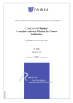
The ‘Image Browser’ dialog for importing images will appear (see below). Select the folder
that contains the images. An image in the Select Image(s) list is transferred into the project
by first highlighting the image or images and then selecting the ‘>’ button. The ‘>>’ button
moves all images into the project. Similarly, the ‘<’ button moves highlighted images out of
the project list, and ‘<<’ removes all images.
Images are
selected by
highlighting
‘thumbnails’
Figure B3
A single image at a time can be selected, or multiple images can be highlighted by using the
mouse and dragging. Holding down the SHIFT key means all images between two selected
images will be highlighted, and the ‘>’ button can then be used.
Press OK when all the appropriate images have been selected for importing into the project
(i.e. they appear in the right-hand-side list).
An up-to-date list of most digital cameras and their key metric design characteristics is provided
with the Camera Calibrator software. From time-to-time, an updated version of this database is
made available for download from:
http://www.photometrix.com.au/downloads/globalcameras.dat
Simply download & save this file, then replace the globalcameras.dat for the Camera Calibrator
(in the ‘cameras’ subdirectory, underneath where the ‘CameraCalibrator.exe’ file is installed).
Camera Calibrator supports JPEG (*.jpg) images which are suitable for calibration. When JPEG
images are imported into the project, the program automatically reads the camera type from the
‘exif’ file header. Thus, the operator does not have to identify the camera or cameras used in the
project.
7
If the image files do not contain information which identifies the camera(s), a warning message
is displayed, as indicated below. This means that before the importing of images into the project,
camera data must be entered either manually. A valid (non-zero) entry must be made for the
focal length, but it need only be a rough estimate of the true value. The image pixel size (mm) is
the only critical value that must be entered. Entering the wrong pixel size introduces a scaling
effect, which is compensated by the computed focal length. Unknown image pixel sizes can be
calculated as a function of the physical CCD dimension and image resolution.
See http://www.photometrix.com.au/images/CCD_sensor_sizes.gif
The default pixel size is set to 0.005mm. A typical range for consumer digital cameras is
0.002mm to 0.009mm, and it is desirable – though not mandatory – to enter the correct value
here if it is known. Adoption of the default pixel size will lead to satisfactory camera calibration
results. Once the required entries are made, click OK to save the camera data. This camera will
then be added to the camera database, so it is available next time.
The camera calibration parameters of focal length, principal point offset and lens distortion vary
with focus and zoom settings for a lens. The possibility arises that multiple sets of calibration
data might be needed if the camera is employed either at different lens focus, or with different
lenses or zoom settings, or if different examples of the same camera model are to be calibrated.
This can create difficulties because the same camera name, etc. will be read from the EXIF
header in the images, but the essential calibration data, which may or may not be known for the
particular lens and focus, will be different to that stored for that camera in the database. Camera
Calibrator overcomes this problem by assigning ‘unique identifiers’ (Unique IDs) to given
camera/lens/focus combinations. The procedure for assigning a Unique ID, which is essentially a
new entry for an existing camera in the database, is simply to type the Unique ID in to the
Camera Parameters dialog, which is opened by double-clicking on the Project Camera icon, then
press OK.
8
B3.
Image Scan Settings
Part two of the five-part process to automatic camera calibration in Camera Calibrator involves
setting up the appropriate image scan settings, so that the software can automatically identify and
measure the coded targets in each image. Press the
button on the toolbar. Alternatively select
Process | Image Scan Settings from the pull down menu. This opens the first image in the
project (or is bound to the currently open image) and initiates the image scan settings dialog, as
below.
At this stage, Camera Calibrator has an option to automatically detect the type of coded targets
used, and to adjust the scan settings accordingly. Simply press the ‘Optimize!’ button and wait a
few moments while the software processes the image, then a message will appear, for example:
If these settings are appropriate, press OK and go on to B4. If not, the settings can be adjusted
manually, by choosing a pixel brightness threshold (typically about 10 is a good value, to
separate the target dot from the background); minimum number of rays for each point to be
deemed value (typically 4 is a good value); and the type of coded target material used. By leftclicking on a coded target in the image, the current settings will be applied to the image-chip in
the dialog, giving an indication as to whether they would be acceptable for the overall process.
Click ‘Overview’ to zoom the image-chip out and operate on a large portion of the image. Once
the scan settings have been selected, press OK.
9
B4.
Automatic Camera Calibration (Autocal)
Once the image scan settings have been selected, Camera Calibrator has enough information to
perform the calibration.
A list of the initial camera parameters can be generated in the main window by double-clicking
on the camera icon (see below). Caution must be exercised in altering camera calibration values.
If nothing is known of these, other than the approximate focal length value (which must always
be entered), the lens distortion parameters K1, K2, K3, P1, P2, B1 & B2 should be left at either
their previously calibrated values, or at zero. The latter four values will rarely be other than zero
(and fixed) for all practical purposes as indicated below.
By default in Camera Calibrator, the settings B1, B2, P1 & P2 are zero and fixed which locks the
value to zero in any calibration. Except in the cases of either prior comprehensive calibration or
in extremely strong network geometries designed for high accuracy measurement, these
parameters can generally be left at zero and fixed, or at their ‘calibrated values’ from the
comprehensive camera calibration process. In cases where the highest possible accuracy is
sought for both the calibration and subsequent 3D measurements, un-tick the boxes for P1 & P2
before running a calibration. This action, however, will rarely lead to significant accuracy
improvements. Also B1 & B2 can be un-ticked, but this should only be contemplated in the very
rare cases where it is known that the digital camera has rectangular pixels. Click OK.
10
The automatic calibration procedure can now be run. Select the
button on the toolbar.
Alternatively select Process | Run Autocal from the pull down menu. If the images have already
been scanned, click ‘Run Self-Calibration’. A warning message may be presented for example if
there is no roll-angle diversity in the camera station network, which means that all images in the
network considered were recorded in ‘landscape’ mode (i.e. normal camera rotation, as indicated
by the small ‘buttons’ on the camera icons in the 3D view). Self-calibration ideally needs at least
one ‘rolled’ image. The following dialog (below left) will be presented, where the process is
initiated by pressing ‘Begin’.
After pressing ‘Begin’, Camera Calibrator will open and scan each image one-by-one, then
perform the automatic camera calibration routine and display the results in the same dialog, as
above (right). This process may take several minutes to complete, after which the calibration is
complete. Press ‘Accept’, and then analyse the results.
B5.
Results
The outcome of the automatic calibration routine performed by Camera Calibrator is the
generation of new camera parameters, as shown in above (right), where the new calibration data
is listed alongside the old. Measures of a successful camera self-calibration can be seen in the
‘Quality of Self-Calibration’ field, where an accuracy value along with an indicator of the
calibration quality (good, average or poor) is shown. The ‘Estimated accuracy of referencing’
value should always be 0.5 pixels or smaller, with a commonly encountered value being around
0.1-0.25 for off-the-shelf consumer digital cameras.
Radial and decentering distortion curves and grids can be plotted by choosing ‘Distortion
Curves’ / ‘Distortion Grids’ in the camera parameters dialog. Example results are shown below:
11
By far the easiest way to verify the results of a calibration is to view the resulting
photogrammetric network in 3D. Any mistakes will be obvious, for example if the points in the
network do not logically represent the calibration measurement scene. Select the
button on
the toolbar. Alternatively select Process | View 3D from the pull down menu. This will open the
3D view. Controls for the 3D view are explained in Part A.
B6.
Summary of Results and PDF Report Creation
Another handy tool to verify the success of the calibration is to view a summary of results. Select
the
button on the toolbar. Alternatively select Process | Create Report from the pull down
menu. The following dialog will appear:
The information presented in this dialog is self-explanatory (or already explained). Press ‘Create
Report’ to export the results in structured 3-page .PDF format, ready for distribution or filing.
12
PART C – Recommended operating procedures:
C1.
Basic Photography Rules
There are four basic rules which apply to recording images for photogrammetric camera
calibration with Camera Calibrator:
The camera lens should not be refocused during the photography session;
The lens zoom should not be adjusted during the photography session;
If the camera has an ‘auto rotate’ function, which digitally rotates the recorded image, the
function must be turned OFF;
The imagery should be captured on the highest possible resolution (i.e. image size) and
highest quality. For example, a 10 megapixel camera should record 10 megapixel images
at the highest quality JPEG setting.
If retro-reflective targets are to be used, the camera will obviously require a flash. If the flash is
too bright & its intensity cannot be controlled, sometimes taping a small piece of paper over the
flash will have the desired effect (or double-thickness paper, etc).
C2.
Camera Setup and Target Layout for Automatic Camera Calibration
The fully automatic camera calibration procedure using Camera Calibrator employs coded
targets and self-calibration. A set of coded targets is provided with the software license. In order
to carry out the automatic camera calibration via Camera Calibrator, the user requires only:
A set of at least 12 different coded targets (also called ‘codes’).
A space of about 3 x 3m on which to position the codes. This will form the target range,
which will be photographed from a camera-to-object distance of from, say, 3-6m,
depending on the lens focal length and field of view. It is desirable to incorporate some
13
3D distribution within the target point array, so all points do not lie in a perfect plane.
Two examples are shown below; one using the wall and one using the floor.
In setting up the target field, keep in mind the following:
Shape of the target array. It is preferable for the target field to have ‘depth’, for example
one or more of the 12 coded targets being out of the plane by 10-20 cm or more. A target
array with some 3D distribution is better than a planar array.
The camera-to-object distance. The size of the target field will depend upon the distance
from which images are to be taken. To determine this, first set the camera at the focus and
zoom setting that you intend to use for subsequent photogrammetric measurement, as it is
critical to calibrate the camera at the same zoom/focus that will be normally be employed.
Typically, the focus will be set to infinity and the zoom at one of its ‘hard stops’, usually
zoomed fully out (widest field of view). Once these settings are made the operator can
balance the requirements of imaging distance versus target field dimensions. Note that in
determining the distance, the sharpness of focus in the images is not of great importance.
An accurate calibration can be performed with slightly defocused images, which might
arise from the camera being set to infinity focus but then being used over a distance of
only 3m or so.
Both target array stability and fixed focus are very important. The targets are not allowed
to move at all. If the camera has a manual focus or focus lock, it is very useful to set this
and then leave it set for the subsequent 3D measurement projects. Also, attention needs to
be given to lighting, with well-exposed images displaying optimal colour saturation or
underexposure being required, depending on the coded target material being used.
An ideal image network geometry for camera calibration is shown below. The
convergence angle (horizontal) between the outer two rays should be 70˚ to 100˚ (it is also
very desirable to have such convergence in both directions).
Note the use of orthogonal roll angles for the camera; three images are in ‘landscape’
orientation, and three in ‘portrait’. It is absolutely critical that this 90˚ variation of roll
angle is present. It is not important which images are rolled 90˚, but several should be.
14
C3.
Other recommendations
Camera calibration should be performed periodically using Camera Calibrator, say every few
months for normal digital cameras, or more often if the camera is accidentally dropped or it is
used in a relatively rough environment.
15
Appendix 1: Camera Calibrator Installation Note
The default installation of the Camera Calibrator executable, camera database files and
documentation will be to the folder C:\Program Files\CameraCalibrator.
In C: Program Files (x86)\CameraCalibrator there will be two folders, as shown:
Cameras: This holds the camera information and associated image chips of cameras within the
database. You will not need to access this folder (unless updating the globalcameras.dat).
Docs: This holds the Users Manual
16
Appendix 2: CAMERA CALIBRATOR END-USER LICENCE AGREEMENT
Warning:
Permission to use the software
Camera Calibrator, including any associated
media, printed materials, and "online" or
electronic
documentation
(collectively,
"Photometrix Products"), is conditional upon
you, the customer (either an individual or a
single entity) ("Licensee"), agreeing to the terms
set out below.
By installing, copying, or
otherwise using the Photometrix Product
Camera Calibrator, you agree to be bound by the
terms of this Agreement. If you do not agree to
the terms of this Agreement, do not install or use
Camera Calibrator; you may, however, return
Camera Calibrator to your supplier for a refund.
This document is a legal agreement
("Agreement") between you and Photometrix
Pty Ltd (ACN 105 272 562) ("Photometrix").
Acceptance shall bind you and all of your
employees, sub-contractors and other agents to
the terms of this Agreement and of the Licence
described below.
PHOTOMETRIX PRODUCTS LICENCE
The Photometrix Product Camera Calibrator is
protected by copyright laws and international
copyright treaties in addition to other
intellectual property laws and treaties. The
Photometrix Product Camera Calibrator is
licensed, not sold.
Pursuant to this Agreement, the Licensee acquires a
non-exclusive right to ("the Licence"):
at any one time use one copy of Camera
Calibrator on a single computer;
DOCUMENTATION
This Licence extends to any enclosed or related
documentation. The documentation may not be
copied, modified or used in any way not
contemplated or expressly authorised by this
Agreement.
LICENSEE’S OBLIGATIONS
The Licensee hereby undertakes the following
obligations:
to not copy, reproduce, lend, rent, lease, sell,
translate, adapt, vary or modify Camera
Calibrator without the express consent of
Photometrix, except as expressly authorised by
this Agreement;
to supervise and control the use of Camera
Calibrator in accordance with the terms of this
Agreement and the Licence;
to ensure its employees, sub-contractors and other
agents who have authorised access to Camera
Calibrator are made aware of the terms of this
Agreement;
to not provide or otherwise make available Camera
Calibrator in any form to any person other
than those referred to in paragraph 00 without
the written consent of Photometrix; and
WARRANTY
The
Licensee acknowledges that Camera
Calibrator cannot be guaranteed error free and
further acknowledges that the existence of any
such errors shall not constitute a breach of this
Agreement or the Licence.
make one copy for backup purposes only; and
use Camera Calibrator strictly in accordance
with the provisions of this Agreement.
If the Licensee wishes to use Camera Calibrator on
more than one computer at the same time, it
may purchase an additional dongle key from
Photometrix, or its licensed distributor, and
such use will be subject to and governed by the
terms of this Agreement.
LICENCE FEE
The Licensee is not entitled to use Camera
Calibrator until the agreed licence fee has been
paid. In the case of payment by cheque, payment
will not be deemed received until the cheque has
been cleared. A separate licence fee is payable in
the circumstances described in clause 0.
Photometrix will replace any defective media at no
charge, subject to notification of the said defect
within 90 days of the date of the
commencement of this Licence and provided
that the Licensee is responsible for all shipping
costs associated with the replacement exercise.
In the event any statute implies terms into this
Agreement which cannot be lawfully excluded,
such terms will apply to this Agreement, save
that the liability of Photometrix for breach of
any such implied term will be limited, at the
option of Photometrix, to any one or more of
the following:
the replacement of goods to which the breach
relates or the supply of equivalent
goods; or
the payment of the cost of replacing the goods
or of acquiring equivalent goods.
17
Photometrix will not be liable for any indirect or
consequential damages arising out of a breach
of this Agreement or the Licence, or arising out
of the supply of defective Photometrix
Products.
if the Licensee, being a firm or partnership, is
dissolved; or
The Licensee acknowledges that it has exercised its
independent judgment in acquiring Camera
Calibrator and has not relied on any
representation made by Photometrix which has
not been stated expressly in this Agreement or
upon any descriptions or illustrations or
specifications contained in any document
including catalogues or publicity material
produced by Photometrix or a licensed reseller
of Photometrix.
Upon termination, the Licensee or its
representatives shall destroy any remaining
copies
of
Camera
Calibrator
and
documentation or otherwise return or dispose
of such material in the manner directed by
Photometrix. Termination pursuant to this
clause shall not affect any rights or remedies
which Photometrix may have otherwise under
this Agreement or at law.
if the Licensee destroys the Photometrix
Products and documentation for any
reason.
ASSIGNMENT
COPYRIGHT
The
Licensee acknowledges that Camera
Calibrator and any associated documentation
are the subject of copyright. The Licensee
shall not during or any time after the expiry or
termination of this Agreement permit any act
which infringes that copyright and, without
limiting the generality of the foregoing, the
Licensee specifically acknowledges that it may
not copy the Photometrix Products except as
otherwise expressly authorised by this
Agreement.
The documentation may not be copied unless
written consent has first been obtained form
Photometrix.
Additional copies of the
associated documentation may be acquired
from Photometrix.
The Licensee shall indemnify Photometrix fully
against all liabilities, costs and expenses which
Photometrix may incur to a third party as a
result of the Licensee’s breach of the copyright
provisions of this Agreement.
TERM OF LICENCE
The Licence commences upon payment of the
licence fee and is granted in perpetuity, but
may be terminated in the following
circumstances:
if the Licensee is in breach of any term of this
Agreement;
if the Licensee, being a corporation, is wound
up, has a receiver (or receiver and
manager) appointed to any of its
property, has a voluntary administrator
or provisional liquidator appointed to it,
or enters into a deed of company
arrangement;
The benefit of this Agreement shall not be dealt
with in any way by the Licensee (whether by
assignment, sub-licensing or otherwise) without
Photometrix’s written consent.
WAIVER
Failure or neglect by either party to enforce at any
time any of the provisions of this Agreement shall
not be construed or deemed to be a waiver of that
party’s rights under the Licence and this Agreement.
GOVERNING LAW
This Agreement takes effect, is governed by and
shall be construed in accordance with the laws of
the state of Victoria, Australia and each party
hereby unconditionally submits to the jurisdiction
of the courts of Victoria and of any court competent
to hear appeals therefrom.
SUPPORT SERVICES
Photometrix may provide the Licensee with
technical support services related to Camera
Calibrator ("Support Services"). Use of Support
Services is governed by the Photometrix policies
and programs described in the documentation
accompanying Camera Calibrator and/or in other
Photometrix provided materials. Any supplemental
software code provided to the Licensee as part of
the Support Services shall be considered part of the
Photometrix Products and subject to the terms and
conditions of this Agreement. With respect to
technical information you provide to Photometrix
as part of the Support Services, Photometrix may
use such information for its business purposes,
including for product support and development.
Photometrix will not utilise such technical
information in a form that personally identifies you.
18