1
STT 3000 Smart Temperature
Transmitter
Model STT35F
Operator Manual
EN1I-6196
Issue 8
September 2010
ii
STT35F Smart Temperature Transmitter Manual
TABLE OF CONTENTS
1.
STT35F DESCRIPTION .......................................................................................................................... 1
1.1
1.2
1.3
1.4
1.5
2.
INSTALLATION OVERVIEW ................................................................................................................ 13
2.1
2.2
2.3
3.
Introduction .................................................................................................................................. 25
Mounting Variations ..................................................................................................................... 26
Surface Mounting Explosionproof Housing.................................................................................. 27
Pipe Mounting Explosionproof Housing....................................................................................... 29
Thermowell Mounting Explosionproof Housing ........................................................................... 31
DIN Rail Mounting ........................................................................................................................ 32
Wiring STT35F Transmitter.......................................................................................................... 33
External Lightning Protection ....................................................................................................... 47
Internal Surge Protection ............................................................................................................. 48
Power Up Transmitter .................................................................................................................. 50
TRANSMITTER CONFIGURATION...................................................................................................... 51
6.1
6.2
6.3
6.4
6.5
6.6
6.7
6.8
6.9
6.10
7.
Introduction .................................................................................................................................. 21
Considerations for STT35F Transmitter ...................................................................................... 22
Considerations for Local Meter Option ........................................................................................ 24
TRANSMITTER INSTALLATION.......................................................................................................... 25
5.1
5.2
5.3
5.4
5.5
5.6
5.7
5.8
5.9
5.10
6.
Introduction .................................................................................................................................. 17
Off-line Bench check .................................................................................................................... 18
Mode of Measurement Considerations........................................................................................ 20
PRE-INSTALLATION CONSIDERATIONS .......................................................................................... 21
4.1
4.2
4.3
5.
Introduction .................................................................................................................................. 13
Installation Components .............................................................................................................. 14
Installation/Operation Tasks ........................................................................................................ 16
OFF-LINE CONFIGURATION (OPTIONAL)............................................................................................. 17
3.1
3.2
3.3
4.
Introduction .................................................................................................................................... 1
STT35F Smart Transmitter ............................................................................................................ 2
Fieldbus Overview.......................................................................................................................... 6
Transmitter Order........................................................................................................................... 9
Local Meter Option....................................................................................................................... 10
Introduction .................................................................................................................................. 51
STT35F Communications ............................................................................................................ 52
Transmitter Configuration Process .............................................................................................. 53
Device Configuration.................................................................................................................... 54
Setting Write Protect Feature....................................................................................................... 55
Simulation Jumper ....................................................................................................................... 57
Establishing Communications...................................................................................................... 58
Making Initial Checks ................................................................................................................... 59
Function Block Application Process............................................................................................. 60
Configuration Tasks ..................................................................................................................... 63
OPERATION.......................................................................................................................................... 65
7.1
7.2
7.3
7.4
7.5
Introduction .................................................................................................................................. 65
Operation Tasks........................................................................................................................... 66
Operation Considerations ............................................................................................................ 67
Monitoring Local Smart Meter Display ......................................................................................... 69
Changing Local Smart Meter Display .......................................................................................... 72
STT35F Smart Temperature Transmitter Manual
iii
8.
CONFIGURATION DESCRIPTION....................................................................................................... 73
8.1
8.2
8.3
8.4
8.5
8.6
8.7
8.8
8.9
8.10
8.11
8.12
8.13
8.14
8.15
8.16
8.17
8.18
8.19
9.
Introduction .................................................................................................................................. 73
Function Block Application Process (FBAP)................................................................................ 74
Block Description ......................................................................................................................... 75
Resource Block ............................................................................................................................ 78
Transducer Block ......................................................................................................................... 81
Analog Input Function Block ........................................................................................................ 86
PID Function Block....................................................................................................................... 94
Block Parameter Summary ........................................................................................................ 101
Link Objects ............................................................................................................................... 108
View Objects .............................................................................................................................. 109
Alert Objects............................................................................................................................... 115
Alarm and Event Reporting........................................................................................................ 116
Trend Objects............................................................................................................................. 117
Domain Objects.......................................................................................................................... 118
Device Description (DD) ............................................................................................................ 118
Object Dictionary (OD) ............................................................................................................... 120
Management Virtual Field Device (VFD) ................................................................................... 124
System Management (SM) ........................................................................................................ 125
Network Management................................................................................................................ 131
MAINTENANCE AND TROUBLESHOOTING.................................................................................... 133
9.1
9.2
9.3
9.4
9.5
9.6
9.7
9.8
9.9
9.10
9.11
9.12
Introduction ................................................................................................................................ 133
Maintaining Transmitters............................................................................................................ 134
Troubleshooting Overview ......................................................................................................... 134
Device Troubleshooting ............................................................................................................. 135
Transmitter Faults ...................................................................................................................... 141
Non-Critical Fault Summary....................................................................................................... 146
Critical Fault Summary............................................................................................................... 147
Device Diagnostics..................................................................................................................... 148
Block Configuration Errors ......................................................................................................... 151
Clearing Block Configuration Errors .......................................................................................... 154
Code Download.......................................................................................................................... 156
Simulation Mode ........................................................................................................................ 158
10. PARTS LIST ........................................................................................................................................ 161
10.1
Replacement Parts..................................................................................................................... 161
11. APPENDIX A ....................................................................................................................................... 163
11.1
11.2
External Wiring Diagram ............................................................................................................ 163
FISCO Concept.......................................................................................................................... 163
CE CONFORMITY (EUROPE) NOTICE .................................................................................................................XIV
iv
STT35F Smart Temperature Transmitter Manual
FIGURES
FIGURE 1-1 TYPICAL STT35F SMART TEMPERATURE TRANSMITTER ...................................................................2
FIGURE 1-2 STT35F BLOCK DIAGRAM WITH I/O PHASE IDENTIFICATION ..............................................................3
FIGURE 1-3 MOUNTING APPROACHES FOR STT35F TRANSMITTER .....................................................................5
FIGURE 1-4 FIELDBUS CONNECTING CONTROL ROOM AND FIELD DEVICES ..........................................................6
FIGURE 1-5 FIELDBUS DEVICES CONTAIN DEVICE APPLICATIONS AND FUNCTION BLOCKS ..................................8
FIGURE 1-6 TYPICAL STT35F TRANSMITTER ORDER COMPONENTS ....................................................................9
FIGURE 1-7 LOCAL METER FACEPLATE ............................................................................................................10
FIGURE 1-8 STT35F WITH LOCAL METER OPTION ............................................................................................11
FIGURE 2-1
FIELDBUS NETWORK COMPONENTS ...........................................................................................15
FIGURE 3-1 BENCH CHECK SETUP FIGURE .......................................................................................................18
FIGURE 4-1 TYPICAL MOUNTING AREA CONSIDERATIONS PRIOR TO INSTALLATION .............................................22
FIGURE 5-1 TYPICAL EXPLOSIONPROOF HOUSING AND DIN RAIL-MOUNTED INSTALLATIONS ...............................26
FIGURE 5-2 SURFACE MOUNTING DIMENSIONS .................................................................................................28
FIGURE 5-3 PIPE MOUNTING DIMENSIONS ........................................................................................................30
FIGURE 5-4 SECURING HOUSING TO THERMOWELL ...........................................................................................31
FIGURE 5-5 DIN RAIL MOUNTING DIMENSIONS .................................................................................................32
FIGURE 5-6 DAISY-CHAIN WIRING SCHEME ......................................................................................................34
FIGURE 5-7 BUS WITH SPURS WIRING ..............................................................................................................35
FIGURE 5-8 FIELDBUS NETWORK USING TREE WIRING SCHEME ........................................................................35
FIGURE 5-9 SINGLE THERMOCOUPLE OR MILLIVOLT SOURCE INPUT WIRING CONNECTIONS ................................40
FIGURE 5-10
TWO THERMOCOUPLES FOR REDUNDANT OPERATION OR DIFFERENTIAL MEASUREMENT INPUT
WIRING CONNECTIONS. ..............................................................................................................................41
FIGURE 5-11A SINGLE RTD OR OHMS SOURCE INPUT WIRING CONNECTIONS ...................................................42
FIGURE 5-12
TYPICAL OUTPUT/POWER WIRING CONNECTIONS WITHOUT METER OR WITH LOCAL METER ........45
FIGURE 5-13
GROUND CONNECTION WITH TRANSIENT PROTECTOR ................................................................46
FIGURE 5-14
MOUNTING OF THE HW48 ON A TRANSMITTER ............................................................................49
FIGURE 6-1 WRITE PROTECT JUMPER LOCATION ON THE TRANSMITTER’S TERMINAL BLOCK ................................56
THERE IS A SECOND JUMPER ALSO ON THE TRANSMITTER’S TERMINAL BLOCK WHICH IS USED FOR DEBUGGING
COMMUNICATION PROBLEMS INDEPENDENT OF SENSOR FUNCTION. SEE FIGURE 6-1. ....................................57
FIGURE 7-1 SMART METER DISPLAY ................................................................................................................69
FIGURE 8-1
FBAP BLOCK DIAGRAM ............................................................................................................76
FIGURE 8-2
TRANSDUCER BLOCK DIAGRAM .................................................................................................82
FIGURE 8-3
ANALOG INPUT BLOCK DIAGRAM................................................................................................89
FIGURE 8-4
PID CONTROL BLOCK DIAGRAM ................................................................................................97
FIGURE 9-1 SIMULATION JUMPER LOCATION ON TERMINAL BLOCK ...................................................................158
FIGURE 10-1
STT EXPLODED PARTS ...........................................................................................................162
STT35F Smart Temperature Transmitter Manual
v
TABLES
TABLE 1-1
TABLE 2-1
TABLE 2-2
TABLE 3-1
TABLE 3-2
TABLE 4-1
TABLE 4-2
TABLE 4-3
TABLE 5-1
TABLE 5-2
TABLE 5-3
TABLE 5-4
TABLE 5-5
TABLE 5-6
TABLE 5-7
TABLE 5-8
TABLE 5-9
TABLE 5-10
TABLE 6-1
TABLE 6-2
TABLE 6-3
TABLE 6-4
TABLE 6-5
TABLE 6-6
TABLE 6-7
TABLE 7-1
TABLE 7-2
TABLE 7-3
TABLE 7-4
TABLE 8-1
TABLE 8-2
TABLE 8-3
TABLE 8-4
TABLE 8-5
TABLE 8-6
TABLE 8-7
TABLE 8-8
TABLE 8-9
TABLE 8-10
TABLE 8-11
TABLE 8-12
TABLE 8-13
TABLE 8-14
TABLE 8-15
TABLE 8-16
TABLE 8-17
TABLE 8-18
TABLE 8-19
TABLE 8-20
TABLE 8-21
TABLE 8-22
TABLE 8-23
TABLE 8-24
vi
EXPLANATION OF I/O PHASES .........................................................................................................4
COMPONENTS REQUIRED FOR STT35F INSTALLATION ...................................................................14
INSTALLATION/OPERATION TASK SUMMARY ...................................................................................16
BENCH CHECK WIRING PROCEDURE ..............................................................................................18
SUMMARY OF MODE OF MEASUREMENT DETERMINATIONS ..............................................................20
TEMPERATURE AND HUMIDITY RATINGS .........................................................................................23
STT35F POWER REQUIREMENTS ..................................................................................................23
LOCAL METER SPECIFICATIONS .....................................................................................................24
MOUNTING STT35F TRANSMITTER TO A SURFACE .........................................................................27
MOUNTING STT35F TRANSMITTER TO A BRACKET..........................................................................29
MOUNTING STT35F TRANSMITTER TO A THERMOWELL ..................................................................31
MOUNTING STT35F TRANSMITTER TO A DIN RAIL .........................................................................32
FOUNDATION FIELDBUS PROFILE TYPES ........................................................................................33
FIELDBUS CABLE TYPES ...............................................................................................................36
WIRING INPUT TO THE TRANSMITTER ............................................................................................38
THERMOCOUPLE EXTENSION CABLE COLOR CODES .....................................................................40
WIRING OUTPUT/POWER TO THE TRANSMITTER ............................................................................43
TRANSIENT PROTECTOR INSTALLATION .........................................................................................47
HOW TO SET WRITE PROTECT JUMPER .......................................................................................55
SETTING THE WRITE PROTECT JUMPER .......................................................................................56
WRITE PROTECT FEATURE TRUTH TABLE .....................................................................................56
STARTING COMMUNICATIONS WITH TRANSMITTER .........................................................................58
TRANSMITTER IDENTIFICATION .....................................................................................................59
CREATING AN FBAP FILE. ...........................................................................................................61
STT35F CONFIGURATION TASK LIST ...........................................................................................63
STT35F OPERATING TASK LIST ..................................................................................................66
DESCRIPTION OF DISPLAY INDICATORS SHOWN IN FIGURE 7-1 ......................................................69
SUMMARY OF TYPICAL LOCAL SMART METER INDICATIONS ...........................................................71
CHANGING LOCAL METER DISPLAY UNITS ....................................................................................72
FUNCTION BLOCK APPLICATION PROCESS ELEMENTS ...................................................................75
BLOCK PARAMETER LIST COLUMN DESCRIPTION .........................................................................77
RESOURCE BLOCK PARAMETERS ................................................................................................78
RESOURCE BLOCK PARAMETER DESCRIPTIONS ...........................................................................80
TRANSDUCER BLOCK PARAMETERS ............................................................................................81
FACTORY CONFIGURATION AND CALIBRATION PARAMETERS ..........................................................83
DEVICE USER CONFIGURATION ....................................................................................................84
PROCESS VALUES......................................................................................................................85
DIAGNOSTICS AND TROUBLESHOOTING .......................................................................................85
AI FUNCTION BLOCK PARAMETER LIST ......................................................................................87
AI BLOCK PARAMETER DESCRIPTIONS .......................................................................................88
AI BLOCK PARAMETERS ............................................................................................................90
AI BLOCK MODE RESTRICTED PARAMETERS ..............................................................................93
PID CONTROL FUNCTION BLOCK PARAMETERS .........................................................................94
HONEYWELL PID PARAMETERS .................................................................................................96
PID TUNING PARAMETER VALUES .............................................................................................99
PID BLOCK MODE RESTRICTED PARAMETERS .........................................................................100
TABLE DESCRIPTION FOR BLOCK PARAMETER SUMMARY ..........................................................101
TRANSDUCER BLOCK PARAMETER SUMMARY ...........................................................................103
RESOURCE BLOCK PARAMETER SUMMARY ..............................................................................106
ANALOG INPUT FUNCTION BLOCK PARAMETER SUMMARY .........................................................106
PID FUNCTION BLOCK PARAMETER SUMMARY .........................................................................106
LINK OBJECTS DEFINED FOR STT35F .....................................................................................108
VIEW LIST FOR RESOURCE BLOCK PARAMETERS......................................................................109
STT35F Smart Temperature Transmitter Manual
TABLE 8-25
TABLE 8-26
TABLE 8-27
TABLE 8-28
TABLE 8-29
TABLE 8-30
TABLE 8-31
TABLE 8-32
TABLE 8-33
TABLE 8-34
TABLE 8-35
TABLE 8-36
TABLE 9-1
TABLE 9-2
TABLE 9-3
TABLE 9-4
TABLE 9-5
TABLE 9-6
TABLE 9-7
TABLE 9-8
TABLE 9-9
TABLE 9-10
TABLE 9-11
TABLE 9-12
TABLE 9-13
TABLE 9-14
TABLE 9-15
TABLE 9-16
TABLE 9-17
TABLE 10-1
VIEW LIST FOR TRANSDUCER BLOCK PARAMETERS ..................................................................111
VIEW LIST FOR AI FUNCTION BLOCK PARAMETERS ...................................................................112
VIEW LIST FOR PID CONTROL FUNCTION BLOCK PARAMETERS ................................................113
STT35F OBJECT DICTIONARY .................................................................................................121
BLOCK PARAMETER INDEX TABLE ............................................................................................122
STT35F SMIB OBJECT DICTIONARY .......................................................................................125
SYSTEM MANAGEMENT SUPPORTED FEATURES .......................................................................126
SM AGENT OBJECTS ..............................................................................................................126
SM SYNC AND SCHEDULING OBJECTS .....................................................................................127
SM ADDRESS ASSIGNMENT OBJECTS ......................................................................................128
FUNCTION BLOCK SCHEDULING OBJECTS ................................................................................130
STT35F NMIB OBJECT DICTIONARY .......................................................................................132
DEVICE TROUBLESHOOTING TABLE A ..........................................................................................135
DEVICE TROUBLESHOOTING TABLE B...........................................................................................136
DEVICE TROUBLESHOOTING TABLE C..........................................................................................137
XD_DIAGNOSTICS POSSIBLE VALUES ......................................................................................141
POSSIBLE CONFIGURATIONS FOR THE XD BLOCK ..........................................................................142
IDENTIFYING CRITICAL AND NON-CRITICAL DEVICE FAULTS............................................................143
SUMMARY OF NON-CRITICAL FAULTS............................................................................................146
SUMMARY OF CRITICAL FAULTS ...................................................................................................147
AREAS OF DEVICE MEMORY WHERE DATA IS STORED. .................................................................148
BLOCK_ERR PARAMETER BIT MAPPING ....................................................................................149
ERROR_DETAIL PARAMETER ENUMERATION ............................................................................150
SUMMARY OF CONFIGURATION ERRORS .......................................................................................151
AI BLOCK PARAMETERS ..............................................................................................................154
PID FUNCTION BLOCK PARAMETERS............................................................................................155
CODE DOWNLOAD PROCEDURE ...................................................................................................156
SETTING THE SIMULATION JUMPER ..............................................................................................158
SIMULATION MODE TRUTH TABLE ................................................................................................159
RECOMMENDED SPARES .............................................................................................................161
STT35F Smart Temperature Transmitter Manual
vii
ABBREVIATIONS AND DEFINITIONS
APM ........................................................................................................................ Advanced Process Manager
AWG ................................................................................................................................. American Wire Gauge
DB......................................................................................................................................................... Database
EEPROM .................................................................... Electrically Erasable Programmable Read Only Memory
EMI ........................................................................................................................ Electromagnetic Interference
LRV....................................................................................................................................... Lower Range Value
mA ................................................................................................................................................... Milliamperes
NV......................................................................................................................................................Non-volatile
PC....................................................................................................................Personal Computer (workstation)
PCB .................................................................................................................................... Printed Circuit Board
PM ............................................................................................................................................. Process Manger
PROM ...........................................................................................................Programmable Read Only Memory
RAM............................................................................................................................. Random Access Memory
RFI ........................................................................................................................Radio Frequency Interference
ROM ...................................................................................................................................... Read only Memory
URL.........................................................................................................................................Upper Range Limit
URV ...................................................................................................................................... Upper Range Value
Vdc........................................................................................................................................ Volts Direct Current
XMTR................................................................................................................................................. Transmitter
viii
STT35F Smart Temperature Transmitter Manual
ABBREVIATIONS AND DEFINITIONS, Continued
Term
Abbreviation
Alarm
Analog Input (function
block)
Definition
The detection of a block leaving a particular state and when it
returns back to that state.
AI
One of the standard function blocks defined by the Fieldbus
Foundation.
Application
A software program that interacts with blocks, events and
objects. One application may interface with other
applications or contain more than one application.
Block
A logical software unit that makes up one named copy of a
block and the associated parameters its block type specifies.
It can be a resource block, transducer block or a function
block.
Configuration (of a
system or device)
A step in system design: selecting functional units, assigning
their locations and identifiers, and defining their
interconnections.
Device
A physical entity capable of performing one or more specific
functions. Examples include transmitters, actuators,
controllers, operator interfaces.
Device Description
DD
Description of FBAPs within a device.
Device Description
Language
DDL
A standardized programming language (similar to C) used to
write device descriptions.
Event
An instantaneous occurrence that is significant to scheduling
block execution and to the operational (event) view of the
application.
Function Block
Application Process
FBAP
The part of the device software that executes the blocks
(function, transducer, or resource blocks).
FOUNDATION Fieldbus
FF
Communications protocol for a digital, serial, two-way system
which interconnects industrial field equipment such as
sensors, actuators and controllers.
Function Block
FB
An executable software object that performs a specific task,
such as measurement or control, with inputs and outputs that
connect to other entities in a standard way.
Link Active Scheduler
LAS
A device which is responsible for keeping a link operational.
The LAS executes the link schedule, circulates tokens,
distributes time messages and probes for new devices.
Macrocycle
Manufacturer's Signal
Processing
The least common multiple of all the loop times on a given
link.
MSP
A term used to describe signal processing in a device that is
not defined by FF specifications.
Continued on next page
STT35F Smart Temperature Transmitter Manual
ix
ABBREVIATIONS AND DEFINITIONS, Continued
Term
Abbreviation
Network Management
NM
A set of objects and services which provide management of
a device's communication system.
Network Management
Agent
NMA
Part of the device software that operates on network
management objects.
Network Management
Information Base
NMIB
A collection of objects and parameters comprising
configuration, performance and fault-related information for
the communication system of a device.
Objects
Object Dictionary
Definition
Entities, such as blocks, alert objects, trend objects,
parameters, display lists, etc.
OD
Parameters
Definitions and descriptions of network visible objects of a
device. There are various object dictionaries within a
device. The dictionaries contain objects and their
associated parameters which support the application in
which they are contained.
A value or variable which resides in block objects.
Proportional Integral
Derivative control
PID
A standard control algorithm. Also refers to a PID function
block.
System Management
SM
Provides services that coordinate the operation of various
devices in a distributed fieldbus system.
System Management
Agent
SMA
Part of the device software that operates on system
management objects.
System Management
Information Base
SMIB
A collection of objects and parameters comprising
configuration and operational information used for control of
system management operations.
Status
Virtual Communication
Reference
A coded value that qualifies dynamic variables
(parameters) in function blocks. This value is usually
passed along with the value from block to block. Fully
defined in the FF FBAP specifications.
VCR
A defined communication endpoint. Fieldbus
communications can primarily only take place along an
active communications "path" that consists of two VCR
endpoints.
For example, to establish communications between a
transducer block and a function block, a VCR must be
defined at the transducer block and a VCR must be defined
at the function block.
Virtual Field Device
x
VFD
A logical grouping of "user layer" functions. Function
blocks are grouped into a VFD, and system and network
management are grouped into a VFD.
STT35F Smart Temperature Transmitter Manual
REFERENCES
Publications from the
Fieldbus Foundation
We recommend that you obtain these publications which provide additional
information on Fieldbus technology:
Publication
Title
Publication
Number
Technical Overview, FOUNDATION Fieldbus
FD-043
Wiring and Installation 31.25 kbit/s, Voltage Mode, Wire
Medium Application Guide
AG-140
31.25 kbit/s Intrinsically Safe Systems Application
Guide
AG-163
Fieldbus Specifications
To Contact the
Fieldbus Foundation
Publisher
Available from the
Fieldbus Foundation.
Various
Documents
To order these publications and other information products produced by the
Fieldbus Foundation, contact them at :
Fieldbus Foundation
9390 Research Boulevard
Suite II-250
Austin, TX 78759
USA
or via the World Wide Web at:
http://www.fieldbus.org/information/
STT35F Smart Temperature Transmitter Manual
xi
TECHNICAL ASSISTANCE
If you encounter a problem with your STT35 F Smart Transmitter, please contact your nearest Sales Office
(See the address list at the end of this manual).
An engineer will discuss your problem with you. Please have your complete model number, serial number,
and software revision number on hand for reference. You can find the model and serial numbers on the
transmitter nameplates. You can also view the firmware revision numbers of the electronics boards and boot
code by accessing and reading the REVISION_ARRAY parameter in the resource block of the device. (For
further details see Section 6.6.)
If it is determined that a hardware problem exists, a replacement instrument or part will be shipped with
instructions for returning the defective unit. Do not return your instrument without authorization from your
Sales Office or until the replacement has been received.
xii
STT35F Smart Temperature Transmitter Manual
Where to Find Information in This Manual
About this Manual
This manual provides installation, operation, maintenance for the
STT35F Transmitter with FOUNDATION Fieldbus communications option.
Reference information is also provided.
The sections of information contained in the manual follow this order:
Background and Pre-installation
Transmitter mechanical and electrical installation
Transmitter configuration
Operation and maintenance
Reference information
Background and
Pre-installation
Information
Sections 1 through 4 cover the information on:
1. Basic transmitter description
2. Overview of installation procedures
3. Bench check of the transmitter calibration
4. Conditions to consider before installation is performed.
These sections provide background and pre-installation information if you are not
familiar with the STT35F transmitter or if this is a new installation. For replacement
of an existing STT35F transmitter, you may not need to review these sections.
Transmitter
Installation
Procedures
Section 5 covers mechanical and electrical installation procedures for the
transmitter. These procedures instruct you on how to properly:
Mount the transmitter
Install piping to the transmitter
Make the electrical connections and
Apply power to the transmitter.
Transmitter
Configuration
Section 6 tells you how to configure the transmitter so it will operate according to
your process application. This information outlines the configuration procedure
which can be done through an operator station or using a host computer.
Examples are provided showing sample configuration parameters for a number of
process applications.
Operation,
Maintenance and
Troubleshooting
Section 7 covers operation information.
Troubleshooting routines and diagnostic information are covered in Section 9.
Reference
Information
Sections 8 and 10 contain reference information:
Section 8 provides descriptions of fieldbus elements that make up the
transmitter (device) configuration. These elements are block parameters and
device objects that comprise the software application of the transmitter.
Background information also is provided on device configuration as it relates to
the STT35F application. A dictionary listing of Honeywell-defined parameters is
given.
Section 10 contains figures and listings of replacement parts for all models of
the STT35F transmitters.
STT35F Smart Temperature Transmitter Manual
xiii
CE Conformity (Europe) Notice
About conformity and
special conditions
This product is in conformity with the protection requirements of
2004/108/EC , the EMC Directive. Conformity of this product with any
other “CE Mark” Directive(s) not referenced in this manual shall not be
assumed.
Deviation from the installation conditions specified in this manual, and the
following special conditions, may invalidate this product’s conformity with
the EMC Directive.
• You must use shielded, twisted-pair cable such as Belden 9318 for all
signal/power wiring.
• You must connect the shield to ground at the power supply side of the
wiring only and leave it insulated at the transmitter side.
ATTENTION
ATTENTION
The emission limits of IEC 61000-6-4, Electromagnetic Compatibility –
Generic Emission Standard for Industrial Environments, are designed to
provide reasonable protection against harmful interference when this
equipment is operated in an industrial environment. Operation of this
equipment in a residential area may cause harmful interference. This
equipment generates, uses and can radiate radio frequency energy and may
cause interference to radio and television reception when the equipment is
used closer than 30 meters (98 feet) to the antenna(e). In special cases, when
highly susceptible apparatus is used in close proximity, the user may have to
employ additional mitigating measures to further reduce the electromagnetic
emissions of this equipment.
xiv
STT35F Smart Temperature Transmitter Manual
1. STT35F DESCRIPTION
1.1
Section
Contents
Introduction
This section includes these topics:
Sectio
n
1.1
1.2
1.3
1.4
1.5
About this
Section
ATTENTION
Topic
Introduction........................................................
STT35F Smart Transmitter ...............................
Fieldbus Overview .............................................
Transmitter Order ..............................................
Local Meter Option ............................................
See
Page
1
2
6
9
10
This section is intended for users who have never worked with our
STT35F Smart Transmitter. It provides some general information to
acquaint you with the STT35F transmitter.
Honeywell offers NI-FBUS Configurator software that runs on a
variety of Personal Computer (PC) platforms using Windows 95® or
Windows NT™.
It is a bundled Microsoft Windows software and PC-interface
hardware solution that allows quick, error-free configuration and
diagnosis of Honeywell Smartline instruments with FOUNDATION™
Fieldbus communications.
The NI-FBUS Configurator allows users to communicate with the
transmitter from a remote location to:
•
Configure the transmitter by selecting and setting operating
parameters.
•
Access diagnostic information to identify configuration,
communication, transmitter or process problems.
•
Request and display transmitter data.
NI-FBUS Configurator, version 2.25 or higher is compatible with our
STT35F transmitters. Please contact your Honeywell representative
for more information.
STT35F Smart Temperature Transmitter
1
1.2
About the
Transmitter
STT35F Smart Transmitter
The STT35F Smart Transmitter is furnished with FOUNDATION
Fieldbus protocol interface to operate in a compatible distributed
fieldbus system. The transmitter will interoperate with any
FOUNDATION-registered device. See Section 1.3 for an overview of
fieldbus.
The transmitter includes FOUNDATION Fieldbus electronics for
operating in a 31.25 kbit/s fieldbus network. It features standard
fieldbus function blocks with manufacturer-specific additions for
enhanced operation. This transmitter can function as a link master
device in a fieldbus network.
The STT35F accepts signals from a wide variety of industry standard
thermocouples or resistance temperature detectors (RTDs) as well as
a straight millivolt or ohms sensor.
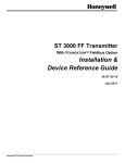
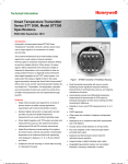
The STT35F Smart Temperature Transmitter is a microprocessor
based sealed unit that converts a primary sensor input into a digital
value proportional to the measured variable which is transmitted over
a two-wire pair.
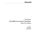
Figure 1-1
Typical STT35F Smart Temperature Transmitter
1
2
RTD
WP
FS
–
3
4
STT35F
Smart Temperature
Transmitter
+ T/C –
+
5
6
7
8
Continued on next page
2
STT35F Smart Temperature Transmitter
1.2
STT35F Smart Transmitter, continued
The STT35F transmits its output in a digital fieldbus protocol format
for direct digital communications with control systems.
The Process Variable (PV) is available for monitoring and control
purposes. The transmitter's body temperature is also available as a
secondary variable for monitoring purposes only through the
operator interface.
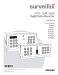
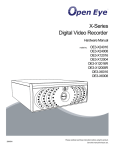
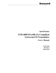
The block diagram in Figure 1-2 shows the transmitter circuits
involved in converting the input signal into a proportional output
signal. The boxed numbers in the diagram identify the phases which
are explained in the next paragraph.
Figure 1-2
STT35F Block Diagram with I/O Phase Identification
Resistance
thermometer or
strain gauge
Thermocouple
or mV inputs
1
2
Lo
Hi
3
4
+
RFI
Filter
RFI
Filter
RFI
Filter
1
2
CJC
3
4
RFI
Filter
1
Input Selection
-V
Current
Generator
Microprocessor
2
PSU
3
4
+
Ov V
Opto Isolators
5
Galvanic Isolation
Microprocessor
6
F
L
A
S
H
Comms
Power Reg.
MAU
E
P
R
O
M
+
V
Ov
PSU
E
E
P
R
O
M
Write
Protect
Y
E
S
N
O
Simulate
Enable
RFI
Filter
Y N
E O
S
5
RFI
Filter
6
–
7
7
8
+
Broadcasts digital signal
for 31.25 kbits/s fieldbus
Continued on next page
STT35F Smart Temperature Transmitter
3
1.2
What happens
in the different
phases
STT35F Smart Transmitter, continued
Table 1-1 gives an explanation for each phase of the I/O signal
processing identified in Figure 1-2.
Table 1-1
Explanation of I/O Phases
Phase
What Happens
1 & 2 Input signal is sampled at a rate of 4 times per second.
Signal is compensated for cold junction temperature or
resistance lead length as applicable.
Input signal is digitized.
3
Input signal is linearized, if applicable. Transmitter’s
4
Random Access Memory (RAM) contains characteristics
of most commonly used non-linear temperature sensors.
Input signal is transferred across galvanic isolation
5
interface.
Input signal is converted into proportional output signal in
6
digital form.
Digital output signal can be published over the fieldbus
7
network.
Continued on next page
4
STT35F Smart Temperature Transmitter
1.2
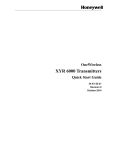
STT35F Smart Transmitter, continued
The STT35F Smart Temperature Transmitter is available with one of
these mounting approaches.
• Explosionproof housing, or
Mounting
approaches
• DIN rail mounting clips
The explosionproof housing is suitable for any one of these
mounting variations.
• Surface mounting on a wall,
• Direct sensor mounting to a thermowell, or
• 2-inch (50 mm) pipe mounting with our optional mounting bracket.
The DIN rail mounting clips are designed for a user-supplied top
hat or G type DIN rail.
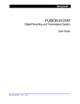
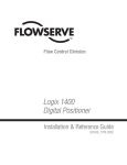
Figure 1-3 illustrates the mounting approaches for the STT35F
transmitter.
Figure 1-3
Mounting approaches for STT35F Transmitter
Explosionproof Housing (Optional)
Transmitter
Adjustments
DIN Rail
MountingClips
(Optional)
The STT35F has no physical adjustments. You can use a Personal
Computer (PC) running NI-FBUS Configurator software (or other
fieldbus device configuration application) to make any adjustments in
an STT35F transmitter.
STT35F Smart Temperature Transmitter
5
1.3
What is
Fieldbus
Fieldbus Overview
Fieldbus is an all digital, serial, two-way communication system which
interconnects industrial "field" equipment such as sensors, actuators,
and controllers. Fieldbus is a Local Area Network (LAN) for field
instruments with built-in capability to distribute the control application
across the network.
See Figure 1-4.
Figure 1-4
Fieldbus Connecting Control Room and Field Devices
Control Room
Device
(Operator
Interface)
Fieldbus LAN
STT 35 F
Open System
Design
STT 35 F
Fieldbus
Fieldbus
Device
Device
The Fieldbus Foundation has defined standards to which field
devices and operator/control stations communicate with one another.
The communications protocol is built as an "open system" to allow all
field devices and control equipment which are built to fieldbus
standards to be integrated into a control system, regardless of the
device manufacturer. This interoperability of devices using fieldbus
technology is to become the industry standard for automation and
distributed control systems.
Continued on next page
6
STT35F Smart Temperature Transmitter
1.3
Fieldbus Overview, continued
Hardware
Architecture
The physical architecture of fieldbus allows installation of fieldbus
devices using a twisted-pair cable. Often, existing wiring from
analog devices can be used to wire up digital fieldbus devices.
Multiple field devices can be connected on one cable (a multi-drop
link), rather than conventional point-to-point wiring used for analog
devices. For more details on wiring fieldbus networks, see Section
5.7.
Software
Architecture
Fieldbus software architecture provides for more control functions to
be available in the microprocessor-based field device. Since fieldbus
is a digital communication system, more data are available to
operators for process monitoring, trend analysis, report generation,
and trouble analysis. Device software changes can be downloaded
to field devices remotely from the operator station (or PC) in the
control room.
Application
An application is software that contains function block data and
operating parameters (objects) which help define the operation of a
device such as sensor data acquisition or control algorithm
processing. Some devices may contain more than one application.
Function Blocks Usually, a device has a set of functions it can perform. These
functions are represented as function blocks within the device. See
Figure 1-5. Function blocks are software that provide a general
structure for specifying different device functions. Each function
block is capable of performing a control function or algorithm.
Device functions may include analog input, analog output, and
Proportional Integral Derivative (PID) control. These blocks can be
connected together to build a process loop. The action of these
blocks can be changed by adjusting the block's configuration and
operating parameters.
Continued on next page
STT35F Smart Temperature Transmitter
7
1.3
Fieldbus Overview, continued
Figure 1-5 Fieldbus Devices Contain Device Applications and
Function
Blocks
Fieldbus Device
Device Application
Function Block
Function Block
Block Parameters
Block Parameters
Function Block
Function Block
Block Parameters
Block Parameters
Fieldbus LAN
FFfig5
STT35F
Transmitter
Application
8
The STT35F Fieldbus Transmitter contains the electronics interface
compatible for connecting to a fieldbus network. STT35F application
is configured using NI-FBUS Configurator software or other
configuration program. The configurator software allows the operator
to configure blocks, change operating parameters and create
linkages between blocks that make up the STT35F application. The
changes to the STT35F application are then written to the device and
initialized.
STT35F Smart Temperature Transmitter
1.4
Transmitter Order
Figure 1-6 shows the components that would be shipped and
received for a typical STT35F transmitter order.
Order
Components
Figure 1-6
Typical STT35F Transmitter Order Components
Ordered
• STT35F Smart Temperature Transmitter with optional explosionproof housing
Received
STT35F
Shipped
2
1
WP
FS
RTD
–
3
T/C
+
4
Operator
Manual
–
+
5
6
7
8
Explosionproof Housing (Optional)
Device Description Diskette
About
Documentation
STT35F Operator Manual EN1I-6196: One copy is shipped with each
transmitter for one to 9 units and 10 copies for 10 to 19 units etc.
This document provides information for checking, installing, wiring
and configuring the STT35F transmitter for operation. The Device
Description Diskette is provided with the manual.
STT35F Smart Temperature Transmitter
9
1.5
Option
Availability
Local Meter Option
The STT35F can be equipped with the Local Meter option as shown
in
Figure 1-7. The local meter provides read-only output value of the
Analog Input block in both % of full span and in actual engineering
units. The units are shown on the display as configured in the
transmitter. The engineering units are selected by accessing and
changing (if necessary) the OUT_SCALE parameter in the analog
input block. (See Section 7.4 for procedure).
Figure 1-7 Local Meter Faceplate
VAR
SEL.
UPPER
VALUE
0
%
100
UNITS
SET
LOWER
VALUE
Local Meter
Panel
Pushbuttons
The pushbuttons on the meter panel are not active and do not
function when pressed.
Continued on next page
10
STT35F Smart Temperature Transmitter
1.5
Local Meter Option, continued
Each Local Meter is a separate assembly which is designed to snap
fit on the transmitter’s electronics module. The option assembly
includes a cable and plug assembly for mating with a connector on
the transmitter’s terminal block. A meter end-cap which includes a
window is supplied on the bottom side of the transmitter’s housing so
you can view the meter display with the end cap installed.
About the
option
Figure 1-8
STT35F with Local Meter Option
VAR
SEL.
UPPER
VALUE
0
%
100
UNITS
SET
LOWER
VALUE
STT35F with Explosionproof
Housing (face view)
STT35F Smart Temperature Transmitter
Profile view
11
12
STT35F Smart Temperature Transmitter
2. INSTALLATION OVERVIEW
2.1
Section
Contents
Introduction
This section includes these topics:
Sectio
n
2.1
2.2
2.3
About this
Section
Topic
See
Page
Introduction...................................................... 13
Installation Components .................................. 14
Installation/Operation Tasks ............................ 16
This section provides a list of components needed to install and
operate the STT35F transmitter. Also provided is a list of typical
start-up tasks and places where you can find detailed information
about performing the tasks.
STT35F Smart Temperature Transmitter
13
2.2
Components
Needed for
Installation
Installation Components
The STT35F transmitter contains electronics that enables it to
operate using the FOUNDATION Fieldbus protocol. This digital
interface requires a number of components to provide control and
data communications between field devices and the control room
environment. Table 2-1 outlines the basic component parts needed to
install and operate the STT35F on a fieldbus network.
Table 2-1
Components Required for STT35F Installation
Components
STT35F Transmitter
(Field Device)
Power Supply
Power Conditioner
Fieldbus Cable
Fieldbus Terminators
Fieldbus IS Barriers
(For hazardous area
installations)
Fieldbus Wiring Blocks
Description
Measures process temperature and
transmits process data to operator
station or host computer.
Furnishes DC power to fieldbus
devices.
Acts as a filter to prevent the power
supply from interfering with the fieldbus
signaling. (May be part of a Fieldbus
power supply).
Twisted pair shielded wire used to
interconnect fieldbus devices.
A signal termination device used to
prevent reflected signals (noise) from
distorting Fieldbus communications.
Intrinsic safety wire barriers are
required for hazardous location
installations.
Wiring blocks allowing easy connection
of devices, cable, terminators, surge
suppressors and other fieldbus network
components.
Continued on next page
14
STT35F Smart Temperature Transmitter
2.2
Installation Components, continued
In the control room an operator station, personal computer or host
computer acts as the operator interface to the fieldbus network.
Using supervisory control software applications, the field devices on
a fieldbus network can be monitored and controlled at the operator
interface.
Figure 2-1 shows how these components go together to operate on a
fieldbus network.
Operator
Interface
Figure 2-1 Fieldbus Network Components
Operator Station or
Host Computer
Power
Supply
PC
T
Fieldbus Cable
T
Fieldbus Devices
T
= Terminator
PC = Power Conditioner
STT35F Smart Temperature Transmitter
15
2.3
Installation
Tasks
Installation/Operation Tasks
Installation of the STT35F is not difficult. The tasks for installing and
operating the transmitter are outlined in Table 2-2
Installation/Operation Task Summary.
Table 2-2
Task
1
2
3
4
5
Procedure
Bench Check (optional)
(Off-line configuration)
Pre-installation
Considerations
Install STT35F Transmitter
• Mounting
• Piping
• Wiring
Power Up Transmitter
Establish Communications
Initial checks
Configure STT35F
transmitter
6
Operation
-
Troubleshooting (if
problems arise)
Replacement (if needed)
-
16
Installation/Operation Task Summary
Refer to
Section 3
Section 4
Section 5
Section 5.2 - 5.3 - 5.5 - 5.6
Section 5.4
Section 5.7
Section 5.10
Section 6.7
Section 6.8
Section 6.9 & 8 in this manual
and also the user manual
supplied with NI-FBUS
Configurator.
Section 7. Also see
supervisory control application
documentation.
Section 9
Section 10
STT35F Smart Temperature Transmitter
3. OFF-LINE CONFIGURATION (optional)
3.1
Section
Contents
Introduction
This section includes these topics:
Sectio
n
3.1
3.2
3.3
Topic
Introduction...................................................
Off-line Bench check ....................................
Mode of Measurement Considerations.........
See
Page
17
18
20
About this
Section
The off-line configuration is an optional procedure for checking your
transmitter. This section provides a procedure for configuring the
STT35F off-line, meaning you can load configuration information into
the transmitter before it is connected in a fieldbus network. This
enables you to perform a bench check and configuration of the
transmitter before installation. Calibration is also possible before the
transmitter is installed in the field.
Device
Calibration
Your transmitter was factory calibrated. This means there is no need
to calibrate the transmitter during installation.
STT35F Smart Temperature Transmitter
17
3.2
Configure
STT35F before
Installation
Off-line Bench check
Using the NI-FBUS Configurator (or other fieldbus device
configuration application), you can perform an off-line check of the
STT35F before it is mounted and connected to the process
hardware and the fieldbus network. By wiring the transmitter to the
fieldbus interface of a PC and using a fieldbus power supply to
furnish power to the transmitter, you can read and write parameters
in the STT35F.
See Figure 3-1 and Table 3-1 for procedure.
Figure 3-1
Bench check Setup Figure
PC or
Operator Station
PC
*
J
= Junction Block
T
= Terminator
PC
Power
supply
= Power Conditioner
(May be contained in
power supply)
TT
T
J
1 2 3 4
WP
FS
Table 3-1
Step
1
RTD T/C –
+
– +
5 6 7
8
Bench check Wiring Procedure
Action
Connect fieldbus cable to junction block and to fieldbus
interface card on the PC.
ATTENTION Observe polarity of fieldbus cable throughout
the network.
Continued on next page
18
STT35F Smart Temperature Transmitter
3.2
8
Action
Observing polarity, connect positive fieldbus lead to Signal + terminal and
negative fieldbus lead to Signal – terminal.
Example: Connecting fieldbus to transmitter.
7
+
3
T/C
3
4
5
6
7
8
+
5
ate
–
FS
WP
N
1
-
2
Fieldbus Cable
RTD
+
–
4
Step
2
Bench check Wiring procedure, continued
6
Table 3-1
Off-line Bench Check, continued
For bench check purposes only, put a jumper across the input terminals 3
and 4. However, if you know that your transmitter is configured for an RTD
input, put a 100 to 300 ohm resistor across terminals 2, 3, and 4 instead.
This is only done to avoid Critical alarms for Open Input during bench
check.
At the junction block, connect a fieldbus terminator in parallel with the
transmitter. Refer to Figure 3-1.
Connect a power supply, power conditioner (if needed), and a fieldbus
terminator to the fieldbus cable.
Turn on PC.
Turn on power supply.
Start fieldbus configuration application on PC.
Once you have established communications between the
Establish
Communications transmitter and the PC, you can then check out the transmitter.
Assign Bus
Address and
Device Tag
You can check the device ID and serial number of the transmitter,
assign a network node address to the device and assign tag names
to the device.
Note that the transmitter is shipped with default node addresses and
tag names that appear at start-up. These can be changed to actual
network addresses and tag names.
Device
Configuration
You can view the various block parameters that make up the
transmitter configuration, enter parameter values for your process
application and write them to the device.
STT35F Smart Temperature Transmitter
19
3.3
About
measurement
mode
Table 3-2
Mode of Measurement Considerations
The STT35F transmitter determines the mode of measurement based
on the sensor configuration and the sensor type. This means you must
be sure that sensor type and the sensor configuration are correct at
startup or whenever the sensor type and/or configuration is changed
in the transducer block and the transducer block is changed back to
auto mode. Table 3-2 summarizes the possible modes of
measurement.
Summary of Mode of Measurement Determinations
If sensor type
is
Millivolt (mV) or Thermocouple
Type (B, C, . . . )
And sensor
configuration is for
Single sensor
Then Mode of Measurement
is
Straight temperature or
millivolts
Thermocouple Type (B, C, . . . ) Redundant
Straight temperature with
backup thermocouple
Thermocouple Type (B, C, . . . ) Differential
Differential temperature (T/C1 T/C2)
0 to 2000 Ohms, Cu 10 probe,
or Cu 25 probe
2- or 3-wire ohms
source or single RTD
2- or 3-wire sensor
or single sensor
4-wire sensor single
sensor
2- or 3-wire single
RTD
2- or 3-wire single
sensor
4-wire sensor
Straight temperature or ohms
Differential
Differential temperature (RTD1
- RTD2)
0 to 2000 Ohms, Cu 10 probe,
or Cu 25 probe
Resistance Temperature
Detector (Pt100, Pt200 . . . )
Resistance Temperature
Detector (Pt100, Pt200 . . . )
Resistance Temperature
Detector (Pt100, Pt200 . . . )
ATTENTION
20
Straight temperature or ohms
Straight temperature
Straight temperature
See Section 5.7 in this manual for wiring details.
STT35F Smart Temperature Transmitter
4.
4.1
Section
Contents
PRE-INSTALLATION CONSIDERATIONS
Introduction
This section includes these topics:
Section Topic
4.1
4.2
4.3
About this
Section
See
Page
Introduction ........................................................... 21
Considerations for STT35F Transmitter ................ 22
Considerations for Local Meter Option .................. 24
This section reviews things you should take into consideration
before you install the transmitter. Of course, if you are replacing an
existing STT35F transmitter you can skip this section.
STT35F Smart Temperature Transmitter
21
4.2
Evaluate
conditions
Considerations for STT35F Transmitter
The STT35F transmitter is designed to operate in common indoor
industrial environments as well as outdoors. To assure optimum
performance, evaluate these conditions at the mounting area relative
to published transmitter specifications and accepted installation
practices for electronic transmitters.
• Environmental Conditions
– Ambient Temperature
– Relative Humidity
• Potential Noise Sources
– Radio Frequency Interference (RFI)
– Electromagnetic Interference (EMI)
• Vibration Sources
– Pumps
– Motorized Valves
• Process Characteristics
– Temperature (radiated heat)
Figure 4-1 illustrates typical mounting area considerations to make
before installing a transmitter.
Figure 4-1
Typical Mounting Area Considerations Prior to
Installation
Lightning
(EMI)
Relative
Humidity
Ambient
Temperature
Large Fan Motors
(EMI)
Transceivers
(RFI)
Process
TemperatureRadiated
Pump
(vibration)
Continued on next page
22
STT35F Smart Temperature Transmitter
4.2
Considerations for STT35F Transmitter, Continued
Temperature/hum
idity ratings
ATTENTION
Table 4-1 lists the temperature and humidity ratings for reference,
rated, operating, and transportation and storage conditions for an
STT35F transmitter.
See Specification and Model Selection Guide for complete
performance specifications for the Version STT35F transmitter.
Table 4-1
Temperature and Humidity Ratings
Parameter
Reference
Rated
Condition
Condition
Ambient Temperature
°C
23 ±1
–40 to 85
°F
73 ±2
–40 to 185
Relative Humidity
10 to 55
5 to 95 (Non% RH
condensing)
Operating
Limits
Transportation
and Storage*
–40 to 85
–40 to 185
5 to 100 (Noncondensing)
–50 to 100
–58 to 212
5 to 100
*While transmitters can be stored at these conditions for a reasonable length of time, it is best to store transmitters in an
area that has more or less normal ambient conditions.
Power
Requirements
The STT35F is a bus-powered device, meaning that it receives its
power from the dc voltage on a fieldbus wiring segment. There are
certain guidelines and limitations regarding the wiring of fieldbus
devices. See Section 5.7 for more information on wiring the
transmitter.
Table 4-2 lists the operating power requirements for the STT35F
transmitter.
Table 4-2
STT35F Power Requirements
Minimum
Maximum
9 Vdc † @ 27mA
32 Vdc @ 27mA ‡
Static Power
† The physical layer parameters of the transmitted waveform are out of specification
below 9.5 volts.
‡ Current ramp at startup is 1.2 mA/ms.
Basic operation
Inputs are sampled at a rate of 4 times per second, digitized by the
A/D converter, compensated for cold junction or resistance lead
length and transferred across the galvanic isolation interface.
However, the AI block can be run faster than 4 times a second. In
this case, the PV published over the network will not be refreshed
every time.
STT35F Smart Temperature Transmitter
23
4.3
Considerations for Local Meter Option
Reference
Specifications
Table 4-3
Table 4-3 lists pertinent Meter specifications for reference.
Local Meter Specifications
Operating Conditions
Parameter
Ambient Temperature
Relative Humidity
%RH
Rated
Extreme, Transportation
and Storage
–40 to 185 °F
–40 to 85 °C
–58 to 194 °F
–50 to 90 °C
10 to 90
0 to 100
Design
Accuracy
No error. Reproduces transmitter signal exactly within its
resolution.
Display Resolution
±0.005 for ±19.99 reading
range,
±0.05 for ±199.9 reading range,
±0.5 for ±1999 reading range,
±5 for ±19990 reading range,
±50 for ±199900 reading range,
±500 for ±1999000 reading
range,
±50000 for ±19990000 reading
range.
Display Update Rate
Above 32 °F (0 °C): ½ second
@ or below 32 °F (0 °C): 1½ seconds.
ATTENTION
24
Shown as:
19.99
199.9
1999
19.99 K
199.9 K
1999 K
19990 K
The rated temperature limits for the local meter are listed above and are
true in that no damage to the meter will occur over these temperatures
however the readability of the LCD is affected if taken to these extreme
temperatures:
• The LCD will turn black at some temperature between 80 and 90°C
(176 and 194°F), rendering the display unreadable. This effect is only
temporary and normally occurs at 90°C (194°F).
• At low temperatures, the update rate of the display is lengthened to 1.5
seconds due to the slower response time of the display. At –20°C (4°F), the display becomes unreadable due to slow response of the
LCD. This is also only temporary and normal readability will return
when temperature returns above –20°C (-4°F).
STT35F Smart Temperature Transmitter
5. TRANSMITTER INSTALLATION
5.1
Section
Contents
Introduction
This section includes these topics:
Sectio
n
5.1
5.2
5.3
5.4
5.5
5.6
5.7
5.8
5.9
5.10
About this
Section
Topic
See
Page
Introduction........................................................ 25
Mounting Variations........................................... 26
Surface Mounting Explosionproof Housing........ .. 27
Pipe Mounting Explosionproof Housing............. 29
Thermowell Mounting Explosionproof Housing . 31
32
DIN Rail
33
Mounting..................................................
Wiring STT35F Transmitter ............................... 47
External Lightning Protection............................. 48
Internal Surge Protection................................... 50
Power Up Transmitter........................................
This section provides information about the mechanical and
electrical installation of the STT35F transmitter. It includes
procedures for mounting, piping and wiring the transmitter for
operation.
STT35F Smart Temperature Transmitter
25
5.2
Overview
Mounting Variations
You can mount a transmitter installed in an optional explosionproof
housing to a:
• Surface of a wall,
• Thermowell of a sensor, or
• 2-inch (50 mm) vertical or horizontal pipe, using our optional
mounting bracket.
You can also mount a transmitter to a top hat or G type DIN rail using
our optional DIN rail clips.
Figure 5-1 shows typical explosionproof housing and DIN rail-mounted
transmitter installations for comparison.
Figure 5-1
Typical Explosionproof Housing and DIN Rail-Mounted Installations
Thermowell Mounting
Vertical Pipe Mounting
Surface Mounting
7
6
+
5
RTD
FS
WP
–
1
2
+
3
T/C
–
4
8
DIN Rail Mounting
Continued on next page
26
STT35F Smart Temperature Transmitter
5.3
Surface Mounting Explosionproof Housing
Table 5-1 summarizes typical steps for mounting a transmitter in an
explosionproof housing on the surface of a wall or panel.
User must supply hardware, such as two bolts with nuts and
lockwashers, to attach explosionproof housing to surface.
Procedure
ATTENTION
Table 5-1
Step
1
Mounting STT35F Transmitter to a Surface
Action
Position explosionproof housing in desired location on mounting
surface.
ATTENTION
You can rotate the housing in 90 degree
increments to meet your particular installation requirements. Note
that the transmitter itself can be rotated 180 degrees within the
housing. Example of rotated mounting positions for the housing:
2
3
4
Use center punch or scribe to mark location of holes in housing
on surface.
Prepare surface for user-supplied mounting hardware as
required.
Secure housing to surface using mounting holes and usersupplied hardware.
Example - Securing housing to wall or panel.
Explosionproof Housing
Wall or Panel
User-Supplied Hardware
21049
Continued on next page
STT35F Smart Temperature Transmitter
27
5.3
Surface Mounting Explosionproof Housing, Continued
Procedure,
continued
Table 5-1
continued
Mounting STT35F Transmitter to a Surface,
Step
Action
If applicable, connect conduit to 1/2-inch NPT female wiring
5
outlet connection in housing observing local connection
practices.
Go to Wiring section.
6
Dimensions
Figure 5-2
Figure 5-2 shows explosionproof housing, surface mounting
dimensions for reference.
Surface Mounting Dimensions
142
5.59
Housing without
meter
121.8
4.79
94
3.70
61
2.40
Clearance for
cap removal
95
3.78
Housing with
meter
149
5.90
28
STT35F Smart Temperature Transmitter
22718
5.4
Procedure
Pipe Mounting Explosionproof Housing
Table 5-2 summarizes typical steps for mounting a transmitter in an
explosionproof housing to an optional pipe mounting bracket.
Table 5-2
Step
1
Mounting STT35F Transmitter to a Bracket
Action
Position explosionproof housing in desired location on flat
side of our optional mounting bracket. Align mounting
holes in housing with holes in bracket.
ATTENTION You can rotate the housing in 90 degree
2
3
increments on the mounting bracket to meet your
installation requirements. Note that you can rotate the
transmitter itself 180 degrees within the housing.
Use two M8 x 25 mm long bolts with nuts and
lockwashers supplied with mounting bracket to secure
housing to bracket.
Position bracket on vertical or horizontal pipe and secure
with supplied U-bolts.
Example - Securing housing to 2-inch (50 mm) vertical
pipe.
Explosionproof Housing
2-inch (50mm)
vertical pipe
M8 x 25mm long bolt with
lockwasher and nut (2)
Mounting bracket
with U-bolts
21050
Continued on next page
STT35F Smart Temperature Transmitter
29
5.4
Pipe Mounting Explosionproof Housing, Continued
Procedure,
continued
Table 5-2
Step
4
5
Action
If applicable, connect conduit to 1/2-inch NPT female wiring
outlet connection in housing observing local connection
practices.
Go to Wiring section.
Figure 5-3 shows explosionproof housing, pipe mounting dimensions
for reference.
Dimensions
Figure 5-3
Mounting STT35F Transmitter to a Bracket, continued
Pipe Mounting Dimensions
Vertical Pipe Mounting
142
5.59
14.9
0.59
61.8
2.43
40
1.57
191.5
7.53
60
2.36
38.7
1.52
14.9
0.59
94
3.70
115
4.53
61
2.40
95
3.78
Clearance for
cap removal
Housing with
meter
61
2.40
Clearance for
cap removal
30
149
5.90
STT35F Smart Temperature Transmitter
5.5
Thermowell Mounting Explosionproof Housing
Considerations
Review these considerations before mounting an STT35F
transmitter in an explosionproof housing directly to a
thermowell.
• Be sure to use an extension pipe that is long enough to keep any
heat transfer from the process from raising the ambient
temperature above the 85°C (185°F) operating limit.
• If an RTD or a T/C sensor is being used, be sure to use a springload accessory to hold the sensor against the end of the
thermowell.
• Be sure sensor leads extend at least 5.9 inches (150 mm) from
the end of the thermowell or the extension pipe as applicable.
Procedure
Table 5-3 summarizes typical steps for mounting a transmitter in an
explosionproof housing directly to a thermowell.
Table 5-3
Step
1
2
Mounting STT35F Transmitter to a Thermowell
Action
Follow accepted piping practices to connect extension pipe
and fittings to thermowell and provide 1/2-inch NPT male
connection to 1/2-inch NPT female outlet connection in
explosionproof housing.
Feed sensor leadwires into conduit connection on one side of
explosionproof housing and secure housing to pipe fitting
from thermowell.
ATTENTION Be sure that there is enough slack in sensor
4
5
Figure 5-4
leadwires for connection to transmitter’s terminals.
Example - See Figure 5-4.
If applicable, connect conduit to 1/2-inch NPT female wiring
outlet connection in housing observing local connection
practices.
Go to Wiring section.
Securing Housing to Thermowell
Hot Process
Extension Pipe
Explosionproof Housing
Thermowell
Fittings
Vessel
Insulation
21051
STT35F Smart Temperature Transmitter
31
5.6
DIN Rail Mounting
Table 5-4 summarizes typical steps for mounting a transmitter to a
top hat or G type DIN rail.
Procedure
Table 5-4
Step
1
Mounting STT35F Transmitter to a DIN Rail
Action
With front of transmitter facing you, turn transmitter on its left
side. Attach mounting clips to rear of transmitter with screws
supplied through mounting bosses on top and bottom of
transmitter.
Example - Installing DIN rail clips on back of transmitter.
DIN Rail clips
2
Dimensions
Figure 5-5
Mounting boss
Screw
Snap transmitter onto DIN rail.
Figure 5-5 shows DIN rail clip dimensions for reference.
DIN Rail Mounting Dimensions
Top Hat DIN Rail
G DIN Rail
40 mm
1.57 in
46 mm
1.81 in
46 mm
1.81 in
40 mm
1.57 in
85.5 mm
3.37 in
32
90 mm
3.54 in
STT35F Smart Temperature Transmitter
5.7
Wiring the
Transmitter to a
Fieldbus
Network
Wiring STT35F Transmitter
The STT35F transmitter is designed to operate in a two-wire fieldbus
network. Although wiring the transmitter to a fieldbus network is a
simple procedure, there are a number of rules that should be
followed when constructing and wiring a network. This section
provides general guidelines that should be considered when wiring
the transmitter to a fieldbus network segment. A procedure is given
in this section for properly wiring the transmitter.
Refer to Fieldbus Foundation document AG-140, Wiring and
For Detailed
Fieldbus Wiring Installation 31.25 kbit/s, Voltage Mode, Wire Medium Application
Guide for complete information on wiring fieldbus devices and
Information
building fieldbus networks.
Fieldbus
Device Profile
Type
The STT35F is identified as either of the following Fieldbus Device
Profile Types in Table 5-5, (as per Fieldbus document #FF-816):
Table 5-5
Foundation Fieldbus Profile Types
Device Profile
Type:
Characteristic
111
113
X
X
Uses standard-power signaling to communicate on
a fieldbus network.
X
X
Is a bus-powered device.
(The transmitter does not have an internal power
supply and so it receives its dc power from the
fieldbus).
X
Is acceptable for intrinsically safe (I.S.)
applications.
X
Is acceptable for non I.S. applications.
Fieldbus
Network
Components
There are a number of basic components used in constructing a
fieldbus network. These items can include:
• Fieldbus cable - Consists of a shielded, twisted pair made to
fieldbus specifications. (Although existing two-wire cable can be
used in some installations, fieldbus cable is recommended for
new installations.)
• Fieldbus power supply.
• Power conditioner is a fieldbus component that provides
impedance matching between the power supply and the fieldbus
segment. (This may be included as part of a fieldbus power
supply.)
Continued on next page
STT35F Smart Temperature Transmitter
33
5.7
Fieldbus
Network
Components,
Continued
Wiring STT35F Transmitter, Continued
•
Fieldbus terminators - This component acts as a signal
termination. Two are required for each fieldbus segment. One
is connected at or near each end of a network segment.
Junction block - This is a terminal block used as a junction point
for fieldbus cable leads to individual devices.
Fieldbus I.S. barriers - Limits the available power to the fieldbus
segment to eliminate explosion hazards. (Barriers must be
designed for fieldbus networks.)
•
•
Fieldbus
Network Wiring
Schemes
There are various schemes that can be used to wire devices in a
fieldbus network. Devices can be connected:
• In a daisy-chain, (in parallel)
• To a bus, where the devices are attached in a multidrop scheme
• In a tree fashion, where devices are connected to a network
segment via a common junction block.
Daisy-Chain
Wiring
The fieldbus cable is routed from device to device in parallel along a
bus segment. The cable is interconnected at the terminals of each
field device. (This installation must be powered down to modify or
replace transmitter.) This scheme is illustrated in Figure 5-6.
Figure 5-6
Daisy-Chain Wiring Scheme
To Control System
T
PC
Fieldbus Interface
Power
Supply
= Terminator
= Power Conditioner
= Fieldbus Devices
PC
T
T
24102
Continued on next page
34
STT35F Smart Temperature Transmitter
5.7
Bus with Spurs
Wiring
Wiring STT35F Transmitter, Continued
In this scheme, field devices are connected to a bus by a length of
fieldbus cable called a spur (or drop). The spur can vary in length
from 1 meter (3.28 ft.) to 120 m (394 ft.). Figure 5-7 shows devices
and spurs connected to a bus segment.
Figure 5-7
Bus with Spurs Wiring
To Control System
= Terminator
T
PC = Power Conditioner
Fieldbus Interface
Power
Supply
= Fieldbus Devices
PC
T
T
Tree Wiring
Scheme
In this scheme, field devices are connected to a single fieldbus
segment via a spur cable to a common junction block, terminal, or
marshalling panel. This scheme is practical if devices on the segment
are well separated, but in the general area of the same junction block.
Figure 5-8 shows the tree wiring scheme.
Figure 5-8
Fieldbus Network using Tree Wiring Scheme
To Control System
JB/T
PC
Fieldbus Interface
Power
Supply
= Junction block terminator
= Power Conditioner
= Fieldbus Devices
PC
T
JB/T
Continued on next page
STT35F Smart Temperature Transmitter
35
5.7
Wiring STT35F Transmitter, Continued
Fieldbus Network
Limitations
A number of factors limit the size of a fieldbus network:
1. The cable type used in the wiring system limits the length of a
network segment. (See Fieldbus Cable Types.)
2. The number of field devices connected on a segment is limited
depending on:
- voltage of the power supply,
- resistance of the cable and
- current drawn by each device.
(See Voltage, Resistance and Current.)
3. Attenuation and distortion of the signal on the fieldbus due to:
- resistance of the cable,
- varying characteristic impedance along the cable,
- signal reflections from spur connections, and
- other factors that limit the size of a network segment.
Fieldbus Cable
Types
Various types of cable are useable for fieldbus network wiring.
Table 5-6 lists the cable types. Please note that Type A is the preferred
cable to use for fieldbus; then type B, etc.
Table 5-6 Fieldbus Cable Types
Fieldbus Cable
Type
Type A ⇒
Construction
Shielded, twisted pair
⇓
Type B ⇒
Multi-twisted pair, with shield
⇓
Type C ⇒
Multi-twisted pair, without
shield ⇓
Type D ⇒
Multi-core, without
twisted pairs and
having an overall
shield
⇓
Parameter
Characteristic Impedance Ohms
Maximum DC resistance Ohms/km
Maximum attenuation - db/km
Wire Size - AWG #
Wire cross sectional area - mm2
Maximum Capacitive unbalance
- pf
* Not specified
Conditions
31.25 kHz
D
*
C
*
per conductor
20
39 kHz
8
16
1,25
*
1 kilometer
length
132
B
70130
56
A
80120
24
8
26
0,13
*
5
22
0.32
2000
3
18
0.8
2000
Continued on next page
36
STT35F Smart Temperature Transmitter
5.7
Wiring STT35F Transmitter, Continued
Voltage,
Resistance and
Current
Power supply output voltage, cable resistance and device current
requirements limit the number of devices on a network segment.
1. The output voltage of the power supply must be considered when
building a fieldbus segment. Typical fieldbus devices require a
minimum of 9 volts to operate. (See power requirements for the
STT35F in
Section 4.2).
2. Resistance of the fieldbus cable produces a voltage drop along a
segment and must also be considered.
3. The device startup current as well as the operating current must
be considered, because some devices require considerably more
current when they are first powered up and begin to operate.
(The STT35F does not require extra current at start up.)
The power calculation for a network segment should allow for these
factors (voltage, current and resistance), otherwise the network may
not start up when power is first applied.
Number of
Devices and
Spur Length
For the bus with spurs and tree wiring scheme, there are guidelines
for the length of spurs and the number of devices that can be
connected on these spurs. The guidelines established are only
recommendations for the maximum cable length to assure adequate
signal quality. Spur length depends on:
• Cable type/characteristics/wire gauge, (Types A, B, C, or D)
• Wiring scheme, (bus or trees)
• Number and type of devices, (are devices bus or self-powered
and are they suitable for I.S. applications).
In any fieldbus segment there may be a variety of cable and the
quality of existing cable may vary, therefore you should try to use the
shortest cable length possible.
For details on these guidelines, refer to the Fieldbus wiring
document number AG-140.
ATTENTION
STT35F Wire
Connections
If you are installing intrinsically safe field devices in hazardous
areas, there are more things to consider. See Intrinsically Safe
Applications section.
Fieldbus signal communications and DC power are supplied to the
transmitter using the same fieldbus twisted-pair cable.
Continued on next page
STT35F Smart Temperature Transmitter
37
5.7
Intrinsically
Safe
Applications
Wiring STT35F Transmitter, Continued
Fieldbus barriers should be installed per manufacturer’s instructions
for transmitters to be used in Intrinsically Safe (I.S.) applications.
The number of field devices on a segment may be limited due to
power limitations in hazardous area installations. Special fieldbus
barriers and special terminators may be required. Also the amount
of cable may be limited due to its capacitance or inductance per unit
length.
For Detailed I.S. Refer to Fieldbus Foundation document AG-163, 31.25 kbit/s
Intrinsically Safe Systems Application Guide for more detailed
Information
information on connecting fieldbus devices for I.S. applications.
Input wiring
procedure
ATTENTION
The procedure in Table 5-7 shows the steps to connect the input
signal to the transmitter.
All wiring must comply with local codes, regulations, and ordinances.
Table 5-7
Step
1
2
3
4
Wiring Input to the Transmitter
Action
Then…
go to Step 2
If transmitter …
is installed in an
explosionproof housing
is not installed in an
go to Step 5
explosionproof housing
Remove cap from explosionproof housing.
If transmitter is supplied with an optional integral meter, pull
meter from transmitter mounting adapter and unscrew plastic
cage to expose wiring connections on transmitter.
Feed input leads through one of conduit entrances on either
side of explosionproof housing. Plug whichever entrance you
do not use.
Continued on next page
38
STT35F Smart Temperature Transmitter
5.7
Input wiring
procedure,
continued
Wiring STT35F Transmitter, Continued
Table 5-7
Wiring Input to the Transmitter, continued
Ste
Action
p
5 Strip 1/4 inch (6.35 mm) of insulation from input leads.
If input is from …
Then…
Thermocouple or millivolt
Observing polarity, connect
source
positive input lead to T/C +
terminal 3 and negative input
lead to T/C – terminal 4.
See Figure 5-9.
2-wire RTD or ohms
Connect RTD leads to
source
terminals 2 and 3. Insert
jumper between terminals 3
and 4.
See Figure 5-11A.
3-wire RTD or ohms
Connect RTD leads to
source
terminals 2, 3, and 4. See
Figure 5-11A.
4-wire RTD or ohms
Connect RTD leads to
source
terminals 1, 2, 3, and 4
See Figure 5-11A.
Two 2-wire RTDs for
Connect RTD 1 leads to
differential measurement
terminals 3 and 4 and RTD 2
leads to terminals 2 and 4.
See Figure 5-11B.
Two thermocouples for
Connect thermocouple 1 leads
redundant operation
to terminals 3 (+) and 4 (–) and
thermocouple 2 leads to
terminals 2 (+) and 4 (–). See
Figure 5-10.
Two thermocouples for
Connect thermocouple 1 leads
differential measurement
to terminals 3 (+) and 4 (–) and
thermocouple 2 leads to
terminals 2 (+) and 4 (–). See
Figure 5-10.
6 Replace integral meter, plastic cage and cap, if applicable.
Continued on next page
STT35F Smart Temperature Transmitter
39
5.7
Wiring STT35F Transmitter, Continued
Input wiring
procedure,
continued
Figure 5-9
Single Thermocouple or Millivolt Source Input Wiring Connections
Thermocouple
Millivolt
Source
Thermocouple
Thermocouple
Extension
Wire
Thermocouple
Extension
Wire
1
FS
+
RTD
–
Copper
Wire
–
3
4
1
FS
6
7
8
Thermocouple Connections
with Internal Cold
Junction Compensation
About
thermocouple
extension wire
2
RTD
–
–
3
4
1
FS
6
7
2
8
3
RTD
WP
+ T/C –
+
5
–
4
+ T/C –
+
5
6
7
8
Millivolt Connections
Thermocouple Connections
with External Cold
Junction Compensation
Table 5-8 lists the thermocouple extension cable color codes
commonly used in the United States for extending thermocouple
leads for a given thermocouple type. One of these cables is likely to
be used for connecting a thermocouple to the STT35F transmitter.
Table 5-8
Cable for
Thermocouple Type
B
E
J
K
R&S
T
40
–
+
WP
+ T/C –
+
5
+
–
Thermocouple
Reference
2
WP
+
Thermocouple Extension Cable Color Codes
Leads or Cores
Positive +
Gray
Violet
White
Yellow
Black
Blue
Cable Cover
Negative –
Red
Gray
Red
Violet
Red
Black
Red
Yellow
Red
Green
Red
Blue
Continued on next page
STT35F Smart Temperature Transmitter
5.7
Wiring STT35F Transmitter, Continued
Input wiring
procedure,
continued
Figure 5-10
Two Thermocouples for Redundant Operation or
Differential Measurement Input Wiring Connections.
Thermocouple 2
–
+
Thermocouple 1
+
1
2
RTD
WP
FS
–
–
3
4
+ T/C –
+
5
6
7
8
Thermocouple Connections
for Redundant Operation
or Differential
Measurement
ATTENTION
You must select the appropriate sensor through the sensor type and
sensor configuration transducer block parameters for the transmitter to
select the correct measurement mode based on the input wiring.
Continued on next page
STT35F Smart Temperature Transmitter
41
5.7
Wiring STT35F Transmitter, Continued
Input wiring
procedure,
continued
Figure 5-11A
Single RTD or Ohms Source Input Wiring Connections
RTD or ohms
source
Legend
W = White
R = Red
W
R
1
2
RTD
WP
keep Length/Resistance
of All Leads Equal
keep Length/Resistance
of All Leads Equal
3
4
W
R
1
2
RTD
WP
+ T/C –
3
+
4
–
–
+
5
6
7
2-Wire RTD Connections
8
FS
6
7
3-Wire RTD Connections
2
WP
+
5
1
RTD
T/C –
FS
FS
R
W
W
R
–
8
R
3
4
+ T/C –
+
5
6
7
8
4-Wire RTD Connections
Continued on next page
42
STT35F Smart Temperature Transmitter
5.7
Wiring STT35F Transmitter, Continued
Input wiring
procedure,
continued
Figure 5-11B
Two 2-wire RTDs for Differential Measurement Input Wiring
Connections.
Legend
W = White
R = Red
RTD 2
R
RTD 1
W
1
W
R
2
3
RTD
WP
Keep Length/Resistance
of All Leads Equal
4
+ T/C –
FS
–
+
5
6
7
8
Two RTDs for Differential Measurement
Connections
ATTENTION
Output/power
wiring
procedure
ATTENTION
You must select the appropriate sensor through the sensor type and
sensor configuration transducer block parameters for the transmitter to
select the correct measurement mode based on the input wiring.
The procedure in Table 5-9 shows the steps for connecting
output/power to the transmitter.
All wiring must comply with local codes, regulations, and ordinances.
Table 5-9
Wiring Output/Power to the Transmitter
Step
Action
1
If transmitter …
Then…
is installed in an
go to Step 2
explosionproof housing
is not installed in an explosionpr go to Step 5
housing
Continued on next page
STT35F Smart Temperature Transmitter
43
5.7
Wiring STT35F Transmitter, Continued
Output/power
wiring procedure,
continued
Table 5-9
Wiring Output/Power to the Transmitter, continued
Step
Action
Remove
cap
from
explosionproof
housing.
2
If transmitter is supplied with an optional integral meter, pull
3
meter from transmitter and unscrew plastic cage to expose
wiring connections on transmitter.
Feed output/power wires through one of conduit entrances
4
on either side of explosionproof housing. Plug whichever
entrance you do not use.
Strip 1/4 inch (6.35 mm) of insulation from output/power
5
wires.
If transmitter is
Then…
supplied…
without an integral meter
Observing polarity, connect
positive loop output/power wire
to + terminal 6 and negative
loop output/power wire to –
terminal 5. See Figure 5-12.
with an integral smart
Connect the local meter
meter
connector into the 6 pin
connector.
Observing polarity, connect
positive loop output/power wire
to + terminal 6 and negative
loop output/power wire to –
terminal 5. See Figure 5-12.
Replace
integral
meter,
plastic
cage and cap, if applicable.
6
Continued on next page
44
STT35F Smart Temperature Transmitter
5.7
Wiring STT35F Transmitter, Continued
Output/power
wiring procedure,
continued
Figure 5-12
Typical Output/Power Wiring Connections Without
Meter or With Local Meter
Sensor
-
+
1
2
3
RTD
WP
FS
–
4
+ T/C –
+
5
-
6
7
8
Fieldbus
cable
+
Sensor
Optional
Smart Meter
-
+
Honeywell
1
2
RTD
WP
3
4
0
%
100
+ T/C –
FS
–
+
5
-
Ground
connection
6
7
8
+
Fieldbus
cable
Each explosionproof housing includes a ground terminal for
connecting the housing to a suitable earth ground using a #6 or larger
nickel-clad wire.
When your housing is supplied with an optional transient protector,
you must connect the green wire from the protector to the ground
terminal as shown in Figure 5-13 to make the protection effective.
Continued on next page
STT35F Smart Temperature Transmitter
45
5.7
Wiring STT35F Transmitter, Continued
Ground
connection,
continued
Figure 5-13 Ground Connection with Transient Protector
Ground
Terminal
Green
(Ground)
Black (–)
Transient Protector
Black (–)
To Output
Wiring
1
3
2
RTD
WP
+
FS
T/C
Red (+)
4
Red (+)
–
+
5
6
7
8
Earth Ground
ATTENTION
Wiring an
explosionproof
transmitter
In explosive atmospheres and non-intrinsically safe loops, do not
apply power to the transmitter with the explosionproof housing cap
removed and do not remove the cap with power applied to the
transmitter.
For an explosionproof installation, you must seal the conduit
entrances in the explosionproof housing. Use a conduit seal such as
Crouse-Hinds type EYS or equivalent on the wiring outlet(s) of the
housing.
Install the conduit seal according to the instruction packaged with the
product.
Approval Body
Requirements
46
Awaiting information on approval body requirements.
STT35F Smart Temperature Transmitter
5.8
External Lightning Protection
Wiring
reference
When your transmitter is equipped with optional lightning protection,
you must connect a wire from the transmitter to ground as shown in
Figure 5-13 to make the protection effective.
Installation
procedure
The procedure in Table 5-10 outlines the steps to install a transient
protector on an STT 3000 Model STT35F transmitter.
Table 5-10
Step
1
2
3
4
5
6
7
8
9
10
Transient protector installation
Action
Unscrew housing cap.
Apply pipe joint tape or compound suitable for operating environment to
threads on transient protector - leave first two threads clean.
Hold transient protector so end with three wires points toward the righthand conduit connection in transmitter's housing.
Feed three wires through conduit connection and screw protector into
connection.
Connect red wire to positive (+) terminal 6.
Connect black wire to negative (-) terminal 5.
Connect green wire to ground terminal inside housing.
ATTENTION: be sure to keep green wire short and straight.
Replace cap.
Connect the housing to a suitable earth ground using a #6 or larger
Nickel-clad copper wire.
Observing polarity, connect field wiring to two wires on other end of
transient protector, red wire is positive (+) and black wire is negative (-).
STT35F Smart Temperature Transmitter
47
5.9
Internal Surge Protection
Introduction
ATTENTION
In hazardous area/location applications where explosive gases may
be present the following instructions MUST be followed:
EEx d / explosion-proof: in explosion-proof / flame-proof
applications the loop must be isolated before any EEx d / explosionproof covers are removed.
EEx i / intrinsic safety: in intrinsically-safe circuits use only IS
certified test equipment.
The HW48 can be installed within the housing of a Honeywell
STT35F Smart Transmitter to give protection against surges such
as those generated by lightning. The unit mounts against the side of
the STT35F and fits inside a Honeywell EP housing. Loop wiring is
made to the terminal block on the HW48, with connection to the
transmitter being made by the HW48 spade terminals. Other
connections are made directly to the Honeywell STT35F. The HW48
adds 36 ohms to the loop resistance and so it might be necessary to
increase the voltage of the loop supply to compensate, to allow the
transmitter to function correctly.
The HW48 diverts any surge safely away from the STT35F to the
housing, which acts as an equipotential point for the transmitter.
The transmitter housing should be bonded to the plant earth by as
short a length of wire as possible, using wire of at least 4 mm2
cross-section.
Used in conjunction with the EP housing, the HW48 does not affect
the EEx d / explosion-proof certification of the enclosure. In Zone 2 /
Div 2 applications, introducing an HW48, when used in the EP
housing, will not adversely affect the safety of the system. In
intrinsically safe circuits, the HW48 can be classified as non-energy
storing apparatus (<1.2 V, <0.1A, <20μJ, <25mW, Ceq = 0, Leq = 0).
NOTE
This surge protection device (SPD) is designed to limit the voltage
that can occur both line-line and line-earth and, therefore, this unit
will not pass a 500V insulation test. Any system insulation test
should be carried out before the HW48 is installed.
Continued on next page
48
STT35F Smart Temperature Transmitter
5.9
Installation
Internal Surge Protection, Continued
Refer to Figure 5-14 for guidance in installing the HW48, using the
following instructions. (If a Local Smart Meter is being used on the
transmitter, unplug the cable and unscrew the plastic cage before
installing the HW48 on the transmitter. (see Figure 5-14).
1. Remove the cover of the transmitter housing (if applicable). The
HW48 fits on the side of the STT35F transmitter adjacent to
terminals 5, 6, 7 & 8.
2. Remove the retaining screw at the base of the STT35F
transmitter on the side of the transmitter by terminals 5, 6, 7 & 8
and loosen the screws on terminals 5, 6 & 8.
3. Replace the fixing screw removed in (2) using it to attach the
bonding ring to the housing at the same time, this is the surge
bond for the HW48. (This operation can be done with the
green/yellow bonding wire uncoiled from the HW48). When the
screw is tightened, ensure that the ring terminal does not rotate to
such an extent that it will interfere with the replacement of the
transmitter housing cover.
4. Mount the HW48 against the side of the STT35F. In doing this,
the green/yellow wire must be guided into the channel in the side
of the HW48. The transmitter retaining screw head will fit into the
recess in the base of the HW48 and the terminals of the HW48
will slide into the STT35F terminals 5, 6 & 8. Before tightening the
terminal screws, ensure that the HW48 is pressed tightly against
the side of the STT35F, and hold it in place while tightening the
terminals.
5. Attach the wires for the Fieldbus network to the terminals marked
+ and - on the HW48. If there is a screen, it should be connected
to the central terminal on the HW48.
6. Replace the transmitter housing cover.
Figure 5-14
Mounting of the HW48 on a transmitter
Link wire
STT35F
mounting hole
Field wiring
EP housing
base
screen
STT35F without meter
STT35F Smart Temperature Transmitter
49
Maintenance
The unit is designed to give a long "normal" service life. However, if
exposed to a large number of high energy transients beyond the
capability of the unit , it may fail. The unit has been designed so that,
under excessive surge conditions, it should failsafe, protecting the
transmitter. If the unit has failed, it can be replaced in the field - the
process for removal is the reverse of that for installing the unit. If a
replacement HW48 is not immediately available, it is possible to
bypass the unit by wiring directly to the transmitter; however, it should
be remembered that, in this case, the transmitter will be unprotected
from surges.
5.10 Power Up Transmitter
Prepower
Checklist
Before applying power to the fieldbus network you should make the
following checks:
• Verify that the STT35F transmitter has been properly mounted
and connected to a system.
• The transmitter has been properly wired to a fieldbus network.
• The transmitter housing has been properly connected to a
suitable earth ground.
• The operator station or host computer has been installed and
connected to a fieldbus network.
NOTE: If you want to enable the write protect, you must change
hardware jumpers on the transmitter's terminal blocks. This
requires that the power be removed from the transmitter. See
Section 6.5 (Setting Write Protect Feature) for details.
Power Up
50
To apply power to the fieldbus network:
1. Turn on all power supplies that furnish DC power to the fieldbus
network.
2. Use a digital voltmeter and measure the DC voltage across the
terminals 5 and 6 of the STT35F transmitter.
3. Minimum voltage for transmitter operation is 9.5 Vdc.
4. Maximum voltage on fieldbus segment is 32 Vdc.
STT35F Smart Temperature Transmitter
6. TRANSMITTER CONFIGURATION
6.1
Introduction
This section includes these topics:
Sectio
n
6.1
6.2
6.3
6.4
6.5
6.6
6.7
6.8
6.9
About this
Section
ATTENTION
Topic
Introduction......................................................
STT35F Communications................................
Transmitter Configuration Process ..................
Device Configuration .......................................
Setting Write Protect Feature ..........................
Simulation Jumper...........................................
Establishing Communications .........................
Making Initial Checks.......................................
Function Block Application Process.................
See
Page
51
52
53
54
55
57
58
59
60
This section explains the tasks to establish communications and
configure the STT35F Transmitter for the process application. An
overview is given of the configuration tasks using the NI-FBUS
Configurator application as an example. Detailed information on
using the configurator application is found in the user manual
supplied with the software.
Before proceeding with the tasks in this section it is assumed that the
STT35F transmitter has been installed and wired correctly. It also
assumes that you are somewhat familiar with using a fieldbus
configuration application (such as the NI-FBUS Configurator).
If the transmitter has not been installed and wired, or if you are not
familiar with device configuration, and/or you do not know if the
transmitter is configured, please read the other sections of this
manual before configuring your transmitter.
STT35F Smart Temperature Transmitter
51
6.2
STT35F Communications
Communications All communications with the STT35F is through an operator station
or host computer running supervisory control and monitoring
and Control
applications. These applications provide the operator interface to
fieldbus devices and the fieldbus network.
Configuration
Applications
ATTENTION
52
Configuration of the transmitter for your process application is also
performed through the operator interface, (operator station or PC)
running a fieldbus configuration software application.
There are various applications available for you to configure fieldbus
devices. The examples presented in this manual refer to the NIFBUS Configurator application. For further details on fieldbus
configuration solutions see your Honeywell Sales Representative.
STT35F Smart Temperature Transmitter
6.3
STT35F
Transmitter
Configuration
Transmitter Configuration Process
Configuration of the STT35F Transmitter (device) involves the
following steps:
Step
Task
1
Establishing communication between the operator
interface and the device (bringing the transmitter
on-line in a fieldbus network).
Making initial checks on the device serial number
and firmware revision numbers.
Using a fieldbus configuration application, create
or make changes to the device configuration.
Writing the device configuration changes to the
device.
Saving device configuration to disk.
2
3
4
5
STT35F Smart Temperature Transmitter
See
Section
6.7
6.8
6.9
6.9
6.9
53
6.4
Device Configuration
Function Block
Application
Process
All fieldbus devices contain one or more Function Block Application
Processes (FBAP) as part of their device configuration. The Function
Block Application Process in the STT35F is a software application
that defines the particular characteristics of transmitter. The FBAP
comprises function blocks, a transducer block, and a resource block,
plus other functions which support these blocks. Each function block
contains a set of operating parameters (some of which are userconfigurable) that define the operating characteristics of the
transmitter.
Function blocks perform (or execute) their specific functions
according to a schedule. This schedule provides the sequence and
timing of events which occur within a device and also between other
fieldbus devices. This schedule is coordinated with the function block
execution schedules in the device and other fieldbus devices on the
network.
Additional information on the FBAP contained in the STT35F is found
in Section 8, Device Configuration.
Fieldbus
Configuration
Application
The STT35F transmitter is configured using a fieldbus configuration
application running on an operator station or host computer. (The NIFBUS configurator actually provides the means for you to configure
the FBAP’s of fieldbus devices.) This configuration tool is a windowsbased application that operates under Windows NT environment.
The NI-FBUS configurator application allows you to:
• Connect function block inputs and outputs according to the
process requirements.
• Make changes to function block parameters according to the
process requirements.
• Make changes to the schedule of function block execution.
• Write the FBAP changes to the device.
Default
Configuration
An FBAP containing default configuration parameters is resident in
the firmware of the transmitter and is loaded on power up. By using
the NI-FBUS configurator (or other fieldbus configuration)
application, you can create or make changes to an FBAP for the
transmitter's process application.
Device
Configuration
Configuring the STT35F results in:
• Function blocks that execute according to a user-defined
schedule.
• Measurements that are processed according to various userconfigurable parameters found within function blocks.
• An output "published" on the fieldbus network according to a
user-defined publishing schedule.
54
STT35F Smart Temperature Transmitter
6.5
Write Protect
Feature
ATTENTION
Setting Write Protect Feature
The STT35F transmitters are available with a “write protect feature”.
It consists of a jumper located on the transmitter’s terminal block that
can be set to enable read only access (write protect) to the
transmitter’s configuration. When the jumper is in the read only ("Y")
position, the transmitter’s configuration parameters and calibration
data can only be read or viewed (transmitter configuration is write
protected). The jumper is factory set for read and write access (not
write protected) "N" position.
Note that the write protect jumper is used in conjunction with the
FEATURE_SEL parameter, and it is explained below.
Refer to Table 6-1 to set the write protect jumper.
Table 6-1
Step
How to Set Write Protect Jumper
Action
1
Remove power to transmitter.
2
If applicable, carefully turn Local Smart Meter
counterclockwise to remove it from electronics module and
unplug cable from connector on back of meter assembly.
Loosen the two retaining screws and pull the Local Smart
Meter plastic cage.
3
Set Write Protect jumper to the appropriate position on the
terminal block. See Figure 6-1 and Table 6-2.
4
Insert the plastic cage back and the Local Smart Meter by
reversing the steps in this procedure.
Continued on next page
STT35F Smart Temperature Transmitter
55
6.5
Setting Write Protect Feature, continued
Figure 6-1 shows the location of the write protect jumper on the
transmitter’s terminal block. Refer to Table 6-2 to set the write protect
jumper.
Figure 6-1 Write Protect Jumper Location on the transmitter’s terminal
block
Sensor connection
Read/write jumper
1
2
RTD
WP
3
4
+ T/C –
FS
–
Simulator jumper
+
5
Meter connector
6
7
8
Power connection
Table 6-2 Setting the Write Protect Jumper
To
Enable read and write access to the
transmitter’s configuration.
(Factory set default)
Set the Jumper to:
“N” position on
the terminal block.
Set read only access to the
transmitter’s configuration
(Write Protect)
“Y” position on
the terminal
block.*
Y
N
Y
N
*FEATURE_SEL parameter must also be set accordingly to enable
write protect
Enabling Write
Protect Feature
The FEATURES parameter (in the resource block) shows the
access of the hardware lock. The write protect feature is enabled
only when the Hard W Lock option is set in the FEATURE_SEL
parameter. Once the bit is set and W/P jumper is in “Y” position, the
device will remain write-protected until the device is powered down
and the jumper is placed in the "N" position. See Table 6-3 for truth
table.
Table 6-3 Write Protect Feature Truth Table
When the
Read/Write Jumper
and the FEATURE_SEL Bit is set to:
on the terminal
1(Yes)Ð
block is set to:
0 (No)Ð
“N” Position
Write Protect
Write Protect
Disabled
Disabled
“Y” Position
Write Protect
Write Protect
Disabled
Enabled
56
STT35F Smart Temperature Transmitter
6.6
Simulation
Jumper
Simulation Jumper
There is a second jumper also on the transmitter’s terminal block
which is used for debugging communication problems independent of
sensor function. See Figure 6-1.
A simulation parameter in the AI block is used to aid in system debug
if the process is not running. A hardware jumper on the terminal
block is provided to enable or disable the simulate parameter. See
Section 9.9 for more details on setting the simulation jumper.
STT35F Smart Temperature Transmitter
57
6.7
Establishing Communications
Once the transmitter is connected to the fieldbus network and
Starting
Communications powered up, you are ready to start communicating with the
transmitter.
The procedure in Table 6-4 outlines the steps to initiate
communications with an STT35F transmitter using the NI-FBUS
Configurator.
Table 6-4 Starting Communications with Transmitter
Step
To:
Check that the fieldbus is
1
powered up.
2
3
Action
Verify that the power supply is on
and supplying power to the
fieldbus segment to which the
transmitter is connected.
•
Minimum voltage 9.5 Vdc
•
Maximum voltage 32 Vdc.
Verify that the operator
Start the application on the
station is loaded with the NI- computer.
FBUS configurator or other
configuration application.
View the active devices
connected to the network.
Start the NI-FBUS driver.
NOTE: If you do not see the
device on the list of active
devices, check to make sure that
the correct polarity is observed
on the fieldbus cable connection
to the transmitter terminal block.
If the polarity is reversed, no
damage will result, the device
simply will not work.
4
Tag Name
Assignments
58
Access the transmitter’s
blocks and parameters.
Start the NI-FBUS configurator
application.
Please note that if device or block tags have not been assigned to a
device, the NI-FBUS configurator will automatically assign a default
tag name. This is done so that the devices are visible on the
network. You can then change tag names according to your process
requirements.
STT35F Smart Temperature Transmitter
6.8
Identifying the
Transmitter
Making Initial Checks
Before doing anything else, it is a good idea to verify the following to
make sure that you are communicating with the correct transmitter:
• Transmitter type, (temperature transmitter)
• device tag, (tag description of the transmitter)
• transmitter's serial number
• firmware revision level, (revision level of the firmware elements)
Table 6-5 lists the block parameters to quickly identify the transmitter.
Table 6-5
Step
Transmitter identification
View Parameter
Verify
1
RS.DEV_TYPE
The temperature transmitter device
type is 0101.
2
The revision number of the:
RS.REVISION_ARRAY
REVISION_ARRAY = • Stack board firmware
_____________
REVISION_ARRAY =
• Transducer board firmware
____________
REVISION_ARRAY =
• Stack board boot code
________
Note: These numbers are helpful
when troubleshooting the device.
The numbers, when viewed as
hexadecimal numbers, are in the
format “MMmm”. Where, MM is the
major revision number and mm is the
minor revision number.
3
Physical Device Tag
The physical device tag is correct.
Note: The device tagname
is not contained in a
__________________
parameter. It can be set
and viewed using the
fieldbus device
configurator application.
4
XD.SERIAL_NUMBER
Transmitter Serial Number
________________
STT35F Smart Temperature Transmitter
59
6.9
Function Block
Application
Process
Function Block Application Process
All fieldbus devices contain one or more Function Block Application
Processes (FBAP) as part of their device configuration. The Function
Block Application Process in the STT35F is a software application
that defines the particular characteristics of the transmitter. The
FBAP comprises function blocks, a transducer block, and a resource
block, plus other functions which support these blocks. Each
function block contains a set of operating parameters (some of which
are user-configurable) that define the operating characteristics of the
transmitter.
Function blocks perform (or execute) their specific functions
according to a schedule. This schedule provides the sequence and
timing of events which occur within a device and also between other
fieldbus devices. This schedule is coordinated with the function block
execution schedules in the device and other fieldbus devices on the
network.
Additional information on the FBAP contained in the STT35F is found
in Section 8, Function Block Application Description.
Default FBAP
Configuration
An FBAP containing default configuration parameters is resident in
the firmware of the transmitter and is loaded on power up. By using
the NI-FBUS configurator (or other fieldbus configuration)
application, you can create or make changes to a FBAP for the
transmitter's process application.
Device
Configuration
Configuring the STT35F results in:
• Function blocks that execute according to a user-defined
schedule
• Measurements that are processed according to various userconfigurable parameters found within the function blocks
• An output "published" on the fieldbus network according to a
user-defined publishing schedule. The output then is available to
other fieldbus devices and function blocks.
Continued on next page
60
STT35F Smart Temperature Transmitter
6.9
Function Block Application Process, continued
Fieldbus
Configuration
Application
The STT35F transmitter is configured using a fieldbus configuration
application running on a operator station, PC or host computer. (The
NI-FBUS configurator actually provides the means for you to
configure the FBAPs of fieldbus devices.) This configuration tool
allows you to:
• Connect function block inputs and outputs according to the
process requirements
• Make changes to function block parameters according to the
process requirements
• Make changes to the schedule of function block execution.
• Write the FBAP changes to the device.
• Save the FBAP file.
Creating a New
FBAP
Again, all fieldbus devices contain one or more Function Block
Application Processes as part of their device configuration. Some or
all of a device’s function blocks may be used as a part of an FBAP.
Also, function blocks from a number of field devices may be
connected as part of an FBAP. Using a fieldbus configuration
application you can create and make changes to a FBAP according
to your process application requirements. The procedure in Table 66 outlines the tasks for creating a typical FBAP file.
Table 6-6
Step
1
2
3
4
5
6
Creating an FBAP file.
Task
Connect configurator/builder to network. Load and startup
the fieldbus configuration program on the host computer, PC
or other operator interface.
Connect fieldbus devices to the network. The configurator
program will display all active devices.
Create a new FBAP or window. Drag appropriate function
blocks into the application area. Select function blocks to be
used and drag them into the function block application
graphic area.
Interconnect function blocks. Use the configurator program’s
tools to connect the function blocks to one another.
Interconnect trend and alert objects.
Review schedule for both function blocks and publishing.
Break up strategy into sub-schedules if desired.
Continued on next page
STT35F Smart Temperature Transmitter
61
6.9
Function Block Application Process,
continued
Creating a new
FBAP, continued
Table 6-6
Step
7
8
9
10
11
12
62
Creating an FBAP file, continued
Task
Assign processing order to function blocks, if default
assignments are not desired.
Download application to the field devices.
Review errors and correct.
Upload the network configuration.
Save application file.
Tune loops.
STT35F Smart Temperature Transmitter
6.10
Device
Configuration
Procedure
Overview
Configuration Tasks
A typical device configuration consists of the following tasks listed in
Table 6-7 using the NI-FBUS configurator application. Details on
using the configurator application are found in the NI-FBUS
Configurator user manual supplied with the application software.
This procedure assumes that the hardware installation of the
transmitter is complete and the transmitter is powered up.
Table 6-7
Task
1
STT35F Configuration Task List
Procedure
Start the Fieldbus Process
application.
2
Start the Fieldbus
Configurator application.
3
Select a fieldbus device
you want to configure.
Change the device and
block tags, if desired.
4
5
6
7
8
9
Select/add/edit function
blocks you need to create
a function block
application process.
Note: Configure block
objects in the following
order:
1. Resource block
2. Transducer block
3. Analog Input block
Connect (or wire) function
blocks to define process
loops.
Change block parameters,
if necessary.
Configure trends and
alarms.
Adjust the block execution
schedule.
Result
Scans the fieldbus network and
provides a listing of all active
fieldbus devices on the network
or selected link.
Configurator windows are
displayed on screen listing the
active fieldbus devices.
Any unassigned tags are given
a default tag name
automatically by the
configurator.
Shows a representation of
function blocks in the graphical
interface window.
Linkages between function
block inputs and outputs are
created by using wiring tools.
Preconfigured templates can
also be used.
Parameters changed for the
process requirements.
Trending and alarms
configured according to the
process requirements.
The function block execution
schedule is changed according
to the process requirements.
STT35F Smart Temperature Transmitter
63
64
10
Write configuration to the
fieldbus network.
11
Save the device
configuration to disk.
The configuration changes are
sent to the appropriate fieldbus
devices on the network.
A copy of the device
configuration file is saved on
the hard disk of the computer
or other disk.
STT35F Smart Temperature Transmitter
7. OPERATION
7.1
Section
Contents
Introduction
This section includes these topics:
Sectio
n
7.1
7.2
7.3
7.4
7.5
About this
Section
Topic
See page
Introduction.............................................................. 65
Operation Tasks ...................................................... 66
Operation Considerations........................................ 67
Monitoring Local Smart Meter Display..................... 69
Changing Local Smart Meter Display ..................... 72
This section outlines the tasks for operating and monitoring the
STT35F transmitter on a fieldbus network and as part of distributed
process control system.
STT35F Smart Temperature Transmitter
65
7.2
Fieldbus
Device
Operations
Operation Tasks
Once the STT35F is configured, it is ready for operation. The tasks
listed in Table 7-1 outline the steps to startup and monitor transmitter
operation. Note that the task list serves as a typical example using
the NI-FBUS configuration application and Honeywell’s SCAN 3000
supervisory system control applications.
Depending upon your control system and operator interface and the
supervisory control applications which you are using, the tasks
involved for operation and control of fieldbus devices will vary.
Table 7-1
Task
1
2
3
66
STT35F Operating Task List
Procedure
Start NIFB.exe process
application.
Start SCAN 3000 system
application.
Select controller to fieldbus
network.
4
Select point detail for
STT35F transmitter.
5
Verify range values and
operating values.
Result
Loads the communication
drivers in the operator station
memory.
Blank screen.
A window showing a list of
configured data points for the
network.
Point detail display shows
current status and operating
values.
Correct, calibrate or
troubleshoot if necessary.
STT35F Smart Temperature Transmitter
7.3
Operation Considerations
Operation
Considerations
There are a number of considerations you should note when
configuring an STT35F to operate in a fieldbus network.
LAS Capability
The STT35F is capable of operating as the Link Active Scheduler
(LAS). The LAS is a fieldbus device which controls traffic on the
network, such as controlling token-rotation and coordinating data
publishing. This fieldbus function is active in only one device at any
given time on a network. Devices which can be designated as the
LAS may be an operator station or a field device. The STT35F can
be designated as a LAS so that, in the event of a failure of the
primary LAS, control in the field could continue.
Please note that the STT35F does not support being configured as
the primary LAS, and therefore the LAS capability in the transmitter
is regarded as a "backup" LAS.
Special Nonvolatile
parameters and
NVM Wear-out
All function block parameters designated as Non-Volatile (N) in the
FF specifications are updated to non-volatile memory (NVM) on a
periodic basis. NV_CYCLE_T parameter in the resource block
specifies this update interval.
To provide predictable restart behavior in the transmitter, the
following Non-Volatile parameters are updated to NVM each time
they are written over the fieldbus.
• MODE.TARGET for all blocks
• SP.VALUE for the PID block
Since these are user-written parameters, these additional updates to
NVM contribute negligibly to NVM wear out. However, user's are
cautioned to not construct control configurations where the above
parameters are written continuously (via a computer application for
example) or at rates greater than the NV_CYCLE_T interval. This
consideration will help minimize the possibility of NVM wear-out.
In the case of MODE this should not be a problem. When users wish
to provide set-points to the PID block via a computer application,
users should use RCAS mode with its corresponding setpoint value
RCAS_IN. RCAS_IN is updated only at the NV_CYCLE_T update
rate and this mode supports full shedding functionality and PID
initialization necessary for a robust application.
STT35F Smart Temperature Transmitter
67
7.3
Operation Considerations, continued
Mode Restricted Some block parameters have restrictions on having write access to
them. These are specified in the FF specifications. Writing to certain
Writes to
AI block and PID block parameters is restricted based on the block’s
Parameters
Target and/ or Actual mode. The listing of these parameters are
given in the AI block description and PID block descriptions in
Section 8.
68
STT35F Smart Temperature Transmitter
7.4
Monitoring Local Smart Meter Display
The Local Smart Meter provides a means of monitoring the transmitter
process values. At the transmitter the display shows the output (OUT
parameter) of the AI block of the transmitter. The value is shown as % of
range (shown on the numeric display) and user-selected engineering units
(shown on the numeric display). When using engineering units, the values
are auto-ranged for the most precision available within the limits of the
display.
When showing engineering units, the values are auto-ranged for the most
precision available within the limits of the display. The units are shown as
configured in the transmitter and are determined by setting the
OUT_SCALE parameter (in the AI block). If the engineering units are not
supported by the meter, or if the units are unknown, the display shows no
units indication. Stick-on labels can be applied to the display to indicate
units that are not supported by the meter. See Table 7-2.
Display
Description
Display Self-test The meter runs a brief self-test whenever power is applied to the
transmitter. You can check the status of all the indicators on the local
meter LCD display by cycling power to the transmitter. All the display
indicators are lit for two seconds during the self-test. Figure 7-1 shows a
local meter display with all display indicators lit. Table 7-2 gives a brief
description of all the possible indicators when in operation.
Figure 7-1
Smart Meter Display
17-Segment Bargraph
(0 to 100%)
UPPER
VAR
SEL.
VALUE
0
Digital Readout
(-19990 to +19990)
Status Messages
%
100
-18 8. 8 0
°F °C
UNITS
SET
Engineering Unit
Indicator
%
FLOW
OUTPUT MODE
ANALOG
In H O
2
BAD XMTR STATUS
GPH mmHg
FAULT - LAST
GPM PSI A
KNOWN VALUE
LOWER
VALUE
K
24117
Table 7-2 Description of Display Indicators Shown in Figure 7-1
Display Indicator
What It Means When Lit
17-Segment
Gives a gross indication of the AI block OUT parameter from 0 to 100%.
Bargraph range indicates the same range as defined in OUT_SCALE
Bargraph
Digital Readout
parameter (or XD_SCALE if L_TYPE = Direct). A percent (%) symbol
located between 0 and 100 on the display is part of the bargraph scale.
Gives a precise indication of the transmitter’s PV output in either percent
of span or actual engineering units. The display range is ±19,990,000 and
it is automatically ranged to provide the best precision possible within the
limits of the display. A second decimal place expands the precision of
range values within ±19.99 to 1/100th of a unit.
Continued on next page
STT35F Smart Temperature Transmitter
69
7.4
Monitoring Local Smart Meter Display, continued
Display
Description,
continued
Table 7-2 Description of Display Indicators Shown in Figure 7-1,
Continued
Display Indicator
What It Means When Lit
%
The percent sign appears when the digital
readout represents output in percent of span.
K
Multiplies digital reading by 1,000. Turns on
automatically when reading exceeds 1999.
°C
The digital readout represents output in °C
°F
The digital readout represents output in °F
Selected engineering units equal one of
these units which is available as a stick-on
label from Honeywell drawing number
30756918-001.
°K = Degrees Kelvin
°R = Degrees Rankine
...
Stick-On Label (not
shown)
OUTPUT MODE
CHECK STATUS
Local Meter
Pushbuttons
Transmitter AI block is in MAN mode or
simulate feature is enabled.
Status message appears when a critical
device fault occurs.
The pushbuttons located on the front of the local meter face are nonfunctional when the meter is used on the STT35F transmitter.
Continued on next page
70
STT35F Smart Temperature Transmitter
7.4
Monitoring Local Smart Meter Display, continued
Table 7-3 summarizes typical Local Smart Meter indications. Note
that other combinations of status messages are possible.
Typical
Operation
Indications
Table 7-3
Summary of Typical Local Smart Meter Indications
Meter Indication
What It Means
No power applied.
0
%
100
Normal display for
transmitter.
0
%
10 0
9 9 90
°C
When a fault is detected in the transmitter, the following indications
appear on the meter display:
Fault
Indications
Meter Display
Err
unc
O_S
How
Displayed
Flashes
No value
displayed.
Meaning
A Critical fault has occurred. Such as
background diagnostics fault. See Section 9,
Troubleshooting, for fault identification and
corrective actions.
Alternates with AI block output status is Uncertain
transmitter
OUT
parameter
value.
Alternates with AI block or Transducer block is in Out of
transmitter
Service mode.
OUT
parameter
value.
“no” and “sch” No function blocks are executing because they
alternate on
STT35F Smart Temperature Transmitter
71
No Sch
display.
Pid
Flashes
No value
displayed.
7.5
Changing
Output Display
Only PID block is executing in the FB
schedule.
Changing Local Smart Meter Display
The local meter display can be changed to display output in userselected engineering units. Table 7-4 lists the steps to select the
engineering units for your process application.
Table 7-4
Step
1
are not in the current FB schedule.
Changing Local Meter Display Units
Action
At the operator station, access the device tag of the transmitter.
2
Set the AI block MODE_BLK parameter to OOS (Out Of Service).
3
Set the XD block MODE_BLK parameter to OOS (Out Of Service).
4
Change the XD.PV_UNITS parameter to the proper units.
5
Set the OUT_SCALE.UNITS_INDEX in the AI block to the desired
engineering unit to be shown on the meter display.
6
Set parameters OUT_SCALE.EU_100 and OUT_SCALE.EU_0 to a range
for the unit selected in step 5.
7
Set parameter L_TYPE to INDIRECT
This allows the OUT_SCALE parameter values to be shown on the
meter display.
8
Set the following parameters to values which do not exceed the
OUT_SCALE.EU100 and .EU0 parameter values:
HI_HI_LIM
HI_LIM
LO_LO_LIM
LO_LIM
For example, If OUT_SCALE.EU100 = 400 and
OUT_SCALE.EU0 = 0
Then: HI_HI_LIM and HI_LIM must be < 400 and
LO_LO_LIM and LO_LIM must be > 0.
72
9
Write the changes to the XD block and to the AI block.
10
Verify that the parameters MODE_BLK.ACTUAL in both the AI and the XD
block are set to AUTO.
11
At the transmitter, verify that the display shows the proper engineering units
or that the proper stick-on label is attached to the display faceplate.
STT35F Smart Temperature Transmitter
8. CONFIGURATION DESCRIPTION
8.1
Section
Contents
Introduction
This section includes these topics:
Section Topic
8.1
8.2
8.3
8.4
8.5
8.6
8.7
8.8
8.9
8.10
8.11
8.12
8.13
8.14
8.15
8.16
8.17
8.18
8.19
See Page
Introduction.................................................................. 73
Function Block Application Process (FBAP) ................ 74
Block Description......................................................... 75
Resource Block ........................................................... 78
Transducer Block......................................................... 81
Analog Input Function Block ........................................ 86
PID Function Block ...................................................... 94
Block Parameter Summary........................................ 101
Link Objects............................................................... 108
View Objects.............................................................. 109
Alert Objects .............................................................. 115
Alarm and Event Reporting........................................ 116
Trend Objects ............................................................ 117
Domain Objects ......................................................... 118
Device Description (DD) ............................................ 118
Object Dictionary (OD) .............................................. 120
Management Virtual Field Device (VFD) ................... 124
System Management (SM) ........................................ 125
Network Management ............................................... 131
About this
Section
This section provides information about the construction and contents
of the STT35F Function Block Application Process (FBAP); (This is
the application that defines transmitter function and operation in the
process application). This information is provided to give some
understanding of the elements that make up the configuration of the
device application.
For More
Information on
FBAP
The FBAP elements are described as they apply to the STT35F
transmitter in the following sections. More detailed information can be
found in Fieldbus Foundation documents, FF-890 and FF-891
Foundation Specification Function Block Application Process Parts 1
and 2.
STT35F Smart Temperature Transmitter
73
8.2
Function Block Application Process (FBAP)
Function Block The Function Block Application Process (FBAP) (or application)
comprises a set of elementary functions which are modeled as function
Application
Process (FBAP) blocks. Function blocks provide a general structure for defining
different types of device functions (such as analog inputs, analog
outputs and proportional integral derivative (PID) control).
The FBAP also contains other objects that provide other device
functions, such as furnishing alarm information, historical data, and
links to other blocks for transferring data.
FBAP Elements
The key elements of the Function Block Application Process are:
• Block objects and their parameters
(and consist of the following block types)
− Resource blocks
− Transducer blocks
− Function blocks
• Link Objects
• Alert Objects
• Trend Objects
• View Objects
• Domain Objects
Device Objects
Link objects allow the transfer of process data from one block to
another. View, Alert and Trend objects provide a way of handling
function block parameters for operator interface of views, alarms and
events, and historical data. A brief description of these objects is
presented in the following sections.
74
STT35F Smart Temperature Transmitter
8.3
Block Objects
Block Description
Blocks are some of the key elements that make up the FBAP. The
blocks contain data, (block objects and parameters) which define the
application, such as the inputs and outputs, signal processing and
connections to other applications. The STT35F transmitter
application contains following block objects:
• Resource block
• Transducer block
• Analog Input (AI) function block
• Proportional Integral Derivative (PID) Controller function block
Table 8-1 briefly describes the operation of these blocks.
Table 8-1 Function Block Application Process Elements
Block Type
Resource
Transducer
Analog Input (AI)
function block
PID Controller
function block
Function
Contains data which describes the hardware
(physical) characteristics of the device.
The resource block does not perform any action,
but contains parameters which support
application downloads.
Insulates the function blocks from I/O devices
such as sensors, actuators and switches.
The transducer block interfaces with the sensor
hardware and provides a measure and a status
to the AI function block. It also allows sensor
selection and configuration, and STT35F
configuration.
In general, function blocks perform basic
automation functions that are integral to
automated control and processing operations.
The analog input block performs engineering
units scaling, square root, alarming, and
publishing of the PV on the bus.
Performs standard or robust proportional integral
derivative algorithm used in closed loop
processing.
Continued on next page
STT35F Smart Temperature Transmitter
75
8.3
FBAP Block
Diagram
Block Description, Continued
Figure 8-1 shows the important elements of the STT35F FBAP.
Figure 8-1
FBAP Block Diagram
Resource
Transducer Block
Resource
Block
AI Block
PID Block
Sensor
channel value
Algorithm
Algorithm
OUT
OUT
CAS_IN
publish
read/write
read/write
read/write
subscr.
publish
Communication Stack
Block
Descriptions
Each of these blocks contain parameters which are standard Fieldbus
Foundation-defined parameters. In other words, the parameters are
pre-defined as part of the FF protocol for all fieldbus devices.
Additionally, there are parameters which are defined by Honeywell and
are specific to the STT35F transmitter.
The following pages provide descriptions of the block objects in the
STT35F along with a complete listing of the parameters contained in
each block.
The block description lists the predefined fieldbus parameters as well
as the Honeywell-defined extension parameters. A summary of the
Honeywell parameters is provided also. For a complete description of
the FF parameters, see the Fieldbus Foundation document FF-891,
Foundation Specification Function Block Application Process Part 2.
Continued on next page
76
STT35F Smart Temperature Transmitter
8.3
Block
Parameter
Column
Descriptions
Block Description, Continued
Tables on the following pages list all of the block parameters
contained in each of the block objects. Table 8-2 explains the column
headings for the parameter listings.
Table 8-2 Block Parameter List Column Description
Column Name
Index
Name
Data
Type/Structure
Store
Default Value
Description
A number which corresponds to the sequence of the parameter in the
block parameter segment of the object dictionary. See Object Dictionary,
Section 8.16.
The mnemonic character designation for the parameter.
Data Type or Structure for the parameter value:
1. Data Types consist of simple variables or arrays and are:
Unsigned8, Unsigned16 Unsigned32 - An unsigned variable of 8, 16 or
32 bits.
Floating point - Floating point variable.
Visible string - Visible string variable.
Octet string - Octet string variable.
Bit string - Bit string variable.
2. Data Structures consist of a record which may be:
Value and Status - float - Value and status of a floating point parameter.
Scaling - Static data used to scale floating point values for display
purposes.
Mode - Bit strings for target, actual, permitted and normal modes.
Access permissions - Access control flags for access to block
parameters.
Alarm - float - Data that describes floating point alarms.
Alarm - discrete - Data that describes discrete alarms.
Event - update - Data that describes a static revision alarm.
Alarm - summary - Data that summarizes 16 alerts.
Simulate - Float - Simulate and transducer floating point value and
status, and a simulate enable/disable discrete.
Test - Function block test read/write data.
Indicates the type of memory where the parameter is stored:
S - Static. Writing to the parameter changes the static revision counter
parameter ST_REV
N - Non-volatile. Non-volatile parameters are stored internally to actual
non-volatile memory on periodic basis to protect the life of the memory.
This interval is set by the resource block parameter NV_CYCLE_T at 15
minutes (displayed as 28800000 in 1/32 milliseconds). It cannot be
changed by the user. Parameter must be retained during a power cycle.
D - Dynamic. The value is calculated by the block, or read from another
block.
Default values for the configurable block parameters. These are the
values that are used when:
• the FBAP is initialized for the first time, or
• selecting "restart with defaults" of the resource block parameter
RESTART.
STT35F Smart Temperature Transmitter
77
8.4
Resource Block
Resource Block The resource block contains data and parameters related to overall
operation of the device and the FBAP. Parameters that describe the
Function
hardware specific characteristics of the device and support
application download operations make up the resource block.
Resource Block Table 8-3 lists the FF and Honeywell-defined parameters and their
default values contained in the resource block.
Parameters
Table 8-3 Resource Block Parameters
Index
Name
Data Type/Structure
Store
Default Value
1
ST_REV
Unsigned16
S
2
TAG_DESC
Octet string
S
all blanks
3
STRATEGY
Unsigned16
S
0
4
ALERT_KEY
Unsigned8
S
1
5
MODE_BLK
Mode
mix
Target = O/S *
6
BLOCK_ERR
Bit string
7
RS_STATE
Unsigned8
D
8
TEST_RW
Test
D
9
DD_RESOURCE
Visible string
S
10
MANUFAC_ID
Unsigned32
S
11
DEV_TYPE
Unsigned16
S
12
DEV_REV
Unsigned8
S
13
DD_REV
Unsigned8
S
14
GRANT_DENY
Access permissions
N
15
HARD_TYPES
Bit string
S
16
RESTART
Unsigned8
D
17
FEATURES
Bit string
S
18
FEATURE_SEL
Bit string
S
19
CYCLE_TYPE
Bit string
S
20
CYCLE_SEL
Bit string
S
21
MIN_CYCLE_T
Unsigned32
S
22
MEMORY_SIZE
Unsigned16
S
23
NV_CYCLE_T
Unsigned32
S
24
FREE_SPACE
FREE_TIME
Floating point
Floating point
D
25
26
SHED_RCAS
Unsigned32
S
32000
SHED_ROUT
27
* O/S = Out of Service
Unsigned32
S
8000
D
0
scheduled
D
Continued on next page
78
STT35F Smart Temperature Transmitter
8.4
Resource Block, Continued
Table 8-3 Resource Block Parameters, continued
Index
28
Name
Data Type/Structure
Store
Default Value
FAULT_STATE
Unsigned8
N
29
SET_FSTATE
Unsigned8
D
30
CLR_FSTATE
Unsigned8
D
31
MAX_NOTIFY
Unsigned8
S
32
LIM_NOTIFY
Unsigned8
S
8
33
CONFIRM_TIME
Unsigned32
S
32000
34
WRITE_LOCK
Unsigned8
S
35
UPDATE_EVT
Event - update
D
36
BLOCK_ALM
Alarm - discrete
D
37
ALARM_SUM
Alarm - summary
D
all disabled
38
ACK_OPTION
Bit string
S
0
39
WRITE_PRI
Unsigned8
S
0
40
WRITE_ALM
Alarm - discrete
D
Unsigned8
D
Honeywell Parameters
41
DL_CMD1
42
DL_CMD2
Unsigned8
D
43
DL_APPSTATE
Unsigned16
S
44
DL_SIZE
Unsigned32
S
45
DL_CHECKSUM
Unsigned16
S
46
REVISION_ARRAY
Unsigned32
S
47
BLOCK_TEST
Unsigned8
D
48
ERROR_DETAIL
Unsigned16
D
Continued on next page
STT35F Smart Temperature Transmitter
79
8.4
Resource Block, Continued
Resource Block Table 8-4 describes the Honeywell-defined parameters in the resource
block which are used during the application download procedure.
Honeywelldefined
Parameter
Descriptions
Table 8-4 Resource Block Parameter Descriptions
Name
DL_CMD1
DL_CMD2
DL_APPSTATE
Description or Parameter Contents
Used to "unlock" or access the domain (flash memory area) of the
STT35F for download. Entering a series of values in these two
parameters changes the internal state of the device so that it will
accept the downloaded application software. The download cannot
begin until the device is put into the correct internal state. The internal
state of the device is read in the DL_APPSTATE parameter.
Contains the state of the downloaded(ing) application.
DL_SIZE
Contains the size of the downloaded application. (This will always be
an even number).
DL_CHECKSUM
Contains the 16-bit checksum of the downloaded application.
REVISION_ARR
AY
A read only parameter that contains the application firmware revision
level for:
1. Stack board application
2. Stack board boot code
3. Transducer board application.
An internal Honeywell test parameter.
BLOCK_TEST
ERROR_DETAIL
80
Contains data indicating the cause of device-critical errors. Parameter
contains 3 sub-elements:
1. Error type
2. Location
3. Sub-type
Only Error Type element contains information meaningful to users.
A description of this parameter is found in Section 9, Troubleshooting.
STT35F Smart Temperature Transmitter
8.5
Transducer Block
Transducer
Block Function
The transducer block de-couples (or insulates) function blocks from
local I/O devices, such as sensors or actuators. In the STT35F, the
transducer block takes the measure that comes from the Transducer
Board, linearizes, filters, cold junction compensates, converts to the
good units this value in order to provide the AI Block with a primary
value which corresponds to the user’s selections.
Transducer
Block
Parameters
Table 8-5 lists the FF and Honeywell-defined parameters and their
default values in the transducer block.
Table 8-5 Transducer Block Parameters
Index
Name
1
ST_REV
2
TAG_DESC
3
STRATEGY
4
ALERT_KEY
5
MODE_BLK
6
BLOCK_ERR
7
UPDATE_EVT
8
ALARM_SUM
9
BLOCK_ALM
Honeywell Parameters
10
XD_DIAGNOSTICS
Name or Description
Static revision level
Tag description
Strategy field
Alert key
Mode block record
Block error
Update event alert
Block alarm summary
Block alarm
Data Type/Structure
Unsigned16
Octet string
Unsigned16
Unsigned8
Mode
Bit string
Event - update
Alarm - summary
Alarm - discrete
Store
S
S
S
S
mix
D
D
D
D
Default Value
Diagnostic message
Unsigned8
D
0
No specific
problem
Value and status float
Unsigned16
D
Value and status -float
D
Floating point
S
0
Unsigned16
S
all blanks
0
0
Target = O/S*
all disabled
11
PRIMARY_VALUE
Measure provided as an
input to the AI Block
12
PV_UNITS
Units in which the PV is
displayed
13
CJT_INTERNAL
14
CJT_EXTERNAL
15
CJT_UNITS
Value of the internal cold
junction
Value of the external cold
junction
Units of the cold junction
16
CJT_TYPE
Defines whether the cold
junction is internal or
external
Boolean
S
17
LIMITS_HIGHEST
Floating point
D
18
LIMITS_LOWEST
Floating point
D
NAN Value
19
RESET_LIMITS
Highest value recorded by
the transmitter
Lowest value recorded by
the transmitter
Reset the highest and
lowest limits recorded
(1001)
"°C"
(1)
"Internal Cold
Junction"
NAN Value
Boolean
D
(1)
"Do not reset the
limits "
S
(1243)
"mV"
* O/S = Out of Service
Continued on next page
STT35F Smart Temperature Transmitter
81
8.5
Transducer Block, Continued
Table 8-5 Transducer Block Parameters, continued
Index
Name
Name or Description
Data
type/structure
Unsigned8
Store
Default Value
S
(103)
"mV"
(3)
"Single sensor
wired"
(2)
"Sensor fault
detection
ENABLED"
(1)
"Latching
DISABLED"
(1)
"50 Hz filtering"
10
20
SENSOR_TYPE
Type of the sensor connected to the
STT35F
21
SENSOR_CONF
Sensor configuration
Unsigned8
S
22
BREAK_DETECT
Thermocouple break detection
enabled or not
Boolean
S
23
LATCHING
"Latching" or not of the critical
alarms
Boolean
S
24
POWER_FILTER
Boolean
S
25
26
27
28
29
30
EMISSIVITY
SERIAL_NUMBER
MAN_LOCATION
WEEK
YEAR
BATCH_NUMBER
Floating point
Floating point
Octet string
Unsigned8
Unsigned8
Octet string
S
S
S
S
S
S
31
COMMAND
Octet string
D
32
33
CAL_VALUE
BLOCK_TEST
Filters either the 50 Hz or the
60 Hz
Value of the emissivity
Transmitter's serial number
Manufacturing location
Manufacturing week
Manufacturing year
Batch number of the different
boards comprising the transmitter
Factory calibration or configuration
command
Value associated with the command
Block test. Honeywell specific
parameter
Floating point
Unsigned8
D
D
Transducer Block
Diagram
Figure 8-2
Figure 8-2 is a block diagram showing the basic components of the
Transducer block.
Transducer Block Diagram
Transducer Block
AI Block
SENSOR_TYPE
SENSOR_CONF
PV_UNITS
Sensor temperature
and
cold junction temperature
Apply calibration,
linearize value,
convert to the good units
Compute/apply cold
junction
LIMITS_HIGHEST
PRIMARY_VALUE
status
CJT_INTERNAL
LIMITS_LOWEST
RESET_LIMITS
82
STT35F Smart Temperature Transmitter
Algorithm
AUX_VAR1
8.5
Transducer Block, Continued
Transducer
Block
Honeywelldefined
Parameters
This section describes the Honeywell parameters included in the
transducer block.
Factory
Configuration
and Calibration
Parameters
The following parameters are written during factory configuration or
calibration. They allow tracking of the defaults encountered after the
transmitter has left the factory.
Table 8-6 Factory configuration and calibration parameters
Name
SERIAL_NUMBER
MAN_LOCATION
WEEK
YEAR
BATCH_NUMBER
COMMAND
CAL_VALUE
BLOCK_TEST
Device User
Configuration
Description or Parameter Contents
Serial number of the transmitter.
Manufacturing location. Place where the transmitter has been
manufactured.
Week during which the transmitter has been manufactured.
Year during which the transmitter was manufactured.
Batch number of the different boards comprising the transmitter.
Command used for factory calibration or factory configuration.
This parameter is a factory configuration or calibration
command and should not be written by the user. This is an
internal Honeywell parameter.
Value sent along with the command. This parameter is a factory
configuration or calibration parameter and should not be written
by the user. This is an internal Honeywell parameter.
An internal Honeywell test parameter.
The following parameters allow the configuration of the transmitter.
These parameters can only be written when the transducer block is in
Out of Service mode. Attempting to write to these parameters when
the block is in another mode than the Out of Service mode will lead to
a failure.
Continued on next page
STT35F Smart Temperature Transmitter
83
8.5
Transducer Block, Continued
Table 8-7 Device user configuration
Name
Description or Parameter Contents
This parameter is used if BREAK_DETECT is ON. It has an impact on
LATCHING
POWER_FILTER
BREAK_DETECT
SENSOR_TYPE
SENSOR_CONF
EMISSIVITY
CJT_EXTERNAL
PV_UNITS
CJT_TYPE
CJT_UNITS
Reset of the
limits
how some alarms are handled.
If LATCHING is ON then if the sensor is seen as a broken sensor, the
mode of the transducer block will switch to Out Of Service. The mode
cannot go back to Auto unless the sensor is good again. The alarm
generated is cleared when the block is switched back to Auto.
If LATCHING is OFF then the block does not switch to the Out Of
Service mode when the sensor is seen as broken and when the
sensor is good again, the alarm is auto acknowledged.
This parameter helps reducing the noise induced by the power
supply. This parameter can filter effects coming from a 50 Hz or a 60
Hz based power supply.
This parameter is used to determine whether the transmitter should
generate an alarm when the sensor is seen as opened or not. See
section dealing with alarming for more information on this parameter.
Type of the sensor connected to the terminal block. This sensor can
either be a thermocouple or an RTD sensor. The user should pick up
the sensor connected to the device in the list proposed by the
transmitter.
This parameter allows sensor configuration, i.e. it defines how the
sensor(s) are wired to the transmitter. The user picks up a hardware
configuration corresponding to how the sensor(s) used are wired to
the transmitter.
This parameter is used with the radiamatic sensor (Rh).
External temperature used for cold junction compensation. This
parameter is used only if External Cold junction is selected with the
CJT_TYPE parameter.
Units in which the measure is displayed, the possible values for this
parameter depend on the type of sensor and sensor configuration
selected. Changing this parameter to a value which is not compatible
with the sensor type and sensor configuration will lead to a
configuration error while attempting to switch the XD block to the Auto
mode.
Type of the cold junction compensation, it can be either internal (use
of self temperature measures performed by the STT) or external (use
of the CJT_EXTERNAL parameter as the cold junction temperature).
Units in which the cold junction temperature is displayed.
This parameter is used to refresh the limits (upper and lower values
recorded by the transmitter), i.e. reset them to a NAN value until a valid
value is recorded. This parameter can be written when the XD mode is in
Auto or OOS mode.
Continued on next page
84
STT35F Smart Temperature Transmitter
8.5
Transducer Block, Continued
Process Values
Table 8-8
The following parameters are process results, they are read only.
Process values
Name
LIMITS_HIGHEST
LIMITS_LOWEST
CJT_INTERNAL
PRIMARY_VALUE
Diagnostics and
Troubleshooting
Table 8-9
Description or Parameter Contents
Highest limit recorded by the transmitter since last reset of this
limit.
The refresh frequency of this parameter is independant from
the transducer block schedule.
Lowest limit recorded by the transmitter since last reset of this
limit.
Internal temperature of the transmitter.
Primary value measured and status returned by the transmitter.
This is the value transferred to the AI block. A status is
associated to this value.
The STT35F is constantly running internal diagnostics to monitor the
status of the sensor(s) connected to the transmitter. See Section 9
for Transmitter's diagnostics and message interpretation.
Diagnostics and Troubleshooting
Name
XD_DIAGNOSTICS
Description or Parameter Contents
This parameter contains the reason for the error. Used in
conjunction with BLOCK_ERR parameter, it provides a
diagnostic for the error.
STT35F Smart Temperature Transmitter
85
8.6
Analog Input Function Block
Analog Input
Function Block
The Analog Input function block takes the output signal from the
transducer block and makes it available to other function blocks as its
output.
Interface to AI
Block
Primary value is the only value supplied as an input to the AI block.
CHANNEL
Parameter
The CHANNEL parameter selects the input from the transducer block.
In the STT35F transmitter, only the PRIMARY_VALUE parameter can
be selected.
CHANNE
Value Selected
L
(from Transducer Block)
paramete
r
1
Selects PRIMARY_VALUE which is the process
temperature computed according to the user’s selections.
Other
Error - the AI block remains in (O/S) mode.
XD_SCALE
parameter
The XD_SCALE parameter of the AI block is user-defined, and must
contain the same units code as the PV_UNITS parameter of the
transducer block. If not, the AI block remains in the out of service
(O/S) mode.
AUX_VAR1
parameter
Contains the same value as the CJT_INTERNAL parameter of the
transducer block.
Continued on next page
86
STT35F Smart Temperature Transmitter
8.6
Analog Input Function Block, Continued
AI Block
Parameter List
Table 8-10
Table 8-10 lists the block parameters and default values for the AI
function block.
AI Function Block Parameter List
Index
Name
Data Type/Structure
Store
Default Value
1
ST_REV
Unsigned16
S
2
TAG_DESC
Octet string
S
3
STRATEGY
Unsigned16
S
0
4
ALERT_KEY
Unsigned8
S
0
5
MODE_BLK
Mode
mix
Target = O/S*
6
BLOCK_ERR
Bit string
D
7
PV
Value and Status - float
D
8
OUT
Value and Status - float
N
all blanks
9
SIMULATE
Simulate - float
D
10
XD_SCALE
Scaling
S
scale = 0-100
units = 1001
decimal places = 0
11
OUT_SCALE
Scaling
S
scale = 0-100
units = 1001
decimal places = 0
12
GRANT_DENY
Access permissions
N
0,0
13
IO_OPTS
Bit string
S
0
14
STATUS_OPTS
Bit string
S
0
15
CHANNEL
Unsigned16
S
0
16
L_TYPE
Unsigned8
S
0
17
LOW_CUT
Floating point
S
0
18
PV_FTIME
Floating point
S
0
19
FIELD_VAL
Value and Status - discrete
D
20
UPDATE_EVT
Event - update
D
21
BLOCK_ALM
Alarm - discrete
D
22
ALARM_SUM
Alarm - summary
D
all disabled
23
ACK_OPTION
S
0
Bit string
* O/S = Out of Service
Continued on next page
STT35F Smart Temperature Transmitter
87
8.6
Analog Input Function Block, Continued
Table 8-10
AI Function Block Parameter List, continued
Index
Name
Data Type/Structure
Store
Default
Value
0.5
24
ALARM_HYS
Floating point
S
25
HI_HI_PRI
Unsigned8
S
0
26
HI_HI_LIM
Floating point
S
+INF
27
HI_PRI
Unsigned8
S
0
28
HI_LIM
Floating point
S
+INF
29
LO_PRI
Unsigned8
S
0
-INF
30
LO_LIM
Floating point
S
31
LO_LO_PRI
Unsigned8
S
0
32
LO_LO_LIM
Floating point
S
-INF
D
33
HI_HI_ALM
Alarm - float
34
HI_ALM
Alarm - float
D
35
LO_ALM
Alarm - float
D
36
LO_LO_ALM
Alarm - float
D
Honeywell Parameters
AI Block
Honeywelldefined
Parameters
Table 8-11
37
AUX_VAR1
Floating point
D
38
BLOCK_TEST
Unsigned8
D
Table 8-11 describes the Honeywell parameters included in the AI
block.
AI Block Parameter Descriptions
Parameter Name
Description/Parameter Contents
AUX_VAR1
AUX_VAR1 is the secondary variable of the block. In the STT35F, it
contains the same value as the CJT_INTERNAL (internal cold
junction value) parameter of the transducer block.
BLOCK_TEST
An internal Honeywell test parameter.
Local Meter
Option
The local meter display shows the contents of the AI block OUT
parameter. If the status is Bad, then an error condition is shown on
the display.
Normally, the OUT parameter is shown in engineering units. If the
engineering units are not supported by the meter or if the units are
unknown, then the display shows no indication of units. Additional
units are provided on stick-on labels.
Continued on next page
88
STT35F Smart Temperature Transmitter
8.6
AI Block
Diagram
Analog Input Function Block, Continued
Figure 8-3 is a block diagram showing the key components of the AI
function block.
Figure 8-3
Analog Input Block Diagram
Sensor
Transducer Block
SIMULATE
FIELD
SIM
ENABLE
convert to
percent
XD_SCALE
AUX_VAR1
FIELD_VAL
(%)
square root
L_TYPE
user unit
conversion
OUT_SCALE
L_TYPE
PV_FTIME
damping
LOW_CUT
low cutoff
PV
MODE.TARGET
MODE.PERMIT
mode
selection
MODE.ACTUAL
alarming
AI Function Block
OUT
ALARM_SUM
Continued on next page
STT35F Smart Temperature Transmitter
89
8.6
Analog Input Function Block,
Continued
Table 8-12 AI Block Parameters
This Parameter
OUT
OUT_SCALE
Contains . . .
The status and value of output from the AI block.
Elements used to display the OUT parameter. The elements
are:
• High and low scale values (EU_100 and EU_0).
•
PV
XD_SCALE
L_TYPE
Engineering units used to display the value
(UNITS_INDEX).
• Decimal places used to display the value (DECIMAL).
The status and value of PV. This is usually the same as OUT
and the same value as PRIMARY_VALUE in the transducer
block.
Elements used to display the value obtained from the
transducer block. The elements are:
• High and low scale values (EU_100 and EU_0).
•
Engineering units to display the value (UNITS_INDEX)
•
Decimal places to display the value (DECIMAL).
NOTE:
XD_SCALE.UNITS_INDEX must contain the
same units as PV_UNITS in the transducer block.
The state (Direct or Indirect) which values are passed from the
transducer block to the AI block.
• When L_TYPE = Direct.
Values are passed directly from the transducer block to the
AI block. (No units conversion.)
•
When L_TYPE = Indirect.
Values from the transducer block are in different units, and
must be converted either linearly (Indirect) or in square root
(Ind Sqr Root) using the range defined by the transducer and
the OUT_SCALE range.
Continued on next page
90
STT35F Smart Temperature Transmitter
8.6
XD_SCALE
Range
Analog Input Function Block,
Continued
In the AI block, XD_SCALE values are used when L_TYPE is set to
Indirect which converts the signal to other units. (See L_TYPE in
Table 8-12.) The high and low scale values of XD_SCALE (EU_100
and EU_0) define the range over which the AI OUT will show Good
status.
•
When L_TYPE is set to either Indirect or Direct, XD_SCALE units
must match the transducer PV_UNITS units (CHANNEL = 1).
•
When L_TYPE is set to Direct, it is recommended that XD_SCALE
and OUT_SCALE should contain the same values
PV Value
The AI block PV value is the same as the transducer block
PRIMARY_VALUE
AI OUT
AI in Manual Mode - When the AI block is in manual mode, OUT
can be written as a fixed value between -10% and +110% of the
OUT_SCALE range. OUT values between 0 and 100% will show a
status of Good. OUT values outside the range will show a status of
Uncertain. The “limited” field will be marked as Constant for all
values.
PV shows the live temperature signal in manual mode.
AI in Auto Mode - L_TYPE determines whether the signal is taken
directly from the transducer block and passed to the AI block output
(L_TYPE = Direct) or converted into different units before it is passed
to the AI block output (L_TYPE = Indirect or Ind Sqr Root).
OUT_SCALE determines the units conversion of the signal presented
to the output.
•
When L_TYPE equals Direct, OUT is the same as the value
passed from the transducer block.
•
When L_TYPE equals Indirect, the PRIMARY_VALUE is
converted to percent of XD_SCALE and that value is set equal to
percent of OUT (FIELD_VAL = %). The OUT in % is re-ranged to
a value using the OUT_SCALE.
Continued on next page
STT35F Smart Temperature Transmitter
91
8.6
OUT Status
Analog Input Function Block,
Continued
The following table provides the resulting status of AI block OUT for
a given status of PRIMARY_VALUE in the transducer block.
If . . .
PRIMARY_VALUE status =
Good::[alarm status]:Not
Limited
Then . . .
OUT value is tested against
OUT_SCALE range values:
If OUT value is within the
OUT_SCALE range, then OUT
status = Good Non
Cascade::[alarm status]:Not
Limited
PRIMARY_VALUE status =
Uncertain
2nd field in the
PRIMARY_VALUE status =
Non Specific
PRIMARY_VALUE status =
High or Low
Local Meter
Display
If OUT exceeds OUT_SCALE
range, then OUT status =
Uncertain:: Engineering Units
Range Violation:& High or Low
Limited
OUT status = Uncertain
OUT status = Non Specific
OUT status = High or Low
The local meter display shows both the value and status of the AI
block OUT parameter. Normally, the OUT parameter is shown in
engineering units. If the engineering units are not supported by the
meter or if the units are unknown, then the display shows no
indication of units.
The bar graph is scaled from the high and low scale values of
XD_SCALE.
•
When L_TYPE equals Direct, the units indication will be the units
of XD_SCALE.
•
When L_TYPE equals Indirect the units indication will be the
units of OUT_SCALE.
If the status is Bad, then an error condition is shown on the display.
See Subsection 7.4 for more details of the local meter display
option.
Continued on next page
92
STT35F Smart Temperature Transmitter
8.6
Analog Input Function Block,
Continued
Mode Restricted Writing to the following AI block parameters are restricted by the
block’s ACTUAL mode. The MODE_BLK parameter must equal
Writes to AI
one of the modes in the mode column below before you can write
Parameters
values to the parameters listed in Table 8-13.
Table 8-13
AI Block Mode Restricted Parameters
Parameter
OUT
XD_SCALE
OUT_SCALE
IO_OPTS
STATUS_OPTS
CHANNEL
L_TYPE
Mode Restricted
Man or O/S modes
Man or O/S modes
Man or O/S modes
O/S mode only
O/S mode only
O/S mode only
Man or O/S modes
STT35F Smart Temperature Transmitter
93
8.7
PID Function Block
PID Block
Description
The PID Function block provides you with the choice of selecting
either a standard PID control algorithm (Ideal) or a robust PID
defined in Table 8-15.
PID Block
Parameter List
Table 8-14 lists the block parameters and default values for the PID
function block.
Table 8-14
Index
PID Control Function Block Parameters
Name
Data Type/Structure
Store
Default
Value
1
ST_REV
Unsigned16
S
2
TAG_DESC
Octet string
S
3
STRATEGY
Unsigned16
S
0
4
ALERT_KEY
Unsigned8
S
0
5
MODE_BLK
Mode
mix
Target =
O/S
6
BLOCK_ERR
Bit string
D
7
PV
Value and Status - float
D
8
SP
Value and Status - float
D
all
blanks
9
OUT
Value and Status - float
N
10
PV_SCALE
Scaling
S
0 - 100
11
OUT_SCALE
Scaling
S
0 - 100
12
GRANT_DENY
Access permissions
N
0
13
CONTROL_OPTS
Bit string
S
0
14
STATUS_OPTS
Bit string
S
0
15
IN
Value and Status - float
N
16
PV_FTIME
Floating point
S
0
17
BYPASS
Unsigned8
S
0
18
CAS_IN
Value and Status - float
N
19
SP_RATE_DN
Floating point
S
+INF
20
SP_RATE_UP
Floating point
S
+INF
21
SP_HI_LIM
Floating point
S
100
22
SP_LO_LIM
Floating point
S
0
23
GAIN
Floating point
S
0
24
RESET
Floating point
S
+INF
25
BAL_TIME
Floating point
S
0
26
RATE
Floating point
S
0
27
BKCAL_IN
Value and Status - float
N
28
OUT_HI_LIM
Floating point
S
100
29
OUT_LO_LIM
Floating point
S
0
Continued on next page
94
STT35F Smart Temperature Transmitter
8.7
PID Function Block, Continued
Table 8-14
PID Control Function Block Parameters, continued
Index
Name
Data Type/Structure
Store
Default
Value
0.5
30
BKCAL_HYS
Floating point
S
31
BKCAL_OUT
Value and Status - float
D
32
RCAS_IN
Value and Status - float
N
33
ROUT_IN
Value and Status - float
D
34
SHED_OPT
Unsigned8
S
35
RCAS_OUT
Value and Status - float
D
36
ROUT_OUT
Value and Status - float
D
37
TRK_SCALE
Scaling
S
38
TRK_IN_D
Value and Status - discrete
N
39
TRK_VAL
Value and Status - float
N
40
FF_VAL
Value and Status - float
N
41
FF_SCALE
Scaling
S
0 - 100
0
42
FF_GAIN
Floating point
S
43
UPDATE_EVT
Event - update
D
44
BLOCK_ALM
Alarm - discrete
D
0
0 - 100
45
ALARM_SUM
Alarm - summary
D
0
46
ACK_OPTION
Bit string
S
0
47
ALARM_HYS
Floating point
S
0.5
48
HI_HI_PRI
Unsigned8
S
0
49
HI_HI_LIM
Floating point
S
+INF
50
HI_PRI
Unsigned8
S
0
51
HI_LIM
Floating point
S
+INF
52
LO_PRI
Unsigned8
S
0
53
LO_LIM
Floating point
S
-INF
54
LO_LO_PRI
Unsigned8
S
0
55
LO_LO_LIM
Floating point
S
-INF
56
DV_HI_PRI
Unsigned8
S
0
57
DV_HI_LIM
Floating point
S
+INF
58
DV_LO_PRI
Unsigned8
S
0
-INF
59
DV_LO_LIM
Floating point
S
60
HI_HI_ALM
Alarm - float
D
61
HI_ALM
Alarm - float
D
62
LO_ALM
Alarm - float
D
63
LO_LO_ALM
Alarm - float
D
64
DV_HI_ALM
Alarm - float
D
65
DV_LO_ALM
Alarm - float
D
Continued on next page
STT35F Smart Temperature Transmitter
95
8.7
PID Function Block, Continued
Table 8-14
PID Control Function Block Parameters, continued
Honeywell Parameters
Index
OUT_LAG
GAIN_NLIN
GAIN_COMP
ERROR_ABS
WSP
BLOCK_TEST
96
Store
Default
Value
66
PID_FORM
Unsigned8
S
Ideal (1)
67
ALGO_TYPE
Unsigned8
S
0
68
OUT_LAG
S
0
69
GAIN_NLIN
S
0
70
GAIN_COMP
71
ERROR_ABS
Floating point
Floating point
Floating point
Floating point
72
WSP
Value and Status - float
D
73
BLOCK_TEST
Unsigned8
D
D
D
Honeywell PID Parameters
Parameter Name
PID_FORM
ALGO_TYPE
Data Type/Structure
The Honeywell defined parameters provide a robust PID algorithm. A
description of these parameters is in Table 8-15.
Honeywelldefined PID
Parameters
Table 8-15
Name
Description/Parameter Contents
Configuration parameter specifies the IDEAL or ROBUST PID equation to be used:
•
IDEAL PID (default). Non-Interactive form of a three mode control equation that provides
Proportional, Integral and Derivative control action. Linear and non-linear gain parameters
are available.
•
ROBUST PID. The same as Ideal PID. Additionally, the equation supports a userconfigurable lag filter applied to calculated output value. (See OUT_LAG parameter.)
Linear and non-linear gain parameters are available.
Configuration parameter specifies algorithm type which can be A,B, or C:
•
Type “A” equation where Proportional, Integral and Derivative act on ERROR.
•
Type “B” equation where Proportional and Integral act on ERROR and Derivative acts on
PV.
•
Type “C” equation where Integral acts on ERROR and Proportional and Derivative act on
PV.
Time constant of single exponential LAG filter applied to the OUT parameter (primary output).
Units (in seconds). For Ideal PID equation the lag filter is fixed at 1/16 and is not configurable.
Dimensionless gain factor. When the gain factor is multiplied by absolute value of the error and
added to the linear GAIN, the result is a gain response which is proportional to the deviation.
Default is zero resulting in no response due to non-linear gain action.
The composite gain quantity including both linear and non-linear gain parameters. Read only
parameter.
Absolute value of the deviation between PV and working setpoint. Read only parameter.
Working setpoint. This is the setpoint value after absolute and rate limits have been applied.
Deviation alarms are computed on this value. Read only parameter.
An internal Honeywell test parameter.
STT35F Smart Temperature Transmitter
8.7
PID Block
Diagram
Figure 8-4
PID Function Block, Continued
Figure 8-4 is a block diagram showing the key components of the PID
Control function block.
PID Control Block Diagram
BKCAL_OUT
BKCAL_IN
RCAS_OUT
CAS_IN
RCAS_IN
ROUT_IN
ROUT_OUT
Setpoint
Bypass
Feed Forward
Output
SP_RATE_DN
SP_RATE_UP
SP_HI_LIM
SP_LO_L IM
BYPASS
FF_SCALE
FF_GAIN
OUT_HI_LIM
OUT_LO_ LIM
BAL_TIME
Filter
PV_FTIME
Mode
SHED_OPT
PID Control
Function Block
OUT
Control
GAIN
RESET
RATE
BAL_TIME
SP
IN
FF_VAL
Status
BKCAL_HYS
PV
Alarm
Output Track
HI/LO
DEV
TRK_SCALE
TRK_IN_D
TRK_VAL
STT35F Smart Temperature Transmitter
24121
97
8.7
PID Block
Description
PID Function Block, Continued
PID Control Function Block is an algorithm that produces an
output signal in response to the measured variable and the
setpoint. The PID function block allows you to choose either a
standard PID control equation (Ideal) or a robust PID equation
defined by Honeywell. This selection is defined in the PID_FORM
parameter.
The output has three terms: Proportional, Integral and Derivative.
The output is adjusted by tuning constants. There are three
tuning constants in the Ideal PID equation. The robust PID uses
four tuning constants.
1. GAIN is the tuning constant of the Proportional term.
2. RESET is the tuning constant of the Integral.
3. RATE is the tuning constant of the Derivative. RATE is
usually modified by a lag, which is set at some fixed ratio
higher than the rate time, to create a rate gain. There is no
lag with the rate in this implementation.
4. OUT_LAG is the fourth tuning constant used in the robust
PID, it adds roll off to the output response. The action is
similar to PID with rate gain.
PID Ideal and PID
Robust
The Ideal equation is a parallel or non-interacting implementation
of PID control using three tuning constants. It automatically fixes
OUT_LAG to 16 times the RATE time constant. This produces
response characteristics equivalent to the algorithms used in TPS
products.
The Robust equation is the same parallel implementation of ideal
PID control but allows the engineer to set the OUT_LAG and
effectively change the rate gain.
ALGO_TYPE is a configuration parameter that contains one of
three selected algorithm types, A, B, or C.
Where:
• A - RATE, GAIN and RESET all act on the error between set
point and measured variable.
• B - RATE acts on the measured variable only, GAIN and
RESET use
the error.
• C - RATE and GAIN act on the measured variable only, and
RESET uses the error.
98
STT35F Smart Temperature Transmitter
8.7
PID Function Block,
Continued
Table 8-16 lists the valid ranges for the tuning parameters for the
PID block. Note that OUT_LAG parameter is not configurable
when Ideal PID is selected (PID_FORM = 1) and can be
configured when Robust PID is selected (PID_FORM = 2).
PID Tuning
Parameters
The values given for these tuning parameters are valid under the
following conditions:
• The values assume that the minimum configurable PID
function block execution period (Ts) is 0.125 seconds.
• Algorithm type setting (i.e. A, B, or C) has no effect on the
validation of these tuning parameters.
• The PID function block will reject all values outside these
ranges.
Table 8-16
Parameter
PV_FTIME
GAIN
GAIN_NLIN
RATE (sec.)
RESET
(sec.)
OUT_LAG
Ideal
PID
Robust
PID
BAL_TIME
PID Tuning Parameter Values
Initial
Value
0
0
0
0
Minimum
Value
0
.004
.004
32 • Ts
Maximum
Comment
Value
200
units: seconds.
250
250
7500
The value of ZERO is permitted to
turn off rate action.
7500
The value of +INF is permitted to turn
off reset action. (Some versions of
NI configurator program cannot set
+/- INF)
+INF
2 • Ts
N/A
N/A
N/A
Fixed for Ideal PID form - not
configurable.
0
2 • Ts
7500
0
N/A
N/A
Zero permitted which implies no
output lag.
Not used in Honeywell
Implementation.
STT35F Smart Temperature Transmitter
99
8.7
PID Function Block,
Continued
Mode Restricted Writing to the following PID block parameters are restricted by the
block’s TARGET and/or ACTUAL mode. The MODE_BLK.TARGET
Writes to PID
or MODE_BLK.ACTUAL parameter must equal one of the modes in
Parameters
the TARGET or ACTUAL columns below before you can write
values to the parameters listed in Table 8-17.
Table 8-17
Parameter
TARGET
mode
restricted
AUTO
ACTUAL
mode
restricted
n/a
OUT
MAN
MAN
CONTROL_OP
TS
STATUS_OPT
S
BYPASS
O/S
O/S
O/S
O/S
O/S or MAN
O/S or MAN
n/a
O/S or MAN
n/a
O/S or MAN
n/a
O/S
Enforces implied rank order
n/a
O/S
Enforces implied rank order.
Note: OUT will be forced within
range limits when limits
changed
SP
PID_FORM
ALGO-TYPE
FF_GAIN
FF_SCALE
TRK_SCALE
OUT_SCALE
PV_SCALE
HI_HI_LIM
HI_LIM
LO_LIM
LO_LO_LIM
OUT_HI_LIM
OUT_LO_LIM
100
PID Block Mode Restricted Parameters
Notes and other Validation
+/- 10% of PV_SCALE, Tracking
not operative.
Note: For SP Mode restriction
follows target mode. All
cascades will be broken
when SP is written.
ROUT cascade initialization
cannot be in progress.
Bypass must be enabled in
control_opts to set ON.
Limited to range of respective
enumeration.
STT35F Smart Temperature Transmitter
8.8
Table 8-18 provides a description of the block parameter attributes which are
listed in the Block Parameter Summary, Table 8-19.
Table
Description
Table 8-18
Table Description for Block Parameter Summary
Column Title
Attribute
Obj Type
Object Type
Data
Type/Structure
Use/Model
Use and Model
Reference
(The letter for use
is separated by a
slash from the
model name.)
Store
Size
Block Parameter Summary
Meaning
Object type for the parameter value:
S - Simple Variable
R - Record
A - Array of simple variables
Data Type or Structure for the parameter value:
1. Data Types consist of a simple variable or array and are:
Unsigned8, Unsigned16, Unsigned32 - An unsigned variable of 8,
16 or 32 bits.
Float - Floating point variable.
2. Data Structures consist of a record which may be:
Value and Status - float - Value and status of a floating point
parameter.
Scaling - Static data used to scale floating point values for display
purposes.
The manner in which the parameter will participate in inter-device
communications. Use is defined as:
I - Function block Input. The input may be connected to a function
block output or used as a constant.
O - Function block Output. An output may be referenced by other
function block inputs.
C - Parameter value Contained in the block, available for interface
(operation, diagnostic) and/or configuration.
Model is:
The name of the parameter.
In this case, the attribute indicates that it is a contained parameter
and may not be referenced by link objects for use as an input to
function blocks.
Indicates the type of memory where the parameter is stored:
S - Static. Writing to the parameter changes the static revision
counter ST_REV
N - Non-volatile. Non-volatile parameters are stored internally to
actual non-volatile memory on periodic basis to protect the life of
the memory. This interval is set by the resource block parameter
NV_CYCLE_T at 15 minutes (displayed as 28800000 in 1/32
milliseconds). It cannot be changed by the user. Parameter must
be retained during a power cycle.
D – Dynamic. The value is calculated by the block, or read from
another block.
The number of octets.
Continued on next page
STT35F Smart Temperature Transmitter
101
8.8
Table 8-18
Block Parameter Summary, Continued
Table Description for Block Parameter Summary, continued
Column Title
Attribute
Valid Range
Initial Value
Perm.
Permission
Mode
Other
Range Check
Meaning
Range of valid values the parameter is restricted to for use in the
function block.
For bit strings:
0 (zero) is always valid as the state of a bit and is the inverse
of the described value.
For enumeration:
0 (zero) means that the value is invalid. This is required for
initialization of an unconfigured block.
Plus or minus infinity (+INF or -INF) may be included in the
valid range to indicate that it is permissible to use them to turn
off a limit comparison, such as an alarm limit.
The value inserted when the block is created. All limits are set to
plus or minus infinity (+INF or -INF), which is the same as no limit.
All dynamic values are initialized to zero as a result of a “clear
memory” instruction.
Defines the setting of the GRANT_DENY parameter that allows
write access to the parameter, for interface devices that obey this
parameter.
Indicates the lowest priority target mode required to allow a change
to the parameter. The actual mode must match the target mode,
so that the block is not in another mode than that chosen by the
operator. Scaling changes are protected by mode because the
block may be using scaling to calculate its output.
DD handling for:
• Positive
• Ordered and
• Read only.
NOTE:
For parameters that are inputs:
If it is linked, it is read only
If it is not linked, it can be written to.
Flag to check that the value is within the valid range given in the
table.
Continued on next page
102
STT35F Smart Temperature Transmitter
8.8
Block Parameter Summary, Continued
Tables 8-19 through 8-22 provide a summary of the Honeywelldefined block parameters contained in the STT35F. Table 8-18 gives
the description of the parameter attributes listed here.
A summary of the Fieldbus Foundation-defined parameters can be
found in FF-890 and FF-891 Foundation Specification Function Block
Application Process Parts 1 and 2 available from the Fieldbus
Foundation.
Parameter
Summary
Table 8-19
Transducer Block Parameter Summary
Parameter
Mnemonic
Obj.
Typ
e
Data
Type
Use/Model Stor Size
e
XD_DIAGNOSTIC
S
S
Unsigned8
C/Contained
D
1
PRIMARY_VALUE
PV_UNITS
R
S
DS - 65
Unsigned16
C/Contained
C/Contained
N
S
5
2
CJT_INTERNAL
CJT_EXTERNAL
R
S
DS - 65
float
C/Contained
C/Contained
D
S
4
4
Valid Range
Initial
Value
0: No specific
problem
1: Open input or high
impedance
2: Measure resistance
for one of the 2
sensors is drifting
outside the specified
limits
3: Redundant sensor
in redundant wiring
mode is active
4: Measured
resistance for sensor
is drifting outside the
specified limits
5: Configuration alarm
6: Zero out of range
7: Ambiant T° is out
of range
8: Bad cold junction
9: Input out of
specification
10: Bad sensor
type/sensor
configuration
combination
11: Bad units selected
12: Break detection
should be enabled
13: External cold
junction too low,
limited value used.
14: Hardware failure
0
No
specific
problem
1000: °K
1001: °C
1002: °F
1003: °R
1281: Ohms
1243: mV
NAN
°C
(1001)
⇒
⇒
NAN
⇒
⇒
Continued on next page
STT35F Smart Temperature Transmitter
103
8.8
Table 8-19
Parameter
Mnemonic
Block Parameter Summary, Continued
Transducer Block Parameter Summary, continued
Obj.
Type
Data
Type
CJT_UNITS
S
Unsigned
16
C/Contained
S
2
CJT_TYPE
S
boolean
C/Contained
S
1
LIMITS_HIGHES
T
LIMITS_LOWEST
RESET_LIMITS
SENSOR_TYPE
SENSOR_CONF
BREAK_DETECT
Use/Model
Store
Size
S
float
C/Contained
D
4
S
S
float
boolean
C/Contained
C/Contained
D
D
4
1
S
S
S
Unsigned
16
C/Contained
Unsigned
8
C/Contained
boolean
C/Contained
S
S
S
2
1
1
Valid Range
Temp. Units
1000: °K
1001: °C
1002: °F
1003: °R
1: Internal Cold
Junction
2: External Cold
Junction
1: Do not reset the
limits
2: Reset the limits
Available sensors:
137: Thermocouple J,
138: Thermocouple K,
142: Thermocouple T,
141: Thermocouple S,
140: Thermocouple R,
136: Thermocouple E,
134: Thermocouple B,
139: Thermocouple N,
205: Thermocouple C
W5W26,
206: Thermocouple D
W3W25,
103: mV,
128: PT100,
129: JPT100,
130: PT200,
131: PT500,
202: Nickel - 500,
133: Cu10,
203: Cu25,
104: Ohms,
204: Radiamatic,
207: Ni/Nimo
1: Differential sensor
wiring
2: Redundant sensor
wiring
3: Single sensor wired
4: 3 wires wiring
5: 4 wires wiring
1: Sensor fault
detection DISABLED
2: Sensor fault
detection ENABLED
Initial
Value
°C
(1001)
⇒
1
+ INF
⇒
- INF
⇒
⇒
1
⇒
TCJ
⇒
3
⇒
2
Continued on next page
104
STT35F Smart Temperature Transmitter
8.8
Table 8-19
Block Parameter Summary, Continued
Transducer Block Parameter Summary, continued
Parameter
Mnemonic
Obj.
Type
Data Type
LATCHING
S
boolean
C/Contained
S
1
POWER_FILTER
S
boolean
C/Contained
S
1
EMISSIVITY
SERIAL_NUMBE
R
MAN_LOCATION
WEEK
YEAR
BATCH_NUMBE
R
COMMAND
CAL_VALUE
BLOCK_TEST
S
S
float
Unsigned32
C/Contained
C/Contained
S
N
4
4
S
S
S
A[24]
Unsigned8
Unsigned8
Unsigned8
Unsigned8
C/Contained
C/Contained
C/Contained
C/Contained
N
N
N
N
1
1
1
24
⇒
⇒
⇒
⇒
A [5]
S
A [4]
Unsigned8
float
Unsigned8
C/Contained
C/Contained
C/Contained
D
D
D
5
4
4
⇒
⇒
⇒
Parameter
Mnemonic
XD_DIAGNOSTICS
PRIMARY_VALUE
PV_UNITS
CJT_INTERNAL
CJT_EXTERNAL
CJT_UNITS
CJT_TYPE
LIMITS_HIGHEST
LIMITS_LOWEST
RESET_LIMITS
SENSOR_TYPE
SENSOR_CONF
BREAK_DETECT
LATCHING
POWER_FILTER
EMISSIVITY
SERIAL_NUMBER
MAN_LOCATION
WEEK
YEAR
BATCH_NUMBER
COMMAND
CAL_VALUE
BLOCK_TEST
Units
Use/Model
Perm.
Store
Mode
Size
Valid
Range
Initial
Value
1: Latching
DISABLED
2: Latching
ENABLED
1: 50 Hz
filtering
2: 60 Hz
filtering
10
2
⇒
1
⇒
Other
⇒
⇒
Range
Check
Read only
Read only
User select
User select
User select
O/S
User select
O/S
O/S
O/S
Read only
User select
User select
Yes
Read only
Read only
Yes
Yes
Yes
Yes
Yes
Yes
Yes
O/S
O/S
O/S
O/S
O/S
O/S
Read only
Read only
Read only
Read only
Read only
O/S
O/S
Continued on next page
STT35F Smart Temperature Transmitter
105
8.8
Block Parameter Summary, Continued
Parameter
Summary,
Continued
Table 8-20
Resource Block Parameter Summary
Parameter
Mnemonic
Obj.
Type
Data
Type
Use/Model
Store
Size
Valid
Range
DL_CMD1
S
Unsigned8
C/Contained
D
1
enum.
⇒
DL_CMD2
S
Unsigned8
C/Contained
D
1
enum.
⇒
S
S
S
S
A [8]
A [3]
Unsigned16
Unsigned32
Unsigned16
Unsigned32
Unsigned8
Unsigned16
C/Contained
C/Contained
C/Contained
C/Contained
C/Contained
C/Contained
S
S
S
S
D
D
2
4
2
2
4
6
enum.
enum.
enum.
enum.
⇒
⇒
⇒
DL_APPSTATE
DL_SIZE
DL_CHECKSUM
REVISION_ARRAY
BLOCK_TEST
ERROR_DETAIL
Table 8-21 Analog Input Function Block Parameter Summary
Parameter
Obj.
Data
Use/Model Store Size
Mnemonic
Type
Type
AUX_VAR1
BLOCK_TEST
S
A [8]
float
Unsigned8
C/Contained
C/Contained
D
D
0,0,0
Valid
Range
Initial
Value
⇒
⇒
4
4
Table 8-22 PID Function Block Parameter Summary
Parameter
Obj.
Data
Use/Model Store Size
Mnemonic
Type
Type
PID_FORM
S
Unsigned8
C/Contained
S
2
ALGO_TYPE
S
Unsigned8
C/Contained
S
2
OUT_LAG
GAIN_NLIN
GAIN_COMP
ERROR_ABS
WSP
BLOCK_TEST
S
S
S
S
R
A [8]
float
float
float
float
DS-65
Unsigned8
C/Contained
C/Contained
C/Contained
C/Contained
C/Contained
C/Contained
S
S
D
D
D
D
4
4
4
4
5
4
* T5
Initial
Value
Valid
Range
Initial
Value
1: Ideal
2: Robust
1: A, 2: B
3: C
2xT5* -7500
.004-250
1
⇒
0
⇒
0
0
0
0
0
⇒
⇒
⇒
⇒
⇒
⇒
PV Scale
PV Scale
= PID function block execution time
Continued on next page
106
STT35F Smart Temperature Transmitter
8.8
Block Parameter Summary, Continued
Parameter
Summary,
Continued
Table 8-20 Resource Block Parameter Summary, continued
Parameter
Mnemonic
Units
Perm.
Mode
DL_CMD1
O/S
DL_CMD2
O/S
DL_APPSTATE
DL_SIZE
DL_CHECKSUM
REVISION_ARRAY
BLOCK_TEST
ERROR_DETAIL
Other
Range
Check
written
sequentially
written
sequentially
Read-only
Read-only
Read-only
Read-only
Read-only
Table 8-21 Analog Input Function Block Parameter Summary, continued
Parameter
Mnemonic
AUX_VAR1
BLOCK_TEST
Units
Perm.
Mode
Other
Range
Check
user-select
Table 8-22 PID Function Block Parameter Summary, continued
Parameter
Mnemonic
Units
Perm.
Mode
PID_FORM
enum
MAN
ALGO_TYPE
enum
MAN
OUT_LAG
GAIN_NLIN
GAIN_COMP
ERROR_ABS
WSP
BLOCK_TEST
sec.
TUNE
TUNE
MAN
MAN
PV
PV
STT35F Smart Temperature Transmitter
Other
Range
Check
Positive
Read only
Read only
Read only
107
8.9
Link Objects
Background
The function blocks configured to control a process are linked, or
connected by objects within the devices. These links allow you to
transfer process and event data from one block to another. These
links are defined through link objects.
Link Object
Description
Link objects define Virtual Communication Relationships (VCRs)
which are used to communicate between blocks. Link objects contain
information needed to define communication links between function
blocks and interface devices and other field devices. This information
may be read by an interface device which will access information in
field devices.
Example
For example, link objects may be used to link the output parameter of
one function block to the input of another block, or a trend object, or
alert object.
STT35F Link
Objects
Link objects are used for alarms and events, function block linking
and trending. In the STT35F there are link objects defined for:
• The PID block (6 input parameters)
• The PID and AI blocks (3 output parameters)
• Every alert object
• Every trend object
Table 8-23 lists the link objects defined in the STT35F
Table 8-23
Link Objects Defined for STT35F
Link Object for
Input parameters
Output parameters
Alert objects
Trend objects
TOTAL
108
Parameter or Number of Objects
PID function block: BKCAL_IN
CAS_IN
FF_VAL
IN
TRK_IN_D
TRK_VAL
AI function block: OUT
PID function block: BKCAL_OUT
OUT
3
2
14 objects
STT35F Smart Temperature Transmitter
8.10
Description
View Objects
View objects define a grouping of parameters that can be read over
fieldbus using a single message. Typically, view objects are used by a
host device to retrieve certain data efficiently for display, without
loading down the network. Some host systems may be capable of
being "tuned" during configuration by using the knowledge by which
parameters may be accessed in the same view object group.
At least four view objects (View1, View2, View3 and View4) are
defined for each resource block, function block, and transducer block
in a device.
Block parameters can be grouped and displayed depending on how
the data is to be used. Four standard view objects (groups) are
defined for accessing the following types of information:
1.
2.
3.
4.
STT35F View
Objects
View1 - used to display dynamic operation data
View2 - used to display static operation data
View3 - used to display all dynamic data
View4 - used to display other static data.
Tables 8-24 through 8-27 list all the parameter objects in the
transmitter.
• A number in the View columns of the table indicates the view(s) in
which a parameter is visible, (only if a number is shown in the
column for that parameter.)
• The number indicates the number of bytes of data which is shown
for that parameter in a view.
• The TOTAL line in each table shows the size of each view in bytes.
Table 8-24 View List for Resource Block Parameters
Index
Name
View1
View2
View3
View4
2
2
2
2
1
ST_REV
2
TAG_DESC
3
STRATEGY
4
ALERT_KEY
5
MODE_BLK
4
4
6
BLOCK_ERR
2
2
7
RS_STATE
1
1
8
TEST_RW
9
DD_RESOURCE
10
MANUFAC_ID
11
DEV_TYPE
2
1
STT35F Smart Temperature Transmitter
4
2
Continued on next page
109
8.10
View Objects,
Table 8-24
Index
Continued
View List for Resource Block Parameters, Continued
Name
12
DEV_REV
13
DD_REV
14
GRANT_DENY
15
HARD_TYPES
16
RESTART
17
FEATURES
18
FEATURE_SEL
19
CYCLE_TYPE
20
CYCLE_SEL
21
MIN_CYCLE_T
22
MEMORY_SIZE
23
NV_CYCLE_T
24
FREE_SPACE
25
FREE_TIME
26
SHED_RCAS
27
SHED_ROUT
28
FAULT_STATE
29
SET_FSTATE
30
CLR_FSTATE
View1
View2
View3
View4
1
1
2
2
2
2
2
1
4
2
4
4
4
4
4
4
1
1
31
MAX_NOTIFY
32
LIM_NOTIFY
1
1
33
CONFIRM_TIME
4
34
WRITE_LOCK
1
35
UPDATE_EVT
36
BLOCK_ALM
37
ALARM_SUM
38
ACK_OPTION
8
8
2
39
WRITE_PRI
1
40
WRITE_ALM
Honeywell Parameters
41
DL_CMD1
42
DL_CMD2
43
DL_STATE
44
DL_SIZE
4
45
DL_CHECKSUM
2
46
REVISION_ARRAY
47
BLOCK_TEST
8
48
ERROR_DETAIL
6
TOTAL
110
2
6
22
STT35F Smart Temperature Transmitter
29
44
35
Continued on next page
8.10
View Objects,
Table 8-25
Continued
View List for Transducer Block Parameters
Index
Name
View1
View2
View3
View4
2
2
2
2
1
ST_REV
2
TAG_DESC
3
STRATEGY
4
ALERT_KEY
5
MODE_BLK
4
4
6
BLOCK_ERR
2
2
7
UPDATE_EVT
8
ALARM_SUM
9
BLOCK_ALARM
2
1
8
8
13
Honeywell Parameters
10
XD_DIAGNOSTICS
11
PRIMARY_VALUE
12
PV_UNITS
13
CJT_INTERNAL
1
5
5
2
4
4
14
CJT_EXTERNAL
4
15
CJT_UNITS
2
16
CJT_TYPE
1
17
LIMITS_HIGHEST
4
18
LIMITS_LOWEST
4
19
RESET_LIMITS
1
20
SENSOR_TYPE
1
21
SENSOR_CONF
1
22
BREAK_DETECT
1
23
LATCHING
1
24
POWER_FILTER
1
25
EMISSIVITY
4
26
SERIAL_NUMBER
27
MAN_LOCATION
4
28
WEEK
1
29
YEAR
1
30
BATCH_NUMBER
1
31
COMMAND
5
32
CAL_VALUE
4
33
BLOCK_TEST
TOTAL
8
25
STT35F Smart Temperature Transmitter
21
64
12
Continued on next page
111
8.10
View Objects,
Table 8-26
Continued
View List for AI Function Block Parameters
Index
Name
View1
View2
View3
View4
2
2
2
2
1
ST_REV
2
TAG_DESC
3
STRATEGY
4
ALERT_KEY
5
MODE_BLK
4
4
6
BLOCK_ERR
2
2
7
PV
5
5
8
OUT
5
5
9
SIMULATE
2
1
10
XD_SCALE
11
11
OUT_SCALE
11
12
GRANT_DENY
2
13
IO_OPTS
2
14
STATUS_OPTS
2
15
CHANNEL
2
16
L_TYPE
1
17
LOW_CUT
4
18
PV_FTIME
4
19
FIELD_VAL
20
UPDATE_EVT
21
BLOCK_ALM
5
5
8
8
22
ALARM_SUM
23
ACK_OPTION
2
24
ALARM_HYS
4
25
HI_HI_PRI
1
26
HI_HI_LIM
4
27
HI_PRI
1
28
HI_LIM
4
29
LO_PRI
1
30
LO_LIM
4
31
LO_LO_PRI
1
32
LO_LO_LIM
4
33
HI_HI_ALM
34
HI_ALM
35
LO_ALM
36
LO_LO_ALM
Honeywell Parameters
37
AUX_VAR1
38
BLOCK_TEST
TOTAL
112
4
4
8
35
STT35F Smart Temperature Transmitter
26
43
46
8.10
View Objects,
Table 8-27
Continued
View List for PID Control Function Block Parameters
Index
Name
View1
View2
View3
View4
2
2
2
2
1
ST_REV
2
TAG_DESC
3
STRATEGY
4
ALERT_KEY
5
MODE_BLK
4
4
6
BLOCK_ERR
2
2
7
PV
5
5
8
SP
5
5
9
OUT
5
5
2
1
10
PV_SCALE
11
11
OUT_SCALE
11
12
GRANT_DENY
2
13
CONTROL_OPTS
14
STATUS_OPTS
15
IN
2
2
5
16
PV_FTIME
17
BYPASS
4
18
CAS_IN
19
SP_RATE_DN
20
SP_RATE_UP
21
SP_HI_LIM
4
22
SP_LO_LIM
4
23
GAIN
4
24
RESET
4
25
BAL_TIME
4
26
RATE
27
BKCAL_IN
28
OUT_HI_LIM
4
29
OUT_LO_LIM
4
30
BKCAL_HYS
1
5
5
4
4
4
5
4
31
BKCAL_OUT
5
32
RCAS_IN
5
33
ROUT_IN
5
34
SHED_OPT
35
RCAS_OUT
5
36
ROUT_OUT
5
37
TRK_SCALE
38
TRK_IN_D
2
39
TRK_VAL
5
1
11
STT35F Smart Temperature Transmitter
2
5
Continued on next page
113
8.10
View Objects,
Table 8-27
Continued
View List for PID Control Function Block Parameters, continued
Index
Name
View1
View2
View3
View4
40
FF_VAL
41
FF_SCALE
5
11
42
FF_GAIN
4
43
UPDATE_EVT
44
BLOCK_ALM
45
ALARM_SUM
46
ACK_OPTION
47
ALARM_HYS
4
48
HI_HI_PRI
1
49
HI_HI_LIM
4
50
HI_PRI
1
51
HI_LIM
4
52
LO_PRI
1
53
LO_LIM
4
54
LO_LO_PRI
1
55
LO_LO_LIM
4
56
DV_HI_PRI
1
57
DV_HI_LIM
4
58
DV_LO_PRI
1
59
DV_LO_LIM
4
60
HI_HI_ALM
61
HI_ALM
62
LO_ALM
63
LO_LO_ALM
64
DV_HI_ALM
65
DV_LO_ALM
8
8
2
Honeywell Parameters
Index
Name
66
PID_FORM
67
ALGO_TYPE
68
OUT_LAG
69
GAIN_NLIN
70
GAIN_COMP
71
ERROR_ABS
72
WSP
73
BLOCK_TEST
TOTAL
114
View1
View2
View3
View4
43
43
83
104
STT35F Smart Temperature Transmitter
8.11
Description
Alert Objects
Alert objects support the reporting of alarms and update events to
operator interface devices and other field devices. Alert objects are
used to communicate notification messages when alarms or events
are detected. These objects are defined in the function block
application.
Alert objects contain:
• The value of the data
• Block index (a number)
• Alert key (parameter)
• Time stamp
• Priority
STT35F Alert
Objects
Three alert objects are defined in the STT35F for event and alarm
reporting.
− 1 for events (used for static parameter update events)
− 1 for discrete alarms (used for block alarms)
− 1 for analog alarms
STT35F Smart Temperature Transmitter
115
8.12
Alarms, Events
and Alert
Objects
Alarm and Event Reporting
Alarms are generated when a block leaves or returns from a particular
state. (A function block changes state and generates an alarm that
indicates a broken sensor).
Events are instantaneous occurrences that are significant to block
execution or operation of a process. (For example, a change in the
state of a variable generates an event message).
Alarms and event messages are communicated to operator interfaces
and other devices using alert objects.
Alarm
Messages
•
Alarm messages contain a:
- Time stamp
- Snapshot of the data
- Specified priority
• Alarms must be confirmed, otherwise the block will continually
report the alarm.
• Another alarm is generated when alarm conditions clear
• Acknowledgment of alarms may be necessary to satisfy operation
requirements.
Event Messages •
•
•
116
Event messages contain a time stamp
Events also must be confirmed, otherwise the block will continually
report the event
Acknowledgment of alarms may be necessary to satisfy operation
requirements.
STT35F Smart Temperature Transmitter
8.13
Trend Objects
Description
Trend objects support the management and control of function blocks
by providing user access to history information. Trend objects
provide for short term history data to be collected and stored within a
resource. The collected data may be input and output parameters,
and status information from selected function blocks. Trend objects
are available anytime for you to view.
Trend Data
Types
Trend record data may include one of these types of data:
• analog,
• discrete (not used in STT35F) or,
• bit string (not used in STT35F).
It is important that the proper trend data type be chosen to match the
data type being recorded. Trend information may be used in support
of trending in interface devices or by function block objects that
require historical information.
Trend Objects
Trend objects:
• Provide short term history data
• Track both values and status
• Track and hold the last 16 values
• Allow user-defined sampling rate
• Allow efficient transfer of large amounts of data.
STT35F Trend
Objects
The STT35F has two defined trend objects for analog data:
- one for the AI function block
- one for the PID function block.
STT35F Smart Temperature Transmitter
117
8.14
Description
8.15
Domain Objects
Domain objects support download services which are used to
download applications to a device. Standard generic download
services (defined by Fieldbus Foundation) are used in the domain
object of the STT35F.
Device Description (DD)
Overview
Standardized definitions are used to support and describe application
process objects. Two of these standardized "tools" used to describe
these objects are the Object Dictionary (OD) and the Device
Description (DD).
The Object Dictionary and the Device Descriptions define and
describe the network visible objects of a device, such as function
blocks and block parameters. These “tools” try to provide a
consistency in understanding and describing these objects in device
applications.
See also Object Dictionary description in the following section.
Device
Description
Contents
A typical DD contains information about the device parameters and
operation, such as:
• Attributes, like coding, name, engineering unit, write protection,
how to display, etc.
• The menu structure for listing parameters, including names of
menus and submenus.
• The relationship of one parameter to others.
• Information about help text and help procedures.
• Maintenance, calibration and other necessary operation
information.
Standard and
Device-Specific
DD
Standard DD descriptions for function blocks and transducer blocks
are maintained by the Fieldbus Foundation. These descriptions can
be used as part of a field device DD by manufacturers to describe the
standard features of their devices. Device-specific descriptions are
developed by manufacturers to describe custom features which are
unique to that particular device.
These two types of DDs (the standard and device-specific) can then
be combined to provide a complete DD for the field device.
Device
Descriptions
and Ods
A Device Description provides a clear and structured text description
of a field device. The descriptions found in a DD supplement the
object dictionary definitions of device applications. So, an OD
description used in conjunction with the DD will provide a complete
detailed description of the device operation.
118
STT35F Smart Temperature Transmitter
Access to Field
Device DD
DDs can be loaded into the device that it describes, or stored on an
external medium, such as a floppy disk or CD. You then can access
this information through an operator station and read the DD directly
from the device or from the floppy disk.
You can use the DD to determine what information is available from
the device, what rules must be applied when accessing the
information and how the information can be displayed to you.
Standardized
Descriptions
and
Interoperability
The use of standardized descriptions and definitions to describe
device application processes promotes the interoperability of fieldbus
devices.
STT35F Smart Temperature Transmitter
119
8.16
Overview
Object Dictionary (OD)
The Object Dictionary (OD) is one of a number of standardized “tools”
used to describe and define Application Process (AP) objects,
(function blocks, block parameters, alert objects, etc.). The OD is
used in conjunction with standard and device-specific Device
Descriptions (DD) to provide a complete description of the device’s
application process.
Device Descriptions contain standard and device-specific text
descriptions of function blocks and block parameters in device
applications. See Device Description also in the previous section.
Object
Dictionary
Description
AP objects are described in the Object Dictionary (OD). The OD
comprises a series of entries, each describing an individual AP object
and its message data. The message data may consist of a number of
characteristics defined for that particular object.
The OD allows the FBAP of a device to be visible to the fieldbus
communications system.
OD Entries
OD entries are assigned an index by the AP. The index serves as a
means of identification and location of individual objects. The entries
in the Application Process OD are organized as follows:
Index 0 Object Dictionary Description - Describes overall
structure of the OD.
Index 1-255 Reserved for descriptions of data types and data
structures used by the AP. (There are a number of
standard data types and data structures already defined
as part of fieldbus foundation specifications).
Index starting at 256 - Entries for AP objects defined by the
application. These entries contain the records and
parameters for the various blocks that make up the AP.
Also included are alert, trend, view, link, and domain
objects which are defined by the AP.
Continued on next page
120
STT35F Smart Temperature Transmitter
8.16
STT35F Object
Dictionary
Object Dictionary (OD), Continued
Table 8-28 shows the indexes of object descriptions within the object
dictionary for the STT35F.
Table 8-28
STT35F Object Dictionary
OD Index
Object(s)
0
OD Description (ODES)
1-255
Data types (standard)
256
Directory Object
257
AI block record
258-295
AI block parameters
296-299
spare
300
PID block record
301-374
PID block parameters
375-379
spare
380
Resource block record
381-428
Resource block parameters
429
spare
430
Transducer block record
431-463
Transducer block parameters
464-468
spare
469
Domain Object
470-472
Alert Objects (3)
473-474
spare
475-476
Trend Objects (2)
477-479
spare
480-493
Link Objects (14)
494
spare
495-498
AI View objects (4)
499-503
PID View objects (4)
504-506
Resource View objects (4)
507-510
Transducer View objects (4)
Continued on next page
STT35F Smart Temperature Transmitter
121
8.16
Object Dictionary (OD), Continued
To calculate the index of any block parameter or object, add the
To Calculate
Index number of index in the block's parameter (or object) list to the index of the
block's record in the list above. For example:
an Object
OUT:
Index of 8 in the AI block parameter list, (Table 8-7)
AI's block record is at index 257 in the OD (Table
8-28)
Therefore, OUT of the AI block is at index 257 + 8 =
265
in the OD.
Table 8-29 lists the index numbers for all block parameters defined
STT35F Block
Parameter Index in the FBAP for STT35F.
Table 8-29 Block Parameter Index Table
AI Block
258
AI Block, (cont’d)
PID Block
PID Block, (cont’d)
ST_REV
281
ALARM_HYS
301
ST_REV
325
BAL_TIME
259
TAG_DESC
282
HI_HI_PRI
302
TAG_DESC
326
RATE
260
STRATEGY
283
HI_HI_LIM
303
STRATEGY
327
BKCAL_IN
261
ALERT_KEY
284
HI_PRI
304
ALERT_KEY
328
OUT_HI_LIM
262
MODE_BLK
285
HI_LIM
305
MODE_BLK
329
OUT_LO_LIM
263
BLOCK_ERR
286
LO_PRI
306
BLOCK_ERR
330
BKCAL_HYS
264
PV
287
LO_LIM
307
PV
331
BKCAL_OUT
265
OUT
288
LO_LO_PRI
308
SP
332
RCAS_IN
266
SIMULATE
289
LO_LO_LIM
309
OUT
333
ROUT_IN
267
XD_SCALE
290
HI_HI_ALM
310
PV_SCALE
334
SHED_OPT
268
OUT_SCALE
291
HI_ALM
311
OUT_SCALE
335
RCAS_OUT
269
GRANT_DENY
292
LO_ALM
312
GRANT_DENY
336
ROUT_OUT
270
IO_OPTS
293
LO_LO_ALM
313
CONTROL_OPTS
337
TRK_SCALE
271
STATUS_OPTS
294
AUX_VAR1
314
STATUS_OPTS
338
TRK_IN_D
272
CHANNEL
295
BLOCK_TEST
315
IN
339
TRK_VAL
273
L_TYPE
316
PV_FTIME
340
FF_VAL
274
LOW_CUT
317
BYPASS
341
FF_SCALE
275
PV_FTIME
318
CAS_IN
342
FF_GAIN
276
FIELD_VAL
319
SP_RATE_DN
343
UPDATE_EVT
277
UPDATE_EVT
320
SP_RATE_UP
344
BLOCK_ALM
278
BLOCK_ALM
321
SP_HI_LIM
345
ALARM_SUM
279
ALARM_SUM
322
SP_LO_LIM
346
ACK_OPTION
280
ACK_OPTION
323
GAIN
347
ALARM_HYS
324
RESET
348
HI_HI_PRI
Continued next page
122
STT35F Smart Temperature Transmitter
8.16
Object Dictionary (OD), Continued
Table 8-29
Block Parameter Index Table, continued
349
PID Block
(Cont’d)
HI_HI_LIM
Resource Block
404
Resource Block,
(cont’d)
FREE_SPACE
Transducer Block
381
ST_REV
350
HI_PRI
382
TAG_DESC
431
405
FREE_TIME
432
351
HI_LIM
383
TAG_DESC
STRATEGY
406
SHED_RCAS
433
STRATEGY
352
LO_PRI
353
LO_LIM
384
ALERT_KEY
407
SHED_ROUT
434
ALERT_KEY
385
MODE_BLK
408
FAULT_STATE
435
MODE_BLK
354
LO_LO_PRI
386
BLOCK_ERR
409
SET_FSTATE
436
BLOCK_ERR
355
LO_LO_LIM
387
RS_STATE
410
CLR_FSTATE
437
UPDATE_EVT
356
DV_HI_PRI
388
TEST_RW
411
MAX_NOTIFY
438
ALARM_SUM
357
DV_HI_LIM
389
DD_RESOURCE
412
LIM_NOTIFY
439
BLOCK_ALM
358
DV_LO_PRI
390
MANUFAC_ID
413
CONFIRM_TIME
440
XD_DIAGNOSTICS
359
DV_LO_LIM
391
DEV_TYPE
414
WRITE_LOCK
441
PRIMARY_VALUE
360
HI_HI_ALM
392
DEV_REV
415
UPDATE_EVT
442
PV_UNITS
361
HI_ALM
393
DD_REV
416
BLOCK_ALM
443
CJT_INTERNAL
362
LO_ALM
399
GRANT_DENY
417
ALARM_SUM
444
CJT_EXTERNAL
ST_REV
363
LO_LO_ALM
395
HARD_TYPES
418
ACK_OPTION
445
CJT_UNITS
364
DV_HI_ALM
396
RESTART
419
WRITE_PRI
446
CJT_TYPE
365
DV_LO_ALM
397
FEATURES
420
WRITE_ALM
447
LIMITS_HIGHEST
366
PID_FORM
398
FEATURE_SEL
421
DL_CMD1
448
LIMITS_LOWEST
367
ALGO_TYPE
399
CYCLE_TYPE
422
DL_CMD2
449
RESET_LIMITS
368
OUT_LAG
400
CYCLE_SEL
423
DL_APPSTATE
450
SENSOR_TYPE
369
GAIN_NLIN
401
MIN_CYCLE_T
424
DL_SIZE
451
SENSOR_CONF
370
GAIN_COMP
402
MEMORY_SIZE
425
DL_CHECKSUM
452
BREAK_DETECT
371
ERROR_ABS
403
NV_CYCLE_T
426
REVISION_ARRAY
453
LATCHING
372
WSP
427
BLOCK_TEST
454
POWER_FILTER
373
BLOCK_TEST
428
ERROR_DETAIL
455
EMISSIVITY
STT35F Smart Temperature Transmitter
456
SERIAL_NUMBER
457
MAN_LOCATION
458
WEEK
459
YEAR
460
BATCH_NUMBER
461
COMMAND
462
CAL_VALUE
463
BLOCK_TEST
123
8.17
Management Virtual Field Device (VFD)
VFD Description There is one VFD for both System Management and Network
Management. This is called the Management VFD.
VendorName:
ModelName:
Revision:
Profile number:
Honeywell
STT35F
as per revision
0x4D47 ('MG')
The VendorName, ModelName and Revision are defined by the
manufacturer. The Profile number is a standard value defined by
fieldbus specifications.
VFD Contents
124
The VFD contains all objects and object descriptions which may be
used by you. The VFD contains a single Object Dictionary.
STT35F Smart Temperature Transmitter
8.18
System Management (SM)
Description
System Management (SM) operates on special objects in the
System Management Information Base (SMIB) which is part of the
Management Virtual Field Device (VFD).
System
Management
Key Features
The key features of system management operation:
• Provide system application clock time synchronization
• Provide scheduling of function blocks
• Manage automatic device address assignment
• Provide tag search service
System
Management
Information Base
(SMIB)
The SMIB contains various objects that are associated with system
management operation. Table 8-30 shows a listing of the SMIB
object dictionary. Groups of objects (along with their starting index
number) are included in the SMIB for the STT35F. The numbers in
parenthesis (#) indicate the number of objects.
Table 8-30
STT35F SMIB Object Dictionary
Dictionary
Index
Header
258
262
270
273
275
Object
Reserved
Directory of Revision Number (1)
Number of Directory Objects (1)
Total Number of Directory Entries (5)
Directory Index of First Composite List Reference (0)
Number of Composite List References (0)
System Management Agent Starting OD Index
Number of System Management Agent Objects (4)
Sync and Scheduling Starting OD Index
Number of Sync and Scheduling Objects (8)
Address Assignment Starting OD Index
Number of Address Assignment Objects (3)
VFD List Starting OD Index
Number of VFD List Objects (2)
FB Schedule Starting OD Index
Number of FB Schedule Objects (2)
Continued on next page
STT35F Smart Temperature Transmitter
125
8.18
System Management (SM), Continued
The features supported by system management include the key
features listed above as well as the ones designated in Table 8-31.
The object SM_SUPPORT indicates which features are supported
by system management in the FBAP. The features are mapped to
the bits in the bit string shown below.
Supported
Features
Table 8-31
System Management Supported Features
SM_SUPPORT
bit
0
1
2
3
4
5
6
7
8
9
10
11
12
13
14 to 31
Feature
Supported
?
Set physical device tag (agent)
Set field device address (agent)
Clear address (agent)
Identify (agent)
Locating function blocks (agent)
Set physical device tag (mgr.)
Set field device address (mgr.)
Clear address (mgr.)
Identify (mgr.)
Locating function blocks (mgr.)
FMS server role
Application clock synch (time slave)
Scheduling function block
Application clock synch (time publisher)
Reserved for future use.
yes
yes
yes
yes
yes
no
no
no
no
no
yes
yes
yes
no
no
SM_SUPPORT
Bits
Any bit (of the object SM_SUPPORT) will be set which corresponds
to a supported feature in the table above.
The resulting value in the object SM_SUPPORT is 1C1F (hex).
SM Agent
Objects
Four SM agent objects are contained in the SMIB object dictionary.
One object, SM_SUPPORT, was described previously. The three
other objects are timers associated with SM operations. Table 8-32
identifies the SM Agent objects with their object directory index and
default values.
Table 8-32
Object
SM_SUPPORT
T1
SM Agent Objects
Description
Variable which indicates the features supported by SM in
this device. See Table 8-30.
Value of the SM step timer in 1/32 of a millisecond ticks.
T2
Value of the SM set address sequence timer in 1/32 of a
millisecond ticks.
T3
Value of the SM set address wait timer in 1/32 of a
millisecond ticks.
* The default value is specified by the communications profile for the application area.
OD
Index
Default
value
258
0x1C1F
259
96,000 *
(3 seconds)
1,920,000 *
(60 seconds)
480,000 *
(15 seconds)
260
261
Continued on next page
126
STT35F Smart Temperature Transmitter
8.18
System
Application
Clock Time
Synchronization
System Management (SM), Continued
Each link in a fieldbus network contains an Application Clock Time
Publisher responsible for distributing Application Time on the link.
A clock synchronization message is periodically sent by the time
publisher to all fieldbus devices. The application clock time is
independently maintained in each device based on its own internal
crystal clock.
Clock synchronization provides the capability for devices to time
stamp data (events and alarms when they occur).
These objects are used by system management to provide
application clock synchronization and macrocycle scheduling for the
device.
Table 8-33 identifies the sync and scheduling objects with their object
directory index and default values.
Sync and
Scheduling
Objects
Table 8-33
SM Sync and Scheduling Objects
Object
Description
OD index
Default Value
CURRENT_TIME
The current application clock time.
262
Dynamic
LOCAL_TIME_DIFF
Used to calculate local time from
CURRENT_TIME.
263
0
AP_CLOCK_SYNC_
INTERVAL
The interval in seconds between time
messages on the link (bus).
264
TIME_LAST_RCVD
The application clock time contained in
the last clock message.
265
PRIMARY_AP_TIME_
PUBLISHER
The node address of the primary time
publisher for the local link (bus).
266
TIME_PUBLISHER_
ADDR
The node address of the device which
sent the last clock message.
267
Dynamic
Set by SM (mgr.) during
address assignment
Dynamic
268
Unused
MACROCYCLE_
DURATION
Set by SM (mgr.) during
address assignment
The length of the macrocycle in 1/32 of a
millisecond ticks.
269
Set by SM (mgr.) during
address assignment
Continued on next page
STT35F Smart Temperature Transmitter
127
8.18
System Management (SM), Continued
Each fieldbus device on the network is uniquely identified by:
Device ID, Tag
• Device ID which is set by the manufacturer to identify the device.
Name and
Device Address • Device Name (Tag) - set by you to identify operation.
• Device Address - a unique numerical address on the fieldbus
segment. Address may be set automatically by system
management.
Assignment of physical device addresses is performed automatically
Automatic
Device Address by system management.
1. The sequence for assigning a physical address to a new device is:
Management
2. A physical device address is assigned to a new device. This may
be done off-line before the device is installed on the fieldbus
network.
(The address can be preconfigured at the factory or set by you).
3. The device is connected to the bus and uses default address 248
to 251.
If no physical device name is set, the manufacturer’s device ID is
used.
4. System management assigns an unused address to the new
device. Assignment is done automatically or by you.
Table 8-34 is a description of the Address Assignment objects with
their object directory index and default values.
Address
Assignment
Objects
Table 8-34
SM Address Assignment Objects
Object
Description
OD
index
Default Value
DEV_ID
The device ID set by the
manufacturer.
270
48574C0101-HWL-STT35Fxxxxxxx
PD_TAG
The physical device tag to be set
using SET_PD_TAG service.
271
STT-xxxx
OPERATIONAL_POWERUP
Controls the state of SM of the
device upon powerup.
272
TRUE (SM goes operational
after powerup)
Tag Search
Services
There are three SM services (functions) available to set the physical
tag of the device, give it a permanent node address and search the
network for a given tag name.
Continued on next page
128
STT35F Smart Temperature Transmitter
8.18
System Management (SM), Continued
Set Physical
Tag
Using a configurator program, a request to set PD_TAG parameter
is sent to the new device function block. If device tag is clear, then a
device tag is assigned to the function block at the device address.
Set Permanent
Address
After a physical tag has been assigned to a new device, a request
can be made to give the device a permanent address using the
configurator program.
Tag Locator
Also, a find tag query service searches for a given function block tag
among the fieldbus devices and returns the device address and
object dictionary index for that tag if found.
Virtual Field
Device (VFD)
List Objects
There are two (2) objects that identify the VFD’s in the device.
OD Index
VFD_REF
VFD_TAG
273
274
1
2
'MIB'
'Resource'
Continued on next page
STT35F Smart Temperature Transmitter
129
8.18
Function Block
Scheduling
System Management (SM), Continued
The SMIB contains a schedule, called the Function Block Schedule,
that indicates when that device's function blocks are to be executed.
System Management schedules the start of each function block
relative to the macrocycle of the device. The macrocycle represents
one complete cycle of the function block schedule in a device. The
macrocycles of all devices on the link are synchronized so that
function block executions and their corresponding data transfers are
synchronized in time.
Using the configurator software, the device's function block schedule
can be preconfigured.
Function Block
Scheduling
Objects
Table 8-35
There are four scheduling objects defined in the STT35F, any
function block can be configured in one or more scheduling objects.
By default, the first scheduling object is assigned to the AI block and
the second is assigned to the PID block. Table 8-35 lists the
function block scheduling objects with their object directory index
and default values.
Function Block Scheduling Objects
Object
Description
OD
Index
VERSION_OF_SCHEDULE
The version number of the function
block schedule.
By default, the entry which defines
the AI function block execution
schedule.
275
0
276
By default, the entry which defines
the PID function block execution
schedule.
277
START_TIME_OFFSET - 0
FB_OBJECT_INDEX – 257 (AI)
VFD_REF - 2
START_TIME_OFFSET - 16000
FB_OBJECT_INDEX – 301 (PID)
VFD_REF - 2
START_TIME_OFFSET
0xFFFFFFFF
FB_OBJECT_INDEX - 0
VFD_REF - 0
FB Schedule Entry #1
FB Schedule Entry #2, 3, 4
FB Schedule Entry #3, 4
130
278 - 279
STT35F Smart Temperature Transmitter
Default Value
8.19
Description
Network Management
Network Management provides for the management of a device's
communication system by an external network manager application.
Network Management operates on special objects in the Network
Management Information Base (NMIB) which is part of the
Management Virtual Field Device (VFD).
Network
Management
Features
Network Management provides the following features:
• Loading a Virtual Communication Relationship (VCR), which
may be a list or a single entry. See VCR List Objects
• Loading/changing the communication stack configuration
• Loading the Link Active Schedule (LAS)
• Performance monitoring
• Fault detection monitoring
Network
Management
Objects
Normally, most of the network management objects appear
transparent to you. In other words, the parameters and objects
used for network management are not normally viewed or changed
as part of device configuration.
The network management objects in the STT35F FBAP are listed in
the following paragraphs, although most, (if not all) of these objects
are not directly user-configurable.
ATTENTION
Continued on next page
STT35F Smart Temperature Transmitter
131
8.19
Network
Management
Information
Base (NMIB)
Network Management, Continued
The NMIB contains various objects that are associated with network
management operation. Table 8-36 lists the NMIB object dictionary.
The groups of network management objects (along with their index
starting numbers) are included in the NMIB for the STT35F. The
numbers in parenthesis (#) indicate the number of objects.
Table 8-36
STT35F NMIB Object Dictionary
Dictionary
Index
Header
Object
Reserved
Directory of Revision Number
Number of Directory Objects
Total Number of Directory Entries
Directory Index of First Composite List Reference
Number of Composite List References
290
Stack Management OD Index
Number of Objects in Stack Management (1)
291
VCR List OD Index
Number of Objects in VCR List (5)
330
DLL Basic OD Index
Number of Objects in DLL Basic (3)
332
DLL Link Master OD Index
Number of Objects in DLL Link Master (7)
340
Link Schedule OD Index
Number of Objects in Link Schedule
Not Used
DLL Bridge OD Index
Number of Objects in DLL Bridge
337
Phy LME OD Index
Number of Objects in Phy LME (2)
Virtual
Communications
Reference (VCR)
Objects
132
The objects listed above contain parameters which define network
management operations. These operations include
communications between applications in different field devices (or
field devices and operator interface). In order for this
communication to take place, a “communications relationship” must
be set up using the network management objects and parameters.
The parameters for this communication relationship are stored in a
Virtual Communications Reference (VCR) object.
STT35F Smart Temperature Transmitter
9. MAINTENANCE AND TROUBLESHOOTING
9.1
Section
Contents
Introduction
This section includes these topics:
Section Topic
See
Page
9.1
Introduction ............................................................... 133
9.2
Maintaining Transmitters ........................................... 134
9.3
Troubleshooting Overview......................................... 134
9.4
Device Troubleshooting............................................. 135
9.5
Transmitter Faults ..................................................... 141
9.6
Non-Critical Fault Summary ...................................... 146
9.7
Critical Fault Summary .............................................. 147
9.8
Device Diagnostics.................................................... 148
9.9
Block Configuration Errors ........................................ 151
9.10 Clearing Block Configuration Errors .......................... 154
9.11 Code Download......................................................... 156
9.12 Simulation Mode ....................................................... 158
About this
section
This section provides information about preventive maintenance
routines and identifies diagnostic messages that may appear on the
host system and describes what they mean. An interpretation of
diagnostic messages is given which suggests possible cause and
corrective action for each message.
STT35F Smart Temperature Transmitter
133
9.2
Maintenance
routines
and schedules
9.3
Device Status
and Failures
Maintaining Transmitters
The STT35F transmitter itself does not require any specific
maintenance routine at regularly scheduled intervals. The transmitter
module itself should never be opened. You may want to periodically
check connections and mounting means to be sure they are secure.
Troubleshooting Overview
STT35F transmitter is constantly running internal background
diagnostics to monitor the functions and status of device operation.
When errors and failures are detected, they are reported in the
status bits of various parameters in each block object.
Device status and certain operational failures can be identified by
viewing the status parameter section or values and interpreting their
meaning using the table in this section.
ATTENTION
Additional diagnostics may be available through supervisory and
control applications that monitor and control fieldbus networks.
These diagnostics and messages are dependent upon the
capabilities of the application and control system you are using.
Troubleshootin
g with the
NI_FBUS
Configuration
Tool
The diagnostic messages generated by the STT35F transmitter and
block parameters can be accessed and evaluated using the
NI_FBUS configurator. Troubleshooting of some transmitter faults
and corrective actions also can be performed using the configurator.
Fault Summary
Diagnostic messages can be grouped into one of these three
categories.
1. Non-Critical Failures ⎯ Transmitter continues to calculate PV
output.
2. Critical Failures ⎯ Transmitter drives PV output to failsafe
state.
3. Configuration Errors ⎯ Incorrect parameter values may cause
the transmitter to generate a fault. If the configuration error
remains in the transducer block, it will be stuck in OOS mode.
A description of each condition in each category is given in the
following tables. The condition is described, a probable cause is
stated and a recommended corrective action is given for each fault.
134
STT35F Smart Temperature Transmitter
9.4
Device Troubleshooting
Device Not Visible
on Network
If you cannot see a device on the fieldbus network, the device
may not be powered up or possibly the supervisory or control
program is not looking for (or polling) the node address of that
device. See Table 9-1 for possible causes and recommended
actions.
Table 9-1 Device Troubleshooting Table A
Symptom
• Device not Visible on Network
⇓
Possible cause
Things to check
Device may have an
Look at the following settings:
node address that is
• First Unpolled Node
within the “unpolled
• Number of Unpolled Nodes
range” of addresses.
No power to the device.
Measure the DC voltage at the
device’s SIGNAL terminals.
Voltage must be within the
limits as shown in Table 4-2.
Incorrect polarity at
Check for proper voltage
device terminals.
polarity to the device.
• Fieldbus wire + to SIGNAL
+
• Fieldbus wire - to SIGNAL Insufficient current to
Measure DC current to device.
device
It should be between 24 and 27
mA.
More than two or less
Check to see that only two
than two terminators
terminators are present on link.
wired to fieldbus link
Insufficient signal to
Measure the peak-to-peak
device
signal amplitude, it should be:
• Output 0.75 to 1.0 Vp-p.
Recommended Action
Set Number of Unpolled
Nodes to “0”.
If no voltage or voltage is
out of operating limits,
determine cause and
correct.
Correct the wiring to
device terminals, if
necessary.
If current is insufficient,
determine cause and
correct.
Correct, if necessary.
If signal amplitude is
insufficient, determine the
cause and correct.
• Input 0.15 to 1.0 Vp-p.
Measure the signal on the +
and - SIGNAL terminals and at
a frequency of 31.25k Hz.
Continued on next page
STT35F Smart Temperature Transmitter
135
9.4
Device Troubleshooting,
Incorrect or NonCompatible Tools
Table 9-2
•
•
•
⇓
continued
If you are using non-compatible versions of fieldbus software
tools, such as Standard Dictionary or Device Description (DD)
files, or if you are using the incorrect revision level of device
firmware, then device objects or some block objects may not be
visible or identified by name.
See Table 9-2 for possible causes and recommended actions.
Device Troubleshooting Table B
Symptom
Device and/or block objects not identified (UNKnown), or,
Parameters are not visible or identified by name, or
Honeywell-defined parameters are not visible.
Possible cause
Things to check
Recommended Action
Incorrect Standard
Dictionary, Device
Description (DD) or
Symbols on Host computer
Incorrect pathnames to
descriptions on host
computer.
Verify that the Standard
Dictionary, the DD or symbols
files are correct for the device.
Install the compatible version of
Standard Dictionary and DD for
the device on the host computer.
Check that the pathname to
locations of the Standard
Dictionary, and DD files on the
host computer is correct.
Incorrect revision of Device
Resource Block firmware
Read the following Resource
block parameters:
• DEV_REV (contains the
revision level of the resource
block).
Make sure that the pathname of
the Standard Dictionary and DD
are in the correct location for the
fieldbus software application.
(C:\. . . \release\48574C\0101)
Perform a code download of the
correct device firmware. See
Section 9.11, Code Download.
•
Incorrect revision level of
the device firmware.
DD_REV (contains the
revision level of the resource
block).
Read the three elements of the
REVISION_ARRAY parameter,
which are:
• Stack board firmware
•
Perform a code download of the
correct device firmware. See
Section 9.11, Code Download.
Stack board boot code
• Transducer board firmware
NOTE: The numbers, when
viewed as hexadecimal
numbers, are in the
format “MMmm”. Where,
MM is the major revision
number and mm is the
minor revision number.
Continued on next page
136
STT35F Smart Temperature Transmitter
9.4
NonFunctioning
Blocks
Table 9-3
Device Troubleshooting,
continued
Device block objects may not be running (executing their function
block schedules) or the blocks may be in Out of Service O/S mode.
For example, if the AI function block is in O/S mode, the block will
not provide updated output values although the AI block may be
running. When troubleshooting non-functioning block objects, start
with the resource block. For example, if the resource block is in O/S
mode all other blocks in the device will also be in O/S mode. See
Table 9-3 for possible causes and recommended actions.
Device Troubleshooting Table C
Symptom
Device output is not updating.⇓
Possible cause
Things to check
Resource block mode is Read MODE_BLOCK.
OOS
ACTUAL of Resource block.
•
Resource block is not
running.
1. Read the first element of
BLOCK_TEST. Number
should be increasing
indicating that block is
running.
If block is not running,
check the 2nd element of
BLOCK_TEST.
2. Check BLOCK_ERR for
other errors.
3. If an error is present in
BLOCK_ERR, then read
ERROR_DETAIL.
Incorrect revision of
Resource block
firmware.
Incorrect revision level of
the device firmware.
Read DEV_TYPE ,
DEV_REV, and DD_REV.
Read REVISION_ARRAY.
Transducer block mode is Read MODE_BLK . ACTUAL.
OOS
Recommended Action
If necessary, Set
MODE_BLOCK.TARGET to
Auto.
If 2nd element of
BLOCK_TEST is nonzero,
write all zeroes to element.
See Subsection 9.8 for
details on BLOCK_ERR.
See Subsection 9.8 for
details on ERROR_DETAIL
parameter.
Set RESTART to Processor
(or 4) to soft restart the
device.
See “Incorrect or noncompatible tools” above in
Subsection 9.4.
See “Incorrect or noncompatible tools” above in
Subsection 9.4.
Set MODE_BLK.TARGET to
Auto.
NOTE:Transducer block
must be in Auto
mode for the sensor
signal to be passed
to AI block.
Continued on next page
STT35F Smart Temperature Transmitter
137
9.4
Device Troubleshooting,
continued
Non-Functioning
Blocks, Continued
Table 9-3
•
⇓
Device Troubleshooting Table C, continued
Symptom
Device output is not updating.
Possible cause
Transducer block is
not producing valid
primary data.
Analog Input block
mode is OOS.
Things to check
1. Read the 1st element of
BLOCK_TEST. Number
should be increasing
indicating that block is
running.
If block is not running, check
the 2nd element of
BLOCK_TEST.
2. Read BLOCK_ERR.
3. Verify parameter
PRIMARY_VALUE is not
valid
STATUS = Good or
Uncertain
VALUE = active
Read MODE_BLK.ACTUAL of AI
block.
Read WRITE_LOCK parameter
in resource block. Check if
device is in Write Protect mode.
If WRITE_LOCK = Locked (2)
Recommended Action
If 2nd element of
BLOCK_TEST is nonzero,
write all zeroes to element.
See Subsection 9.8 for
details on BLOCK_ERR.
Isolate transmitter from
process and check
calibration.
Set MODE_BLK .TARGET
to Auto.
1. Change Write Protect
jumper to “W” position.
(See Subsection 6.5.)
2. Reset the device. (Cycle
power to transmitter of
write Processor to
RESTART parameter in
Resource block.)
Read CHANNEL parameter.
If CHANNEL = 1, then read
PV_UNITS = should contain the
same units as XD_SCALE
UNITS in the AI block.
Continued on next page
138
STT35F Smart Temperature Transmitter
9.4
Device Troubleshooting,
continued
Non-Functioning
Blocks, Continued
Table 9-3
•
⇓
Device Troubleshooting Table C, continued
Symptom
Device output is not updating.
Possible cause
Analog Input block mode
is O/S.
• AI block is not
initialized.
Analog Input block is not
running.
Things to check
Check the following
parameters:
• ALERT_KEY. Should ≠ 0
•
L_TYPE. Should ≠
Uninitialized
Read parameters:
• SIMULATE.
ENABLE_DISABLE
Should = Disable.
Recommended Action
The default values of these
parameters are
configuration errors and
they must be set to a valid
value. See “Clearing Block
Configuration Errors”,
Subsection 9.10.
If
SIMULATE.ENABLE_DISA
BLE = Enabled, write
disable to parameter.
Read parameters:
?
•
CHANNEL. Should = 1
• PV
• FIELD_VAL
Both parameter should be
active and with a STATUS of
Good or Uncertain.
1. Read the first element of
BLOCK_TEST. Number
should be increasing
indicating that block is
running.
If block is not running,
check the 2nd element of
BLOCK_TEST.
2. Check if BLOCK_ERR bit
3 is set.
3. Read BLOCK_ERR
If 2nd element of
BLOCK_TEST is nonzero,
write all zeroes to element.
If bit 3 is set, verify that
SIMULATE parameter in AI
block is disabled. Verify
that simulate jumper is not
in simulate position.
See Subsection 9.8 for
details on BLOCK_ERR.
Download a new function
block schedule.
Continued on next page
STT35F Smart Temperature Transmitter
139
9.4
Device Troubleshooting, continued
Non-Functioning
Blocks, Continued
Table 9-3
•
⇓
Device Troubleshooting Table C, continued
Symptom
Device output is not updating.
Possible cause
PID block mode is O/S
PID block is not running.
PID block is not
initialized.
Things to check
Read MODE_BLK.ACTUAL
of PID block.
1. Read the first element of
BLOCK_TEST. Number
should be increasing
indicating that block is
running.
If block is not running,
check the 2nd element of
BLOCK_TEST.
2. Read BLOCK_ERR.
Read parameters:
BYPASS
SHED_OP
Recommended Action
Set MODE_BLK.TARGET
to Auto
If 2nd element of
BLOCK_TEST is nonzero,
write all zeroes to element.
See Subsection 9.8 for
details on BLOCK_ERR.
The default values of these
parameters are
configuration errors and
they must be set to a valid
range. See “Clearing Block
Configuration Errors”,
Subsection 9.9.
Read parameters:
IN.STATUS Should = Good
OUT.STATUS Should =Good
140
STT35F Smart Temperature Transmitter
9.5
Transmitter Faults
Transmitter
Diagnostics
Transmitter faults can be grouped into one of these three diagnostic
categories and could cause the following results:
1. Non-Critical Fault ⎯ Transmitter continues to calculate PV output.
2. Critical Fault ⎯ Transmitter drives PV output to failsafe state.
3. Block Configuration Errors ⎯ Incorrect parameter values may
cause the transmitter to generate a fault, (for example,
BLOCK_ERR or MODE_BLK = OS.
A description of each condition in each category is given in the following
tables. The condition is described, a probable cause is stated and a
recommended corrective action is given for each fault.
XD_DIAGNOSTIC
S Parameter
The XD_DIAGNOSTICS parameter contains data indicating status of
the transmitter's hardware and of the sensor. See Table 9-4 for more
details of the parameter.
Table 9-4
Value
XD_DIAGNOSTICS Possible values
Category
Meaning
Open input or high
impedance
Measured resistance
for one of the 2
sensors is drifting
outside the specified
limits
Redundant sensor in
redundant wiring
mode is active
Measured resistance
for sensor is drifting
outside the specified
limits
Configuration alarm
Critical
The transmitter is seeing an
open input.
In redundant wiring mode, the
resistance of one of the sensors
connected to the transmitter will
shortly fail.
7
Ambient temperature
is out of range
Non
critical
8
Bad cold junction
Critical
9
Input out of
specification
Non
critical
10
Bad sensor
type/sensor
configuration
combination
Bad units selected
Critical
1
2
3
4
5
11
Status
Non
critical
Non
critical
Non
critical
Critical
Critical
One of the 2 sensors in
redundant wiring mode failed.
The other is therefore active.
The resistance of the sensor
connected to the transmitter is
drifting, it will shortly fail, it
should be changed.
This message will prevent the
transducer block from switching
to Auto. The transducer block is
not configured properly.
The transmitter's temperature is
outside its rated limits.
The cold junction value
measured by the transmitter is
bad.
The measure is out of the rated
limits for the sensor.
Bad configuration of the
transducer block:
SENSOR_TYPE and
SENSOR_CONF parameters. (1)
Incorrect units have been
configured. (see table 9-8)
STT35F Smart Temperature Transmitter
Transducer
Status
Bad::sensor
failure
Good::active
advisory
alarm
Good::active
advisory
alarm
Good::active
advisory
alarm
Bad::out of
service
Good::active
advisory
alarm
Bad::sensor
failure
Good::active
advisory
alarm
Bad::out of
service
Bad::out of
service
141
9.5
Possible
configurations
for the XD block
Table 9-5
Senso
r type
T/C J
T/C K
T/C T
T/C S
T/C R
T/C E
T/C B
T/C N
T/C C
T/C D
NiNim
o
JPT
100
PT100
PT200
PT500
NI500
Cu10
Cu25
Ohms
mv
RH
142
Transmitter Faults,
continued
The following table shows the links that exist between the
parameter in the XD block.
Possible Configurations for the XD block
Differential
wiring
Redundant
wiring
Single sensor
wiring
3 wires wiring
°C, °K, °F, °R, mV
°C, °K, °F, °R,
Ohms
Impossible
4 wires wiring
Impossible
°C, °K, °F, °R, Ohms
Units must be Ohms
mV
°C, °K, °F, °R,
Impossible
mV
STT35F Smart Temperature Transmitter
9.5
Transmitter Faults,
Identifying Device
Faults
Table 9-6
continued
Checking the status and values of key block parameters you can
identify the type of device fault (critical or non-critical). Table 9-6
helps you identify the type of device fault and provides corrective
action to restore normal operation.
Identifying Critical and Non-critical Device Faults.
Block.Parameter
Value or
Message *
Fault
Type
AI.OUT =
STATUS
=
Bad/sensor
failure
Critical
Action
1. Look in AI.BLOCK_ERR
for message. (See
Subsection 9.8 for details
on BLOCK_ERR.)
2. Look in BLOCK_ERR of
all blocks in device for
message.
3. See Table 9-8, “Summary
of Critical Faults.”
Bad/device
failure
Critical
1. Look in AI.BLOCK_ERR
for message. (See
Subsection 9.8 for details
on BLOCK_ERR.)
2. Look in BLOCK_ERR of
all blocks in device for
message.
3. See Table 9-8, “Summary
of Critical Faults.”
Good/constant
Uncertain
AI.ALARM_SUM
CURRENT
=
Noncritical
See Table 9-7, “Summary of
Non-critical Faults.”
Block alarm
Critical/
Noncritical
Look in BLOCK_ERR of all
blocks in the device. See
Subsection 9.8 for details on
BLOCK_ERR.)
Process alarm
Noncritical
See Table 9-7, “Summary of
Non-critical Faults.”
* Depending on the fieldbus interface application, device operating status and parameter values may appear as text
messages. The text in the table is typical of values or messages seen when using the NI-FBUS configurator.
STT35F Smart Temperature Transmitter
143
9.5
Transmitter Faults,
continued
Table 9-6
Identifying Critical and Non-critical Device Faults, continued
Block.Parameter
Value or
Fault Type
Action
Message *
(Bit number)
Block
Non-critical Check the value of all
All Blocks
Configuration
configurable parameters in
BLOCK_ERR =
Error (1)
the block and correct if
necessary. See
Subsection 9.10 “Clearing
Block Configuration
Errors.”
(See Table 9-10 for
Set "simulate jumper" to
description of
Simulation
Non-critical "N" on the electronics
BLOCK_ERR messages) Active (3)
board, and set the
ENABLE_DISABLE field
to “1” of the SIMULATE
parameter.
(See Subsection 9.12)
Write Processor (or 4) to
Input
RESTART parameter of
Failure/Process Critical
resource block. If failure
Variable has
is still present, replace
Bad Status (7)
meter body.
Memory Failure Critical
Set Resource block to O/S
(9)
Lost Static Data Critical
Write Processor (or 4) to
(10)
RESTART parameter.
Lost NV Data
Critical
Wait 20 minutes.
(11)
Readback
Critical
Check Failed
See Critical Fault NOTE.
(12)
Out-of-Service
Non-critical Write proper mode to
(15)
MODE_BLK parameter.
Unable to write values to
Configuratio See Subsection 9.10
valid device parameters
n Error
“Clearing Block
Configuration Errors” and
Table 9-12, “Summary
of Configuration Errors.”
* Depending on the fieldbus interface application, device operating status and parameter values may appear as text
messages. The text in the table is typical of values or messages seen when using the NI-FBUS configurator.
Critical Fault
NOTE
In the case of a critical fault due to Memory Failure, Lost
NV/Static data, or Readback check failure, you may need to write
to the RESTART parameter twice for the transmitter to fully
144
STT35F Smart Temperature Transmitter
recover from the fault condition. Therefore:
1. Write “4” or “processor” to RESTART parameter of resource
block.
2. Wait until communication is established. *
3. If the fault occurs again, Repeat the write to the RESTART
parameter.
4. If the fault occurs again, Replace the transmitter electronics
module.
* If a ROM error (Memory Failure) occurs in the resource block, it
may take up to 20 minutes for the fault to reappear.
STT35F Smart Temperature Transmitter
145
9.6
Non-critical
Failures
Table 9-7
Non-Critical Fault Summary
Table 9-7 summarizes the conditions that could cause a noncritical fault in the STT35F transmitter along with recommended
actions to correct the fault.
Summary of Non-critical Faults
Problem/Fault
AI block is executing, but
status of OUT parameter is:
Good::[alarm
status]:Constant
One of the following AI
alarms is active
(in
ALARM_SUM.CURRENT):
146
Probable Cause
AI block is in Manual mode.
1. HI_HI, HI, LO, LO_LO OUT has crossed the
corresponding limit
(HI_HI_LIM, HI_LIM,
LO_LIM, LO_LO_LIM),
and is either still past the
limit or is in the hysteresis
range. (ALARM_HYS is
the percentage of
OUT_SCALE that is used
for alarm hysteresis.)
2. Block alarm.
Recommended Action
Write Auto to
MODE_BLK parameter of
AI block.
Reduce the value or
increase limits.
Check BLOCK_ERR for
status bit. See
Subsection 9.8 for details
of BLOCK_ERR
parameter.
STT35F Smart Temperature Transmitter
9.7
Critical Fault Summary
Table 9-8 summarizes the conditions that could cause a critical
fault in the STT35F transmitter along with recommended actions
to correct the fault.
Non-critical
Failures
Table 9-8
Summary of Critical Faults
Problem/Fault
Probable Cause
AI block is executing, but
status of output is:
Bad:[alarm status]: Sensor problems
sensor failure
Bad::[alarm status]: Transducer board has stopped
device failure communicating with the stack
board.
Recommended Action
See Section 9.5
Write "4" " or “processor”
to RESTART parameter
of resource block.
BLOCK_ALM of the
Transducer Block is
active
Check BLOCK_ERR for status
message.
See Subsection 9.8 for
details of BLOCK_ERR
parameter.
BLOCK_ALM of the
Resource Block is active
Check BLOCK_ERR for status
message.
See Subsection 9.8 for
details of BLOCK_ERR
parameter.
STT35F Smart Temperature Transmitter
147
9.8
Device Diagnostics
STT35F Memory
The STT35F contains a number of areas of memory. An
EEPROM provides a non-volatile memory area for static and nonvolatile parameter values. The transmitter also contains areas of
RAM and ROM.
Background
Diagnostics
Block objects (Resource, Transducer and Function blocks), the
communications stack and other device objects each have a
designated area of memory where their database resides.
Diagnostic routines are performed in the background during device
operation which check the integrity of these individual databases.
When a failure is detected, a status bit is set in the BLOCK_ERR
parameter in the appropriate block object.
Diagnostic checks are performed continuously on the device
functional databases of the transmitter application shown in Table
9-9.
Table 9-9
Areas of Device Memory Where Data is Stored.
Device Functional Area
Block object database (DB)
Communication stack database (DB)
Boot ROM
Program ROM
Trend and link object databases (DB)
Location
RAM and EEPROM
EEPROM
ROM
ROM
EEPROM
BLOCK_ERR
parameter
BLOCK_ERR parameter shows diagnostic faults of hardware and
software components within the transmitter. Each block object in
the transmitter device application contains a BLOCK_ERR
parameter. BLOCK_ERR is actually a bit string which provides a
means to show multiple status or error conditions. A status
message identifying the fault can be viewed by accessing the
parameter. Table 9-10 shows the bit mapping of the
BLOCK_ERR parameter.
Background
Diagnostics
Execution,
BLOCK_TEST
parameter
To verify that block and background diagnostics are executing in
a particular block:
View the BLOCK_TEST parameter of the block.
• If the first element of the parameter (BLOCK_TEST = ) is
incrementing, the block is executing and the diagnostics are
active.
• If the first element value is not increasing, the block is not
executing.
Continued on next page
148
STT35F Smart Temperature Transmitter
9.8
Table 9-10
2
3
Value or Message *
Not used
Block configuration error
Simulate parameter active
Not used
5
Not used
6
Not used
8
Input failure/process
variable has BAD status
(least significant bit) (LSB)
Invalid parameter value in block. See
“Clearing Block configuration Errors.”
The SIMULATE parameter is being used
as the input to the AI block. This occurs
if the "simulate jumper" is set to "Y" on
the electronics board, and the
ENABLE_DISABLE field of the
SIMULATE parameter is set to 2.
See Subsection 9.12 also.
Sensor failure
Not used
9
Memory failure
10
Lost static data
11
Lost NV data
12
Readback check failed
(Checksum error)
13
Not used
14
Not used
15
Description
Not used
4
7
continued
BLOCK_ERR Parameter Bit Mapping
BLOCK_ERR
Bit
0
1
Device Diagnostics,
Out-of-service
•
•
•
Block database (DB) error or
ROM failure (Resource block only)
Block Non-Volatile (NV) memory
failure
• Stack NV memory failure
• Link or Trend objects NV memory
failure
• EEPROM write to block DB failed
• EEPROM write to Stack DB failed
(Resource block only)
• EEPROM write to Link or Trend DB
failed (Resource block only)
Communication failure to serial
EEPROM (Resource block only)
Out of Service - The block's actual mode
is O/S (most significant bit) (MSB)
* Depending on the fieldbus interface application, device operating status and parameter values may appear as text
messages. The text in the table is typical of values or messages seen when using the NI-FBUS configurator.
Continued on next page
STT35F Smart Temperature Transmitter
149
9.8
ERROR_DETAIL
parameter
Device Diagnostics,
continued
ERROR_DETAIL parameter in the resource block contains data
which describes the cause of any device-critical error. This
category of error will cause the resource block to remain in O/S
actual mode regardless of its target mode. This in turn causes all
other blocks to remain in O/S actual mode.
ERROR_DETAIL is an array of three unsigned integers, each 16
bits in size. The three sub-elements are generally defined as
follows:
1 - Error Type
2 - Location
3 - Sub-type
ERROR_DETAIL
Enumeration
Table 9-11 lists the enumerated values for the Error Type element
only. The Location and Sub-type elements have no significant
meaning for users.
Table 9-11
ERROR_DETAIL Parameter Enumeration
ERROR_DET
AIL
0
1
2
3
4
5
6
7
8
9
10
11
Message
No error
HC11 ROM checksum
HC16 boot ROM checksum
HC16 application ROM
checksum
Interprocessor error (startup)
Interprocessor error
(operation)
EEPROM corrupt
(background diagnostics)
EEPROM driver error
EEPROM - fieldbus write
Sensor error
Internal software error
Other
Using
ERROR_DETAIL
for
Troubleshooting
If there is a critical error in the resource block you should read
and record the ERROR_DETAIL value. Then reset the device
(Write RESTART parameter “Processor”). Wait 30 seconds after
reset and read ERROR_DETAIL again to check if error cleared
and then Call Honeywell Technical Assistance Center.
150
STT35F Smart Temperature Transmitter
9.9
Configuration
Errors
Table 9-12
Block Configuration Errors
Block configuration errors prevent a device block from leaving O/S
mode. The BLOCK_ERR parameter (bit 1) shows whether a block
configuration error is present. Table 9-12 summarizes the conditions
that may be the result of block configuration errors which in turn
cause a device fault. Follow the recommended actions to correct
these errors.
Summary of Configuration Errors
Problem/Fault
Name of parameters are not
visible
Probable Cause
Missing or incorrect version of Device
Description file on host computer.
Unable to write successfully to
MODE_BLK of any block.
Mode not supported in TARGET and/or
PERMITTED modes for the given block.
Unable to write to a parameter
1.
Recommended Action
Check path to Device Description.
2.
Load correct version of DD.
•
Verify that the mode being written is
supported by the block.
•
If writing TARGET mode only, then
the desired mode must already be
set in the PERMITTED field.
•
If writing the whole MODE_BLK
record, then the mode set in TARGET
must also be set in the PERMITTED
field. Other modes may also be set in
the PERMITTED field, but target
mode must be set.
1.
Parameter is read-only.
1.
None
2.
Subindex of the parameter is readonly. Some parameters have fields
that are not writeable individually
(such as MODE_BLK.ACTUAL).
2.
None
3.
Write-locking is active. Resource
block parameter WRITE_LOCK
value is 2.
3.
Remove write protect jumper (see
Subsection 6.5)
4.
Write valid mode to MODE_BLK
parameter of block (O/S or MAN
modes). See “Mode Restricted
Writes to Parameters” in
Subsections 8.6 and 8.7.
5.
Write valid range values to
parameter.
6.
Enter valid subindex for parameter.
4.
5.
6.
Corresponding block is in the wrong
mode. Some parameters can only
be written to in O/S mode only, or in
O/S or Manual modes.
Data written to the parameter is out
of the valid range for that parameter.
Subindex used is invalid for that
parameter
Continued on next page
STT35F Smart Temperature Transmitter
151
9.9
Block Configuration Errors,
continued
Table 9-12 Summary of Configuration Errors, continued
Problem/Fault
Probable Cause
Recommended Action
Unable to change
The second element of
Write all zeroes to the second
Resource block to Auto BLOCK_TEST is non-zero.
element of the BLOCK_TEST
mode
parameter.
Unable to change
Transducer block to
Auto mode
1. Resource block is in O/S
mode
1. Write Auto mode to
MODE_BLK.TARGET of the
Resource block.
2. The second element of
2. Write all zeroes to the
second element of the
BLOCK_TEST parameter.
BLOCK_TEST is nonzero.
Unable to change
Analog Input block
from O/S mode
3. There is a configuration
error in the block.
3. Find and correct any
configurable parameter
outside its valid range. See
“Clearing Block
Configuration Errors” in
Subsection 9.10.
1. The block has not been
configured to execute. It
is neither in the function
block schedule in the
System Management
Information Base, nor is it
linked to another
executing block via the
"next block to execute"
field in the block record
(relative parameter index
"0").
1. Build and download an
execution schedule for the
block including links to and
from AI block with other
function blocks.
2. Resource block is in O/S
mode.
2. Write Auto mode to
MODE_BLK of resource
block.
3. Block configuration error.
3. a. Check the parameters
ALERT_KEY, CHANNEL,
and L_TYPE. All values
must be non-zero.
b. BLOCK_ERR for Bit 1
set. If set, check all
configurable parameters for
possible invalid values. See
“Clearing Block
Configuration Errors” in
Subsection 9.10.
Continued on next page
152
STT35F Smart Temperature Transmitter
9.9
Block Configuration Errors,
continued
Table 9-12 Summary of Configuration Errors, continued
Problem/Fault
Probable Cause
Unable to change Analog 5. XD_SCALE UNITS_INDEX
Input block from O/S
is not equal to the
mode, Continued
Transducer block output
units.
Recommended Action
5. a. If CHANNEL value
is 1, then XD_SCALE
units must equal the
units in transducer
block parameter
PRIMARY_
VALUE_RANGE.
b. If CHANNEL value
is 2, then the units
must equal % (1342).
6.
AI Block is in the correct
mode but does not seem
to be operating
The second element of
BLOCK_TEST is non-zero.
6. Write all zeroes to the
second element of
the BLOCK_TEST
parameter.
1. Simulation active.
1. Disable simulation.
See Subsection 9.12
for procedure.
2. The block has not been
configured to execute. It is
neither in the function block
schedule in the System
Management Information
Base, nor is it linked to
another executing block via
the "next block to execute"
field in the block record
(relative parameter index
"0").
2. Build and download
an execution schedule
for the block including
links to and from AI
block with other
function blocks.
3. The second element of
BLOCK_TEST is non-zero.
3. Write all zeroes to the
second element of the
BLOCK_TEST
parameter.
STT35F Smart Temperature Transmitter
153
9.10
Clearing Block
Configuration
Errors
Table 9-13
Clearing Block Configuration Errors
Tables 9-13 and 9-14 list the parameters in the AI and PID blocks
which can cause the status bit of Block Configuration Error to be
set in their respective BLOCK_ERR parameters. The tables also
provide the initial values and the valid range for the parameters.
NOTE: Block configuration errors can only be cleared if the
function block is being executed (running). One way of
determining block execution is by doing a series of two or
three reads of the BLOCK_TEST parameter and
confirming that the first byte of the parameter is
incrementing. This will work if the execute rate is fast
relative to the speed of reading BLOCK_TEST. A very
slowly executing block may not appear to execute
because block parameters are updated only when the
block executes.
AI Block Parameters
Parameter
ALERT_KEY
Initial Value
0
Valid Range
non-zero
SIMULATE
1 (disabled)
XD_SCALE
0 to 100
inches of
water
OUT_SCALE
0 to 100
inches of
water
0
1-2 (disabled enabled)
EU_100 > EU_0,
UNITS_INDEX
matches output of
transducer block
EU_100 > EU_0
CHANNEL
L_TYPE
PV_FTIME
ALARM_HYS
HI_HI_PRI,
HI_PRI,
LO_LO_PRI,
LO_PRI
HI_HI_LIM,
HI_LIM
LO_LIM,
LO_LO_LIM
154
0
(Uninitialized
)
0
0.5 (%)
0
+INF
-INF
1-2
1,2,3
(direct, indirect, sq.
root)
0-200
0-50 (%)
0-15
Corrective Action
Initial Value is a configuration
error
Set value to non-zero number.
Set value in valid range.
Set values to valid range(s).
Set values to valid range.
Initial Value is a configuration
error
Set value to valid range.
Initial Value is a configuration
error
Set value to valid range.
Set value to valid range.
Set value to valid range.
Set value to valid range.
+INF or within
Set value to valid range.
OUT_SCALE range
-INF or within
Set value to valid range.
OUT_SCALE range
STT35F Smart Temperature Transmitter
9.10
Table 9-14
Clearing Block Configuration Errors,
continued
PID Function Block Parameters
Parameter
BYPASS
Initial Value
0
Valid Range
1:OFF, 2:ON
Corrective Action
Initial value is a configuration
error.
Set value in valid range.
SHED_OPT
0
1-8 (see Shed
Options in the FF
specs.)
Initial value is a configuration
error.
Set value in valid range.
HI_HI_LIM
HI_LIM
+INF
+INF
PV_SCALE, +INF
Values must be set in rank order.
e.g. LO_LIM > LO_LO_LIM but
< HI_LIM etc.
LO_LIM
LO_LO_LIM
-INF
-INF
PV_SCALE, -INF
Values must be set in rank order.
OUT_HI_LIM
OUT_LO_LIM
100
0
OUT_SCALE
+/- 10%
SP_HI_LIM
SP_LO_LIM
100
0
PV_SCALE
+/- 10%
Verify that OUT_HI_LIM >
OUT_LO_LIM.
Verify that SP_HI_LIM >
SP_LO_LIM.
STT35F Smart Temperature Transmitter
155
9.11
Code Download
Utility
WARNING
Code Download
A code download may be recommended to upgrade the transmitter
firmware. A download utility program is used to perform the
upgrade. A code download also updates other files necessary for
proper operation; specifically, new versions of the Standard
Dictionary and Device Description files are loaded on the host
computer. These files are compatible with the “new” code.
Table 9-15 outlines the procedure for code download on a STT35F
transmitter using the “Honeywell FF Products Download
Application”.
A code download can be performed on an active live control loop.
Prepare the control loop by setting the final control device to a safe
state. The transmitter will be off-line for about 30 minutes. When the
download is complete, the transmitter will revert to default settings,
so before you download save the present configuration.
Table 9-15
Step
1
2
3
4
5
6
7
8
9
Code Download Procedure
Action
Save the current FBAP configuration of the device which you
are going to perform a code download.
Start NIFB.exe and then DLOAD.exe (the Honeywell
download application).
Select a device using the “Refresh” button.
Enter the code file name, including path, or use the “Browse”
button.
Press the “Download” button to start the download.
After 6 to 8 minutes, a message box displays that the
download is complete.
Verify the values of DL_SIZE and DL_CHECKSUM in the
message box with those in the release guide accompanying
the code software.
• If both values match, you can choose to ACTIVATE the
new software.
• If either result does not match, DO NOT ACTIVATE and
select “CANCEL”. You can either retry the download or
contact Honeywell Technical Assistance Center.
If you choose to activate the software, the transmitter will
reset and after about 2 minutes reappear on the network.
Once the download is complete, the transmitter will contain a
default database. You must then download the FBAP
configuration saved in step 1 to the transmitter.
Continued on next page
156
STT35F Smart Temperature Transmitter
9.11
The Effects of a
Code Download
on a Device
Code Download,
continued
The effects on a device as a result of the download are that all
configuration data in the device, with the exception of calibration
data is cleared.
This includes:
• Device and block tags
• Block parameters
• The function block schedule
• Link object, trend object, and VCR configurations
• The network schedule
This requires you reconfigure the block tags and the control system
and then download the configuration (FBAP file) to the device and
other device on the network.
The device ID may appear differently on the network, due to
differences between the new and older software versions. The
device may appear as a new device since the NI Configuration
system uses the device ID as the key identification variable for a
device.
STT35F Smart Temperature Transmitter
157
9.12
Simulation
Mode Jumper
Simulation Mode
A simulation mode is available in the transmitter which is used to aid
in system debug if the process is not running. The SIMULATE
parameter in the AI block provides a user-selected value as the
input to the AI block.
A hardware jumper on the terminal block is provided to enable the
SIMULATE parameter. See Figure 9-1 for jumper location. Table
9-16 shows how to set the simulation jumper on the terminal block.
Figure 9-1
Simulation Jumper Location on Terminal Block
Sensor connection
Read/write jumper
1
2
RTD
W
P
F
S
Simulator jumper
–
3
4
+ T/C –
+
5
Meter connector
6
7
8
Power connection
Table 9-16
Setting the Simulation Jumper
To
Set the Jumper to:
Disable the SIMULATE parameter. “N” position on the
N
(Set transmitter for normal
Transducer board.
Y
operation)
Enable the SIMULATE parameter. “Y” position on the
(For testing or debugging
Transducer board.
purposes)
N
Y
Continued on next page
158
STT35F Smart Temperature Transmitter
9.12
SIMULATE
Parameter
Simulation Mode, continued
The SIMULATE parameter is enabled by setting the simulation
jumper to the “Y” position.
Additionally, AI block SIMULATE parameter must be set to the
following values:
SIMULATE
STATUS = Good, constant (suggested setting)
SIMULATE_VALUE = (supplied by user)
ENABLE_DISABLE = Active
The truth table in Table 9-17 shows the states of the simulation
jumper and SIMULATE parameter to activate the simulation mode.
Table 9-17
Simulation Mode Truth Table
When the
Simulation Jumper
on Transducer
board is set to:
“N” Position
“Y” Position
AI Block Mode
⎯ and the SIMULATE Enable_Disable is
set to:
1 (Disabled)
2 (Active)
Simulation Disabled
Simulation Disabled
Simulation Disabled
Simulation Active
To connect the AI block input to the output, the AI block must be in
AUTO mode.
STT35F Smart Temperature Transmitter
159
160
STT35F Smart Temperature Transmitter
10. PARTS LIST
10.1 Replacement Parts
Recommended
spare parts
Table 10-1 describes the recommended spares and their
corresponding part numbers for the STT35F.
Table 10-1
Recommended Spares
Part Number
STT35F-00-00-0-00
30755951-001
30755905-001
30671907-001
30755970-001
30752008-001
30755956-001
30756334-002
46188056-501
46188055-501
46188055-502
51309389-002
51196567-001
51196567-001
46188074-901
Description
STT35F Module
Explosionproof housing
Mounting Bracket Kit for 2-inch pipe
(Carbon Steel)
Mounting Bracket Kit for 2-inch pipe
(Stainless Steel)
Transient Protector (optional)
Cap, explosion-proof housing (No Window)
Cap, explosion-proof housing (Window)
Spacer
Meter mounting bracket
Accessory Kit (8 terminal screws, 2
jumpers‚ 1 plastic hole cover, 2 module
retaining screws, 2 DIN rail clips)
2 DIN rail clips and 2 screws kit
Local Meter
1/2” NPT to 3/4”” NPT adapter (optional)
1/2” NPT to M10 adapter (optional)
Telematic surge protector
Continued on next page
STT35 F Smart Temperature Transmitter
161
10.1
Replacement Parts, Continued
Figure 10-1 shows an exploded view of the STT 3000 parts
STT Parts
Diagram
Figure 10-1 STT Exploded Parts
Spacer
(with meter only)
Meter
Meter Cap with
Window
STT35F Module
Terminal Screw
Explosionproof Housing
Cap
DIN Rail Clips
Transient Protector
20983
162
STT35 F Smart Temperature Transmitter
11. APPENDIX A
11.1 External Wiring Diagram
DESCRIPTION
CSA: External wiring Diagram STT350 Fieldbus Foundation
NUMBER
46188114-201
Smart Temperature Transmitter
FM: External Wiring Diagram STT350 Fieldbus Foundation
46188115-201
Smart Temperature Transmitter
STT35 F Smart Temperature Transmitter
163
11.1.1
164
- IS Control Drawing, STT35F Smart Fieldbus Temperature transmitter –
CSA Certified - 46188114-201
STT35 F Smart Temperature Transmitter
STT35 F Smart Temperature Transmitter
165
166
STT35 F Smart Temperature Transmitter
STT35 F Smart Temperature Transmitter
167
168
STT35 F Smart Temperature Transmitter
11.1.2 - IS Control Drawing, STT35F Smart Fieldbus Temperature transmitter – FM
Certified - 46188115-201
STT35 F Smart Temperature Transmitter
169
170
STT35 F Smart Temperature Transmitter
STT35 F Smart Temperature Transmitter
171
172
STT35 F Smart Temperature Transmitter
STT35 F Smart Temperature Transmitter
173
11.2 FISCO Concept
Overview
The FISCO concept allows the interconnection of intrinsically safe
apparatus to Associated Apparatus not specifically examined in such
combination. The criterion for such interconnection is that the voltage
(Vmax or Ui), the current (Imax or Ii), and the power (Pi), which
intrinsically safe apparatus can receive and remain intrinsically safe,
considering faults, must be equal to or greater than the voltage (Uo,
Voc, Vt), the current (Io, Isc, It,) and the power (Po) which can be
provided by the associated apparatus (supply unit). In addition, the
maximum unprotected residual capacitance (Ci) and inductance (Li) of
each apparatus (other than the terminators) connected to the Fieldbus
must be less than or equal to 5nF and 10µH respectively.
In each I.S. Fieldbus segment only one active source, normally the
Associated Apparatus, is allowed to provide the necessary power for
the Fieldbus system. The allowed voltage (Uo, Voc, Vt) of the
associated apparatus used to supply the bus must be limited to the
range of 14Vd.c. to 17.5Vd.c. All other equipment connected to the
bus cable has to be passive, meaning that the apparatus is not
allowed to provide energy to the system, except to a leakage current
of 50µA for each connected device. Separately powered equipment
needs a galvanic isolation to insure that the intrinsically safe Fieldbus
circuit remains passive.
The cable used to interconnect the devices needs to comply with the
following parameters:
Loop resistance Rc: 15Ω/km ...150 /km
Inductance per unit length Lc: 0.4mH/km…1mH/km
Capacitance per unit length Cc: 45nF/km ...200nF/km
Length of spur cable: 60m maximum
Length of trunk cable: 1km maximum
174
STT35 F Smart Temperature Transmitter
Terminators
At each end of the trunk cable a FM-approved line terminator with the
following parameters is suitable:
R = 90Ω ...102Ω
C = 0 ...2.2 µF
1.
No revision to drawing without prior fm approval.
2.
Associated apparatus manufacturer’s installation drawing must
be followed when installing this equipment.
3.
The FISCO associated apparatus must be fm approved.
4.
Control equipment connected to FISCO barrier must not use or
generate more than 250Vrms or 250Vdc.
5.
Resistance between FISCO ground and earth ground must be
less than 1Ω.
6.
Installation should be in accordance with ANSI/ISA-RP12.06.01
“Installation of Intrinsically Safe Systems for Hazardous (Classified)
Locations” and the National Electrical Code (ANSI/NFPA 70).
7.
The FISCO concept allows interconnection of Fieldbus
intrinsically safe apparatus with FISCO associated apparatus when the
following is true:
Vmax or Ui ≥ Voc, Vt or Uo;
Imax or Ii ≥ isc, It or Io;
Pmax or Pi ≥ Po;
STT35 F Smart Temperature Transmitter
175
Reference STT35F Control Drawing 46188115-201
Units
Ui
Ii
Pi
Li
Ci
T5
T6
STT35F FIELDBUS TRANSMITTER
CL I, AEx ia IIC
CL I, AEx ia IIB
ENTITY
ENTITY
CL I, AEx ia IIC;
CL I, Div 1, Gp
CL I, Div 1, Gp
CL I, Div 1, Gp
A,B,C,D,E,F&G –
C,D,E,F&G –
A,B,C,D,E,F&G –
Barrier where
Barrier where
FISCO systems
Po ≤ 1.2 W
Po ≤ 1.2 W
30 VDC
24 VDC
17.5 VDC
100 mA DC
250 mA DC
380 mA DC
1.2 W
1.2 W
5.32 W
0
0
0
2.1 nF
2.1 nF
2.1 nF
Tamb. ≤ 65ºC
Tamb. ≤ 65ºC
Tamb. ≤ 65ºC
Tamb. ≤ 60ºC
Tamb. ≤ 60ºC
Tamb. ≤ 60ºC
Units
Ui
Li
Ci
T6
176
STT35F
Class I, Zone 2, IIC,
ENTITY / FNICO
NI, Class I, Division 2, Groups
A, B, C & D ENTITY / FNICO
No barrier
32 VDC
0
2.1 nF
Tamb. ≤ 80ºC
STT35 F Smart Temperature Transmitter
11.3 PRODUCT CERTIFICATIONS
United States of America: FM Approvals
FM Approvals is accredited by OSHA as a Nationally Recognized Testing Laboratory (NRTL) to test and
certify hazardous location equipment to applicable U.S. standards. FM Approvals certification assures
customers that a product or service has been objectively tested and conforms to the highest national and
international standards.
Canada: CSA Certification in North America
In Canada CSA is accredited by the Standards Council of Canada (SCC) to test and certify to applicable
Canadian standards including the CSA C22.2 Series standards and the IEC based CSA E79 Series
standards. In the U.S. CSA is accredited by OSHA as a Nationally Recognized Testing Laboratory (NRTL) to
test and certify to applicable U.S. standards. The CSAC/US marking will be accompanied by specific hazardous
locations markings.
European Union (EU): ATEX Directive 94/6/EC
The ATEX (ATmospheres EXplosibles) Directive 94/6/EC is a European CE Mark directive concerning
products that are designed for use in potentially explosive environments. This “New Approach” directive is
based on, and is an expansion of, European Norms (EN/IEC, CENELEC standards). Only products with the
ATEX certification and with ATEX labeling will be approved for free movement in the EU (European Union)
and EFTA (European Free Trade Association) countries. As defined in the directive, “free movement” refers
to: placing a product on the market, and/or placing a product into service. The ATEX Directive 94/6/EC is a
living (set of) document(s), subject to further change and refinement. Further information can be obtained in
the Official Journal of the European Union.
International: IECEx Certification
IECEx is a single global certification Framework based on the International Electrotechnical Commission's
international standards. It caters to countries whose national standards are either identical to those of the IEC
or else very close to IEC standards. The IECEx is truly global in concept and practice, reduces trade barriers
caused by different conformity assessment criteria in various countries, and helps industry to open up new
markets. The goal is to help manufacturers reduce costs and time while developing and maintaining uniform
product evaluation to protect users against products that are not in line with the required level of safety.
The aim of the IECEx Scheme and its Programs is to ease international trade of Explosion Protected
Equipment (termed Ex equipment) by eliminating the need for duplication of testing and certification, while
preserving safety. IECEx operates as an International Certification System covering products and services
associated with the Ex industries.
South Africa: SAEx Certified Equipment
This Honeywell equipment is certified as Explosion Protected Apparatus (EPA) to be installed in South Africa
and must be certified by a South African ATL (Approved Test Laboratory). In South Africa, all EPA used in
Group II shall be covered by an IA certificate (certificate issued by an ATL). IA certificates based on overseas
certification are valid for a period of one year.
Brazil: INMETRO Certification
The National Institute of Metrology, Standardization and Industrial Quality - INMETRO - is a federal agency
under the Ministry of Development, Industry and Foreign Trade, which acts as Executive Secretary of the
National Council of Metrology, Standardization and Industrial Quality (Conmetro), inter-collegiate, which is the
regulatory body of the National System of Metrology, Standardization and Industrial Quality (Sinmetro).
Compulsory Product Certifications for Equipment in Potentially Explosive Atmospheres to INMETRO
requirements are performed by various accredited laboratories such as CERTUSP, Product Certification is
based on the IEC 60601 family of standards and ATEX Product Certification is based on the IEC 60079 family
of standards
STT35 F Smart Temperature Transmitter
177
STT35F EQUIPMENT: IECEx LCI 08.0042X
Equipment and systems covered by this certificate are as follows:
Temperature is measured with an externals sensor (thermocouple or resistor (RTD) sensor. The output from
the transmitter is a Fieldbus protocol (lEC 61158-2 H1) signal via the two-wire field connections. The process
variable can be observed locally when the FM indicator is installed. The transmitter module may also be
installed in a stainless steel or aluminum enclosure.
CONDITIONS OF CERTIFICATION: YES as shown below:
178
The temperature transmitter is an intrinsically safe apparatus; it can be placed in potentially explosive
atmosphere.
Connection of equipment:
- the power terminal blocks( 4 and5 ) shall only be connected to a certified associated intrinsically safe
equipment
- the sensor entry terminal blocks (1,2 , 3 and 4) shall only be connected to a certified intrinsically safe
equipment or according to paragraph 5.7 of IEC 60079-1 (Ed.5 ) standard
These combinations shall be compatible regarding the intrinsic safety rules
The electrical parameters of the apparatus connected to the power terminal blocks (4 and 5) shall not
exceed the following values :
- Group IIC: Ui ≤ 30 V ; li ≤ 100m A; Pi ≤ 1.2W; Ci ≤ 7 nF; Li = 0 mH
- Group IIB: Ui ≤ 24 V ; li ≤ 250m A; Pi ≤ 1.2W; Ci ≤ 7 nF; Li = 0 mH
The electrical parameters of the apparatus connected to the sensor entry terminal blocks (1, 2, 3 and 4)
shall not exceed the following values:
- Group IIC: Uo ≤ 6,5V; lo ≤ 10 mA; Po ≤ 65 mW; Co ≤ 20 µF; Lo ≤ 100 mH
- Group IIB: Uo ≤ 6,5V; lo ≤ 10 mA; Po ≤ 65 mW; Co ≤ 500 µF; Lo ≤ 100 mH
The aluminum enclosure shall be protected against any impact or friction to be used in zone 0 (according
to IEC 60079-0 requirements)
STT35 F Smart Temperature Transmitter
51452735, Revision C
DECLARATION OF CONFORMITY
ATEX
0344
We declare under our sole responsibility that the following products,
STT 3000 –Smart Temperature Transmitters, Models STT350 and STT35F
to which this declaration relates, are in conformity with the protection requirements of Council Directive: 94/9/EC
(ATEX Directive) on the approximation of the laws of the Member States concerning equipment and protective systems
intended for use in potentially explosive atmospheres, and 89/336/EEC (EMC Directive) as amended by 92/31/EEC,
93/68/EECand 2004/108/EC on the approximation of the laws of the Member States relating to Electromagnetic
Compatibility.
The models covered by this Declaration and evidence of conformity with the ATEX Directive are listed below.
Conformity to the ATEX Directive is in accordance with the following European standards.
EN 60079-0-2004 Electrical Apparatus for Potentially Explosive Atmospheres General Requirements
EN 60079‐1‐2004 Electrical Apparatus for Potentially Explosive Atmospheres ‐ Flameproof Enclosure “d” EN 60079‐11‐2007 Electrical Apparatus for Potentially Explosive Atmospheres ‐Part11‐Intrinsic Safety "i" EN 60079‐26‐2004 Special Requirements for Construction, Test and Marking of Electrical Apparatus of Equipment Group II, Category 1 G EN 61010‐1‐2001 Safety Requirements for Electrical Equipment for Measurement, Control & Laboratory Use, Part1: General Requirements EN 61326‐1997+A1+A2 Electrical Equipment for Measurement, Control and Laboratory Use – EMC Requirements
Notified EC Type Examination
Bodies: Certificates
LCIE – Groupe Bureau Veritas
– 0081
33, Avenue du Général Leclerc
92260 Fontenay-aux-Roses
France
Certificate
11.3.1 Production Quality Assurance
Notification
KEMA Quality B. V. – 0344
Utrechtseweg 310
6812 AR Arnhem
The Netherlands
Protection
Description
Model STT350, 4-20 mA/DE &
STT35F FOUNDATION™
Fieldbus
LCIE 02 ATEX
6167 X
,Ex d IIC, T6 or T5
LCIE 02 ATEX
6168 X
, Ex ia IIC, T6 to T4
Model STT350, 4-20 mA/DE
, Ex ia IIB or IIC, T6 to T4
Model STT35F FOUNDATION™
Fieldbus communications
protocol
LCIE 02 ATEX
6169 X
Manufacturer:
Honeywell International Inc.
2500 West Union Hills Drive
Phoenix, Arizona 85027 USA
STT35 F Smart Temperature Transmitter
179
The authorized signatory to this declaration, on behalf of the manufacturer, and the Responsible Person is identified
below.
Honeywell International Inc.
Frederick M. Kent
Standards & Approvals Engineer,
(ATEX Authorized Person)
Industrial Measurement & Control
1100 Virginia Drive
Fort Washington, PA 19034 USA
Issue
Date:
180
28Sept 2007
STT35 F Smart Temperature Transmitter
51452736, Revision D
Certificate of Manufacturer
II 3 G Ex nA IIC/IIB ATEX
This certificate applies to the following equipment:
STT 3000 – Smart Temperature Transmitters, Models STT350 and STT35F
This equipment has no arcing or sparking parts and no ignition-capable hot surfaces, and therefore conforms to Clause 6.3.1.3 of VDE
0165/2.91 and EN 60079-14 for operation in Zone 2 hazardous areas, providing that the following conditions are observed. The
equipment contains no intrinsically safe or energy-limiting components. The Model STT350 is a 2-wire device that receives its power
and signal carrier from the same 4-20 mA signal current. Model STT350 supports thermocouple and 2-, 3-, and 4-wire RTD sensor
inputs. In normal operation, the maximum current is 23 mA. The STT35F is a 2-wire device that receives its power and signal carrier
from the same Fieldbus™ circuit.
Conditions for the application of the above equipment in Zone 2 hazardous areas:
1. The installation of this equipment in Zone 2 hazardous areas must comply with VDE specification 0165, EN 60079-14, EN 6007915 and/or valid national standards for installation and operation.
2. Before commissioning this equipment, it must be verified that the power supply voltage cannot exceed the 30 Vdc maximum for
the STT350 transmitters, or 32 Vdc maximum for the STT35F transmitters.
3. The temperature transmitter is a non-repairable item, and if faulty, must be replaced. The electrical power supply must be switched
off before any replacement and during any time that the wiring terminations are being connected or disconnected.
4. The technical data supplied by the manufacturer must be adhered to. Install per Operator manual EN1I-6162 for STT350 and
EN1I-6169 for STT35F.
5. The temperature transmitter module shall be installed in enclosure IP 54 minimum.
Certificate
Protection
Description
LCIE 02 ATEX 6168 X
, Ex ia IIC
Model STT350, 4-20 mA/DE
LCIE 02 ATEX 6169 X
, Ex ia IIC
Model STT35F Fieldbus™ communications protocol
Specifications for Use in Zone 2
Parameters
STT350
Supply Voltage:
Supply Current:
Ambient Temperate Limits:
Temperature
Classification:
Manufacturer:
11-30 Vdc
23 mA
-40oC to 85oC
T6 at Ta ≤ 80oC
T5 at Ta ≤ 85oC
STT35F, Ex nA IIC
9-32 Vdc
100 mA
-40oC to 85oC
T6 at Ta ≤ 80oC
T5 at Ta ≤ 85oC
STT35F, Ex nA IIB
9-24 Vdc
250 mA
-40oC to 85oC
T6 at Ta ≤ 80oC
T5 at Ta ≤ 85oC
Honeywell International Inc.
16404 Black Canyon Highway
Phoenix, Arizona 85053 USA
Honeywell International Inc.
Industrial Measurement & Control
1100 Virginia Drive
Fort Washington, PA 19034 USA
Frederick M. Kent
Standards & Approvals Engineer,
(ATEX Authorized Person)
Issue Date:
STT35 F Smart Temperature Transmitter
28 Sept 2007
181
182
STT35 F Smart Temperature Transmitter
EN1l-6196-A3
3/08
STT 3000 Smart Temperature
Transmitter Model STT35F
Overview
Addendum
(to Operator Manual
EN1I-6196)
ATEX Directive 94/9/EC
The ATEX Directive 94/9/EC is a European CE Mark directive concerning products
that are designed for use in potentially explosive environments. This “New
Approach” directive is based on, and is an expansion of, European Norms (EN,
CENELEC standards).
On June 30, 2003, the ATEX (ATmospheres EXplosibles) directive will replace
directives currently in effect, and from that time, only products with the ATEX
certification and with ATEX labeling will be approved for free movement in the EU
(European Union) and EFTA (European Free Trade Association) countries. As
defined in the directive, “free movement” refers to:
−
placing a product on the market, and/or
−
placing a product into service.
The ATEX Directive 94/9/EC is a living (set of) document(s), subject to further
change and refinement, whose details are beyond the scope of this addendum.
Further information can be obtained in the Official Journal of the European
Communities No L100/1, and in related publications such as Guidelines on the
Application of Directive 94/9/EC. Both of these items are available at:
http://europa.eu.int/comm/enterprise/atex/index.htm
Products that have been previously certified under the EN and CENELEC European
Norms, and which comply fully with all standards in the New Approach directive
have, by application, received certification under ATEX Directive 94/9/EC.
The Honeywell STT 3000, STT35F Smart Fieldbus Temperature Transmitter is now
ATEX certified, and all units manufactured currently and in the future will include
labeling that includes all markings required under the ATEX directive.
Inclusions
3/08
To ensure that all required information will be available to the user, the following
items are included with this Addendum for reference:
1.
Declaration of Conformity – ATEX CE0344 (Honeywell document number
51453795 Revision A).
2.
Certificate of Manufacturer II 3 G Ex nA ATEX CE (Honeywell document
number 51453789 Revision A).
EN1l-6196-A3 (Addendum to EN1l-6196)
1 of 10
Purpose and
Content of this
Addendum
This Addendum includes information required under the ATEX Directive regarding:
1.
The appearance and meaning of each certification mark (CE Mark) that appears
on the label(s) affixed to the product.
2.
Instructions for installation and use of the product.
Information required for installation and use of this product is given in
EN1I-6196 STT 3000 Smart Temperature Transmitter Model STT35F Operator
Manual, of which this Addendum is a part.
Details regarding certification marks that appear in labeling for this product are given
in this addendum.
Attention
The publication cited above and the functioning and construction (except for
labeling) of the devices described therein are essentially unchanged. The
purpose of this addendum is to provide details on the purpose and
appearance of the labels attached to each device under ATEX
Directive 94/9/EC.
Attention
Before installing the equipment in a potentially explosive atmosphere, please
read the information provided in this Addendum, which supports the ATEX
certifications for this product.
CE Conformity
The STT 3000 Smart Fieldbus Temperature Transmitter, Model STT35F, is in
conformity with the protection requirements of the following European Council
Directives: 94/9/EC, the Explosive Atmospheres (ATEX) Directive, and
2004/108/EC, the Electromagnetic Compatibility (EMC) Directive.
In conformity with the ATEX directive, the CE mark on the certification nameplate
includes the Notified Body identification number 0344 (KEMA 01ATEXQ3199)
adjacent to the EC Type Examination Certificate number.
Deviation from the installation conditions in this manual may invalidate this product’s
conformity with the Explosive Atmospheres, Pressure Equipment, and EMC
Directives.
Conformity of this product with any other “CE Mark” Directive(s) shall not be
assumed.
2 of 10
EN1l-6196-A3 (Addendum to EN1l-6196)
3/08
Marking,
ATEX Directive
Honeywell’s Model STT35F Smart Fieldbus Temperature Transmitter, with the
following nameplates attached, has been certified to comply with Directive 94/9/EC
of the European Parliament and the Council as published in the Official Journal of the
European Communities No. L 100/1 on 19-April-1994.
The following information is provided as part of the labeling of the transmitter:
•
Name and Address of the manufacturer: Honeywell, Phoenix, AZ 85053 USA.
•
Notified Body identification: KEMA Quality B.V., Arnhem, the Netherlands
•
For complete model number, see the Model Selection Guide 34-44-16-02 for the
particular model of temperature transmitter.
• The serial number of the transmitter is located on the module label. For models STT35F, the
serial number is 10 characters (0 through 9) long. The last two characters are fixed 37. The
first character (0) is a B. Characters 2 and 3 are the week of manufacture and the single
character 4 is the year of manufacture. The serial number consists of characters 1, 5, 6, and
7.
Apparatus Marked
with Multiple
Types of
Protection
The user must determine the type of protection required for installation the
equipment. The user shall then check the box [D] adjacent to the type of protection
used on the equipment certification nameplate. Once a type of protection has been
checked on the nameplate, the equipment shall not then be reinstalled using any of the
other certification types.
Labels 50030803-001and 50030813-001 are attached to the module.
3/08
EN1l-6196-A3 (Addendum to EN1l-6196)
3 of 10
Label 50030812-001 is used for non-sparking (Ex nA) installations.
Nameplate 50030799-001 is used for intrinsically safe (Ex ia) 4–20 mA installations.
Nameplate 50030801-001 is used for flameproof (Ex d) 4–20 mA installations.
Nameplate 50030800-001 is used for non-sparking (Ex nA) installations.
4 of 10
EN1l-6196-A3 (Addendum to EN1l-6196)
3/08
Multiple certification nameplate 50030802-001, STT35F.
3/08
EN1l-6196-A3 (Addendum to EN1l-6196)
5 of 10
Specific Parameters
for Intrinsic Safety
Supply Power (terminals 5 and 6), Group IIC:
Ui ≤ 30 V; Ii ≤ 100 mA; Pi ≤ 1.2 W
Supply Power (terminals 5 and 6), Group IIB:
Ui ≤ 24 V; Ii ≤ 250 mA; Pi ≤ 1.2 W
With or without local digital indicator
Sensor terminals (1, 2, 3 & 4)
Ci ≤ 7 nF; Li ≈ 0 (negligible)
Uo ≤ 6.5 V; Io ≤ 10 mA ;Pi ≤ 65mW
Co ≤ 20uF; Lo ≤ 100 mH Group IIC
Co ≤500uF; Lo ≤ 100 mH Group IIB
Special conditions
for safe use,
The Smart Temperature Transmitter is an intrinsically safe apparatus that can be
installed in potentially explosive atmospheres.
Intrinsic Safety (X)
The supply terminals (5 and 6) must be connected only to a certified associated
intrinsically safe apparatus.
The sensor entry terminals (1, 2, 3, and 4) must be connected only to certified
intrinsically safe equipment or according to paragraph 5.4 of standard EN 50020.
The electrical parameters (U, I, and P) of the associated apparatus connected to the
power terminals (5 and 6) must not exceed the following values:
Group IIC
Group IIB
Ui ≤ 30V
Ui ≤ 24V
Ii ≤ 100 mA
Ii ≤ 250 mA
Pi ≤ 1.2 W
Pi ≤ 1.2 W
The electrical parameters (L and C) of the apparatus connected to the sensor entry
terminals (1, 2, 3, and 4) (cabling parameters included) must not exceed the following
values:
Group IIC
Group IIB
Co ≤ 20 µF
Co ≤ 500 µF
Lo ≤ 100 mH
Lo ≤ 100 mH
o
o
Certification ambient operating temperature : –50 C to 85 C
o
o
Standard specification ambient limits : –40 C to 85 C.
Temperature classifications:
IS (ia) 4 – 20 mA / DE
Flameproof (d)
T6 up to Ta ≤ 40ºC
T6 up to Ta ≤ 80ºC
T5 up to Ta ≤ 50ºC
T5 up to Ta ≤ 85ºC
T4 up to Ta ≤ 85ºC
Enclosure classification: IP 66/67, Type 4X
Specific Parameters
for Flameproof
Installation
Power supply to field wiring terminals, (5 and 6): Vcc 9 – 32 V; ≤ 250 mA
Output Signal: Fieldbus protocol (IEC 61158-2 low speed H1)
Ambient operating temperature –50 to +85°C.
6 of 10
EN1l-6196-A3 (Addendum to EN1l-6196)
3/08
Specific Parameters
for Non-Sparking
Zone 2 Installation
(Honeywell certified)
Supply:
Group IIC: 9 – 30 Vdc; ≤ 23 mA
Group IIB: 9 – 24 Vdc; ≤ 250 mA
o
o
Ambient Temperate Limits:
-40 C to 85 C
Temperature Classification:
T6 at Ta ≤ 80 C
o
T5 at Ta ≤ 85 C
o
Special Conditions
for Safe Use,
Non-Sparking
Zone 2 Installation
(Honeywell certified)
• The installation of this equipment in Zone 2 hazardous areas must comply
with VDE specification 0165, EN 60079-14, EN 60079-15 and/or valid
national standards for installation and operation.
• Before commissioning of this equipment, it must be verified that the power
supply voltage cannot exceed the 32 Vdc maximum for Fieldbus protocol
equipment.
• The electronic assemblies in these units are non-repairable items, and if
faulty, must be replaced. The electrical power supply must be switched
off before any replacement and during any time that the wiring
terminations are being connected or disconnected.
3/08
EN1l-6196-A3 (Addendum to EN1l-6196)
7 of 10
51453795, Revision A
DECLARATION OF CONFORMITY
ATEX
0344
We declare under our sole responsibility that the following products,
STT 3000 –Smart Temperature Transmitters, Models STT350 and STT35F
to which this declaration relates, are in conformity with the protection requirements of Council Directive:
94/9/EC (ATEX Directive) on the approximation of the laws of the Member States concerning equipment and
protective systems intended for use in potentially explosive atmospheres, and 89/336/EEC (EMC Directive) as
amended by 92/31/EEC, 93/68/EECand 2004/108/EC on the approximation of the laws of the Member States
relating to Electromagnetic Compatibility.
The models covered by this Declaration and evidence of conformity with the ATEX Directive are listed below.
Conformity to the ATEX Directive is in accordance with the following European standards.
EN 60079-0-2004 Electrical Apparatus for Potentially Explosive Atmospheres - General
Requirements
EN 60079-1-2004 Electrical Apparatus for Potentially Explosive Atmospheres - Flameproof Enclosure “d”
EN 60079-11-2007
Electrical Apparatus for Potentially Explosive Atmospheres -Part11-Intrinsic Safety "i"
EN 60079-26-2004 Special Requirements for Construction, Test and Marking of Electrical Apparatus of Equipment
Group II, Category 1 G
EN 61010-1-2001 Safety Requirements for Electrical Equipment for Measurement, Control & Laboratory Use,
Part1: General Requirements
EN 61326-1997+A1+A2 Electrical Equipment for Measurement, Control and Laboratory Use – EMC Requirements
Notified EC Type Examination Certificates
Bodies:
LCIE – Groupe Bureau Veritas – 0081
33, Avenue du Général Leclerc
92260 Fontenay-aux-Roses
France
Certificate
Production Quality Assurance Notification
KEMA Quality B. V. – 0344
Utrechtseweg 310
6812 AR Arnhem
The Netherlands
Protection
LCIE 08 ATEX 6041X
,Ex d IIC, T6 or T5
Model STT350, 4-20 mA/DE & STT35F
FOUNDATION™ Fieldbus
LCIE 08ATEX 6042 X
, Ex ia IIC, T6 to T4
Model STT350, 4-20 mA/DE
LCIE 08ATEX 6043 X
, Ex ia IIB or IIC,
Model STT35F FOUNDATION™
Fieldbus communications protocol
T6 to T4
Manufacturer:
8 of 10
Description
Honeywell Automation India Ltd.
56&57 Hadapsar Industrial Estate
Pune 411013 India
EN1l-6196-A3 (Addendum to EN1l-6196)
3/08
The authorized signatory to this declaration, on behalf of the manufacturer, and the Responsible Person is
identified below.
Honeywell Automation India Ltd.
Bhavesh Varia
56&57 Hadapsar Industrial Estate
Pune 411013 India
( Product Safety and Approval Engineer)
Issue Date:
3/08
EN1l-6196-A3 (Addendum to EN1l-6196)
30 April 2008
9 of 10
51453789, Revision A
Certificate of Manufacturer
II 3 G Ex nA IIC/IIB ATEX
This certificate applies to the following equipment:
STT 3000 – Smart Temperature Transmitters, Models STT350 and STT35F
This equipment has no arcing or sparking parts and no ignition-capable hot surfaces, and therefore conforms to Clause 6.3.1.3 of VDE
0165/2.91 and EN 60079-14 for operation in Zone 2 hazardous areas, providing that the following conditions are observed. The
equipment contains no intrinsically safe or energy-limiting components. The Model STT350 is a 2-wire device that receives its power
and signal carrier from the same 4-20 mA signal current. Model STT350 supports thermocouple and 2-, 3-, and 4-wire RTD sensor
inputs. In normal operation, the maximum current is 23 mA. The STT35F is a 2-wire device that receives its power and signal carrier
from the same Fieldbus™ circuit.
Conditions for the application of the above equipment in Zone 2 hazardous areas:
1. The installation of this equipment in Zone 2 hazardous areas must comply with VDE specification 0165, EN 60079-14, EN 6007915 and/or valid national standards for installation and operation.
2. Before commissioning this equipment, it must be verified that the power supply voltage cannot exceed the 30 Vdc maximum for the
STT350 transmitters, or 32 Vdc maximum for the STT35F transmitters.
3. The temperature transmitter is a non-repairable item, and if faulty, must be replaced. The electrical power supply must be switched
off before any replacement and during any time that the wiring terminations are being connected or disconnected.
4. The technical data supplied by the manufacturer must be adhered to. Install per Operator manual EN1I-6162 for STT350 and
EN1I-6169 for STT35F.
5. The temperature transmitter module shall be installed in enclosure IP 54 minimum.
Certificate
Protection
Description
LCIE 08ATEX 6042X
, Ex ia IIC
Model STT350, 4-20 mA/DE
LCIE 08ATEX 6043X
, Ex ia IIC
Model STT35F Fieldbus™ communications protocol
Specifications for Use in Zone 2
Parameters
Supply Voltage:
Supply Current:
Ambient Temperate Limits:
Temperature
Classification:
Manufacturer:
STT350
11-30 Vdc
≤23 mA
-40oC to 85oC
T6 at Ta ≤ 80oC
T5 at Ta ≤ 85oC
STT35F, Ex nA IIC
9-32 Vdc
≤100 mA
-40oC to 85oC
T6 at Ta ≤ 80oC
T5 at Ta ≤ 85oC
STT35F, Ex nA IIB
9-24 Vdc
≤250 mA
-40oC to 85oC
T6 at Ta ≤ 80oC
T5 at Ta ≤ 85oC
Honeywell Automation India Ltd.
56 & 57 Hadapsar Industrial Estate
Pune 411013 India
Honeywell Automation India Ltd.
Bhavesh Varia
56 & 57 Hadapsar Industrial Estate
Pune 411013 India
( Product Safety and Approval Engineer)
Issue Date:
10 of 10
EN1l-6196-A3 (Addendum to EN1l-6196)
30 April 2008
3/08
INDEX
A
F
Alarm reporting ........................................... 116
Approval Body Requirements....................... 46
Fieldbus
cable types ................................................ 36
overview ...................................................... 6
wiring limitations ........................................ 36
wiring schemes ......................................... 34
Fieldbus Device Type ................................... 33
FISCO/FNICO............................................. 163
Function Block Application Process . 54, 60, 74
Function Blocks .............................................. 7
analog input............................................... 86
description ................................................. 75
PID block ................................................... 94
resource block........................................... 78
scheduling ............................................... 130
transducer block........................................ 81
B
Block Parameter Summary......................... 101
C
Code Download Utility ................................ 156
Configuration
default parameters .............................. 54, 60
Description ................................................ 73
errors....................................................... 151
off-line ....................................................... 17
task list ...................................................... 63
CONFIGURATION ....................................... 51
Critical faults ....................................... 147, 148
D
G
ground terminal ............................................. 45
Default parameters ....................................... 77
Device Application
Alert objects ............................................ 115
Device Description (DD) ......................... 118
Domain objects ....................................... 118
Link objects ............................................. 108
Management VFD................................... 124
Network Management............................. 131
Object Dictionary (OD)............................ 120
System Management (SM) ..................... 125
Trend objects .......................................... 117
View objects ............................................ 109
Device Calibration ........................................ 17
Device Description (DD) ............................. 118
Device tag................................................... 128
Diagnostics ................................................. 148
BLOCK_ERR parameter......................... 148
BLOCK_TEST parameter ....................... 148
ERROR_DETAIL parameter ................... 150
XD_DIAGNOSTICS parameter............... 141
DIN rail clip dimensions ................................ 32
DIN rail mounting .......................................... 32
E
Establish communications ...................... 19, 58
Explosionproof housing ................................ 27
pipe mounting............................................ 29
surface mounting ...................................... 27
thermowell mounting................................. 31
External Lightning Protection........................ 47
I
Input wiring
procedure .................................................. 38
Input wiring.................................................... 38
Installation
explosionproof ........................................ 27
mounting.............................................. 25, 26
wiring ................................................... 25, 33
INSTALLATION ............................................ 25
Installation Components ............................... 14
Installation Considerations............................ 21
INSTALLATION OVERVIEW........................ 13
Internal Surge Protection .............................. 48
Intrinsically Safe Applications ....................... 38
L
LAS Capability .............................................. 67
Local Meter option ........................................ 92
description ................................................. 69
Local Smart Meter option........................ 10, 88
changing display ....................................... 72
specifications............................................. 24
typical indications ...................................... 71
M
MAINTENANCE AND TROUBLESHOOTING
................................................................. 133
Mounting approaches ..................................... 5
DIN rail mounting clips ................................ 5
Explosionproof housing............................... 5
STT35F Smart Temperature Transmitter
R
N
Network Management ................................ 131
NI-FBUS Configurator 1, 16, 18, 51, 52, 54, 61,
63
Non-critical faults ........................................ 146
O
Object Dictionary (OD) ............................... 120
Operation Tasks ........................................... 66
Operator interface................................... 15, 52
Output/power wiring...................................... 43
procedure .................................................. 43
P
Pipe mounting dimensions ........................... 30
Power Requirements .................................... 23
Power Up Transmitter................................... 50
Procedures
Bench check wiring ................................... 18
Code Download ...................................... 156
Creating an FBAP file ............................... 61
Replacing smart meter and electronics
module................................................... 55
Setting write protect jumper ...................... 56
Replacement Parts ..................................... 161
REVISION_ARRAY parameter..................... 59
S
Simulation jumper ......................................... 57
Simulation Mode ......................................... 158
surface mounting dimensions ....................... 28
System Management (SM) ......................... 125
T
Thermocouple extension wire....................... 40
color codes ................................................ 40
Transient protector........................................ 45
Transmitter
communications ........................................ 52
description ................................................... 2
status and fault identification................... 143
V
VCR ............................................................ 132
Voltage, Resistance and Current.................. 37
W
Write Protect Feature.................................... 55
STT35F Smart Temperature Transmitter
Sales and Service
For application assistance, current specifications, pricing, or name of the nearest Authorized Distributor, contact
one of the offices below.
ASIA PACIFIC
Control Products
Asia Pacific Headquarters
Phone: +(65) 6355-2828
Fax: +(65) 6445-3033
Asia Pacific Global
Technical Support
Field Instruments
Phone: +65 6580 3156
Fax: +65 6445-3033
Process Instruments
Phone: (603) 76950 4777
Fax: (603) 7958 8922
Australia
Honeywell Limited
Phone: +(61) 7-3846 1255
FAX: +(61) 7-3840 6481
Toll Free 1300-36-39-36
Toll Free Fax:
1300-36-04-70
China – PRC - Beijing
Honeywell China Inc.
Phone: +(86-10) 84583280
Fax: +(86-10) 8458-4650
China – PRC - Shanghai
Honeywell China Inc.
Phone: (86-21) 5257-4568
Fax: (86-21) 6237-2826
China – PRC - Chengdu
Honeywell China Inc.
Phone: +(86-28) 86786348
Fax: +(86-28) 8678-7061
China – PRC - Xi’an
Honeywell China Ltd Xi’an.
Phone: +(86-29) 88337490
Fax: +(86-29) 8833-7489
China – PRC - ShenzhenHoneywell China Inc.
Phone: +(86) 755-25181226
Fax: +(86) 755-2518-1221
Indonesia
PT Honeywell Indonesia
Phone: +(62) 21-535-8833
FAX: +(62) 21-5367 1008
India Automation India Ltd.
Honeywell Ltd.
Phone:+(91) 5603-9400
Fax: +(91) 5603-9600
Japan
Honeywell Inc.
Phone: +(81) 3 6730 7150
Fax: +(81) 3 6730 7228
Malaysia
Honeywell Engineering
Sdn Bhd
Phone: +(60-3) 7950-4776
Fax: +(60-3) 7958-8922
New Zealand
Honeywell Limited
Phone: +(64-9) 623-5052
Fax: +(64-9) 623-5060
Toll Free (0800) 202-088
Philippines
Honeywell Systems
(Philippines) Inc.
Phone: +(63-2) 633-283031/
636 1661-62
Fax: +(63-2) 638-4013
Singapore
Honeywell Pte Ltd.
Phone: +(65) 6580 3278
Fax: +(65) 6445-3033
South Korea
Honeywell Korea Co Ltd
Phone: +(822) 799 6315
Fax: +(822) 792 9015
Thailand
Honeywell Systems
(Thailand) Ltd.
Phone: +(662) 693-3099
FAX: +(662) 693-3089
Taiwan R.O.C.
Honeywell Taiwan Ltd.
Phone: +(886-2) 22451000
FAX: +(886-2) 2245-3241
SE Asia Countries
see Honeywell Pte Ltd
(Singapore)
for: Pakistan, Cambodia,
Guam, Laos, Myanmar,
Vietnam, East Timor
SE Asia Countries
see Honeywell Automation
India Ltd for:
Bangladesh
Nepal
Sri Lanka
EUROPE
Austria
Honeywell Austria GmbH
Phone: +43 (316)400123
FAX: +43 (316)40017
Belgium
Honeywell SA/NV
Phone: +32 (0) 2 728 24
07
FAX: +32 (0) 2 728 22 45
Honeywell Process Solutions
1860 West Rose Garden Lane
Phoenix, Arizona 85027
www.honeywell.com/ps
Bulgaria
Honeywell EOOD
Phone: +(359) 2 40 20 900
FAX: +(359) 2 40 20 990
Slovak Republic
Honeywell s.r.o.
Phone: +421-2-58247 410
FAX: +421-2-58247 415
Czech Republic
Honeywell spol. s.r.o.
Phone: +420 242 442 232
FAX: +420 242 442 131
Spain
Honeywell S.A.
Phone: +34 (0)91313 61
00
FAX: +34 (0)91313 61 30
Denmark
Honeywell A/S
Phone: +(45) 39 55 55 55
FAX: +(45) 39 55 55 58
Sweden
Honeywell AB
Phone: +(46) 8 775 55 00
FAX: +(46) 8 775 56 00
Finland
Honeywell OY
Phone: +358 (0)20752
2753
FAX: +358 (0) 20752 2751
Switzerland
Honeywell AG
Phone: +41 18552448
FAX: +(41) 1 855 24 45
France
Honeywell SA
Phone: +33 (0)1 60198075
FAX: +33 (0)1 60198201
Turkey
Honeywell Turkey A.S.
Phone: +90 216 578 71 00
FAX: +90 216 575 66 35
Germany
Honeywell AG
Phone: +49 (69)8064-299
FAX: +49 (69)806497336
Ukraine
Honeywell
Tel: +380-44-201 44 74
Fax: +380-44-201-44-75
Hungary
Honeywell Kft.
Phone: +36-1-451 4300
FAX: +36-1-451 4343
United Kingdom
Honeywell Control
Systems
Ltd.
Phone: +44 (0)1344
655251
FAX: +44 (0) 1344 655554
Italy
Honeywell S.p.A.
Phone:+390292146307
FAX: +39 0292146377
MIDDLE EAST
The Netherlands
Honeywell B.V.
Phone: +31 (0) 20
5656200
FAX: +31 (0) 20 5656210
Abu Dhabi U A E
Middle East Headquarters
Honeywell Middle East Ltd.
Phone: +971 2 4041246
FAX: +971 2 4432536
Norway
Honeywell A/S
Phone: (45) 39 55 55 55
Sultanate of Oman
Honeywell & Co Oman
LLC
Phone: +968 24 701153/
Ext.33
FAX +968 24 787351
Poland
Honeywell Sp. zo.o
Phone: +48-22-6060900
FAX: +48-22-6060901
Portugal
Honeywell Portugal Lda
Phone: +351 21 424 5000
FAX: +351 21 424 50 99
Romania
Honeywell Bucharest
Phone: +40 (0) 21
2316437
FAX: +40 (0) 21 2316439
Russian Federation (RF),
ZAO "Honeywell"
Phone: +7 (095) 796 98 00
FAX: +7 (495) 797 99 64
Saudia Arabia
Honeywell Turki Arabia Ltd
Jubail Office
Phone: +966-3-341-0140
Fax: +966-3-341-0216
Honeywell - ATCO
Dammam Office
Phone: 0096638304584
Fax: 0096638338059
Kuwait
Honeywell Kuwait KSC
Phone: +965 242 1327 to
30
Fax: +965 242 8315
and
Phone: +965 326
2934/1821
Fax: +965 326 1714
EN1I-6196
September 2010
2009-10 Honeywell International Inc.
AFRICA
Mediterranean & African
Distributors
Honeywell SpA
Phone: +39 (02) 250 10
604
FAX: +39 (02) 250 10 659
South Africa (Republic
of)
and sub saharan
Honeywell Southern Africa
Honeywell S.A. Pty. Ltd.
Phone: +27 11 6958000
FAX +27 118051504
NORTH AMERICA
Canada
Honeywell LTD
Phone: 1-800-737-3360
FAX: 1-800-565-4130
USA
Honeywell Process
Solutions,
Phone: 1-800-423-9883
Or 1-800-343-0228
Email: [email protected]
SOUTH AMERICA
Argentina
Honeywell S.A.I.C.
Phone: +(54-11) 43833637
FAX: +(54-11) 4325-6470
Brazil
Honeywell do Brasil & Cia
Phone: +(55-11) 72661900
FAX: +(55-11) 7266-1905
Chile
Honeywell Chile, S.A.
Phone: +(56-2) 233-0688
FAX: +(56-2) 231-6679
Mexico
Honeywell S.A. de C.V.
Phone: +(52) 55 52591966
FAX: +(52) 55 5570-2985
Puerto Rico
Honeywell Inc.
Phone: +(809) 792-7075
FAX: +(809) 792-0053
Trinidad
Honeywell Inc.
Phone: +(868) 624-3964
FAX: +(868) 624-3969
Venezuela
Honeywell CA
Phone: +(58-2) 238-0211
FAX: +(58-2) 238-3391