1
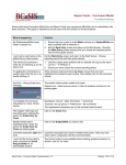
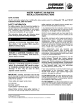
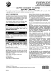
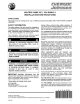
INSTALLATION INSTRUCTIONS
OUTBOARD JET PUMP – SECONDARY SHIFT CABLE
APPLICATION
This instruction sheet is intended to supplement the aftermarket jet pump manufacturer’s installation
instructions. Evinrude® E-TEC™ outboards require a secondary shift cable and hardware to actuate the
powerhead shift linkage when outboard jet pump kit is installed.
SAFETY INFORMATION
For safety reasons, this part should be installed by
an authorized Evinrude®/Johnson® dealer. This instruction sheet is not a substitute for work experience. Additional helpful information may be found
in other service literature for your engine.
This instruction sheet uses the following signal
words identifying important safety messages.
DANGER
Indicates an imminently hazardous situation which, if not avoided, WILL result in
death or serious injury.
WARNING
Indicates a potentially hazardous situation
which, if not avoided, CAN result in severe
injury or death.
CAUTION
Indicates a potentially hazardous situation
which, if not avoided, MAY result in minor
or moderate personal injury or property
damage. It also may be used to alert
against unsafe practices.
IMPORTANT: Identifies information that will
help prevent damage to machinery and appears
next to information that controls correct assembly and operation of the product.
These safety alert signal words mean:
ATTENTION!
BECOME ALERT!
YOUR SAFETY IS INVOLVED!
Always follow common shop safety practices. If
you have not had training related to common shop
safety practices, you should do so to protect yourself, as well as the people around you.
It is understood that this instruction sheet may be
translated into other languages. In the event of any
discrepancy, the English version shall prevail.
DO NOT do any repairs until you have read the instructions and checked the pictures relating to the
repairs.
Be careful, and never rush or guess a service procedure. Human error is caused by many factors:
carelessness, fatigue, overload, preoccupation,
unfamiliarity with the product, and drugs and alcohol use, to name a few. Damage to a boat and outboard can be fixed in a short period of time, but
injury or death has a lasting effect.
When replacement parts are required, use
Evinrude/Johnson Genuine Parts or parts with
equivalent characteristics, including type, strength
and material. Using substandard parts could result
in injury or product malfunction.
Torque wrench tightening specifications must be
strictly followed. Replace any locking fastener
(locknut or patch screw) if its locking feature becomes weak. Definite resistance to turning must be
felt when reusing a locking fastener. If replacement
is specified or required because the locking fastener has become weak, use only authorized
Evinrude/Johnson Genuine Parts.
If you use procedures or service tools that are not
recommended in this instruction sheet, YOU
ALONE must decide if your actions might injure
people or damage the outboard.
TO THE INSTALLER: Give this sheet to the owner.
Advise the owner of any special operation or maintenance information contained in the instructions.
TO THE OWNER: Save these instructions in your
owner’s kit. This sheet contains information important to the future use and maintenance of your outboard.
Printed in the United States
© 2005 BRP US Inc. All rights reserved.
TM, ® Trademarks and registered trademarks of Bombardier Recreational Products Inc. or its affiliates.
DSS05105I
01/05
1 of 5
JET PUMP MOUNTING
MODIFICATION
Use the 2 in. x 3/8 in. screw in the rear mounting
hole of jet pump.
WARNING
To prevent accidental starting while servicing, disconnect the battery cables at the
battery. Twist and remove all spark plug
leads.
Remove jet pump housing exhaust tube retainer
assembly and exhaust tube.
1
Cutaway view
Reinstall exhaust tube in jet pump housing.
SECONDARY SHIFT CABLE
INSTALLATION
CAUTION
1. Exhaust tube
1
Failure to install and adjust the secondary
shift cable will affect outboard operation.
Neutral idle run quality may be adversely
affected and outboard will not accelerate
in gear.
Assemble secondary shift cable components as
follows.
Secure secondary cable (5 ft.) to jet pump cable
bracket with mounting hardware. Install locking
nut and cable end provided. Secure cable end
with locking nut with approximately 1/4 in. of
threads exposed.
1. Retainer assembly
Drill the threaded mounting hole at rear of jet
pump housing to 0.386 in. (25/64 in.)
1
1
2
1. Cable
2. Bracket
1. Rear mounting hole
Refer to appropriate service manual for water
pump installation and gearcase mounting screw
torques. Install jet pump housing on outboard.
2 of 5
Position trunnion in bracket on powerhead.
2
1
3
1
1/4 in
1. Mounting hardware
2. Locking nut
3. Cable end
1. Bracket
Secure cable bracket to jet pump housing and
cable end to shift cam. Position shift cam in
NEUTRAL position as shown.
Adjust cable end (or ends) to position shift
linkage in NEUTRAL position. Neutral detent
must be centered in shift lever detent and neutral
switch must be centered on cam of detent.
Tighten locking nut.
1
1
2
1. Cable bracket
Secure cable trunnion with retainer in end
position as shown. Install locking nut and cable
end provided.
1. Shift lever detent
2. Neutral switch/cam
Secure cable on shift lever pin with flat washer
and retainer clip.
1
1
3
2
1. Cable trunnion w/retainer
2. Locking nut
3. Cable end
1. Flat washer and retainer clip
3 of 5
Verify shift linkage is adjusted properly.
If gate can be moved toward NEUTRAL, readjust
eccentric to hold reverse gate in FORWARD
position.
1
1
1. Neutral switch depressed with shift actuator in
NEUTRAL position
1. FORWARD position
SHIFT GATE ADJUSTMENT
Move remote control handle to NEUTRAL
detent.
Hold reverse gate up and check for proper
clearance between reverse gate and water flow
passage:
• 15/32 in. (11.9 mm)
If adjustment is required:
• Loosen shift cam screw
• Rotate cam eccentric nut while holding
reverse gate up, until proper clearance is
achieved. Tighten cam screw and recheck
adjustment.
SHIFT CABLE ADJUSTMENT
WARNING
The shift cable must be adjusted correctly
or water pressure from forward boat travel
could move the gate into REVERSE, causing the boat to stop abruptly. Occupants
could be thrown about or ejected.
Pull up on shift cam until cam roller is at the far
end of the FORWARD detent range.
1
1
2
4
3
1.
2.
3.
4.
CLEARANCE
Eccentric nut
Reverse gate
Screw
Move remote control handle to FORWARD
detent.
When roller is in FORWARD position, apply hand
pressure to move the reverse gate up, toward
NEUTRAL. If properly adjusted, reverse gate
should not move toward NEUTRAL.
4 of 5
2
1. Shift cam
2. FORWARD detent range
Shift remote control to FORWARD position.
Temporarily push cable guide onto shift cam
stud. Pull firmly on cable casing to remove free
play. Adjust cable trunnion to align with trunnion
bracket. Pull cable off the stud.
Do not restrict movement of shift cables. Route
cables carefully and secure with tie straps.
1
3
2
1. Cable guide
2. Stud
3. Trunnion anchor bracket
Insert cable trunnion in anchor bracket and turn
90° to lock the trunnion in place.
Refer to the appropriate service manual and the
remote control installation instructions for
additional installation information.
Push cable guide onto stud. Install washer and
hand tighten the locknut.
Connect battery cables, positive cable first and
then negative cable. Connect spark plug wires to
spark plugs.
Shift remote control to NEUTRAL. The cam roller
should snap into NEUTRAL detent when you pull
up on the reverse gate with moderate pressure.
Test outboard operation before returning or
delivering to customer.
WARNING
1
The shift cables and linkage must be correctly installed and adjusted. Failure to
correctly install the outboard could result
in property damage, serious injury or
death.
1. NEUTRAL detent
If you cannot achieve NEUTRAL detent,
lengthen cable slightly and recheck your
adjustment.
IMPORTANT: The reverse gate must remain
locked in the FORWARD detent range when remote control is in FORWARD. When properly adjusted, the reverse gate cannot be pulled out of
the FORWARD detent range by hand.
5 of 5