1
www.sauservice.com
1ST PRINTING MAY ‘04
®
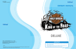
29 inch Deluxe Version
Owner’s Manual
SEGA AMUSEMENTS USA, INC.
MANUAL NO. 999-2026
GAME CODE: OLS
VISIT OUR WEBSITE!
BEFORE USING THE PRODUCT, BE SURE TO READ THE FOLLOWING:
To maintain the safety:
To ensure the safe usage of the product, be sure to read the following before using the product. The
following instructions are intended for the users, operators and the personnel in charge of the operation of the product. After carefully reading and sufficiently understanding the warning displays and
cautions, handle the product appropriately. Be sure to keep this manual nearby the product or elsewhere convenient for referring to it when necessary.
Herein, explanations which require special attention are enclosed with dual lines. Depending on the
potentially hazardous degrees, the terms of WARNING, CAUTION, etc. are used. Be sure to understand the contents of the displays before reading the text.
WARNING!
Indicates that mishandling the product by disregarding this warning
will cause a potentially hazardous
situation which can result in death
or serious injury.
CAUTION!
Indicates that mishandling the product
by disregarding this caution will cause
a slight hazardous situation which can
result in personal injury and or material
damage.
For the safe usage of the product, the following pictographs are used:
Indicates “HANDLE WITH CARE.” In order to protect the human body an equipment,
this display is attached to places where the Owner’s Manual and or Service Manual should
be referred to.
Perform work in accordance with the instructions herein stated.
Instructions for work are explained by paying attention to the aspect of accident prevention. Failing to
perform work as per the instructions can cause accidents. In the case where only those who have technical expertise should perform the work to avoid hazardous situation, the instructions herein state that the
serviceman should perform such work.
Be sure to turn off power before working on the machine.
To prevent electric shock, be sure to turn off power before starting the work in which the worker touches
the interior of the product. If the work is to be performed in the power-on status, the Instruction Manual
herein always states to that effect.
Be sure to ground the Earth Terminal (this, however, is not required in the case where a power cord
with earth is used).
This product is equipped with the Earth Terminal. When installing the product, Connect the Earth Terminal to the “accurately grounded indoor earth terminal” by using an earth wire. Unless the product is
grounded appropriately, the user can be subject to electric shock. After performing repair, etc. for the
Control equipment, ensure that the Earth Wire is firmly connected to the Control equipment.
Ensure that the Power Supply used is equipped with an Earth Leakage Breaker.
This product does not incorporate the Earth Leakage Breaker. Using a power supply which is not
equipped with the Earth Leakage Breaker can cause a fire when earth leakage occurs.
Be sure to use fuses which meet the specified rating. (only for the machines which use fuses).
Using fuses exceeding the specified rating can cause a fire and electric shock.
Specification changes (removal of equipment, conversion and addition) not designated by SEGA
are not allowed.
The parts of the product include warning labels for safety, covers for personal protection, etc. It is
very hazardous to operate the product by removing parts and or modifying the circuits. Should doors,
lids and protective parts be damaged or lost, refrain from operating the product, and contact where the
product was purchased from or the office herein stated. SEGA shall not be held responsible for any
accidents, compensation for damage to a third party, resulting from the specifications not designated by
SEGA.
Ensure that the product meets the requirements of appropriate Electrical Specifications.
Before installing the product, check for Electrical Specifications. SEGA products have a nameplate
on which Electrical Specifications are described. Ensure that the product is compatible with the power
supply voltage and frequency requirements of the location. Using any Electrical Specifications different
from the designated Specifications can cause a fire and electric shock.
Install and operate the product in places where appropriate lighting is available, allowing warning
labels to be clearly read.
To ensure safety for the customers, labels and printed instructions describing potentially hazardous situation are applied to places where accidents can be caused. Ensure that where the product is operated
has sufficient lighting allowing the warnings to be read. If any label is peeled off, apply it again immediately. Please place an order with where the product was purchased from or the office herein stated.
When handling the Monitor, be very careful. (Applies only to the product w/monitor.)
Some of the monitor (TV) parts are subject to high tension voltage. Even after running off power, some
portions are still subject to high tension voltage sometimes. Monitor repair and replacement should be
performed only be those technical personnel who have knowledge of electricity and technical expertise.
Be sure to adjust the monitor (projector) properly. (Applies only to the product w/monitor.)
Do not operate the product leaving on-screen flickering or blurring as it is. Using the product with the
monitor not properly adjusted may cause dizziness or a headache to an operator, a player, or the customers.
When transporting or reselling this product, be sure to attach this manual to the product.
In the case where commercially available monitors and printers are used in this product, only the contents relating to this product are explained herein. Some commercially available equipment has functions and reactions not stated in this manual. Read this manual together with the specific Instruction
Manual of such equipment.
• Descriptions herein contained may be subject to improvement changes without notice.
• The contents described herein are fully prepared with due care. However, should any question arise or
errors be found, please contact SEGA.
INSPECTIONS IMMEDIATELY AFTER TRANSPORTING THE PRODUCT TO THE LOCATION.
Normally, at the time of shipment, SEGA products are in a status allowing for usage immediately after
transporting to the location. Nevertheless, an irregular situation may occur during transportation. Before
turning on power, check the following points to ensure that the product has been transported in a satisfactory status.
Are there any dented portions or defects (cuts, etc.) on the external surfaces of the cabinet?
Are Casters and Adjusters, damaged?
Do the power supply voltage and frequency requirements meet with those of the location?
Are all wiring connectors correctly and securely connected? Unless connected in the correct direction,
connector connections can not be made accurately. Do not insert connectors forcibly.
Do power cords have cuts and dents?
Do the fuses used meet specified rating? Is the Circuit Protector in an energized status?
Are all accessories available?
Can all Doors and Lids be opened with the Accessory keys? Can Doors and Lids be firmly closed?
TABLE OF CONTENTS
BEFORE USING THE PRODUCT, BE SURE TO READ THE FOLLOWING:
TABLE OF CONTENTS
INTRODUCTION OF THE OWNER’S MANUAL
1. HANDLING PRECAUTIONS ..........................................................................................
2. PRECAUTIONS CONCERNING INSTALLATION LOCATION ...................................
3. PRECAUTIONS REGARDING PRODUCT OPERATION .............................................
4. PART DESCRITIONS .......................................................................................................
5. ACCESSORIES .................................................................................................................
6. ASSEMBLING AND INSTALLATION ............................................................................
7. PRECAUTIONS TO BE HEEDED WHEN MOVING THE MACHINE ........................
8. GAME DESCRIPTION .....................................................................................................
9. EXPLANATION OF TEST AND DATA DISPLAY .........................................................
9 - 1 SWITCH UNIT AND COIN METER ............................................................
9 - 2 SYSTEM TEST MODE ..................................................................................
9 - 3 GAME TEST MODE ......................................................................................
10. MAINTENCE OF SKATEBOARD MECHANISM UNIT ...............................................
10 - 1 ADJUSTING/REPLACING THE TILT DETECTION VOLUME CONTR
10 - 2 GREASING ....................................................................................................
10 - 3 REPLACING THE BELLOWS ....................................................................
11. COIN SELECTOR ............................................................................................................
12. MONITOR ........................................................................................................................
13. REPLACING THE FLOURESCENT LAMP/OTHER LAMPS ......................................
14. PERIODIC INSPECTION TABLE ..................................................................................
15. TROUBLESHOOTING ....................................................................................................
16. GAME BOARD ................................................................................................................
16 - 1 REMOVING THE GAME BOARD ..............................................................
16 - 2 REMOVING THE GD-ROM DRIVE ...........................................................
16 - 3 COMPOSITION OF GAME BOARD ...........................................................
16 - 4 REPLACING THE MAIN BOARD BATTERY ............................................
16 - 5 REPLACING THE MEDIA BOARD BATTERY PACK ..............................
16 - 6 SHIPPING THE GAME BOARD AND CARTON BOX ..............................
17. NETWORK PLAY ............................................................................................................
17 - 1 PRECAUTIONS REGUARDING NETWORK PLAY SETUP ...................
17 - 2 CONNECTING NETWORK CABLES .......................................................
17 - 3 NETWORK PLAY SETTINGS ...................................................................
17 - 4 GENERAL PRECAUTIONS REGARDING NETWORK PLAY .................
18. DESIGN RELATED PARTS ...........................................................................................
19. PARTS LIST ...................................................................................................................
20. WIRE COLOR CODE TABLE ........................................................................................
21. WIRING DIAGRAM .......................................................................................................
1
3-4
5 - 11
12 13 - 14
15 - 35
36 - 37
38 - 47
48 - 73
50
51 - 63
64 - 73
74 - 82
75 - 78
79
80 - 82
83 - 84
85 - 87
88 - 90
91 - 92
93 - 97
98 - 114
99 - 105
106
107
108
109 - 111
112 - 114
115 - 122
115 - 116
117 - 120
121 - 122
122
123
124 - 138
139
XXX
Installation Space
Height
Width
Length
Weight
Power, maximum current
MONITOR
SPECIFICATIONS
:
:
:
:
:
:
32.8 inches width X 87.4 inches depth
84 inches
32.8 inches
87.4 inches
634.9 lbs
336 W 3.44 A (AC 120V 60 Hz AREA)
: 29 inch supplied by Sanwa
Monitor Part# 998-0162
Chassis Part# 998-0161
INTRODUCTION OF THE OWNERS MANUAL
This Owner's Manual is intended to provide detailed descriptions together with all the
necessary information covering the general operation of electronic assemblies, electromechanicals, servicing control, spare parts, etc. as regards the product,
OLLIE KING 29INCH DELUXE TYPE.
This manual is intended for the owners, personnel and managers in charge of operation
of the product. Operate the product after carefully reading and sufficiently understanding the instructions. If the product fails to function satisfactorily, non-technical personnel
should under no circumstances touch the internal system. Please contact where the product was purchased from.
Use of this product is unlikely to cause physical injuries or damages to property. However,
where special attention is required this is indicated by a thick line, the word "IMPORTANT"
and its sign in this manual.
STOP
Indicates that mishandling the product by disregarding this display can cause the
product's intrinsic performance not to be obtained, resulting in malfunctioning.
IMPORTANT!
SEGA AMUSEMENTS USA, INC. / CUSTOMER SERVICE
45133 Industrial Drive, Fremont, California 94538, U.S.A.
Phone : (415) 701-6580
Fax : (415) 701-6594
DEFINITION OF LOCATION MAINTENANCE MAN AND SERVICEMAN
WARNING!
Non-technical personnel who do not have technical knowledge and expertise should
refrain from performing such work that this manual requires the location's maintenance man or a serviceman to carry out, or work which is not explained in this
manual. Failing to comply with this instruction can cause a severe accident such
as electric shock.
Ensure that parts replacement, servicing & inspections, and troubleshooting are performed by the
location's maintenance man or the serviceman. It is instructed herein that particularly hazardous work
should be performed by the serviceman who has technical expertise and knowledge.
The location's maintenance man and serviceman are herein defined as follows:
"Location's Maintenance Man" :
Those who have experience in the maintenance of amusement equipment and vending machines, etc.,
and also participate in the servicing and control of the equipment through such routine work as equipment assembly and installation, servicing and inspections, replacement of units and consumables, etc.
within the Amusement Facilities and or locations under the management of the Owner and Owner's
Operators of the product.
Activities of Location's Maintenance Man :
Assembly & installation, servicing & inspections, and replacement of units & consumables as regards
amusement equipment, vending machines, etc.
Serviceman :
Those who participate in the designing, manufacturing, inspections and maintenance service of the
equipment at an amusement equipment manufacturer.
Those who have technical expertise equivalent to that of technical high school graduates as regards
electricity, electronics and or mechanical engineering, and daily take part in the servicing & control
and repair of amusement equipment.
Serviceman's Activities :
Assembly & installation and repair & adjustments of electrical, electronic and mechanical parts of
amusement equipment and vending machines.
LISTED
UL
®
5K92
AMUSEMENT MACHINE
Notes:
1. HANDLING PRECAUTIONS
When installing or inspecting the machine, be very careful of the following points and pay attention to
ensure that the player can enjoy the game safely.
Non-compliance with the following points or inappropriate handling running counter to the cautionary
matters herein stated can cause personal injury or damage to the machine.
WARNING!
● Before performing work, be sure to turn power off. Performing the work without
turning power off can cause an electric shock or short circuit. In the case work
should be performed in the status of power on, this manual always states to that effect.
● To avoid electric shock or short circuit, do not plug in or unplug quickly.
● To avoid electric shock, do not plug in or unplug with a wet hand.
● Do not expose Power Cords and Earth Wires on the surface, (floor, passage, etc.).
If exposed, the Power Cords and Earth Wires are susceptible to damage. Damaged
cords and wires can cause electric shock or short circuit.
● To avoid causing a fire or electric shock, do not put things on or damage Power
Cords.
● When or after installing the product, do not unnecessarily pull the power cord. If
damaged, the power cord can cause a fire or electric shock.
● In case the power cord is damaged, ask for replacement through where the product
was purchased from or the office herein stated. Using the cord as is damaged can
cause fire, electric shock or leakage.
● Be sure to perform grounding appropriately. Inappropriate grounding can cause an
electric shock.
● Be sure to use fuses meeting specified rating. Using fuses exceeding the specified
rating can cause a fire or electric shock.
● Completely make connector connections for IC BD and others. Insufficient insertion can cause an electric shock.
● Specification changes, removal of equipment, conversion and/or addition, not designated by SEGA are not permitted.
• Failure to observe this may cause a fire or an electric shock. Non-compliance with
this instruction can have a bad influence upon physical conditions of the players or
the lookers-on, or result in injury during play.
• SEGA shall not be held responsible for damage, compensation for damage to a third
party, caused by specification changes not designated by SEGA.
● Be sure to perform periodic maintenance inspections herein stated.
1
www.seuservice.com
STOP
IMPORTANT!
● For the IC board circuit inspections, only the logic tester is allowed. The use of a
multiple-purpose tester is not permitted, so be careful in this regard.
● The Projector is employed for this machine. The Projector's screen is susceptible
to damage, therefore, be very careful when cleaning the screen. For details, refer to
PROJECTOR.
● Static electricity from your body may damage some electronics devices on the IC
board. Before handling the IC board, touch a grounded metallic surface so that the
static electricity can be discharged.
● Some parts are the ones designed and manufactured not specifically for this game
machine. The manufacturers may discontinue, or change the specifications of, such
general-purpose parts. If this is the case, Sega cannot repair or replace a failed game
machine whether or not a warranty period has expired.
www.seuservice.com
2
2. PRECAUTIONS REGARDING INSTALLATION LOCATION
WARNING!
This product is an indoor game machine. Do not install it outside. Even indoors, avoid
installing in places mentioned below so as not to cause a fire, electric shock, injury and
or malfunctioning.
● Places subject to rain or water leakage, or places subject to high humidity in the
proximity of an indoor swimming pool and or shower, etc.
● Places subject to direct sunlight, or places subject to high temperatures in the proximity of heating units, etc.
● Places filled with inflammable gas or vicinity of highly inflammable/volatile chemicals or hazardous matter.
● Dusty places.
● Sloped surfaces.
● Places subject to any type of violent impact.
● Vicinity of anti-disaster facilities such as fire exits and fire extinguishers.
● The operating (ambient) temperature range is from 5˚ to 30˚.
LIMITATIONS OF USAGE REQUIREMENTS
WARNING!
● Be sure to check the Electrical Specifications.
Ensure that this product is compatible with the location's power supply, voltage and
frequency requirements.
A plate describing Electrical Specifications is attached to the product.
Non-compliance with the Electrical Specifications can cause a fire and electric shock.
● This product requires the Breaker and Earth Mechanisms as part of the location facilities. Using them in a manner not independent can cause a fire and electric shock.
● Ensure that the indoor wiring for the power supply is rated at 5 A or higher (AC
single phase 100~120 V area), and 3 A or higher (AC 220~240 V area). Non-compliance with the Electrical Specifications can cause a fire and electric shock.
● Be sure to independently use the power supply equipped with the Earth Leakage
Breaker. Using a power supply without the Earth Leakage Breaker can cause an
outbreak of fire when earth leakage occurs.
● Putting many loads on one electrical outlet can cause generation of heat and a fire
resulting from overload.
● When using an extension cord, ensure that the cord is rated at 5 A or higher (AC
100~120 V area) and 3 A or higher (AC 220~240 V area). Using a cord rated lower
than the specified rating can cause a fire and electric shock.
3
www.seuservice.com
OPERATION AREA
WARNING!
STOP
IMPORTANT!
● For the operation of this machine, secure a minimum area of 1.8 m (W)×2.5 m (D).
In order to prevent injury resulting from the falling down accident during game
play, be sure to secure the minimum area for operation.
● Be sure to provide sufficient space so as to allow this product's ventilation fan to
function efficiently. To avoid machine malfunctioning and a fire, do not place any
obstacles near the ventilation opening.
● SEGA shall not be held responsible for damage, compensation for damage to a
third party, resulting from the failure to observe this instruction.
For transporting the machine into the location's building, the minimum necessary dimensions of the opening (of doors, etc.) are 0.85 m (W) and
1.8 m (H).
Electric current consumption
MAX. 3.44 A (AC 120 V, 60 Hz)
MAX. 1.86 A (AC 220 V, 50 Hz)
MAX. 1.83 A (AC 220 V, 60 Hz)
MAX. 1.71 A (AC 240 V, 50 Hz)
MAX. 3.6 A (AC 110 V, 60 Hz,
For TAIWAN)
2.5 m (98 in)
1.8 m (71 in)
10 cm (4 in)
FIG. 2
www.seuservice.com
4
***Note: Actual Main unit WILL differ from image.
3. PRECAUTIONS REGARDING PRODUCT OPERATION
BEFORE OPERATION
To avoid injury and trouble, be sure to constantly give careful attention to the behavior and manner of the
visitors and players.
In order to avoid accidents, check the following before starting the operation:
WARNING!
● To ensure maximum safety for the players and the customers, ensure that where the
product is operated has sufficient lighting to allow any warnings to be read. Operation under insufficient lighting can cause bodily contact with each other, hitting accident, and or trouble between customers.
● Be sure to perform appropriate adjustment of the monitor (projector). For operation of this machine, do not leave monitor's flickering or deviation as is. Failure to
observe this can have a bad influence upon the players' or the customers' physical
conditions.
● It is suggested to ensure a space allowing the players who feel sick while playing the
game to take a rest.
● Check if all of the adjusters are in contact with the surface. If they are not, the Cabinet can move and cause an accident.
Ensure that all of the Adjuster
in contact with the floor.
***Note: Actual Main unit WILL differ from image.
● Check that the safety parts are in good condition and securely attached. Accidents
may occur if this product is operated with defective safety parts.
5
www.seuservice.com
WARNING!
● Perform a test run. Check that there are no defects in
the following parts.
Is the safety bar attached securely
without any slack or free-movement?
Are the side panels undamaged
and attached securely?
***Note: Actual Main unit WILL differ from image.
Are the bellows in good condition?
● Do not put any heavy item on this product. Placing any heavy item on the product
can cause a falling down accident or parts damage.
● Do not climb on the product. Climbing on the product can cause falling down
accidents. To check the top portion of the product, use a step.
● To avoid electric shock, check to see if door & cover parts are damaged or omitted.
● To avoid electric shock, short circuit and or parts damage, do not put the following
items on or in the periphery of the product.
Flower vases, flowerpots, cups, water tanks, cosmetics, and receptacles/containers/
vessels containing chemicals and water.
CAUTION!
To avoid injury, be sure to provide sufficient space by considering the potentially
crowded situation at the installation location. Insufficient installation space can cause
making bodily contact with each other, hitting accidents, and or trouble between customers.
www.seuservice.com
6
DURING OPERATION (PAYING ATTENTION TO CUSTOMERS)
To avoid injury and trouble, be sure to constantly give careful attention to the behavior and manner of the
visitors and players.
WARNING!
● To avoid injury and accidents, those who fall under the following categories are not
allowed to play the game.
• Those who need assistance such as the use of an apparatus when walking.
• Those who have high blood pressure or a heart problem.
• Those who have experienced muscle convulsion or loss of consciousness when playing
video game, etc.
• Those who have a trouble in the neck and or spinal cord.
• Intoxicated persons.
• Pregnant women or those who are in the likelihood of pregnancy.
• Persons susceptible to motion sickness.
• Persons whose act runs counter to the product's warning displays.
● A player who has never been adversely affected by light stimulus might experience
dizziness or headache depending on his physical condition when playing the game.
Especially, small children can be subject to those conditions. Caution guardians of
small children to keep watch on their children during play.
● Instruct those who feel sick during play to have a medical examination.
● To avoid injury resulting from falling down and electric shock due to spilled drinks,
instruct the player not to place heavy items or drinks on the product.
● To avoid electric shock and short circuit, do not allow customers to put hands and
fingers or extraneous matter in the openings of the product or small openings in or
around the doors.
● To avoid falling down and injury resulting from falling down, immediately stop the
customer's leaning against or climbing on the product, etc.
● To avoid electric shock and short circuit, do not allow the customers to unplug the
power plug without a justifiable reason.
● Only players who satisfy the
minimum height requirement and
can hold the safety bar correctly
while riding the skateboard may
play.
Warn persons below the minimum
height requirement of 1.3m that
they are prohibited from playing.
Do not allow anyone to play
unless they hold the safety bar at
all times.
7
www.seuservice.com
WARNING!
● Warn anyone wearing high heel shoes that they are prohibited
from playing since there is a high risk of injury from accidents.
● Similarly, warn anyone wearing sandals or other easily removed shoes that they are
prohibited from playing since there is a high risk of injury from accidents.
● To avoid injury from potential falling down
accidents, be sure to instruct that only one
person is allowed to play at a time.
● Do not allow players to put any heavy
item or beverages on the product. Falling
down items can cause accidents and spilled
beverages can cause electric shock.
www.seuservice.com
8
● Instruct the player to hold on firmly to the Safety Bar during game. Caution the
customers who are most likely to cause injury by playing without holding the Safety
Bar, for example.
● To avoid injury, do not allow
persons other than the player to
access to the Rear Cabi during
game play.
❖ Instruct the player to play by
standing on both feet. Standing
on one leg to play can cause
injury.
9
www.seuservice.com
● Instruct the player not to put baggages, etc. on
the Rear Cabi to avoid damaging such items.
● Regarding this product, the weight of the
player is limited to 387 lbs. To avoid machine
damage and injury due to machine damage,
playing by those who are as heavy as 287 lbs.
or heavier is strictly prohibited.
● Immediately stop such violent acts as hitting and kicking the product. Such violent
acts can cause parts damage or falling down, resulting in injury due to fragments and
falling down.
www.seuservice.com
10
STOP
IMPORTANT!
● This product requires certain measures to prevent causing disruption to other nearby
game machines, etc. Playing this machine may hinder the operation of nearby game
machines due to vibration, etc. Fit the leg rubbers to the bottom of the adjuster feet,
and avoid setting up on wooden floorings.
● This product may scratch the floor surface of the installation site. If the floor surface
is wooden floorboards or carpeting, consider using a rubber mat or some other
means to protect the floor.
● Please take care not to offend or disturb customers when the machine is removed or
relocated to other places.
LEG RUBBER
(Accessories)
***Note: Actual Main unit WILL differ from image.
RUBBER MAT (For floor protection
(Sold separately)
11
www.seuservice.com
4. PART DESCRIPTIONS
BILLBOARD
29 TYPE MONITOR
CONTROL PANEL
SPEAKER
SAFETY BAR
FRONT CABINET
REAR CABINET
COIN CHUTE DOOR
CASHBOX DOOR
SERVICE DOOR
FIG. 4 a OVERVIEW
***Note: Actual Main unit WILL differ from image.
SKATEBOARD
REAR HATCH
AC UNIT
COMMUNICATION PORT
FIG. 4 c REAR VIEW
ASSEMBLY (ASSY) TUBE
ASSEMBLY (ASSY) TUBE
FIG. 4 b
TABLE 4 Dimensions and Weights
Width ×
Depth × Height
FRONT CABINET
30 in ×
37 in ×
70 in
357 lbs
BILLBOARD
30 in ×
11 in × 16.6 in
16.5 lbs
REAR CABINET
33 in ×
49 in ×
45 in
260 lbs
FINAL PRODUCT
33 in ×
87 in ×
84 in
635 lbs
www.seuservice.com
12
Weight
5. ACCESSORIES
When transporting the machine, make sure that the following parts are supplied.
TABLE 5 a ACCESSORIES
DESCRIPTION
Part No. (Qty.)
Notes
OWNER'S MANUAL
999-2026
This manual
Figures
Parts not labeled with part numbers are as yet
unregistered or cannot be registered. Be sure to
handle all parts with care, as some parts are not
available for purchase separately.
CARTON BOX
601-11219-01 (1)
.
KEY MASTER
220-5576 (2)
For opening/closing
the doors
TAMPERPROOF WRENCH
M3 Torx Wrench (1)
Tool
KEY
(2)
For the CASHBOX DOOR
The Keys are inside the Coin
Chute Door at the time of shipment from the factory.
AC Cable (Power Cord)
600-7228
600-6618 (1) AC 220~240V AREA
ASSY FIBER CABLE (NETWORK CABLE) 5 m
600-7269-0500 (1)
ASSY FIBER CABLE (NETWORK CABLE) 2 m
600-7269-0200 (1)
13
www.seuservice.com
GD SOFT KIT OLS
Software
CUSHION SPONGE
601-11137
GD-ROM Disc Protector
GD-ROM DISC
DISC CASE
253-5507
www.seuservice.com
14
6. ASSEMBLY AND INSTALLATION
WARNING!
CAUTION!
● Perform assembly work by following the procedure herein stated. Failing to
comply with the instructions can cause electric shock hazard.
● Perform assembling as per this manual. Since this is a complex machine, erroneous
assembling can cause an electric shock, machine damage and or not functioning as
per specified performance.
● When assembling, be sure to use plural persons. Depending on the assembly work,
there are some cases in which working by one person alone can cause personal
injury or parts damage.
● Ensure that connectors are accurately connected. Incomplete connections can cause
electric shock hazard.
● Be careful not to damage the wires. Damaged wires may cause electric shock or
short circuit or present a fire risk.
● This work should be performed by the site maintenance individual or other skilled
professional. Performing work by non-technical personnel can cause a severe
accident such as electric shock. Failing to comply with this instruction can cause a
severe accident such as electric shock to the player during operation.
● Provide sufficient space so that assembling can be performed. Performing work in
places with narrow space or low ceiling may cause an accident and assembly work
to be difficult.
● To perform work safely and avoid serious accident such as the cabinet's falling
down, do not perform work in places where step-like grade differences, a ditch, or
slope exist.
● Handle molded parts with care. Undue weight or pressure may cause them to break
and the broken pieces may cause injury.
● To perform work safely and securely, be sure to prepare a step which is in a secure
and stable condition. Performing work without using the step can cause violent
falling down accidents.
● Make sure that the GD cable connector is inserted parallel to the plug. Improper
insertion may cause damage to the connector and present a fire risk.
15
www.seuservice.com
STOP
IMPORTANT!
● We recommend that the product is assembled at the proposed site of operation.
If there is any difference between the place of assembly and operation, it will
be necessary to dismantle and reassemble the product. Read section 7 for the
precautions regarding moving the machine.
● This product requires certain measures to prevent causing disruption to other nearby
game machines, etc. Playing this machine may hinder the operation of nearby game
machines due to vibration, etc. Fit the leg rubbers to the bottom of the adjuster feet,
and avoid setting up on wooden floorings.
● This product may scratch the floor surface of the installation site. If the floor surface
is wooden floorboards or carpeting, consider using a rubber mat or some other means
to protect the floor.
www.seuservice.com
16
REQUIRED TOOLS, IMPLEMENTS
Master key
Phillips head screwdriver (M5, M4 screws)
24 mm
24-mm spanner
Short Phillips head screwdriver (M5 screws)
When carrying out the assembling and installation, follow the following 7-item sequence.
1
CABINET-TO-CABINET CABLE CONNECTIONS
2
SECURING IN PLACE(ADJUSTER ADJUSTMENT)
3
INSTALLING THE GD-ROM DRIVE(SETTING GD-ROM DISC)
4
POWER SUPPLY, AND EARTH CONNECTION
5
TURNING POWER ON
6
ASSEMBLING CHECK
17
www.seuservice.com
1
WARNING!
CABINET-TO-CABINET CABLE CONNECTIONS
● Ensure that connectors are accurately connected. Incomplete connections can cause
electric shock hazard.
● Be careful not to damage the wires. Damaged wires may cause electric shock or
short circuit or present a fire risk.
Connect the cables between both cabinets by attaching the assembly tube to the front cabinet and rear
cabinet.
The matching connectors have the same number of pins and, therefore, can only be connected in one
direction. Avoid forcibly inserting the connectors as this may cause damage to the pins and cables.
At one end of the assembly tube there is a circular earth wire terminal. The tube end with the earth terminal connects to the rear cabinet side.
FRONT CABINET SIDE
PHOTO 6. 2 a
EARTH WIRE TERMINAL
REAR CABINET SIDE
● Remove the plastic locking nut from the front cabinet end of the assembly tube.
● Using the master key, unlock and detach the front cabinet service door.
SERVICE DOOR
PHOTO 6. 2 b
www.seuservice.com
18
● Feed the assembly tube wires
through the hole in the bottom of the
front cabinet floor panel, insert the
end connector and lock in place by
tightening the plastic locking nut.
Be careful to avoid pinching the wires
when doing this.
PHOTO 6. 2 c
***Note: Actual Main unit WILL differ from image.
● Connect the assembly tube cable
connector to the connector inside the
front cabinet.
Fasten the connector.
PHOTO 6. 2 d
***Note: Actual Main unit WILL differ from image.
● From the rear cabinet, detach the front
floor sash facing the front cabinet.
Remove the three truss screws.
TRUSS SCREW (3), black
M4×12
PHOTO 6. 2 e
19
www.seuservice.com
● Remove the two truss screws and detach the floor side sashes locking the left and right sides of the rear
cabinet floor design sheet. The left and right side floor side sash components are different. Be careful to
return these to their correct original positions.
FLOOR SIDE SASH
TRUSS SCREW (2ea), black
M4×25
PHOTO 6. 2 f
● Pull up the floor design sheet carefully
to reveal the tube mount lid.
FLOOR DESIGN SHEET
TUBE MOUNT LID
PHOTO 6. 2 g
● Remove the four flat head screws
locking the tube mount lid and detach
the lid.
FLAT HEAD SCREW (4)
M4×12
PHOTO 6. 2 h
www.seuservice.com
20
● Remove the plastic locking nut from
the rear cabinet end connector of the
assembly tube.
● Feed the assembly tube wires through
the hole in the bottom of the rear
cabinet floor panel, insert the end
connector and lock in place by
tightening the plastic locking nut.
Be careful to avoid pinching the wires
when doing this.
PHOTO 6. 2 i
***Note: Actual Main unit WILL differ from image.
● Next to the hole in the rear cabinet
floor panel there is a stud for
tightening the circular earth wire
terminal. Insert the circular earth
wire terminal, flat washer, and spring
washer in that order and then tighten
with the hexagon locking nut.
HEXAGON NUT (1)
M4 flat & spring washers used
PHOTO 6. 2 j
***Note: Actual Main unit WILL differ from image.
● Connect the assembly tube cable
connector to the connector inside the
rear cabinet.
Fasten the connector.
PHOTO 6. 2 k
***Note: Actual Main unit WILL differ from image.
21
www.seuservice.com
● Lock the tube mount lid in position using the four flat head screws. Attach the floor side sashes to the left
and right sides of the floor design sheet and lock in position with the two truss screws. The left and right
side floor side sash components are different.
● Attach the front floor sash and lock in position with the three truss screws.
● Attach the front cabinet front service door and lock it.
***Note: Actual Main unit WILL differ from image.
PHOTO 6. 2 l
www.seuservice.com
22
2
WARNING!
SECURING IN PLACE (ADJUSTER ADJUSTMENT)
Make sure that all of the adjusters are in contact with the floor. If they are not, the cabinet can move and cause an accident.
On the floor panel of the front cabinet there are four casters
and two adjuster feet. On the rear cabinet floor panel there
are four casters and four adjuster feet.
Transport the product to the installation site. When you
have decided the product orientation and position, adjust
the adjuster feet until they are in direct contact with the
floor surface and the product remains horizontal.
***Note: Actual Main unit WILL differ from image.
ADJUSTER
● Transport the product to the installation position.
Leave a space of 100mm between the rear panel of the
front cabinet and the wall surface.
CASTER
FIG. 6. 3 a BOTTOM VIEW
● Leave a space of 30mm between the front cabinet and rear cabinet.
● Using a spanner, adjust each of the adjuster feet until they are all in direct contact with the floor surface
and the product is horizontal. Where the floor surface is level, the product is set horizontal when the
distance between the front casters on the front cabinet and the floor surface is adjusted to 7mm.
● If there is a possibility of vibration interfering with other nearby game machines, use the accessory leg
rubbers between the rear cabinet adjuster feet and the floor surface.
LEG RUBBER
5mm
100mm
30mm
***Note: Actual Main unit WILL differ from image.
7mm
FIG. 6. 3 b
23
www.seuservice.com
● After making adjustment, fasten the adjuster nut upward and secure the height of adjuster.
ADJUSTER
CASTER
Fasten upward.
Approx. 5m
ADJUSTER
FIG. 6. 3 c
FIG. 6. 3 d
Refer to this Fig. (Scale:1/100)
for the layout of the place of
installation.
***Note: Actual Main unit WILL differ from image.
www.seuservice.com
24
3
INSTALLING THE GD-ROM DRIVE (SETTING GD-ROM DISC)
STOP
IMPORTANT!
● Carefully handle the GD-ROM drive so as not to contaminate the disc and the
readout lens with stains and dust particles.
● Do not continue to use the scratched GD-ROM disc. The scratched GD-ROM disc
may cause the system to malfunction.
● Set the GD-ROM disc onto the GD-ROM drive with its labeled side facing upward.
● The key chip is a precision device. Handle it carefully and avoid exposure to heat,
shock and static electricity, as these may cause damage to the device.
● The key chip is contained in the GD-ROM disc case. Always use them as a set.
● Unpack the shipping crate, and
take out the GD-ROM drive,
GD-ROM drive bracket, and
GD-ROM disc.
GD-ROM DRIVE
GD DRIVE BRACKET
PHOTO 6. 4 a
● Use the 4 tapping screws to fix the GD-ROM drive bracket onto the GD-ROM drive. Be careful about a
fixing direction.
TAPPING SCREW (4)
4×10
GD DRIVE BRACKET
FIG. 6. 4 b
CAUTION for U. S. A., Europe, and Australia:
Attach the 2 caution stickers for a laser ray onto
the GD-ROM drive.
GD-ROM DRIVE
FIG. 6. 4 a
25
www.seuservice.com
● Remove the 1 truss head screw that
fixes the GD-ROM drive lid (DISC
LID). And turn clockwise the lid to
remove.
TRUSS SCREW (1)
M3×8
PHOTO 6. 4 b
● Set the GD-ROM disc onto the GD-ROM drive with its labeled side facing upward.
● Return the lid to its original place, and fix it with 1 truss head screw. Be careful not to fasten the screw
too tightly.
PHOTO 6. 4 c
TRUSS SCREW (1)
M3×8
www.seuservice.com
26
● Using the master key, unlock and detach the
front cabinet rear hatch.
● Release the cord clamp locking the LAN cable
connected to the hub, and disconnect the LAN
cable from the hub.
● Disconnect the hub power plug from the power
socket.
HUB
PHOTO 6. 4 d
Disconnect the hub power plug.
Remove the LAN cable.
Release the cor
d clamp.
PHOTO 6. 4 e
● Loosen the four screws locking the hub base on which the hub is mounted.
● Slide the hub base forward and simply raise the screw heads.
Next, withdraw the hub base from the rear of the cabinet.
Be careful not to snag or damage the wires or LAN cable.
Loosen4 screws.
HUB BASE
PHOTO 6. 4 f
27
www.seuservice.com
● Install the GD-ROM drive on the rear panel
of the Chihiro board. Position the GD-ROM
drive connector panel toward the right side
facing the cabinet rear panel.
● Use 3 screws to attach the GD-ROM Drive.
SCREW (3)
M4×16, w/flat & spring washers
PHOTO 6. 4 g
● Insert both the GD cable connector (for data transmission)
and the power cord connector (JSTNH6P) into the GDROM Drive. Be careful about the insertion direction in this
instance. Make sure that the connectors are inserted firmly
and completely.
POWER CORD CONNECTOR
GD CABLE CONNECTOR
PHOTO 6. 4 h
● Lock the hub base in its original position. Insert the hub power plug into the power socket, insert the
LAN cable into the hub port, and then lock the LAN cable with the cord clamp.
● Reinstall and lock the rear hatch.
www.seuservice.com
28
4
WARNING!
POWER SUPPLY, AND EARTH CONNECTION
● Be sure to independently use the power supply socket outlet equipped with an Earth
Leakage Breaker. Using a power supply without an Earth Leakage Breaker can
cause a fire when electric leakage occurs.
● Ensure that the "accurately grounded indoor earth terminal" and the earth wire
cable are available (except in the case where a power cord plug with earth is used).
This product is equipped with the earth terminal. Connect the earth terminal and
the indoor earth terminal with the prepared cable. If the grounding work is not
performed appropriately, customers can be subjected to an electric shock, and the
product's functioning may not be stable.
● Ensure that the power cord and earth wire are not exposed on the surface (passage,
etc.). If exposed, they can be caught and are susceptible to damage. If damaged,
the cord and wire can cause electric shock and short circuit accidents. Ensure that
the wiring position is not in the customer's passage way or the wiring has protective
covering.
● After wiring power cord on the floor, be sure to protect the power cord. Exposed
power cord is susceptible to damage and causes an electric shock accident.
The AC Unit is mounted on the rear of the machine. The AC Unit has Circuit Protector, Main SW, Earth
Terminal and the Inlet which connects the Power Cord.
● Ensure that the Main SW is OFF.
INLET
CIRCUIT PROTECTOR
Main SW off
EARTH TERMINAL <For Taiwan>
Connect with the indoor earth termin
MAIN SW
FIG. 6. 5 a AC unit
***Note: Actual Unit May Differ From Image.
29
www.seuservice.com
● Connect one end of the earth wire to the AC Unit earth terminal,
and the other end to the indoor earth terminal. The AC Unit earth
terminal has a Bolt and Nut combination. Take off the Nut, pass
the earth wire through the Bolt, and fasten the Nut. <For Taiwan>
Connect the Earth Wire
to the Earth Terminal.
*Note that the Earth Wire is incorporated in the Power Cord for
the Areas of AC 120V (USA) and AC 220~240V, and therefore,
this procedure is not necessary.
FIG. 6. 5 b *Earth Wire Connection
● Firmly insert the power plug into the socket
outlet.
Insert the opposite side of Power Cord plug to the
AC Unit's connector ("INLET").
● Perform wiring for the Power Cord and Earth
Wire. Install protective covering for the Power
Cord and Earth Wire.
WIRING COVER
FIG. 6. 5 c Connecting Power Cord and Earth Wire
In case the Power Plug is apt to come out of place, secure the Power Cord
to the periphery of the AC Unit with the Cord Clamp (an accessory).
FIG. 6. 5 d HOW TO USE THE CORD CLAMP
www.seuservice.com
30
5
TURNING POWER ON
In this product, the main switch is in the AC unit and the Sub Power switch is inside the service door. The
power is not turned on unless the both switches are on.
Switch on the power. The Billboard fluorescent lamp and cold-cathode tube turn on. After the monitor displays the Chihiro initialization screen, the product enters "Advertising" mode (waiting for player
mode). At the same time, sound is output from the left and right control panel speakers and from the
super woofer. However, the sound is canceled if the product is set not to output the sound in "Advertising" mode.
This product retains the number of credits, the ranking data and the settings in the Test Mode even after
the power is turned off. It does not retain data about the fractional number of coins (i.e., the number of
coins not reaching one credit) or the bonus adder count.
Accordingly, if the power is switched off before play has ended when there were any credits remaining,
when the power is switched back on, the start button light flashes on and off.
Fluorescent lamp is lit.
Cold-cathode tube is lit.
Sound is emitted.
On-screen images are output
Sound is emitted.
SUB POWER SWITCH
FIG. 6. 6 a
***Note: Actual Main unit WILL differ from image.
31
www.seuservice.com
DOWNLOADING
The software is normally downloaded from the GD-ROM when the power is switched on after
assembly.
(a) Switch on the power to display the Chihiro initialization screen.
(b) Software download from the GD-ROM starts.
The download completed % progress is displayed in the screen.
(c) When download completed % exceeds 99%, the screen display clears and then the advertising
screen is displayed.
The (a) operation takes approximately 15 seconds, (b) takes approximately 5 minutes, and (c)
takes approximately 15 seconds.
When the Chihiro board stores the downloaded software, the downloading in (b) is not performed. However, if the Chihiro board has not been powered up for 2 ~ 3 days or more, the
stored software is lost and must be downloaded again.
CHECK SCREEN - NETWORK PLAY
When the power is switched on while connected to an identical game machine for network play,
after the Chihiro initialization screen is displayed and the above download operation has completed, the check screen is displayed.
The system check finishes less than a minute later and the advertising screen is displayed.
If there is any error or mistake in the network play connections or settings, or if the connected
game machine power supply is turned off, the check screen is continuously displayed.
FIG. 6. 6 b
www.seuservice.com
32
6
ASSEMBLING CHECK
In the TEST MODE, ensure that the assembly has been made correctly and IC BD. is satisfactory (refer to
Section 9).
In the test mode, perform the following test:
(1) MEMORY TEST
When "MEDIA BOARD TEST" is selected from the System Test Mode Menu Screen the Game Board
memory is automatically tested. If the display beside each memory reads "GOOD", the Game Board is
functioning correctly.
Also, when "SYSTEM INFORMATION" is selected, Main Board and Media Board data for the Game
Board are displayed. If data is displayed correctly, the Game Board is functioning correctly.
MEDIA BOARD TEST 1/2
MEDIA BOARD TEST 2/2
DIMM BOARD(TYPE3)
VERSION ****
STATUS
GOOD
CHECKING 100%
NETWORK BOARD
VERSION ****
STATUS
GOOD
CHECKING 100%
DIMM TEST
DIMM0
DIMM1
GD-ROM
NETWORK BOARD TEST
RAM CHECK-GOOD
--COMPLETED--
GOOD
NONE
GOOD
PRESS TEST BUTTON TO EXIT
PRESS TEST BUTTON TO EXIT
MEDIA BOARD TEST screen
SYSTEM INFORMATION
MAIN BOARD
REGION
****
BOOT VERSION
****
QC FIRM VERSION
****
SC FIRM VERSION
****
SERIAL NO. ***************
MEDIA BOARD
DIMM BOARD(TYPE3) + GDROM
MEMORY SIZE
512MB
FIRM VERSION
****
SERIAL NO. ***************
NETWORK BOARD
FIRM VERSION
****
PRESS TEST BUTTON TO EXIT
SYSTEM INFORMATION screen
33
www.seuservice.com
(2) C.R.T. TEST
C.R.T. TEST
1/2
1
In the TEST mode menu, selecting C.R.T. TEST allows the screen (on which the monitor is tested) to be
displayed. Although the monitor adjustments have
been made at the time of shipment from the factory,
make judgment as to whether an adjustment is needed
by watching the test mode screen. If it is necessary,
adjust the monitor by referring to Section 14.
32
RED
GREEN
BLUE
WHITE
PRESS TEST BUTTON TO CONTINUE
C.R.T. TEST
2/2
PRESS TEST BUTTON TO EXIT
(3) INPUT TEST
Selecting the INPUT TEST on the game test mode
menu screen causes the screen (on which each switch
is tested) to be displayed. Press each switch. If the
display beside each switch indicates "ON," the switch
and wiring connections are satisfactory.
INPUT TEST MENU
LEFT
RIGHT
START
BOARD FRONT
BOARD REAR
BOARD SWING
SERVICE
TEST
OFF
OFF
OFF
OFF
OFF
80H
OFF
OFF
PRESS TEST AND SERVICE BUTTON TO EXIT
www.seuservice.com
34
(4) OUTPUT TEST
Select OUTPUT TEST from the menu in the test mode to cause the screen (on which each lamp is tested)
to appear. Ensure that lamp light up satisfactorily.
OUTPUT TEST MENU
START LAMP
WINNER LAMP
LEFT LAMP
RIGHT LAMP
->EXIT
OFF
OFF
OFF
OFF
SELECT WITH SERVICE BUTTON
AND PRESS TEST BUTTON
Perform the above inspections also at the time of monthly inspection.
35
www.seuservice.com
7. PRECAUTIONS WHEN MOVING THE MACHINE
WARNING!
CAUTION!
STOP
IMPORTANT!
● When moving the machine, be sure to unplug the power plug. Moving the machine
with the plug as is inserted can damage the power cord and cause fire and electric
shock hazards.
● When moving the machine on the floor, retract the Adjusters and ensure that Casters
make contact with the floor. During transportation, pay careful attention so that
Casters do not tread power cords and earth wires. Damaging the power cords can
cause electric shock or short circuit.
● Always detach the assembly tube when transporting this product. If any unnecessary
load is applied, it may cause damage to the tube and wiring, which can result in
electric shock, electric shorting accidents, etc.
● There is a danger of the front cabinet toppling over if it is left unsupported. If the
cabinet is accidentally pushed or left leaning it may topple over, which may result in
serious accidental injury.
● Do not push on any parts made of glass (e.g. CRT screen) or plastic, as these parts
may break and result in bodily injury.
● When lifting the cabinet, be sure to hold the grip portions or bottom part. Failure to
observe this may damage parts and cause injury.
● Do not push the Billboard. Failure to observe this may damage the installation
portions and cause unexpected accidents.
Remove the GD-ROM disc before moving. Moving the machine with the disc inserted
could damage the disc and/or the GD-ROM drive.
www.seuservice.com
36
***Note: Actual Main unit WILL differ from image.
FIG. 7
37
www.seuservice.com
8. GAME DESCRIPTION
The following explanations apply only if the product is functioning correctly. If anything differs from
below, then a problem may have occurred. Immediately look into the cause of the problem and fix it to
ensure proper operation.
Provided it is plugged into an electric outlet, the "billboard" light will always be on.
The cold-cathode tube located above the monitor will also remain on at all times, but will blink when the
Player reaches the goal within the game.
During the Advertising phase (referring to any time that the unit is switched on but not being used by any
Players), Rank and Demo screens will be displayed.
If the sound output is set to on in Test Mode during the Advertising phase, sound will be output from
both the left and right speakers.
When the appropriate number of credits (coins) has been inserted into the unit, the Start button will blink.
In Mode/Character/Stage Select screens, both the left and right triangular (Select) buttons and the Start
button will flash alternately.
While the game is being played, all buttons will cease to flash.
After a game ends, the Player will have an opportunity to insert more credits to Continue. Once the appropriate number of credits has been inserted into the unit, the Start button will blink.
BILLBOARD
COLD-CATHODE TUBE
29 TYPE MONITOR
CONTROL PANEL
SPEAKER
SAFETY BAR
FRONT CABINET
REAR CABINET
COIN INLET
SUPER WOOFER
***Note: Actual Main unit WILL differ from image.
FIG. 8
SKATEBOARD
www.seuservice.com
38
8-1 HOW TO PLAY (GAME FLOW AND DESCRIPTION)
Basic Rules and Objectives
"Ollie King" is a skateboard-racing game, featuring 6 types of courses.
Much of the course from START to GOAL consists of downhill terrain. The Player controls the
rear-cab skateboard by tilting it left, right, backward, and forward.
The movements and course of the on-screen character reflects the actions made by the Player,
who uses various commands to change direction or jump.
Game Flow
When the Player clears a race (they arrive at the Goal), the option of advancing to the next stage
is presented to the Player (the Player selects YES or NO). If the Player selects YES, the Continue screen is displayed.
By inserting a coin to Continue when the Continue screen is displayed, you will be able to play
a new stage.
A. Clearing the Game
"Ollie King" can be cleared completely by fully clearing 3 courses. When the game is cleared
in this way, the screen will display the ending credits and final results screens. Therefore, it will
take a minimum of 1 initial game + 2 continue games in order to achieve total clearance.
About Online Battle and 1P Mode
"Ollie King" may be played by up to 4 Players simultaneously by connecting 4 separate units. If
a unit has been properly installed to enable Online Battle, the Player will be able to select either
1P Mode or Online Battle after inserting the correct amount of credits.
Note: This does not apply to single stand-alone units, multiple units that have not been
connected properly via LAN cabling, or units that have been set up as single player
machines in TEST MODE.
If the Player selects 1P Mode at this time, the game will be played against the CPU. On the
other hand, if Online Battle has been selected, the display will read, "Online Battle on Standby".
While on standby, the unit will link up with any other units that enter the race. After 20 seconds,
or if all connected units have entered the game, the Standby period will end. Additionally, it is
possible to shorten the duration by a few seconds, by pressing the START button found on the
control panel.
Once all entries have been confirmed, the sequence of play will be identical to 1P Mode. The
only difference is found on Mode and Course Select screens, where the choice is awarded to the
first Player to make the selection (fastest fingers first).
Note: There is no option to Continue following stage clearance in Online Battle mode.
39
www.seuservice.com
Starting Sequence
After the game starts, the following 3 screens will be displayed. Players move the cursor using the SELECT button found on the control panel, then press START to enter their selections.
There is a time limit on the Select screens, which is shown in real time in the corner of the screen. If no
option is selected before the time runs out, the unit will select the item highlighted by the cursor at that
point.
●Mode Select
Players choose their desired mode on the Mode Select
screen. The default play mode has been set to Normal Mode.
A brief description of the available modes follows:
(1) Kids Mode:
Full of cute characters, this mode features easier operation and is suited for
children and game novices.
(2) Normal Mode: As the name suggests - the default mode
for the average Player.
(3) Expert Mode: The most difficult mode available, this
mode includes completely different
stages from those found in Kids and
Normal Modes. Opponents are also
much tougher to beat.
●Character Select
Players choose their desired character on the Character
Select screen. Character descriptions are found later in this
document.
About changing a Character's color (only applies to 1P
Mode)
"Stepping back" on the skateboard when the cursor is resting
on a Character will cause that Character's clothing to change
color. There are 4 variations to choose from.
●Stage Select
Players choose their desired stage (or race course) on the
Stage Select screen. There are 3 options: San Francisco,
London, and Kyoto. The stages are different in Expert Mode.
www.seuservice.com
40
●Tutorial Demo (only in 1P Mode)
When Kids or Normal Mode is selected in 1P mode, a
Tutorial Demo explaining the commands used throughout the game is shown.
The Tutorial Demo may be skipped by pressing the
START button on the control panel.
Once the above sequence ends, the game will begin.
Gameplay
When the game starts, the Player will race against a CPU controlled character, or in the case of an Online
Battle, a human opponent.
When in 1P Mode, a mini-event approximately 20 seconds in length takes place before the actual race
begins. The mini-event may be skipped by pressing the START button on the control panel.
The race course is lined with various checkpoints. The remaining time display shows the time available
for the Player to reach the next checkpoint. The stage is cleared if the Player succeeds in reaching the
goal before the remaining time reaches 0.
●Game Screen
41
www.seuservice.com
Post-Goal Results and Continue
When the Player clears all the checkpoints and arrives at the goal within the allotted time frame, the
results screen is displayed.
Next, the Elapsed Time and Tricks List (the number of successfully landed tricks with a difficulty level
higher than grade A) results are calculated to yield the Player's rank (each parameter is graded separately).
These Time and Tricks rankings are then combined to give the Player's Overall Ranking, determining the
play level.
The highest rank achievable is "Ollie King".
Furthermore, when the Overall Ranking is displayed, the Player is also given riding tips, based on their
recent performance.
If the game has been played in 1P Mode, a rival character from an as yet unplayed stage appears, along
with text reading, "Try Next Stage!". The Player must then select YES or NO, by moving the cursor (the
default selection is set to YES).
If the Player selects YES, the Continue screen is displayed. At this point, the correct number of credits
must be inserted, after which the START button is pressed to play the next stage.
Ranking Screen
(only in 1P Mode)
The Ranking screen is only available when playing in 1P Mode.
This screen displays the Top 5 finishers, based on the time spent to clear each stage for each of the Kids,
Normal, and Expert Modes. The data can be cleared in Test mode.
If "New Record!" is displayed on-screen when the Player arrives at the Goal, it means that a Top 5 ranking time has been achieved.
www.seuservice.com
42
8-2 GAME OPERATION
Basic operation for gameplay is described in the diagrams below.
Trick Techniques
As seen above in "Change Trick!", variation can be added into Jump Tricks by tilting the skateboard differently. For instance, executing a grade A trick while tilting the skateboard to the left yields a completely
different result to doing the same while tilting the skateboard backwards.
The difference is seen in the on-screen Tricks List, which is displayed during the race. The list is divided
into grid form, with separate cells for Left, Center, and Right.
Accelerating
Each stage within "Ollie King" features a number of obstacles used for aerial tricks (Jumping Platforms),
as well as numerous grind rails, which are highlighted in green.
In order to execute a Jump Trick, the Player must enter jump commands while on the "Jumping Platform". By doing this, the Player is also able to increase traveling speed.
43
www.seuservice.com
As seen in the diagram above, the Player is able to use the "Jumping Platform" to execute an aerial move.
Timing is essential here, as both the trajectory of the trick and its rank are influenced by when the Player
pushes off the platform.
The Relationship Between Rank and Speed
Tricks are graded as one of the following: D/C/B/A/S/SS/X. A trick's grade affects the resulting increase
in momentum ("dash").
For Jump Tricks, tricks rated lower than a grade B do not result in a significant increase in speed. A trick
of grade A or over must be landed in order to achieve noticeable acceleration.
Grinding
In this game, a Grind Trick is defined as leaping onto one of the green lines scattered throughout the
stage, and sliding along its length.
Once the Player is safely on the grind rail, the next challenge is to balance as long as possible. The Balance Meter (shown below) displays the Player's distribution of weight, thereby acting as a good indicator
of balance. The longer the Player is able to stay on the rail, the more successful the trick.
If the meter swings all the way to one side of the gauge, the actual meter becomes bigger, and the Player
will cease to accelerate (see below).
The trick to speeding up is to maintain the meter in the middle of the gauge.
The Player has successfully gotten on the
rail.....
www.seuservice.com
...but he is now losing momentum.
Note the size of the Balance Meter.
44
Grades SS and X
The grades SS and X are reserved for Jump Tricks. SS or X ranks are not awarded for Grind Tricks.
The criteria for the SS grade is that the Player takes off from the edge of the ramp with higher than average speed, switching from "Front" to "Back" in order to make the leap.
The criteria for the X grade is that the Player takes off from the edge of the ramp at a very high speed,
switching from "Front" to "Back" in order to make the leap.
The difficulty lies in the timing of the ollie, as the Player must push off right at the edge of the ramp.
However, once the Player learns the technique, it is possible to aim for these results during the game.
Switching from "Front" to "Back"
(Tip from the top)
Jump Tricks that have been executed by switching from "Front" to "Back" will not only result in an SS or
X grade, but may also lead to an increase in rank.
Regular Jump Tricks (which require only "Back", instead of the "Front" to "Back" switch) of a grade B
could have been upgraded to a grade A trick by doing the "Front" to "Back" switch - even if the timing of
the launch was not perfect.
So in other words, using the "Front" to "Back" switch technique will almost always increase the rank of
the trick.
45
www.seuservice.com
8-3 CHARACTERS AND STAGES
Characters
(1) Grinner•••Regular Type
An all-round character with a good sense of balance. Speed and cornering
are stable, although his balance on the grind rail could use some work.
(2) Tez•••Cornering Type (suitable for beginners)
The most manageable character and therefore most suitable for inexperienced Players. Not very fast, but cornering and balancing on the grind rail
are easy with this character.
(3) Miguel•••Speed Type
The fastest of all the characters, Miguel is best suited for the expert Player.
Because he is so fast, he can be difficult to handle.
(4) Didi•••Cornering Type (suitable for beginners)
Didi boasts the best handling around corners. There is no need to slow
down in order to clear bends, but it is also difficult to speed up.
(5) Ripper•••Regular Type
Another all-rounder, with great balance on the grind rail. In fact, Ripper's
sense of balance is an advantage in other ways as well.
(6) J.B.•••Speed Type
Great grinding balance and able to achieve high speeds, but can be difficult to handle around corners. Definitely best reserved for the expert rider.
www.seuservice.com
46
Stages
(1) Kids/Normal Mode (Same stage setup)
✩San Francisco
[Weather]: Clear and Sunny
[Course Description]: The easiest course out of all the stages. The beginning half features a large jump
ramp and a long straight run, after which there is a long slalom. This stage has been designed to be easy
enough for first-time Players to be able to clear it.
✩London
[Weather]: Nighttime, clear
[Course Description]: Littered with strangely shaped jump ramps, this course requires considerable skill
in executing Jump Tricks. In the subway, obstacles have been set up to enable a string of tricks in the following sequence: Jump ramp�Grind rail�Jump ramp. The trick in conquering this stage is to control the
high-speed course as much as possible. Additionally, this stage has the largest number of grind rails out
of all the courses.
✩Kyoto
[Weather]: Sunset, clear
[Course Description]: Much of the course runs through bamboo forests and windy mountain paths, with
shrines and temples in the background. Obstacles on this course include jump ramps with pointy edges,
and extremely small jumping platforms. The line chosen by the Player plays a big part in the result of
this highly creative racecourse. Players can also explore various shortcuts, or try to ride on the roof of the
huts that appear toward the end of the course.
(2) Expert Stages
✩San Francisco
[Weather]: Cloudy
[Course Description]: In the beginning of the course, the bumpy asphalt roads act as jump ramps. The
typical expert Players will know what is required of them, but the technique is more challenging than one
may expect. In the middle of the course, there is a very high ramp - the largest in the game - and there is
also a scenario where the Player must jump off a skyscraper.
✩London
[Weather]: Nighttime, clear
[Course Description]: Immediately after starting, the Player faces a jumping platform leading to a steep,
fast incline. After accelerating down the hill, next comes the sharp turns of the London Underground.
More than half of the stage is split into upper and lower sections. The course is designed to the player to
aim for "big air" in the upper sections. Because jump points are sparse, there is very little margin for error. Each jump and grind must be executed with careful consideration in order to get through this stage.
✩Kyoto
[Weather]: Sunset, clear
[Course Description]: The starting point for this course is atop a breathtaking Japanese castle. Experience
the thrill of leaping off a 60-degree roof, knowing that if you miss the next one you'll fall head first into
the valley below! With the terrifyingly steep castle roofs and the difficulty of the small mountain roads,
this is the most challenging course in "Ollie King".
47
www.seuservice.com
9. EXPLANATION OF TEST AND DATA DISPLAY
STOP
IMPORTANT!
● Do not stand on the skateboard when exiting Test Mode. The software in this
product performs detection of skateboard input values at power on and when exiting
Test Mode. If someone is standing on the skateboard or the skateboard is overly
tilted left or right, operation of the skateboard during games will be affected.
● Do not use Test Mode when multiple units are configured for online play and a
game is in progress on another unit. This will cause errors.
● Even when multiple units are configured for online play, each seat, each game may
be given different cost settings. Incorrect cost settings may cause budget balancing
problems.
By operating the switch unit, periodically perform the tests and data check. When installing the machine
initially or collecting cash, or when the machine does not function correctly, perform checking in accordance with the explanations given in this section.
The following shows tests and modes that should be utilized as applicable.
This product's basic system consists of the Chihiro game board and the GD-ROM drive. The system
enables you to play several games one after the other just by changing a GD-ROM disc that is to be set
on the GD-ROM drive.
The product supports, therefore, the following 2 test modes:
(1) System test mode for an automatic self-diagnostic test (generally used by every product that contains
the basic system) and a coin assignment (specifically used by this product) and
(2) Game test mode for testing the input/output control devices and setting the difficulty level (specifically used by this product).
www.seuservice.com
48
TABLE 9 EXPLANATION OF TEST MODE
ITEMS
DESCRIPTION
INSTALLATION
OF MACHINE
When the machine is installed, perform the following:
1. Check to ensure each is the standard setting at shipment.
2. Check each Input equipment in the INPUT TEST mode.
3. Check each Output equipment in the OUTPUT TEST mode.
4. Test on-IC-Board IC's in the self-test mode.
MEMORY TEST
This test is automatically executed by selecting MEDIA BOARD
TEST or SYSTEM INFORMATION in the Menu mode.
PERIODIC
SERVICING
Periodically perform the following:
1. MEMORY TEST
2. Ascertain each setting.
3. To test each Input equipment in the INPUT TEST mode.
4. To test each Output equipment in the OUTPUT TEST mode.
REFERENCE
SECTIONS
9-3C
9-3A
9-3B
9-2B, C, D
9-2B, C, D
9-2B, C, D
9-2G, 9-3C
9-3A
9-3B
1. To check each Input equipment in the INPUT TEST mode.
2. Adjust or replace each Input equipment.
3. If the problem still remains unsolved, check each equipment's
mechanism movements.
9-3A
9-3C
10
MONITOR
In the Monitor Adjustment mode, check to see if Monitor (Projector) adjustments are appropriate.
9-2F
12
IC BOARD
MEMORY TEST
9-2B, C, D
DATA CHECK
Check such data as game play time and histogram to adjust the
difficulty level, etc.
9-3E
CONTROL
SYSTEM
49
www.seuservice.com
9-1 SWITCH UNIT AND COIN METER
Never touch places other than those specified. Touching places not specified can cause
electric shock and short circuit accidents.
WARNING!
STOP
● Adjust the sound to the optimum volume, taking into consideration the
environmental requirements of the installation location.
● Removing the Coin Meter circuitry renders the game inoperable.
IMPORTANT!
SWITCH UNIT
Open the coin chute door, and the switch unit shown will appear.
The function of each SW is as follows:
TEST
SPEAKER
VOL
WOOFER
VOL
SERVICE
DEMAG
FIG. 9. 1 a SWITCH UNIT
(1) SPEAKER VOLUME:
Sound volume can be adjusted for the speakers.
(2) WOOFER VOLUME:
Sound volume can be adjusted for the WOOFER.
(3) TEST BUTTON:
For the handling of the TEST BUTTON, refer to the following pages.
(4) SERVICE BUTTON:
Gives credits without registering on the coin meter.
(SPEAKER VOL)
(WOOFER VOL)
(TEST)
(SERVICE)
(5) DEMAGNETIZER SWITCH: Eliminates the on-screen color unevenness due to magnetization of CRT. First use
(DEMAG)
this SW before performing the monitor's color adjustment.
COIN METER
COIN METER
Open the Cashbox Door by using the key to
have the Coin Meter appear underneath the
Cashbox.
FIG. 9. 1 b COIN METER
***Note: Actual Main unit WILL differ from image.
www.seuservice.com
50
9-2 SYSTEM TEST MODE
STOP
IMPORTANT!
● Any settings that are changed by users during TEST MODE are saved upon exiting
TEST MODE with the EXIT command in the SYSTEM MENU. If the unit is
powered off prior to exiting, changes to settings will not take effect.
● You may not enter GAME TEST MODE while the unit is reading from or checking
the GD-ROM. If error messages are displayed when exiting TEST MODE, you
should power the unit off and on again.
● In the manual for this product, "Media Board" and "DIMM" are one and the same.
● Use with the specified settings. If settings other than those specified are used,
inappropriate operations or malfunction may occur.
A. SYSTEM TEST MENU MODE
System Test Mode can be used to check that the main circuit operations are correct, adjust Monitor color,
and perform coin/credit settings.
However, this product can only be used with the settings shown below.
● SOUND TEST
- OUTPUT TYPE: STEREO
● COIN ASSIGNMENTS
- COIN CHUTE TYPE: COMMON
- SERVICE TYPE: COMMON
● Press the TEST Button after powering on the unit to display the following SYSTEM MENU.
SYSTEM MENU
MEDIA BOARD TEST
SYSTEM INFORMATION
JVS TEST
SOUND TEST
C.R.T. TEST
COIN ASSIGNMENTS
CLOCK SETTING
NETWORK SETTING(CORE)
NETWORK SETTING(MEDIA)
ENTER GAME TEST
[*******************]
→EXIT
SELECT WITH SERVICE BUTTON
AND PRESS TEST BUTTON
● Press the SERVICE Button to move the cursor to the desired test item.
● Move the cursor to the desired item and press the TEST Button to display each test screen.
● Move the cursor to ENTER GAME TEST and press the TEST Button to enter the individual test menus
for each game. Refer to "9-3 GAME TEST MODE".
● When testing is complete, move the cursor to EXIT and press the TEST Button. The game advertisement
screen should be displayed.
51
www.seuservice.com
B. MEDIA BOARD TEST
STOP
IMPORTANT!
Powering off the system during the MEDIA BOARD TEST with a DIMM BOARD will
erase the game programme data. It may be necessary to reload the data.
Always wait for the test to complete before attempting to exit.
MEDIA BOARD TEST is used to check the memory and IC on the MEDIA BOARD connected to the
Chihiro. Test screens and test times may differ depending on the type of MEDIA BOARD connected to
the unit.
● The following is the MEDIA BOARD TEST screen for a unit with a DIMM BOARD.
MEDIA BOARD TEST 1/2
DIMM BOARD(TYPE3)
VERSION ****
STATUS
GOOD
CHECKING 100%
DIMM TEST
DIMM0
DIMM1
GD-ROM
GOOD
NONE
GOOD
PRESS TEST BUTTON TO EXIT
● MEDIA BOARD TEST begins immediately upon entering this test mode.
● If "GOOD" is displayed to the right of each item, the MEDIA BOARD components are functioning
properly.
● Press the TEST Button to display the following screen.
MEDIA BOARD TEST 2/2
NETWORK BOARD
VERSION ****
STATUS
GOOD
CHECKING 100%
NETWORK BOARD TEST
RAM CHECK-GOOD
--COMPLETED--
PRESS TEST BUTTON TO EXIT
● After the test is complete, move the cursor to EXIT and press the TEST Button to return to the SYSTEM
MENU screen.
www.seuservice.com
52
C. SYSTEM INFORMATION
Use SYSTEM INFORMATION to check version and other information for system programmes.
Screens may differ depending on the type of MEDIA BOARD connected to the unit.
SYSTEM INFORMATION
MAIN BOARD
REGION
****
BOOT VERSION
****
QC FIRM VERSION
****
SC FIRM VERSION
****
SERIAL NO. ***************
MEDIA BOARD
DIMM BOARD(TYPE3) + GDROM
MEMORY SIZE
512MB
FIRM VERSION
****
SERIAL NO. ***************
NETWORK BOARD
FIRM VERSION
****
(A)
(B)
(B)
(B)
(C)
(D)
(E)
(F)
(G)
(H)
PRESS TEST BUTTON TO EXIT
Press the TEST Button to return to the SYSTEM MENU screen.
(A)
REGION
The COUNTRY CODE of the MAIN BOARD.
(B)
BOOT VERSION, QC FIRM VERSION, SC FIRM VERSION
Version information for the MAIN BOARD system programmes.
(C)
SERIAL NO.
Serial number of the MAIN BOARD.
(D)
DIMM BOARD + GDROM
Type of MEDIA BOARD. This example shows a DIMM BOARD with a GD-ROM DRIVE connected.
(E)
MEMORY SIZE
Capacity of DIMM memory installed on the DIMM BOARD.
(F)
FIRM VERSION
Version information for the DIMM BOARD system programme.
(G)
SERIAL NO.
Serial number of the DIMM BOARD.
(H)
FIRM VERSION
Version information for the NETWORK BOARD system programme.
53
www.seuservice.com
D. JVS TEST
JVS TEST is used to verify the specs of the I/O BOARD connected to the Chihiro and to run input tests.
I/O BOARD specs are displayed initially.
Screens may differ depending on the type of I/O BOARD connected to the unit.
JVS TEST
INPUT TEST
NEXT NODE
→EXIT
NODE
****
NAME
****************
I/O BD JVS
Ver****
*********
CMD VER
1.1
JVS VER
2.0
COM VER
1.0
SWITCH
2 PLAYER(S) 13 BITS
COIN
2 SLOT
ANALOG
8 CH
ROTARY
0 CH
KEYCODE
0
SCREEN
X:0 Y:0 CH:0
CARD
0 SLOT
HOPPER OUT 0 CH
DRIVER OUT 6 CH
ANALOG OUT 0 CH
CHARACTER CHARA:0 LINE:0
BACKUP
0
SELECT WITH SERVICE BUTTON
AND PRESS TEST BUTTON
● Use the SERVICE Button to move the cursor to the desired test item.
● Move the cursor to INPUT TEST and press the TEST Button to enter the INPUT TEST screen for the I/O
BOARD currently displayed.
● When 2 or more I/O BOARDS are connected, move the cursor to NEXT NODE and press the TEST
Button to enter the test screen for the next I/O BOARD. The lower the NODE number, the further away
the node is from the Chihiro.
● Move the cursor to EXIT and press the TEST Button to return to the SYSTEM MENU screen.
www.seuservice.com
54
INPUT TEST Screen
JVS TEST
INPUT TEST
NODE
SYSTEM
PLAYER
PLAYER
COIN 1
COIN 2
ANALOG
ANALOG
ANALOG
ANALOG
ANALOG
ANALOG
ANALOG
ANALOG
1
2
1
2
3
4
5
6
7
8
1/1
00
0000
0000
0000
0000
0000
0000
0000
0000
0000
0000
0000
0000
(A)
(A)
(A)
(B)
(B)
(C)
(C)
(C)
(C)
(C)
(C)
(C)
(C)
PRESS TEST AND SERVICE BUTTON TO EXIT
● On-screen values change according to the input from switches and the volume.
(A)
SYSTEM, PLAYER
Values change with input from control panel/other switches.
(B)
COIN
Increases with input from the COIN SWITCH. The count is cleared when exiting TEST MODE.
(C)
ANALOG
Displays analog values from "0000" to "FFFF".
● Press the SERVICE and TEST Buttons simultaneously to return to the JVS TEST main screen.
55
www.seuservice.com
E. SOUND TEST
Use SOUND TEST to test sound output and to select the stereo/mono/surround setting.
SOUND TEST
OUTPUT TYPE
RIGHT SPEAKER
LEFT SPEAKER
→EXIT
(A)
(B)
(B)
STEREO
OFF
OFF
SELECT WITH SERVICE BUTTON
AND PRESS TEST BUTTON
● Use the SERVICE Button to move the cursor to the desired test item.
● Press the TEST Button to enter the selected item.
(A)
OUTPUT TYPE(STEREO, MONO, SURROUND)
Select the sound output from the I/O PANEL audio output interface setting among STEREO,
MONO and SURROUND.
(B)
RIGHT/LEFT SPEAKER(ON, OFF)
When set to "ON", the test sends a beep to each audio output interface. Only the word
"SPEAKER" is displayed when the OUTPUT TYPE is set to "MONO", and when set to "ON", the
test sends the same beep to both the left/right audio output interfaces.
To test surround output, it is necessary to use a separate Audio Amp, and receive signal from a
terminal not in use at the time of shipping.
Note: Not available with this product.
● Move the cursor to EXIT and press the TEST Button to return to the SYSTEM MENU screen.
www.seuservice.com
56
F. C.R.T. TEST
Use the C.R.T. TEST to adjust monitor colours and verify screen size.
COLOUR CHECK Screen
● Monitor COLOUR CHECK screen is displayed initially.
Each of the colours (red, green and blue) is darkest at the far left and gets progressively lighter (32 steps)
towards the right.
Monitor brightness is set correctly if the white colour bar is black at the left edge and white at the right
edge.
C.R.T. TEST 1/2
1
32
RED
GREEN
BLUE
WHITE
PRESS TEST BUTTON TO CONTINUE
● Press the TEST Button to proceed to the next page.
SIZE CHECK Screen
C.R.T. TEST 2/2
PRESS TEST BUTTON TO EXIT
● Adjust the CHECK GRID so that the entire GRID is displayed on the screen.
● Press the TEST Button to return to the SYSTEM MENU screen.
57
www.seuservice.com
G. COIN ASSIGNMENTS
Use COIN ASSIGNMENTS to set the credit rate for each coin inserted.
● Use the SERVICE Button to move the cursor to the desired test item.
● Press the TEST Button to change the setting or to open the detailed settings.
● Move the cursor to EXIT and press the TEST Button to return to the SYSTEM MENU screen.
COIN ASSIGNMENTS
COIN CHUTE TYPE
SERVICE TYPE
COIN CHUTE #1 COIN
1 COIN(S) COUNT AS
COIN CHUTE #2 COIN
1 COIN(S) COUNT AS
DETAIL SETTING
GAME COST SETTING
→EXIT
COMMON
COMMON
TO CREDIT RATE
1 CREDIT(S)
TO CREDIT RATE
1 CREDIT(S)
COIN ASSIGNMENTS
(A)
(B)
COIN CHUTE TYPE
SERVICE TYPE
(C)
COIN CHUTE #1 COIN TO CREDIT RATE
1 COIN(S) COUNT AS 1 CREDIT(S)
(C)
DETAIL SETTING
GAME COST SETTING
→EXIT
(D)
(H)
SELECT WITH SERVICE BUTTON
AND PRESS TEST BUTTON
SELECT WITH SERVICE BUTTON
AND PRESS TEST BUTTON
COIN CHUTE TYPE…COMMON
(A)
INDIVIDUAL
INDIVIDUAL
COIN CHUTE TYPE…INDIVIDUAL
COIN CHUTE TYPE(COMMON, INDIVIDUAL)
Adjust settings according to the specs of the cabinet COIN CHUTE.
COMMON
This is for cabinets where a single COIN CHUTE is used by multiple players.
Coins inserted by each player are treated as common credits.
Up to 2 COIN CHUTES (#1 and #2) may be used. The (C) COIN TO CREDIT RATE setting
for COIN CHUTE #1 and #2 may be set differently.
INDIVIDUAL
This is for cabinets with individual COIN CHUTES for each player.
Coins inserted by each player are treated as individual player credits.
The (C) COIN TO CREDIT RATE setting is used by all COIN CHUTES.
(B)
SERVICE TYPE(COMMON, INDIVIDUAL)
Use this to set the function of each SERVICE Button when there is more than one SERVICE
Button.
COMMON
Pressing any SERVICE Button enters service credits for all players.
INDIVIDUAL
Pressing the SERVICE Button enters service credits only for the corresponding player.
www.seuservice.com
58
(D)
COIN TO CREDIT RATE
Set the CREDIT RATE for each coin inserted.
The "x COIN(S) COUNT AS y CREDIT(S)" setting indicates that "Inserting x coins equals y credits".
Set this to "FREE PLAY" to allow game play without credits.
When (A) COIN CHUTE TYPE is set to "COMMON", COIN CHUTE #2 settings are restricted to some
extent by the settings for COIN CHUTE #1.
(E)
DETAIL SETTING
This mode allows for more detailed credit rate settings than the (C) COIN TO CREDIT RATE setting.
Changes made in DETAIL SETTING override any (C) COIN TO CREDIT RATE settings.
DETAIL SETTING Screen
COIN ASSIGNMENTS
DETAIL SETTING
COIN CHUTE #1 MULTIPLIER
1 COIN COUNT AS 1 COIN(S)
COIN CHUTE #2 MULTIPLIER
1 COIN COUNT AS 1 COIN(S)
BONUS ADDER
NO BONUS ADDER
COIN TO CREDIT
1 COIN(S) 1 CREDIT
→EXIT
COIN CHUTE #1 OPERATION
COIN
1 2 3 4 5 6 7 8 9
CREDIT 1 2 3 4 5 6 7 8 9
COIN CHUTE #2 OPERATION
COIN
1 2 3 4 5 6 7 8 9
CREDIT 1 2 3 4 5 6 7 8 9
SELECT WITH SERVICE BUTTON
AND PRESS TEST BUTTON
(E)
COIN ASSIGNMENTS
DETAIL SETTING
COIN CHUTE #1 MULTIPLIER
1 COIN COUNT AS 1 COIN(S)
(E)
(F)
(G)
BONUS ADDER
NO BONUS ADDER
COIN TO CREDIT
1 COIN(S) 1 CREDIT
→EXIT
COIN CHUTE #1 OPERATION
COIN
1 2 3 4 5 6 7 8 9
CREDIT 1 2 3 4 5 6 7 8 9
SELECT WITH SERVICE BUTTON
AND PRESS TEST BUTTON
COIN CHUTE TYPE…COMMON
COIN CHUTE TYPE…INDIVIDUAL
(E)
COIN CHUTE MULTIPLIER
Use this to set how many coins will be counted for each coin inserted.
The "1 COIN COUNT AS x COIN(S)" setting indicates that "Each coin will be counted as x coins".
When the (A) COIN CHUTE TYPE is set to "COMMON", the setting may be set individually for COIN
CHUTE #1 and #2.
(F)
BONUS ADDER
Use this to set the number of coins calculated with the (E) COIN CHUTE MULTIPLIER setting that
need to be inserted to get 1 bonus coin. When the (A) COIN CHUTE TYPE is set to "COMMON", the
sum of the coins for COIN CHUTE #1 and #2 is used for the calculation.
The "x COINS GIVE 1 EXTRA COIN" setting indicates that "For every x coins, 1 bonus coin is given".
Set this to "NO BONUS ADDER" to disable bonus coins entirely.
(G)
COIN TO CREDIT
Use this to set how many coins calculated with the (F) BONUS ADDER setting count as 1 credit.
The "x COIN(S) 1 CREDIT" setting indicates that "Every x coins equals 1 credit."
59
www.seuservice.com
(H)
GAME COST SETTING
Use this mode to set the number of credits required to start a game.
Screens may differ depending on the game.
COIN ASSIGNMENTS
GAME COST SETTING
1 Credit(s) to Start
1 Credit(s) to Continue
(I)
(J)
→EXIT
SELECT WITH SERVICE BUTTON
AND PRESS TEST BUTTON
(I)
Set the number of credits required to start a game.
(J)
Set the number of credits required to continue a game.
www.seuservice.com
60
H. CLOCK SETTING
Use CLOCK SETTING to set the Chihiro internal clock.
CLOCK SETTING
20XX/XX/XX(XXX)
XX:XX:XX
YEAR
MONTH
DAY
HOUR
MINUTE
→EXIT
SELECT WITH SERVICE BUTTON
AND PRESS TEST BUTTON
● Use the SERVICE Button to move the cursor to the item to be set.
● Move the cursor to the desired item and press the TEST Button to increase values.
The max value for YEAR is "2099"; further increases return the value to "2000".
● Move the cursor to EXIT and press the TEST Button to return to the SYSTEM MENU screen.
61
www.seuservice.com
I. NETWORK SETTING (CORE)
Use the LAN PORT attached to the Main Board, and carry out the settings necessary for network communication.
Note: This function is not available with this product.
NETWORK SETTING (CORE)
->REMOTE(C)
ENABLE
IP ADDRESS(C)
---.---.---.--SUBNET MASK(C)
---.---.---.--GATE WAY(C)
---.---.---.--PRIMARY DNS(C)
---.---.---.--EXIT
CURRENT ************
***.***.***.***
SELECT WITH SERVICE BUTTON
AND PRESS TEST BUTTON
(A)
(B)
(C)
(D)
(E)
(F)
● Use the SERVICE Button to move the cursor to the desired test item.
(When setting IP ADDRESS, SUBNET MASK, GAME WAY or PRIMARY DNS, use the underline as a
guide.)
● Press the TEST Button to change the setting.
● Move the cursor to EXIT and press the TEST Button to return to the SYSTEM MENU screen.
(A)
REMOTE (C)
This sets up whether a communication setting is automatic or manual.
ENABLE: Sets the communication setting automatically.
DISABLE: Sets the communication setting manually.
(B)
IP ADDRESS (C)
This is one of the settings required for communication network. After setting the number, press TEST
Button on SET position to memorize the setting. If you set the REMOTE setting to ENABLE, you cannot
select this.
(C)
SUBNET MASK (C)
This is one of the settings required for communication network. After setting the number, press TEST
Button on SET position to memorize the setting. If you set the REMOTE setting to ENABLE, you cannot
select this.
(D)
GATE WAY (C)
This is one of the settings required for communication network. After setting the number, press TEST
Button on SET position to memorize the setting. If you set the REMOTE setting to ENABLE, you cannot
select this.
(E)
PRIMARY DNS (C)
This is one of the settings required for communication network. After setting the number, press TEST
Button on SET position to memorize the setting. If you set the REMOTE setting to ENABLE, you cannot
select this.
(F)
CURRENT
This displays the present setting value during a setup of each item [(B), (C), (D), (E)]. Pressing TEST
Button on SET position, the settings are memorized and the screen is changed.
www.seuservice.com
62
J. NETWORK SETTING (MEDIA)
STOP
IMPORTANT!
This product should only be used with the factory settings indicated in this manual. Selecting certain options from the screens listed below may alter settings or
bring up other screens. However, since these functions are not used by this machine, they are not described in this manual.
In the event that settings are altered on a screen not mentioned in this manual, the
machine may cease to function properly. Restore the settings to the values shown
on the screens below.
After changing a NETWORK SETTING, exit from Game Test Mode and restart
the machine. Changes are not enabled without restarting the machine.
Refer to "9-3C GAME ASSIGNMENTS" for actual network play settings.
Use NETWORK SETTING to establish and test network connections.
● Use the SERVICE Button to move the cursor to the desired test item.
● Press the TEST Button to change the setting or to open the detailed settings.
● Move the cursor to EXIT and press the TEST Button to return to the SYSTEM MENU screen.
NETWORK SETTING (MEDIA)
NETWORK TYPE
(A)
ETHER
(B)
SET IP ADDRESS
CLEAR NETWORK SETTING
NETWORK TEST
->EXIT
SELECT WITH SERVICE BUTTON
AND PRESS TEST BUTTON
63
www.seuservice.com
9-3 GAME TEST MODE
STOP
IMPORTANT!
When changing the game configuration, changes will not be enabled until the Enter
Game Test has been completed. Be sure to exit the Game Test Mode properly after configuration changes.
Select ENTER GAME TEST from the System Menu screen to display the Game Test Menu screen as
follows.
Use the SERVICE Button or the left and right triangle (SELECT) buttons to move the cursor to the desired test item. Press the TEST Button to enter the selected item.
GAME TEST MENU
INPUT TEST
OUTPUT TEST
GAME ASSIGNMENTS
BOARD CALIBRATION
BOOKKEEPING
BACKUP DATA CLEAR
->EXIT
SELECT WITH SERVICE BUTTON
AND PRESS TEST BUTTON
FIG. 9. 3 GAME TEST Menu screen
After selecting an item, read the explanations below regarding operation.
After the test is complete, move the cursor to EXIT and press the TEST Button to return to the System
Menu screen.
www.seuservice.com
64
A. INPUT TEST
Select INPUT TEST to display the following screen and check the status of input devices.
This test should be used periodically to check that each input device is functioning correctly.
INPUT TEST MENU
LEFT
RIGHT
START
BOARD FRONT
BOARD REAR
BOARD SWING
SERVICE
TEST
OFF
OFF
OFF
OFF
OFF
80H
OFF
OFF
PRESS TEST AND SERVICE BUTTON TO EXIT
FIG. 9. 3 a a INPUT TEST screen
Operation is normal if the button label changes from "OFF" to "ON" when the corresponding button is
pressed.
Operation is normal if BOARD FRONT or BOARD REAR changes from "OFF" to "ON" when treading
fully down on the front or back of the skateboard.
Operation is normal if the value of BOARD SWING changes smoothly as the skateboard is tilted to the
right or left. The recommended range when the skateboard is level is 80H ± 10H. Please perform volume
adjustment if outside of this range (refer to chapter 10).
RIGHT
LEFT
START
FIG. 9. 3 a b
FIG. 9. 3 a c
Press the SERVICE and TEST Buttons simultaneously to return to the Game Test Menu screen.
65
www.seuservice.com
B. OUTPUT TEST
Select OUTPUT TEST to display the following screen and check the status of each lamp.
This test should be used periodically to check that the lamps are functioning correctly.
OUTPUT TEST MENU
START LAMP
WINNER LAMP
LEFT LAMP
RIGHT LAMP
->EXIT
OFF
OFF
OFF
OFF
SELECT WITH SERVICE BUTTON
AND PRESS TEST BUTTON
FIG. 9. 3 b a OUTPUT TEST screen
***Note: Actual Main unit WILL differ from image.
FIG. 9. 3 b b
Press the SERVICE Button or the left and right triangle (SELECT) buttons to move the cursor.
Move the cursor to the lamp to test and press the TEST Button to toggle between "OFF" and "ON". Operation is normal if the lamp lights when "ON".
Move the cursor to EXIT and press the TEST Button to return to the Game Test Menu screen.
www.seuservice.com
66
C. GAME ASSIGNMENTS
Select GAME ASSIGNMENTS to display the current game settings and make changes.
Changes to settings are not enabled until Test Mode is exited. After changing settings, be sure to exit Test
Mode.
Even when configured for online play, ADVERTISE SOUND and DIFFICULTY can be configured independently on each unit.
GAME ASSIGNMENTS MENU
ADVERTISE SOUND
ON
DIFFICULTY
NORMAL
NETWORK GROUP
1
CONNECTION NUM
1
CABINET ID
1
->EXIT
SELECT WITH SERVICE BUTTON
AND PRESS TEST BUTTON
FIG. 9. 3 c GAME ASSIGNMENTS screen
Press the SERVICE Button or the left and right triangle (SELECT) buttons to move the cursor.
Move the cursor to the item to configure and press the TEST Button.
● ADVERTISE SOUND:
The setting to turn the advertising sound ON/OFF. (Default Setting: ON)
● DIFFICULTY:
The game difficulty setting. There are 2 difficulty levels with EASY and
NORMAL. (Default Setting: NORMAL)
● NETWORK GROUP:
Used for dividing networked cabinets into groups. For example, to split up
a group of four networked machines into two groups of two cabinets, set
two cabinets to "1" and the other two cabinets to "2". Generally, setting all
cabinets to "1" is recommended.
● CONNECTION NUM:
The number of connections for online play. Set this to the number of units
that have been configured with the same NETWORK GROUP setting. If
this setting is set to "2" or more, the unit will connect to other units that
have the same NETWORK GROUP number. (Default Setting: 1)
● CABINET ID:
The cabinet number assigned to each game unit for online play. Assign a
different number to each unit within a NETWORK GROUP. Do not assign
the same number to two units within a group. Numbers should be assigned
sequentially starting from "1". (Default Setting: 1)
After changing the settings, select EXIT and press the TEST Button to return to the Game Test Menu
screen.
67
www.seuservice.com
D. BOARD CALIBRATION
Skateboard (skateboard interface) volume values can be configured.
Settings can be set to default values automatically and custom values can also be configured. Current settings are displayed on the screen as CURRENT.
BOARD CALIBRATION MENU
BOARD CENTER **H( CURRENT : **H)
BOARD LEFT
**H( CURRENT : **H)
BOARD RIGHT **H( CURRENT : **H)
OK
->CANCEL
SELECT WITH SERVICE BUTTON
AND PRESS TEST BUTTON
● To change settings to default values:
With no one standing on the skateboard (skateboard in a level position), select OK and press the TEST
Button to finish configuration. "ADJUSTED" will be displayed along with the setting values.
Do not stand on the skateboard while "ADJUSTING" is displayed because the BOARD CENTER setting
is automatically detected during this time. BOARD LEFT and BOARD RIGHT values are configured
automatically based on this value to give values approximately ± 10H from the BOARD CENTER value.
Press the TEST Button to return to the Game Test Menu screen.
● To change settings to custom values:
Configure BOARD LEFT (largest value) and BOARD RIGHT (smallest value) settings with the skateboard tilted equally to the left and right.
Large differences between these values make turning difficult and small differences make turning easy. If
the setting range is less than ± 10H, set to ± 10H.
After finishing configuration, make sure no one is standing on the skateboard (skateboard in a level position), then select OK and press the TEST Button. "ADJUSTED" will be displayed along with the setting
values. Press the TEST Button again to return to the Game Test Menu screen.
Select CANCEL and press the TEST Button to return to the Game Test Menu screen without changing
settings.
www.seuservice.com
68
E. BOOKKEEPING
Selecting BOOKKEEPING will display the following screen. All up-to-date operation data will be displayed on six BOOKKEEPING screens.
Press the TEST Button to advance to the next screen. When the sixth screen (PAGE 6) is displayed, press
the TEST Button to return to the Game Test Menu screen.
PAGE 1: Basic information regarding the number of coins and number of credits.
BOOKKEEPING MENU
PAGE
COIN1:
COIN2:
TOTAL:
1/6
0
0
0
COIN CREDITS:
SERVICE CREDITS:
TOTAL CREDITS:
0
0
0
PRESS TEST BUTTON TO NEXT PAGE
FIG. 9. 3 e a BOOKKEEPING MENU (PAGE 1/6) screen
● COIN1:
The number of coins inserted into Coin Slot 1.
● COIN2:
The number of coins inserted into Coin Slot 2.
● TOTAL:
The total number of coins inserted into the coin slots.
● COIN CREDITS:
The number of credits for the coins inserted.
● SERVICE CREDITS:
The number of credits input by the SERVICE Button.
● TOTAL CREDITS:
Total credits from coins and the SERVICE Button.
Press the TEST Button to advance to the next page.
69
www.seuservice.com
PAGE 2: Basic information regarding playing time.
BOOKKEEPING MENU
PAGE
2/6
NUMBER OF GAMES:
0
TOTAL TIME:
00:00:00
PLAY TIME:
00:00:00
AVERAGE PLAY TIME:00:00:00
PRESS TEST BUTTON TO NEXT PAGE
FIG. 9. 3 e b BOOKKEEPING MENU (PAGE 2/6) screen
● NUMBER OF GAMES:
The total number of games played.
● TOTAL TIME:
The amount of time the unit has been in operation.
● PLAY TIME:
Total playing time.
● AVERAGE PLAY TIME:
Total play time divided by the total number of games played.
Press the TEST Button to advance to the next page.
PAGE 3: Character and mode selection statistics for 1P mode.
BOOKKEEPING MENU
PAGE
3/6
SINGLE MODE
CHARACTER SELECTED
JB
:
TEZ
:
MIGUEL :
DIDI
:
RIPPER :
GRINNER:
0
0
0
0
0
0
MODE SELECTED
KIDS :
0
NORMAL:
0
EXPERT:
0
PRESS TEST BUTTON TO NEXT PAGE
FIG. 9.3 e c BOOKKEEPING MENU (PAGE 3/6) screen
● CHARACTER SELECTED:
The number of times each character was selected in 1P mode.
● MODE SELECTED:
The number of times each mode was selected in 1P mode.
Press the TEST Button to advance to the next page.
www.seuservice.com
70
PAGE 4: Stage selection statistics for 1P mode.
BOOKKEEPING MENU
PAGE 4/6
SINGLE MODE
STAGE SELECTED
KIDS
San Francisco:
London
:
Kyoto
:
0
0
0
NORMAL
San Francisco:
London
:
Kyoto
:
0
0
0
EXPERT
San Francisco:
London
:
Kyoto
:
0
0
0
PRESS TEST BUTTON TO NEXT PAGE
FIG. 9. 3 e d BOOKKEEPING MENU (PAGE 4/6) screen
Displays the number of times each stage was chosen as the starting stage for each mode in 1P mode.
Press the TEST Button to advance to the next page.
PAGE 5: Character and mode selection statistics for online mode.
BOOKKEEPING MENU
PAGE 5/6
VS MODE
CHARACTER SELECTED
JB
:
TEZ
:
MIGUEL :
DIDI
:
RIPPER :
GRINNER:
0
0
0
0
0
0
MODE SELECTED
KIDS :
0
NORMAL:
0
EXPERT:
0
PRESS TEST BUTTON TO NEXT PAGE
FIG. 9. 3 e e BOOKKEEPING MENU (PAGE 5/6) screen
71
www.seuservice.com
● CHARACTER SELECTED:
The number of times each character was selected
in online mode.
● MODE SELECTED:
The number of times each mode was selected in
online mode.
Press the TEST Button to advance to the next page.
PAGE 6: Stage selection statistics for online mode.
BOOKKEEPING MENU
PAGE 6/6
VS MODE
STAGE SELECTED
KIDS
San Francisco:
London
:
Kyoto
:
0
0
0
NORMAL
San Francisco:
London
:
Kyoto
:
0
0
0
EXPERT
San Francisco:
London
:
Kyoto
:
0
0
0
PRESS TEST BUTTON TO NEXT PAGE
FIG. 9. 3 e f BOOKKEEPING MENU (PAGE 6/6) screen
Displays the number of times each stage was selected for each mode in online mode.
Press the TEST Button when this screen is displayed to return to the Game Test Menu screen.
www.seuservice.com
72
F. BACKUP DATA CLEAR
Select BACKUP DATA CLEAR to clear the contents of BOOKKEEPING and ranking data.
BACKUP DATA CLEAR
->
YES(CLEAR)
NO (CANCEL)
SELECT WITH SERVICE BUTTON
AND PRESS TEST BUTTON
FIG. 9. 3 f BACKUP DATA CLEAR screen
To clear data, use the SERVICE Button to move the cursor to YES (CLEAR) and then press the TEST
Button. When the data has been cleared, the message "COMPLETED" will be displayed.
Press the TEST Button again to return to the Game Test Menu screen.
Move the cursor to NO (CANCEL) and press the TEST Button to return to the Game Test Menu screen
without clearing the data.
Note that this operation does not affect GAME ASSIGNMENTS or BOARD CALIBRATION settings.
73
www.seuservice.com
10. MAINTENANCE OF SKATEBOARD MECHANISM UNIT
WARNING!
STOP
IMPORTANT!
● Before starting to work, ensure that the Power SW is OFF. Failure to observe this
can cause electric shock or short circuit.
● Be careful not to damage the wires. Damaged wires may cause electric shock or
short circuit.
● Do not touch undesignated places. Touching places not designated can cause
electric shock or short circuit.
● This work should be performed by the site maintenance individual or others skilled
professional. Performing work by non-technical personnel can cause electric shock
hazard.
● Do not perform work other than those specified in this Manual in order to prevent
accidents during performing work and operation after performing work. Performing
work not specified in this Manual may require special training for this product. If
performing work other than those stated in this manual is required for repair, contact
the offices herein stated in this manual or where you purchased the product from
and ask for repair or inquire how to repair.
● Take care not to get caught in the gears or the Mechanism Assembly. If you
encounter such an accident, you may be seriously injured (e.g., a bone factures, or
of your body is cut).
● Take care not to lose any fasteners or their related parts (e.g., screws, bolts,
washers). If a metallic fastener or its related part touches a conductive part, a short
circuit or fire may be caused.
● Be especially careful when soldering. Failure to use a soldering iron carefully may
result in a fire or burns.
● Be extremely careful when heating the heat-shrinkable tube. Failure to do so may
result in a fire or burns.
Do not stand on the skateboard when exiting Test Mode. The software in this product
performs detection of skateboard input values at power on and when exiting Test Mode.
If someone is standing on the skateboard or the skateboard is overly tilted left or right,
operation of the skateboard during games will be affected.
A tilt level detection volume control, a board-front sensor and a board-rear sensor are connected to the
skateboard operation input unit.
Confirm the operation of the input device through the TEST MODE once a month.
Substandard performance or the inability to correct problems through TEST MODE CALIBRATION
indicates an abnormality in the controller input device.
The adjustment of spare volumes and their method of replacement are explained in this manual.
In addition, it is necessary to grease the constituent part of this product periodically.
www.seuservice.com
74
10-1 ADJUSTING, REPLACING THE TILT DETECTION VOLUME CONTROL
The skateboard tilt detection volume control is housed inside the bellows at the bottom-rear of the skateboard.
If the volume control setting does not smoothly change to match the skateboard operation, the handling
of the skateboard will be unsatisfactory.
Check the following on the volume control mounted VR unit.
● Does the VR guide move smoothly in unison with the movement of the roll-base pin on the bottom of
the skateboard?
● When the pin insert end section of the VR guide is straight up, is the volume control shaft's D-cut face
horizontal and facing upwards?
● Does the volume control shaft gear rotate smoothly in unison with the rotation of the VR guide?
If you find a problem, after checking the above points, adjust the locking position of the volume control
or gear meshing, or replace the volume control.
To perform the following task, you will need a Phillips head screwdriver for removing/inserting the M4
screws, a 1.5mm Allen wrench, a 10 11mm adjustable spanner, pliers, cutters, wire strippers, soldering
iron and an industrial drier.
ROLL-BASE PIN
VR GUIDE
VR UNIT
FIG. 10. 1 a
● Switch OFF the power supply.
● Remove the three bellows brackets from the
rear of the skateboard. Remove the two screws.
SCREW (2ea), black
M4×12, w/flat & spring washers
PHOTO 10. 1 a
75
www.seuservice.com
BELLOWS BRACKET
PHOTO 10. 1 b
● Lift up the bellows to reveal the VR unit.
VR UNIT
PHOTO 10. 1 c
● Unfasten the VR unit wire clamp, and unplug
the connector.
Unplug the connector.
PHOTO 10. 1 d
www.seuservice.com
76
● Remove the two screws locking the VR unit and detach
it.
VR UNIT
SCREW (2), black
M4×12, w/flat & spring washers
FIG. 10. 1 b
● Alternatively, loosen the two screws, shift the plate
locking position, adjust the gear meshing and align the
pin insert end section of the VR guide with the direction
of the volume control shaft D-cut face.
SET SCREW (2)
M3×6
VOLUME (V.R.)
220-5458, 220-5753
SCREW (2)
PLATE
M4×8, w/flat & spring washers
FIG. 10. 1 c
● If the volume control is broken or damaged, remove the two screws and detach the plate, gears and
volume control from the VR unit.
● Loosen the two set screws locking the gears and detach the gears from the volume control shaft.
● Remove the hexagon nuts locking the volume control to the plate and detach it from the plate.
● Use the volume control connection wires as they are.
Replace the heat-shrinkable tube at the same time. Solder the wires to the terminals of the replacement
volume control.
Check the wiring figure to make sure that you do not solder the wires incorrectly.
● Using the industrial drier, heat the heat-shrinkable tube so that it covers and seals the solder joints.
● Attach the volume control to the plate, and lock the gears to the volume control shaft.
77
www.seuservice.com
● Attach the volume control to the VR unit. Lock the plate with the two screws.
When doing this, check the following.
• Are the VR guide and volume gear D-cut face aligned in the direction shown in the figure?
• Does the volume gear rotate smoothly in unison with the VR guide rotation?
VR GUIDE PIN INSERT END SECTION
VOLUME CONTROL
SHAFT D-CUT FACE
GEAR MESH ADJUSTMENT
PLATE
Loosen the two screws.
FIG. 10. 1 d
● Attach the VR unit so that the roll-base pin enters the VR guide pin insert, lock in place with the two
screws.
● After fastening the connector, clamp the wires.
● Switch ON the power supply and calibrate in Test Mode. (See 9-3, D)
● Check the volume control reading.
Check that the value is within the recommended range and that it changes smoothly in unison with the
skateboard operation. (See 9-3, A)
● After checking the reading, attach the three bellows brackets and lock the bellows.
www.seuservice.com
78
10-2 GREASING
● Grease is inflammable and must never be close to fire.
● Grease may be apt to be erroneously used or drunk, and must not be placed in a
location where children can access.
● Grease does harm to your body if you aspirate it. Do not perform any work related
to grease in a location where ventilation is insufficient.
● If grease enters an eye, eye irritation may be caused. Take care to prevent it from
entering your eyes (for example, by wearing protective goggles).
Should grease enter an eye, rinse it in clean water and have your illness diagnosed
by a doctor.
● If grease touches a human skin, skin irritation may be caused. Take care to prevent
grease from touching your skin (for example, by wearing protective gloves).
Should grease touch your skin, fully wash it using water and soap.
● Be sure to use the designated type of grease. If a non-designated type grease is used,
components may break.
● The period for greasing specified herein is a standard. Apply greasing to the
specified portions as occasion arises.
Using spray grease, grease-up the VR unit gear mesh section and the VR guide slide section once every
three months.
Use Grease-Mate (P/N: 090-0066) spray grease.
Reveal the VR unit. (See 10-1)
Attach the extension tube to the spray grease nozzle. Coat the specified parts with grease.
VR GUIDE SLIDE SECTION
GEAR MESH SECTION
FIG. 10. 2
79
www.seuservice.com
10-3 REPLACING THE BELLOWS
WARNING!
Check that the safety parts are in good condition and securely attached. Accidents may
occur if this product is operated with defective safety parts.
The bellows at the bottom of the skateboard are an important component for preventing accidents. Before
business opening hours, always check the bellows. If the bellows are damaged, replace them immediately.
To perform the following task, you will need a Phillips head screwdriver for removing/inserting the M4
screws, and a socket wrench and spanner for inserting/removing the M6, M8 hexagon bolts and nuts.
● Switch OFF the power supply.
END BELLOWS SASH
● Remove all six bellows brackets. (See
10-1)
● Remove the end bellows sashes from
the skateboard front and rear. Remove
the three screws.
SCREW (3ea), black
M4×12, w/flat & spring washers
PHOTO 10. 3 a
● Remove the side bellows sashes
from the left and right sides of the
skateboard. Remove the three screws.
SIDE BELLOWS SASH
SCREW (3ea), black
M4×12, w/flat & spring washers
PHOTO 10. 3 b
www.seuservice.com
80
● Detach the bellows hooks underneath the skateboard in three places on the left and right bottom sides.
PHOTO 10. 3 c
● Unplug the two connectors at the bottom-front
of the skateboard.
CONNECTOR (2)
PHOTO 10. 3 d
● Remove the four hexagon head bolts
from the bottom of the skateboard:
two from the front and two from the
rear.
HEXAGON BOLT (4)
M8×20, w/spring washer, flat washer used
PHOTO 10. 3 e
81
www.seuservice.com
● Lift the skateboard vertically straight up and
detach.
PHOTO 10. 3 f
JOINT SEAM
● Replace the damaged bellows.
Attach the new bellows with the joint seam at
the front.
BELLOWS
ATR-3102
PHOTO 10. 3 g
STOP
When reattaching the skateboard, after replacing the bellows, insert the roll-base pin at
the bottom of the skateboard into the VR guide.
IMPORTANT!
ROLL-BASE PIN
VR GUIDE
VR UNIT
www.seuservice.com
FIG. 10. 3
82
11. COIN SELECTOR
HANDLING THE COIN JAM
If the coin is not rejected when the REJECT button is pressed, open the coin chute door and open the
selector gate. After removing the jammed coin, put a normal coin in and check to see that the selector
correctly functions.
CLEANING THE COIN SELECTOR
GATE
STOP
IMPORTANT!
● Remove and clean smears by using a soft
cloth dipped in water or diluted chemical
detergent and then squeezed dry.
● Never apply machine oil, etc. to the Coin
Selector.
● After cleaning the Coin Selector, insert a
regular coin in the normal working status and
ensure that the Selector correctly functions.
FIG. 11 a
The coin selector should be cleaned once every 3 months.
When cleaning, follow the procedure below:
● Turn the power for the machine OFF. Open the coin chute
●
●
●
●
●
●
door.
Remove the coin selector from the coin chute door.
Open the gate and dust off by using a soft brush (made of
wool, etc.).
Remove and clean smears by using a soft cloth dipped in
water or diluted chemical detergent and then squeezed dry.
Remove the CRADLE.
When removing the retaining ring
(E ring), be very careful so as not to bend the rotary shaft.
Remove stain from the rotary shaft and shaft receiving
portions by wiping off with a soft cloth, etc.
After wiping off as per above, further apply a dry cloth, etc.
to cause the coin selector to dry completely.
CRADLE
FIG. 11 b
Insert a coin while
keeping the Reject Button
pressed down and check if
it is rejected.
COIN INSERTION TEST
Once every month, when performing the Coin
SW Test, simultaneously check the following:
COIN METER
● Does the Coin Meter count satisfactorily?
● Does the coin drop into the Cashbox correctly?
● Is the coin rejected when inserted while keeping the Reject Button
pressed down?
FIG. 11 c
83
www.seuservice.com
www.seuservice.com
84
12. MONITOR
12-1 CAUTIONS AND WARNINGS CONCERNING THE SAFETY FOR HANDLING THE MONITORS
Before handling the monitors, be sure to read the following explanations and comply with the caution/
warning instructions given below. Note that the caution/warning symbol marks and letters are used in the
instructions.
Indicates that handling the monitors erroneously by
disregarding this warning may cause a potentially
hazardous situation, which could result in death or
serious injury.
Indicates that handling the monitors by
disregarding this caution may cause a potentially
hazardous situation, which could result in personal
injury and or material damage.
Indicates that access to a specific part of the
equipment is forbidden.
Indicates the instruction to disconnect a power
connector or to unplug.
● When performing such work as installing and removing the monitor, inserting and disconnecting the
external connectors to and from monitor interior and the monitor, be sure to disconnect the power
connector (plug) before starting the work. Proceeding the work without following this instruction can
cause electric shock or malfunctioning.
● Using the monitor by converting it without obtaining a prior permission is not allowed. SEGA shall not
be liable for any malfunctioning and accident caused by said conversion.
SECONDARY SIDE
● Primary side and Secondary side
(Chassis, CRT)
The monitor's circuit which is divided into the Primary side and
Secondary side, is electrically isolated. Do not touch the primary
side, or do not touch both the primary side and the secondary side
PRIMARY
simultaneously. Failing to observe the instruction can cause electric
SIDE
shock and this is very dangerous. When making monitor adjustments,
use a non-conductive driver and make adjustment without touching
any part other than the Adjustment V. R. and knob. Also, be sure not to
cause a short-circuit to the Primary side and Secondary side. If shortcircuited, it can cause electric shock or malfunctioning, which is very
dangerous.
● High-tension Voltage
Some of the parts inside monitor are subject to high-tension voltage in excess of 20,000 volts and very
dangerous. Therefore, do not touch the monitor interior. Should soldering & paper wastes, etc. be mixed in
the monitor interior, turn the power off so as not to cause malfunctioning or fire hazard.
ANODE CAP
PRIMARY SIDE
ANODE LEAD
Approx. 29 kV
DEMAGNETIZER
COIL
DEMAGNETIZER COIL REAR PART
MAIN BD
FOCUS LEAD
(black)
Approx. 10 kV
NECK PCB
Approx.
10 kV
SECONDARY SIDE
(Chassis, sheet metal work, CRT, etc.)
FBT Approx.
29 kV
Disconnect or unplug
● Connecting the CRT and PCB
For combining the CRT and PCB, use the specified part No. to maintain the status of adjustments made
at the factory. The anode of the CRT itself will be accumulatively charged as time elapses, generating
high-tension voltage which is very dangerous. The monitor should be used with the Chassis, CRT and
PCB assembled. When repair, etc. is required at the time of malfunctioning, be sure to send it in an
"as is assembled" condition. If these are disassembled, what's charged to said high tension voltage
can be discharged, causing a very hazardous situation. Therefore, under no circumstances should it be
disassembled.
● Static Electricity
Touching the CRT surface sometimes causes you to slightly feel electricity. This is because the CRT
surfaces are subject to static and will not adversely affect the human body.
● Installation and removal
Ensure that the Demagnetizer Coil, FBT (Fly-Back Transformer), Anode Lead and Focus Lead are not
positioned close to the sheet metal work's sharp edges, etc. and avoid damaging the insulated portions so as
not to cause electric shock and malfunctioning. (For the name of parts, refer to the above Figures).
85
www.seuservice.com
CAUTION!
For the purpose of static prevention, special coating is applied to the CRT face of this
product. To protect the coating, pay attention to the following points. Damaging the
coating film can cause electric shock to the customers.
● Do not apply or rub with a hard
item (a rod with pointed edge,
pen, etc.) to or on the CRT
surfaces.
● Avoid applying stickers, seals,
etc. on the CRT face.
Aluminum Foil
● Do not remove aluminum
foils from the CRT corners.
Removing the aluminum foils
can cause static prevention
effects to be lowered.
12-2 CLEANING THE CRT SURFACES
CAUTION!
Static preventive coating is applied to the CRT surfaces. When cleaning, pay attention
to the following points. Peeling off of static preventive coat can cause electric shock.
● Remove smears by using a dry, soft cloth (flannels, etc.). Do not use a coarse gauze,
etc.
● For smear removing solvent, alcohol (ethanol) is recommended. When using
chemical detergent, be sure to follow instructions below:
• Dilute chemical detergent with water and dip a soft cloth in and then thoroughly
wring it to wipe smears off.
• Do not use a chemical detergent containing an abradant, powder or bleaching agent.
• Do not use alkaline chemical detergents such as "glass cleaner" available on the
market or solvents such as thinner, etc.
● Do not rub or scratch the CRT face with hard items such as brushes, scrub brush,
etc.
Clean the CRT surfaces once a week. When cleaning, pay attention to the above caution so that the antistatic coating will not come off.
www.seuservice.com
86
12-3 MONITOR ADJUSTMENT
87
www.seuservice.com
13. REPLACING THE FLUORESCENT LAMP/OTHER LAMPS
WARNING!
CAUTION!
STOP
● When performing work, be sure to turn power off. Working with power on can
cause electric shock and short circuit hazards.
● The Fluorescent Lamp, when it gets hot, can cause burn. Be very careful when
replacing the Fluorescent Lamp.
● Be sure to use lamps of the designated rating. Using lamps of undesignated rating
can cause a fire or malfunctioning.
● There is a hazard of the fluorescent lamp shattering if it is accidentally dropped.
Serious eye injuries, including blindness may result. Therefore, it is important that
this task is carried out carefully.
● To perform work safely and securely, be sure to prepare a step which is in a secure
and stable condition. Performing work without using the step can cause violent
falling down accidents.
● Be careful when handling the plastic parts. Failure to observe this may cause injury
due to damage or fragments resulting from damage.
● Replace the fluorescent lamp using two people to ensure this task is carried out safely
and effectively.
● When detaching components from high places, make sure the components are
supported securely. If the components are not properly supported while the locking
screws are removed, the components may fall and cause injury.
When replacing the fluorescent lamps, it is recommended to replace the glow bulb as
well.
IMPORTANT!
www.seuservice.com
88
CONTROL PANEL BUTTON LAMPS
● Switch OFF the power supply.
● Remove all six truss screws locking the control panel.
The lengths of the top four truss screws are different from the bottom two truss screws.
PHOTO 13 g
● Detach the control panel from the cabinet.
The control panel wires are connected inside the cabinet, so
detach the control panel carefully.
PHOTO 13 h
89
www.seuservice.com
● Hold the switch part of the button base on the
back of the control panel, twist it clockwise
and detach.
PHOTO 13 i
LAMP 6V, 3W
390-5160
● The switches contain a lamp. Replace the lamp
by pulling it straight out - avoid twisting.
PHOTO 13 j
www.seuservice.com
90
14. PERIODIC INSPECTION TABLE
The items listed below require periodic check and maintenance to retain the performance of this machine
and to ensure safe business operation.
When handling the controller, the player will be in direct contact with it . In order to always allow the
player to enjoy the game, be sure to clean it regularly. Also, it is advisable to provide wet tissue, etc.
available for player use.
WARNING!
● Be sure to check once a year to see if Power Cords are damaged, the plug is securely
inserted, dust is accumulated between the Socket Outlet and the Power Plug, etc.
Using the product with dust as is accumulated can cause fire and electric shock
hazards.
● Never use a water jet, etc. to clean inside and outside the cabinet. If wetness occurs
for any reason, do not use the product until it has completely dried.
● Periodically once a year, request the place of contact herein stated or the Distributor,
etc. where the product was purchased from, as regards the internal cleaning. Using
the product with dust as is accumulated in the interior without cleaning can cause
a fire or accident. Note that cleaning the interior parts can be performed on a paybasis.
TABLE 14
ITEMS
CABINET
DESCRIPTION
PERIOD
Check Adjusters'contact with surface.
REFERENCE
Daily - before opening hours.
3
Check the VR and sensors
Monthly
9
Grease-up the VR unit gear mesh
and VR guide slide parts.
Tri-monthly
10-2
SCREEN cleaning.
Weekly
12-2
Check adjustments.
Monthly or when moving.
6, 9, 12
Coin insertion test
Monthly
11
Cleaning
Tri-monthly
11
MEMORY TEST
Monthly
9
Annually
See above.
As necessary
Next Page
Check the safety parts.
SKATEBOARD
MONITOR
COIN CHUTE DOOR
GAME BD
Check settings.
POWER SUPPLY PLUG
Inspection and cleaning
INTERIOR
Cleaning
CABINET SURFACES
Cleaning
91
www.seuservice.com
CLEANING THE CABINET SURFACES
With the cabinet surfaces are badly soiled, remove stains with a soft cloth dipped in water or diluted
(with water) chemical detergent and squeezed dry. To avoid damaging surface finish, do not use such
solvents as thinner, benzine, etc. other than ethyl alcohol, or abrasives, bleaching agent and chemical
dustcloth.
Some general-purpose household, kitchen and furniture cleaning products may contain strong solvents
that degrade plastic components, coatings, and print. Belusing any cleaning product, read the product's
cautionary notes carefully and test the product first on a small area that is not highly visible.
www.seuservice.com
92
15. TROUBLESHOOTING
15-1 TROUBLESHOOTING (WHEN NO ERROR MESSAGE IS SHOWN)
WARNING!
● In order to prevent electric shock and short circuit, be sure to turn power off before
performing work.
● Be careful not to damage the wires. Damaged wires may cause electric shock or
short circuit.
● After removing the cause of the functioning of the Circuit Protector, reinstate the
Circuit Protector. Depending on the cause of the functioning, using the Circuit
Protector as is without removing the cause can cause generation of heat and fire
hazard.
● In the event that a problem cannot be resolved by employing the procedures listed
in this manual, be sure to request service from the office shown on this manual or
the dealer from whom the product was originally purchased. Attempts to employ
procedures other than those specified in this manual can cause electrical shock,
shorting, or fire.
● In the event of a problem that is not described here, be sure to contact the office
shown on this manual or the dealer from whom the product was originally
purchased. Careless attempts at repair can result in electrical shock, shorting, or
fire.
If a problem occurs, first check to make sure that the wiring connectors are properly connected.
TABLE 15. 1
PROBLEM
When the main SW is
turned ON, the machine
is not activated.
CAUSE
COUNTERMEASURES
The power is not ON.
Firmly insert the plug into the outlet.
Incorrect power source/voltage.
Make sure that the power supply/voltage are
correct.
The CIRCUIT PROTECTOR
functioned due to momentary
overcurrent.
After eliminating the cause of overload, have
the Circuit Protector of the AC Unit restored.
CIRCUIT PROTECTOR
CIRCUIT PROTECTOR
Functions due to the activation of
bimetal. To restore the function,
wait for approximately one minute
or longer until the bimetal cools off.
(Press the Button.)
FIG. 15. 1
93
www.seuservice.com
TABLE 15. 1
PROBLEM
Sound is not emitted from
the speakers or woofers.
The skateboard handling is
unsatisfactory.
CAUSE
COUNTERMEASURES
Sound volume adjustment is not correct.
Adjust the Switch Unit's sound adjustment volume
.
The sound output is set to "OFF" in
advertise mode.
In advertise mode, the sound output setting can be
changed.
Malfunctioning BD, Amp. and Speaker.
Perform SOUND TEST.
The volume control setting is incorrect.
Calibrate the board.
The volume control has drifted or failed.
Adjust or replace the volume control.
The gears do not mesh properly.
Adjust the gear meshing.
If the skateboard is tilted when switching on the
power supply or after quitting Test Mode, the
skateboard input value is corrected automatically.
Press the Demag. switch on the switch unit.
Irregular/uneven colors on
the monitor screen.
Magnetization of the CRT.
Colors on the monitor
screen are strange.
Faulty connection for the visual signal
connector.
Check the visual signal connector connection and
make sure it is secured properly.
Make adjustment appropriately.
Screen adjustment is not appropriate.
The on-screen image sways
and/or shrinks.
The power source and voltage are no
correct.
Fluorescent lamp inside FL
box doesn't light up.
Connector connection fault.
Make sure that the power supply and voltage are
correct.
Check connector connections between the Cabinet
and the FL box.
Replace the fluorescent lamp and the glow lamp.
Fluorescent lamp and Glow lamp need
replacement.
Reset correctly.
Failure of the network play.
Network play is wrongly set.
Reconnect the cables correctly.
Communication cables are disconnected.
Communication cables are wrongly
connected.
Damage of communication cables.
www.seuservice.com
94
Replace the cables.
15-2 ERROR CODES
WARNING!
STOP
IMPORTANT!
● If an error code is displayed, have a site maintenance individual or others skilled
professional resolve it. If someone without specialized or technical knowledge
attempts to rectify the problem, electric shock, short circuits or fire may result. If
there is no store maintenance person or technician available, turn the power OFF
immediately, and contact your retailer or the office listed in this manual.
● If problems other than those noted in this manual occur, or the countermeasures
suggested result in no improvement, do not try to rectify the problem by other
means. Turn the power OFF immediately, and contact your retailer or the office
listed in this manual. Careless countermeasures can result in unexpected accidents.
● If error No. 20 is generated, the power must be turned OFF and ON again in order to
clear it.
● When requesting replacement or repair of the Game Board or Media Board, put the
board in the special purpose packing box specified in this manual for transportation.
Chihiro displays error messages on the screen to indicate various problems.
If an error message is displayed, the game cannot be started. In this case, refer to the following section on
causes and countermeasures.
In the text for this product below, "Media Board" and "DIMM" are one and the same.
Error 02
[DISPLAY]
[CAUSE]
[COUNTERMEASURES]
Error 03
[DISPLAY]
[CAUSE]
[COUNTERMEASURES]
Error 04
[DISPLAY]
[CAUSE]
[COUNTERMEASURES]
Error 05
[DISPLAY]
[CAUSE]
[COUNTERMEASURES]
Error 02
Main board malfunctioning.
MAIN BOARD is inoperative.
Verify that the MAIN BOARD is connected properly.
Error 03
Bad serial number on main board.
Unable to read MAIN BOARD serial ID.
Disconnect the MEDIA BOARD from the MAIN BOARD and send the
MAIN BOARD for repair.
Error 04
Bad serial number on media board.
Unable to read MEDIA BOARD serial ID.
With the MEDIA BOARD still attached to the MAIN BOARD, send the
Chihiro for repair.
Error 05
This game is not acceptable by main board.
The game is a foreign edition.
Use the domestic version of the game.
95
www.seuservice.com
Error 11
[DISPLAY]
[CAUSE]
[COUNTERMEASURES]
Error 12
[DISPLAY]
[CAUSE]
[COUNTERMEASURES]
Error 21
[DISPLAY]
[CAUSE]
[COUNTERMEASURES]
Error 22
[DISPLAY]
[CAUSE]
[COUNTERMEASURES]
Error 23
[DISPLAY]
[CAUSE]
[COUNTERMEASURES]
Error 24
[DISPLAY]
[CAUSE]
[COUNTERMEASURES]
www.seuservice.com
Error 11
JVS I/O board is not connected to main board.
(1) I/O BOARD is not connected.
(2) Unreliable connection between MAIN BOARD
and I/O BOARD.
(1) Connect the I/O BOARD to the MAIN BOARD.
Verify that the power cable is connected to I/O
BOARD.
(2) Reconnect or replace the JVS CABLE that connects
the I/O BOARD to the MAIN BOARD.
Error 12
JVS I/O board does not fulfill the game spec.
Correct I/O BOARD is not connected.
Use an I/O BOARD that provides the proper input/output for the game.
Error 21
This game is not acceptable by main board.
Game data loaded from the GD-ROM to the DIMM BOARD is
corrupted.
Verify the GD-ROM DRIVE and Chihiro connection.
Check the GD-ROM disc for scratches, dust or dirt.
Error 22
Communication error occurred between main board and media board.
No response from DIMM BOARD to MAIN BOARD.
Ensure that the DIMM BOARD and the GD INTERFACE BOARD are
properly connected.
Should the problem persist, the DIMM BOARD or GD INTERFACE
BOARD may be damaged.
Error 23
GD-ROM drive cover is open.
The GD-ROM DRIVE cover is open.
Ensure the GD-ROM DRIVE cover is firmly closed.
Error 24
GD-ROM is not found.
GD-ROM disc is not found.
Insert the GD-ROM disc correctly.
Verify that the disc is a Chihiro GD-ROM disc.
Check the GD-ROM disc for scratches, dust or dirt.
96
Error 25
[DISPLAY]
[CAUSE]
[COUNTERMEASURES]
Error 26
[DISPLAY]
[CAUSE]
[COUNTERMEASURES]
Error 27
[DISPLAY]
[CAUSE]
[COUNTERMEASURES]
Caution 51
[DISPLAY]
[CAUSE]
[COUNTERMEASURES]
Caution 52
[DISPLAY]
[CAUSE]
[COUNTERMEASURES]
Error 25
Cannot access GD-ROM drive.
(1) Unable to access GD-ROM DRIVE.
(2) The GD-ROM DRIVE cover is open.
(1) Verify that the GD CABLE and the power cable are
properly connected to the GD-ROM DRIVE.
(2) Close the GD-ROM cover securely.
Should the problem persist, the GD-ROM DRIVE
may be damaged.
Error 26
Media board malfunctioning.
KEY CHIP is not found.
Attach the proper KEY CHIP for the game.
Insert the KEY CHIP securely.
Error 27
DIMM memory is not enough.
(1) Insufficient DIMM MEMORY on DIMM BOARD.
(2) DIMM MEMORY is not connected securely.
(1) Provide a suitable amount of DIMM MEMORY for
the software.
(2) Verify that the DIMM MEMORY is connected
securely to the DIMM BOARD.
Caution 51
Wrong video output setting of horizontal scanning frequency.
The game does not support horizontal sync frequency setting.
Change the No. 2�4 and 6�8 DIPSW correcty on the CONNECTOR
BOARD.
The monitor must support these frequencies.
Caution 52
Wrong video output setting of horizontal/vertical screen.
The game does not support the vertical/horizontal screen settings.
Change the No. 1 DIPSW on the CONNECTOR BOARD.
ON is for vertically placed monitor screens, OFF is for horizontally
placed monitor screens.
Change the monitor placement from vertical to horizontal or vice versa if
necessary.
97
www.seuservice.com
16. GAME BOARD
WARNING!
CAUTION!
STOP
IMPORTANT!
● In order to prevent electric shock and short circuit hazards, be sure to turn power off
before performing work.
● Be careful not to damage the wires. Damaged wires may cause electric shock or short
circuit or present a fire risk.
● Do not expose the Game BD, etc. without a good reason. Failure to observe this can
cause electric shock hazard or malfunctioning.
● Do not use this product with connectors other than those that were connected and
used with the Game Board at the time of shipping. Do not carelessly connect wires to
connectors that were not used at the time of shipping, as this may cause overheating,
smoke or fire damage.
● In this product, setting changes are made during the test mode. The Game BD need
not be operated. Use the Game BD, etc. as is with the same setting made at the time
of shipment so as not to cause electric shock and malfunctioning.
● Static electricity from your body may damage some electronics devices on the IC
board. Before handling the IC board, touch a grounded metallic surface so that the
static electricity can be discharged.
● This task is performed inside a confined cabinet space. Be careful not to catch or
scratch yourself on the internal components.
Put the Game Board in the carton box (an accessory) together with the shield case when
requesting for replacement or repair. Transporting the Game Board in an undesignated
status for replacement/repair is unacceptable.
www.seuservice.com
98
To remove the game board (Chihiro board), first remove the wooden panels on which the game
board is mounted from the front cabinet. This task is performed inside the confines of the cabinet; therefore, first it is important to move the product from the installation site to a place where
there is adequate space to work with.
● Switch OFF the power supply.
● Using the master key, unlock and
detach the front cabinet rear hatch.
REAR HATCH
***Note: Actual Main unit WILL differ from image.
16-1 REMOVING THE GAME BOARD
PHOTO 16. 1 a
● Unfasten the cord clamp locking the
LAN cable connected to the hub, and
disconnect the LAN cable from the
hub.
HUB
PHOTO 16. 1 b
● Unplug the hub power plug from the
power socket.
HUB POWER PLUG
PHOTO 16. 1 c
99
www.seuservice.com
***Note: Actual Main unit WILL differ from image.
Disconnect the LAN cable.
Release 4 screws.
SCREW (4)
M4×8, w/flat & spring washers
PHOTO 16. 1 d
● Simply slide the hub base forward and
raise over the screw heads.
Next, pull the hub base out from the
rear of the cabinet.
Be careful not to snag or damage the
wires or LAN cable.
HUB BASE
PHOTO 16. 1 e
● Unplug one connector from the rectifier board.
CONNECTOR (1)
PHOTO 16. 1 f
www.seuservice.com
100
***Note: Actual Main unit WILL differ from image.
● Loosen the four screws locking
the hub base on which the hub is
mounted.
● Unfasten the cord clamp locking the
GD cable attached to the GD-ROM
drive.
Unfasten the cord clamp.
PHOTO 16. 1 g
● Unplug the AVIP cable connected to the side of the
Chihiro board. Remove the cable guard locking the
AVIP cable by the cord clamp. Take out the two
screws.
SCREW (2)
M4×16, w/flat & spring washers
PHOTO 16. 1 h
AVIP CABLE
● Unplug the AVIP cable, detach all the
cable guard.
Be sure to pack the AVIP cable
together with the Chihiro board when
it is sent for repair/service.
PHOTO 16. 1 i
101
www.seuservice.com
● Unplug the D-Sub connector and USB connector
attached to the Chihiro board. Unplug the D-Sub
connector by loosening the two locking screws.
USB CONNECTOR
D-SUB CONNECTOR
● Using the master key, unlock and
detach the front cabinet service door.
SERVICE DOOR
PHOTO 16. 1 k
● Unplug the three connectors attached
to the left side of the Chihiro board.
CONNECTOR (3)
Yellow: 3P, Black: 2P, Black RCA: 1P
PHOTO 16. 1 l
www.seuservice.com
102
***Note: Actual Main unit WILL differ from image.
PHOTO 16. 1 j
● Unplug the cable connector from the
assembly tube.
CONNECTOR (1)
● Remove the plastic locking nut from
and take the assembly tube from the
front cabinet.
PLASTIC LOCKING NUT
PHOTO 16. 1 n
● Unplug all connectors from the front
of the Chihiro board.
The LAN cable is also connected
to the front of the detached cabinet
service door. If the cord clamp makes
it is difficult to unplug the connector,
undo the clamp before unplugging the
connector.
PHOTO 16. 1 o
103
www.seuservice.com
***Note: Actual Main unit WILL differ from image.
PHOTO 16. 1 m
● Remove the wing bolt locking the wooden
panel on which the Chihiro board is
mounted.
WING BOLT (1)
M4×25, flat washer used
● Remove the wooden panels on which the game
board is mounted from the front cabinet.
Be careful not to snag or trap the wires.
PHOTO 16. 1 q
● Set down the wooden panels on which the
Chihiro board is mounted, making sure the
wires do not get trapped.
Unplug all connectors from the Chihiro board,
such as the GD cable, etc.
PHOTO 16. 1 r
www.seuservice.com
104
***Note: Actual Main unit WILL differ from image.
PHOTO 16. 1 p
GAME BOARD (Chihiro Board)
● CRemove the four screws locking the Chihiro
board to the wooden panels and take out the
Chihiro board.
SCREW (4)
M4×16, w/flat & spring washers
PHOTO 16. 1 s
105
www.seuservice.com
16-2 REMOVING THE GD-ROM DRIVE
● Switch OFF the power supply.
● Remove the front cabinet rear hatch, and take out
the hub base.
● Unplug the two connectors from the GD-ROM
drive.
CONNECTOR (2)
PHOTO 16. 2 a
● Remove the three screws locking the
GD-ROM drive, and take out the GDROM drive.
PHOTO 16. 2 b
***Note: Actual Main unit WILL differ from image.
www.seuservice.com
106
16-3 COMPOSITION OF THE GAME BOARD
STOP
IMPORTANT!
Once the Chihiro Board has the Key Chip inserted, it is this product's specialized Game
Board.
ASSY CASE BOX OLS EXP(843-0006D-02)
KEY CHIP
ASSY CASE BOX DIMM BD OLS
843-0006B
ASSY CASE BOX MAIN BD EXP
DIP SW
843-0001A-02-91
or
ASSY CASE BOX MAIN BD X-B EXP
843-0001A12-91
AVIP CABLE
600-7274-150
FIG. 16. 3 a
DIP SW SETTING
Use this product with the DIP SW settings shown in the figure below.
FIG. 16. 3 b
107
www.seuservice.com
16-4 REPLACING THE MAIN BOARD BATTERY
● To prevent overheating, explosion, or fire:
• Do not recharge, disassemble, heat, incinerate, or short the battery.
• Do not allow the battery to come into direct contact with metallic objects or other
batteries.
• To preserve or to dispose of the battery, wrap it in tape or other insulating
material.
● Follow the laws/regulations when disposing of the battery.
Improper disposal can damage the environment.
WARNING!
To avoid risk of malfunction and damage:
● Make sure the positive and negative ends are aligned correctly.
● Use only batteries approved for use with this unit.
CAUTION!
STOP
IMPORTANT!
If an error appears indicating that the battery power is very low within the first year of
use, it is usually an indication of a problem or abnormality with something other than the
battery. Be sure to inspect the board that the battery is connected to.
● There is a Media Board Button
Battery underneath the Media
Board.
BUTTON BATTERY CR2032
401-0054
SCREW (4), black
M3×65
S TIGHT SCREW (6), black
M3×6
MEDIA BOARD
MAIN BOARD
HOLDER
FIG. 16. 4
● Carefully remove the battery from its holder.
● Insert a new battery into the holder with the "+" terminal facing up.
www.seuservice.com
108
16-5 REPLACING THE MEDIA BOARD BATTERY PACK
Prohibitions and Cautions to Handle the Battery Pack
Be careful when handling the battery pack.
We bear no responsibility for problems caused by handling clearly contrary to the content of this manual.
WARNING!
● Do not disassemble the battery pack and the batteries.
If you should fail to observe this instruction, the internal wires and/or protective
devices may be damaged; as a result the safety system may not function when
discharging and recharging, eventually causing an overheating, fire and explosion. If
you should disassemble the batteries, the generated gases may harm your throat and
the negative plate may overheat and make a fire.
● Do not make an external short circuit of the battery pack and the batteries.
If you should fail to observe this instruction, the batteries may overheat, make a fire,
and explode.
● Do not fire the battery pack and the batteries.
If you should fail to observe this instruction, the batteries may make a fire and
explode.
Do not leave the battery pack and the batteries nearby the heat source (fire or heater)
or under the intense direct sunlight and flaming sun. If you should fail to observe
this instruction, the batteries may reduce the service life and in the worst case may
overheat, make a fire, and explode.
● Do not leave the battery pack and the batteries in water or seawater. Also do not
apply water or seawater onto the battery pack and the batteries. If you should fail
to observe this instruction, the internal wires and/or protective devices may be
damaged; as a result the safety system may not function when discharging and
recharging, eventually causing an overheating, fire and explosion. Also water may be
electrolyzed into oxygen and hydrogen, and eventually the battery's sealed section
may be corroded and the internal liquid may leak.
● Do not solder on the battery pack's terminals.
If you should fail to observe this instruction, the armor may be heated and melted
or the internal wires may be damaged, eventually causing an overheating, fire and
explosion. Also, when the battery's temperature reaches to 100� or more, the battery
may leak its internal liquid due to destruction of its plastic parts (gasket, separator,
etc.), or may overheat, make a fire, or explode due to internal short-circuit.
● Do not insert or connect the battery in a reversal polarity.
If you should fail to observe this instruction, the battery may be externally shortcircuited and eventually overheat, make a fire, or explode, depending on the device
you connect with.
109
www.seuservice.com
WARNING!
● Do not tightly seal the battery pack when installing it onto an external device.
Flammable gas is generated from the battery when its safety mechanism has
functioned. If you should fail to observe the above-described instruction, sparks
from motors, switches, etc. may cause the gas to fire. Therefore, install the battery
pack so that the gas can be quickly released from the external device.
● Do not use the battery pack for the device/usage other than this game system.
If you should fail to observe this instruction, the battery and/or the device may be
damaged due to non-applicable specifications.
● Do not strike a nail in, hammer, step on, or apply any other forms of pressures and
shocks on, the battery.
If you should fail to observe this instruction, the battery may be deformed. As a
result, the battery may burst at its sealed sections to leak the internal liquid, or may
be short-circuited internally to overheat, make a fire, and explode.
● Do not use a battery charger because any battery charger is not usable for this
battery pack.
If you should fail to observe this instruction, the gas may be suddenly generated in
the battery and eventually the battery may overheat, make a fire or explode.
● If the battery in use or in keeping shows an abnormal indication (deformation,
change of color, bursting of the armor cover, etc.), immediately stop using or
keeping it. If it leaks and smells abnormally, immediately keep it away from fire
and put it in a safety box.
● If the liquid leaks from the battery and gets in your eyes, do not rub your eyes but
immediately wash them with clean water (city water etc.); and consult a medical
doctor for a treatment. If you should fail to observe this instruction, the liquid may
harm your eyes.
● The battery pack armor (a polyvinyl chloride tube) may be damaged or deformed
by external force or heat. When transporting the battery pack or replacing it with a
new one, therefore, be careful not to drop or excessively shock it. Do not continue
to use any damaged or deformed battery pack. If you should fail to observe this
instruction, the battery may overheat, make a fore, or explode.
● The battery pack contains a printed circuit board (PCB) for protective circuitry. It
may be destroyed by the static electricity. When handling or servicing the battery
pack, therefore, take preventive measures against the static electricity.
If your battery pack has shown destruction of a protective circuitry PCB, do not
continue to use it. If you should fail to observe this instruction, the battery may
overheat, make a fore, or explode.
● When wiring the battery pack to a device, be careful not to apply excessive force
onto the connectors and lead wires. The battery may overheat, make a fire, or
explode if the connectors and lead wires are damaged.
● When discarding the battery pack at a disposal specialist, be sure to cover the
terminals with tape or some other covering and avoid damage when packing.
www.seuservice.com
110
WARNING!
● Do not do away with the used battery packs carelessly because they may contaminate
the environment. Be sure to dispose of the used battery packs in accordance with the
laws/regulations of your country.
If it takes an unusually long time to read the GD-ROM, it is possible that the life of the media board
battery pack has expired. As a guideline, the life of the battery pack is approximately 16 months under
normal usage conditions.
No battery pack charger is available.
Follow the procedure to replace the battery pack.
● Remove 4 screws from the upper face of the board.
● Remove the top cover.
● Remove 1 tapping screw and remove the cover battery holder.
● Disconnect the connector at the end of the wire coming out of the battery pack. Remove by pressing the
projection on the connector and pulling.
● Securely connect the new battery pack.
SCREW (4), black
M3×65
● Attach the cover battery holder and top cover.
Submit the used battery packs to an
industrial waste disposal plant. Thus
they must be disposed according to
the laws and the regulations in your
country.
TOP COVER
TAPPING SCREW (1), black
3×8
COVER BATTERY HOLDER
BATTERY PACK
401-0081
CONNECTOR
MEDIA BOARD
FIG. 16. 5
111
www.seuservice.com
16-6 SHIPPING THE GAME BOARD AND CARTON BOX
HOW TO USE THE CHIHIRO BOARD CARTON BOX
STOP
IMPORTANT!
Replacement or repair of the Game Board (Chihiro) for this product should be undertaken at the appropriate repair center. Be sure to follow the specifications below when
requesting repairs/sending the board to the repair center. Not following the specifications may result in the board not being accepted or in extra charges being made.
● Put the Game Board in the carton box as is. Do not carry out any disassembly or
part removal other than that specified.
● Follow the procedure and instructions regarding direction below when placing the
Game Board in the carton box.
● When packing the game board with the Media Board attached, do not remove the
Key Chip.
● When packing the game board with the Media Board detached, be sure to include
the AVIP Cable.
● Wrap the Chihiro Board in a plastic bag.
● Place it on top of the bottom surface cushioning material. Turn the Filter Board to face the side with the
three honeycomb buffers. Placing it in the opposite direction may cause damage to the Filter Board.
● Insert corrugated cardboard into the space between the lateral honeycomb buffers of the bottom surface
cushioning material and stow the AVIP cable inside.
● Place the Chihiro Board wrapped in the bottom surface cushioning material into the carton box. Use the
handles on the bottom surface cushioning material.
● Place the upper surface cushioning material on top of the Chihiro Board. Be sure to align it in the right
direction, as it will not fit otherwise.
● Close the top of the carton box and seal it tightly with adhesive tape.
www.seuservice.com
112
Key Chip
Filter Board
Plastic bag
Top surface cushioning material
Corrugated cardboard
Chihiro Board
AVIP cable
Bottom surface cushioning mat
Handles
Three honeycomb buffers
Box
FIG. 16. 6 a
113
www.seuservice.com
HOW TO USE THE CARTON BOX (GD-ROM DRIVE)
STOP
IMPORTANT!
When you want to order for replacing or repairing service of the GD-ROM drive that is
used by the product, pack it in a carton box as instructed below, and then deliver the carton box to a service agent. If you do not observe the instruction, your order may not be
accepted or may be charged additionally. If you handle the GD-ROM drive differently
from the following instructions, its components may be damaged.
● Contain the GD-ROM drive in a dedicated carton box. Do not disassemble it or
remove any part from it unless otherwise instructed.
● Before containing the GD-ROM drive in a dedicated carton box, attach the GDROM drive lid (DISC LID) onto the drive and fix the lid with a screw.
● Before containing the GD-ROM drive in a dedicated carton box, remove the GDROM disc from the drive. Do not attempt to move the GD-ROM drive with a GDROM disc inside.
● Before containing the GD-ROM drive in a dedicated carton box, remove the GDROM drive bracket. Carefully keep the GD-ROM drive bracket and the 4 set
screws, because they will be reused.
● When inserting the GD-ROM drive into a dedicated carton box, be careful about an
inserting direction as illustrated below.
● The packing materials in a carton box are used as a cushion. Use them always when
inserting the GD-ROM drive into a dedicated carton box. Do not bend them.
Remove the GD drive bracket.
FIG. 16. 6 b
www.seuservice.com
114
17. NETWORK PLAY
Up to 4 machines can be linked for network play. Properly connected network cables and correct network
play settings are required for network play.
17-1 PRECAUTIONS REGARDING NETWORK PLAY SETUP
WARNING!
STOP
IMPORTANT!
● Before starting to work, ensure that the Power SW is OFF. Failure to observe this
can cause electric shock or short circuit.
● Use care so as not to damage wirings. Damaged wiring can cause electric shock or
short circuit.
● Do not touch undesignated places. Touching places not designated can cause
electric shock or short circuit.
● This work should be performed by the site maintenance individual or other skilled
professional. Performing work by non-technical personnel can cause electric shock
hazard.
● When linking a number of machines, be sure to supply sufficient power for the
corresponding number of machines. Be sure to secure per machine current as
stated in this manual. Failure to observe this can cause a fire and an electric shock
accident.
● Due to the length of the network cable, the distance in between the machines is
limited. However, to avoid accidents, be sure to secure space in excess of 70 cm
between the machines.
● To perform work safely and avoid serious accident such as the cabinet's falling
down, do not perform work in places where step-like grade differences, a ditch, or
slope exist.
● To perform work safely, be sure to secure the space corresponding to number of
machines to be linked. Failure to observe this can cause accident.
● To avoid accidents, use a cable cover that will not cause patrons to trip when laying
network cables in areas of heavy foot traffic.
● To prevent accidents and acts of vandalism, cover the network cables with the
strongest cover possible.
When connecting several games machines together, make sure that a sufficient amount of electrical
power is available for each machine. Plan on providing 6A for each machine in 100-120V locations, and
4A in 220-240V locations.
115
www.seuservice.com
SPACING OF GAME MACHINES
100mm
Be sure to secure space in excess of the described distance between machines.
485mm
700mm
700mm
700mm
100mm
100mm
100mm
FIG. 17. 1
www.seuservice.com
116
17-2 CONNECTING NETWORK CABLES
To allow network play, connect a network cable (LAN cable) to the hub inside each game machine to be
hooked up to the network. Connect the hub of each game machine to the hubs inside all network game
machines using network cables. (See each connection drawing.)
Do not connect cables to any game machine not to be used for network play.
Make sure that you have prepared the necessary network cables and master key.
● Switch OFF the power supply, and unplug the power plug from the power socket. Put the power cord to
one side to avoid accidentally damaging it while you are working.
● Line up the game machines by referring to the section "PRECAUTIONS WHEN MOVING THE
MACHINE" in this manual. However, in order to carry out the following tasks, be certain to leave
adequate workspace behind the game machines.
● Using the master key, unlock and detach the front cabinet rear hatch.
● Prepare the required accessory network cables.
Connect the cables to the hub ports inside the
front cabinet.
PHOTO 17. 2 a
***Note: Actual Main unit WILL differ from image.
● Pass the network cables through the slit of the communications port on the lower rear panel of the front
cabinet. Refer to the photograph; draw the network cable inside the front cabinet.
PHOTO 17. 2 b
***Note: Actual Main unit WILL differ from image.
PHOTO 17. 2 c
117
www.seuservice.com
● Connect the network cable end connector to hub port number 2 on down. Hub port number 1 connects to
the Chihiro port inside the front cabinet. Any port from number 2 onwards can be used for connecting to
other game machines. The hub of a single game machine is connected to the hub of every network game
machine. Therefore, to each hub, connect the number of network cables corresponding to the number of
game machines available for network play.
The hubs of other game machines have two connections.
Connections
tohubport
number2 onwards.
HUB PORT NUMBER 1
PHOTO 17. 2 d
***Note: Actual Main unit WILL differ from image.
● Secure the network cables using the cord
clamps.
PHOTO 17. 2 e
***Note: Actual Main unit WILL differ from image.
www.seuservice.com
118
***Note: Actual Main unit WILL differ from image.
FIG. 17. 2 a
119
www.seuservice.com
● Using the master key, lock the rear hatch.
● Line up the connected game machines to be used for network play. Keep the distance between
each machine as far as possible when setting them up. (See FIG. 7.1)
● Adjust the adjuster feet on all game machines until they are in direct contact with the floor
surface. (See Section 6, 3 )
● Wire the game machine power supply and earth connections. (See Section 6, 5 )
● Wire the power cable, earth wire, network cables, and attach the protective covers.
● Where required, secure the network cables using the accessory cord clamps.
HUB
CORD CLAMP
NETWORK CABLE
FIG. 17. 2 b
***Note: Actual Main unit WILL differ from image.
www.seuservice.com
120
17-3 NETWORK PLAY SETTINGS
Each of the linked machines must be set up for network play. If the machines are not set up correctly,
network play will not be possible.
HOW TO SET UP A MACHINE FOR NETWORK PLAY
● Turn off the power on each machine to be used in network play.
● Enter Test mode on each machine. (See 9-2.)
● Select GAME TEST MODE and press the TEST Button. The machine will enter Game Test mode and
the screen will display the Game Test menu. (See 9-3.)
● Select GAME ASSIGNMENTS from the Game Test menu and press the TEST Button. The Network
Settings screen will appear. Network settings are carried out on this screen.
GAME ASSIGNMENTS MENU
ADVERTISE SOUND
ON
DIFFICULTY
NORMAL
NETWORK GROUP
1
CONNECTION NUM
1
CABINET ID
1
->EXIT
SELECT WITH SERVICE BUTTON
AND PRESS TEST BUTTON
FIG. 17. 3
● Set the CABINET ID setting on the screen so that each machine within a group has a different number.
Make sure that one machine in each group is set to "1".
● Set the CONNECTION NUM setting on the screen to the number of game machines linked for network
play.
● Set up the NETWORK GROUP setting on the screen. The NETWORK GROUP setting is used to divide
the machines linked for network play into groups. For example, a network of 4 machines could be
divided into 2 groups of 2 machines.
● Exit Test mode on each machine. Be sure to choose EXIT from the System Test Menu to exit Test mode
properly.
121
www.seuservice.com
● Once each machine has exited Test mode and gone through initialization, it will begin a network test.
During the network test, the monitor will display a network test screen.
If there are no problems with network play settings or cable connections, the machine will enter
Advertising mode.
● If the advertising screen appears after the network test is finished, network settings are complete.
The network test should last roughly 20 to 30 seconds. If the network test screen fails to disappear, the
problem is most likely due to one of the following: incorrect settings, an improperly connected LAN
cable, a faulty LAN cable connection, or a severed wire.
17-4 GENERAL PRECAUTIONS REGARDING NETWORK PLAY
STOP
IMPORTANT!
● When setting up machines for network play, settings such as the game's difficulty
level will be derived from the machine whose CABINET ID is set to "1". If settings
on machine "1" are changed, the other machines will have their settings changed
accordingly.
● If one of the units attached for network play enters Test Mode, the other unit will
display the Network Check Screen.
● Even when units are connected for network play, each seat, each game may be given
different cost settings. Incorrect cost settings may cause budget balancing problems.
Note that when 2 or more machines are linked together for network play, some functions are different
than for stand-alone machines.
Whenever Test mode is used on a machine linked for network play, all machines connected to the network will display the network test screen. When patrons are engaged in network play, do not enter Test
mode on any of the machines in the network, even if the machine is not in use.
However, machines whose GROUP setting is different from that of the machine entering Test mode will
not be affected.
www.seuservice.com
122
18. DESIGN RELATED PARTS
Top SEGA Decal OllieK
999-2020
Marquee Ollie K Underlay
999-2014
Sticker Instr SH Eng
999-2018
Sticker Sub Instr SH Eng
999-2019
Decal Side R Ollie King
999-2017
Decal Side L Ollie King
999-2016
Sticker Line Rear L
OLS-3032
Decal Control Pod
999-2021
Side Panel L
OLS-3503
Decal Cab Front OllieK
999-2015
Sticker Line Rear R
OLS-3033
Side Panel R
OLS-3523
123
www.seuservice.com
19. PARTS LIST
1 ASSY REAR CABI (OLS-3000)
www.seuservice.com
124
1 ASSY REAR CABI (OLS-3000)
ITEM NO.
PART NO.
DESCRIPTION
NOTE
1
2
3
4
5
6
7
8
9
10
11
12
13
14
15
16
17
18
19
20
21
22
23
24
25
26
27
28
29
30
31
32
33
34
35
36
37
38
39
40
41
42
43
44
45
46
47
48
49
ATR-3150
OLS-3150
OLS-3200
OLS-3250
OLS-3500
OLS-3520
OLS-3001
OLS-3002
OLS-3003
OLS-3004
OLS-3005
OLS-3006
OLS-3007
ASL-3106
ATR-3102
ATR-3103
ATR-3104
OLS-3031
ATR-3108
ATR-3110
OLS-3008
OLS-3009
OLS-3010
OLS-3011
OLS-3012
OLS-3013
OLS-3026
OLS-3015
OLS-3016
OLS-3017
OLS-3018
OLS-3019
OLS-3020
OLS-3021
OLS-3022
OLS-3023
OLS-3024
OLS-3025
OLS-3027
OLS-3028
OLS-3029
OLS-3030
421-11416
OLS-3032
OLS-3033
OLS-3034
440-CS0280-EG
440-CS0283-EG
440-CS0284-EG
ASSY BOARD
ASSY ROLL BASE
ASSY MECHA BASE
ROLL VR UNIT
ASSY SIDE PANEL L
ASSY SIDE PANEL R
REAR BASE
MAIN FLOOR LID
TUBE MOUNT LID
FLOOR DESIGN SHEET F
FLOOR DESIGN SHEET R
FLOOR SIDE SASH A
FLOOR SIDE SASH B
STOPPER UPPER HOLDER
BELLOWS
SIDE BELLOWS BRKT
BELLOWS HOLDER
SIDE BELLOWS SASH
END BELLOWS SASH
BELLOWS END BRKT
BOARD COVER
SIDE TOWER L
SIDE TOWER R
PIPE FRAME FRONT
PIPE FRAME L
PIPE FRAME R
PIPE HOLDER BRKT
SIDE TOWER COVER L
SIDE TOWER COVER R
REAR SLOPE COVER
FRONT FLOOR SASH
SIDE PIPE LID
CABINET SIDE COVER L
CABINET SIDE COVER R
TOWER LID
PANEL HOLDER A
PANEL HOLDER B
SIDE PANEL SASH
TOWER TOP COVER L A
TOWER TOP COVER L B
TOWER TOP COVER R A
TOWER TOP COVER R B
STICKER CAUTION FORK
STICKER LINE REAR L
STICKER LINE REAR R
STICKER STEP
STICKER C NOT APPROACH ENG
STICKER C FOR PLAYER OLS ENG
STICKER C STEP OLS ENG
101
102
103
100-5302
280-5008
280-5275-SR10
BEARING 15
CORD CLAMP 15
CORD CLAMP SR10
125
www.seuservice.com
1 ASSY REAR CABI (OLS-3000)
ITEM NO.
PART NO.
DESCRIPTION
201
202
203
204
206
207
208
209
210
211
212
213
214
215
216
217
218
219
220
221
222
223
224
225
226
030-000820-S
060-F00800
000-P00412-WB
000-T00616-0B
059-0083
000-T00630-0B
000-T00425-0B
068-441616-0B
000-F00412
020-000825-0Z
050-H00800
000-T00412-0B
050-H00400
000-P00410-W
031-000620-0B
060-F00600-0B
050-H00600
060-S00600
031-000650-0B
FAS-290031
068-852216-0B
000-T00408-0C
030-000816-S
060-S00800
050-C00400-3B
HEX BLT W/S M8×20
FLT WSHR M8
M SCR PH W/FS BLK M4×12
M SCR TH BLK M6×16
CAP NUT TYPE 3 BLK M6
M SCR TH BLK M6×30
M SCR TH BLK M4×25
FLT WSHR BLK 4.4-16×1.6
M SCR FH M4×12
HEX SKT H CAP SCR BLK 0Z M8×25
HEX NUT M8
M SCR TH BLK M4×12
HEX NUT M4
M SCR PH W/FS M4×10
CRG BLT BLK M6×20
FLT WSHR BLK M6
HEX NUT M6
SPR WSHR M6
CRG BLT BLK M6×50
HEX SKT SCR BH BLK M8×55
FLT WSHR BLK 8.5-22×1.6
M SCR TH CRM M4×8
HEX BLT W/S M8×16
SPR WSHR M8
CAP NUT TYPE3 BLK M4
301
OLS-60106X
WH REAR CABI
www.seuservice.com
NOTE
126
2 REAR BASE (OLS-3001)
ITEM NO.
PART NO.
DESCRIPTION
NOTE
1
OLS-3001-A
REAR BASE BLANK
101
102
601-6056-01
601-5882
CASTER 50 PH
LEG ADJUSTER
201
202
030-000616-W
050-H01600-3
HEX BLT W/FS M6×16
HEX NUT M16 TYPE 3
127
www.seuservice.com
3 ASSY BOARD (ATR-3150)
www.seuservice.com
128
3 ASSY BOARD (ATR-3150)
ITEM NO.
PART NO.
DESCRIPTION
NOTE
1
2
3
4
5
6
7
ATR-3151
ATR-3152
ASL-3153
ATR-3154
ATR-3155
ATR-3156
ATR-3157
BOARD BASE
UPPER BASE
SW PLATE A
SW PLATE B
STOPPER B
STOPPER BRKT B
WIRE COVER
101
102
103
104
105
370-5232-01
100-5302
601-5564
280-5275-SR10
280-5207
PHOTO SENSOR OMT-01L-SS
BEARING 15
STOPPER
CORD CLAMP SR10
HARNESS LUG CC-1005
201
202
203
204
205
206
207
208
209
000-P00308-W
000-P00408-W
000-P00314-S
030-000816-S
068-852216
020-000820-OZ
250-5421
050-H00300
060-S00800
M SCR PH W/FS M3×8
M SCR PH W/FS M4×8
M SCR PH W/S M3×14
HEX BLT W/S M8×16
FLT WSHR 8.5-22 ×1.6
HEX SKT H CAP SCR BLK OZ M8×20
FLT WSHR 3.5-12 T=1.0
HEX NUT M3
SPR WSHR M8
301
ATR-60061
WH PHOT FRONT
129
www.seuservice.com
4 ASSY ROLL BASE (OLS-3150)
www.seuservice.com
130
4 ASSY ROLL BASE (OLS-3150)
ITEM NO.
PART NO.
DESCRIPTION
OLS-3151
OLS-3152
ASL-3207
ASL-3208
ATR-3209X
ASL-3210
ROLL BASE
UPPER STOPPER HOLDER
STOPPER UPPER
STOPPER A
STOPPER BRKT A
SWING STOPPER RUBBER
101
102
103
104
105
106
370-5232-01
280-5288
280-5207
280-5275-SR10
601-5564
280-6632
PHOTO SENSOR OMT-01L-SS
HARNESS LUG CC-1003
HARNESS LUG CC-1005
CORD CLAMP SR10
STOPPER
CORD CLAMP MSC-2
201
202
203
204
209
210
211
212
213
214
215
216
030-000616-S
060-F00600
000-P00408-W
068-652016
250-5421
000-P00314-S
050-H00300
060-S00300
060-F00300
000-P00408
060-S00400
060-F00400
HEX BLT W/S M6×16
FLT WSHR M6
M SCR PH W/FS M4×8
FLT WSHR 6.5-20 ×1.6
FLT WSHR 3.5-12 T=1.0
M SCR PH W/S M3×14
HEX NUT M3
SPR WSHR M3
FLT WSHR M3
M SCR PH M4×8
SPR WSHR M4
FLT WSHR M4
301
302
ATR-60062
600-6897-073
WH PHOT REAR
WIRE HARN FRONT SENSOR
1
2
3
4
5
6
NOTE
131
www.seuservice.com
5 ASSY MECHA BASE (OLS-3200)
ITEM NO.
PART NO.
DESCRIPTION
1
2
3
4
5
6
7
8
9
OLS-3201
OLS-3202
OLS-3203
OLS-3204
OLS-3205
ASL-3251
ATR-3251
ASL-3308
ATR-3257X
MECHA BASE
ROLL STOPPER HOLDER
ROLL STOPPER
ROLL SHAFT
ROLL ROSTA HOLDER
MOUNT BLOCK
MOUNT BLOCK ATR
SPL WASHER M12
ROLL COLLAR
101
102
103
104
601-8458
100-5410
601-5564
100-5445-12
ROSTA 22 DR-S27×100
BEARING UNIT 20
STOPPER
OILES BEARING 80W-12
201
202
203
204
205
206
000-P00408-W
030-000820-S
060-F00800
FAS-300015
FAS-290002
060-S01000
M SCR PH W/FS M4×8
HEX BLT W/S M8×20
FLT WSHR M8
HEX BLT W/S M12×20
HEX SKT SCR BH BLK M10×16
SPR WSHR M10
www.seuservice.com
NOTE
132
6 ROLL VR UNIT (OLS-3250)
ITEM NO.
PART NO.
DESCRIPTION
1
2
3
4
5
6
7
OLS-3251
OLS-3253
SSF-3163
OLS-3252
601-8966
601-6959
601-7945
ROLL VR BRKT
ROLL VR PIN
SWING VR PLATE
ROLL VR GUIDE
GEAR HOLDER
GEAR 64
GEAR 20
102
103
104
220-5753
220-5484
100-5257
310-5029-F20
280-5275-SR10
VOL CONT B-5K OHM
VOL CONT B-5K OHM
BEARING FAI6
SUMITUBE F F 20MM
CORD CLAMP SR10
201
202
203
204
205
065-E00500
000-P00408-W
000-P00416-W
028-A00306-P
000-P00306
E RING 5MM
M SCR PH W/FS M4×8
M SCR PH W/FS M4×16
SET SCR HEX SKT CUP P M3×6
M SCR PH M3×6
301
OLS-60107
WH ROLL VR
101
NOTE
133
www.seuservice.com
7 ASSY SIDE PANEL L (OLS-3500)
ITEM NO.
PART NO.
DESCRIPTION
1
2
3
OLS-3501
OLS-3502
OLS-3503
SIDE PIPE L
PANEL SASH
SIDE PANEL L
000-T00412-0B
050-C00400-3B
M SCR TH BLK M4×12
CAP NUT TYPE3 BLK M4
201
202
www.seuservice.com
NOTE
134
8 ASSY SIDE PANEL R (OLS-3520)
ITEM NO.
PART NO.
DESCRIPTION
1
2
3
OLS-3521
OLS-3502
OLS-3523
SIDE PIPE R
PANEL SASH
SIDE PANEL R
000-T00412-0B
050-C00400-3B
M SCR TH BLK M4×12
CAP NUT TYPE3 BLK M4
201
202
NOTE
135
www.seuservice.com
9 Main Cabinet
1
8
3 2
6 5
13
4
7 12
11
9 10
ITEM NO.
1
2
3
4
5
6
7
8
9
10
11
12
13
14
PART NO.
DESCRIPTION
999-2023
999-2024
Local Purchase
Local Purchase
999-2031
999-2032
999-2022
999-2028
999-0167
999-0169
999-1177
999-2030
999-2027
999-2029
Marquee Upper Retainer
Marquee Glass
Fluorescent Bulb 24in CoolWhite
Monitor Glass
Pushbutton Yellow Round 1.5” Illuminated
Pushbutton Green Triangle
Plexi Overlay Control Panel
Speaker Grill
Leg Leveler .5-13
Caster 160-x .5
Cash Box Black
Front Spacer Box
Bottom Marquee Retainer
Speaker 4Ohm Shield
www.seuservice.com
NOTE
136
9 5/8”x29 7/8”x3/16”
24” F20T12CW
25 1/8”x29 7/8”x3/16”
10 Electronics
7
4
3
6
5
8
9
1
2
ITEM NO.
1
2
3
4
5
6
7
8
9
PART NO.
DESCRIPTION
NOTE
601-11351
838-13616
220-1420
600-7141-250
843-0006D-01
440-5443-01
837-13551-92
600-7247-500
610-0617-01A
SW Hub Melco LSW 10/100-8H
Audio Power Amp 2CH
VGA Cable
Cable JVS Type A-B 250CM
Assy Case Box OLS USA
SW Regu for Chihiro VA
I/O Control BD For JVS
Cable SCSI ST-L Type2 500mm
Kit G.D.Rom Drive
137
www.seuservice.com
11 Items not Pictured
ITEM NO.
1
2
5
4
5
6
7
8
9
10
11
12
13
14
15
PART NO.
DESCRIPTION
999-2011
600-7269-0200
600-7269-0500
998-0194
Local Purchase
Local Purchase
998-0141
999-1596
999-1602
Local Purchase
999-2010
999-1798
999-2012
999-1860
999-1899
Ferrite Assy Round 28A20250A0
Assy Lan Cable 0200M
Assy Lan Cable 0500M
Filter Line 6Amp Yupen YK06T1
Fuse 003Amp Slow Blow
Fuse 005Amp Slow Blow
Transformer MCI-4-49-7036
Fan 110/120 VAC 17x15W Sinwan S109AP
Vent Air 8 Hole
Wrench M3 Torx
Vent Air 4 Hole
Switch Test Black or Red .5Amp
Switch Test SPST Rocker Mini 73632
Knob 1/4~ Shaft 450-2023 Mouser
Meter Coin 6VDC (6)Digit w/Dio,BRKT
www.seuservice.com
NOTE
138
20. WIRE COLOR CODE TABLE
THE WIRE COLOR CODE is as follow:
A
B
C
D
E
PINK
SKY BLUE
BROWN
PURPLE
LIGHT GREEN
Wires other than those of any of the above 5 single colors will be displayed by 2 alphanumeric
characters.
1
2
3
4
5
7
8
9
RED
BLUE
YELLOW
GREEN
WHITE
ORANGE
BLACK
GRAY
If the right-hand side numeral of the code is 0, then the wire will be of a single color shown by the
left-hand side numeral (see the above).
Note 1: If the right-hand side alphanumeric is not 0, that particular wire has a spiral color code.
The left-hand side character shows the base color and the right-hand side one, the spiral
color.
<Example>
51 ……… WHITE / RED
RED
WHITE
Note 2: The character following the wire color code indicates the size of the wire.
U:
K:
L:
None:
AWG16
AWG18
AWG20
AWG22
139
www.seuservice.com
Filler Page
www.seuservice.com
140
Warranty
Your new Sega Product is covered for a period of 90 days from the date of shipment. This certifies
that the Printed Circuit Boards, Power Supplies and Monitor are to be free of defects in workmanship or materials under normal operating conditions. This also certifies that all Interactive Control
Assemblies are to be free from defects in workmanship and materials under normal operating conditions. No other product in this machine is hereby covered.
Sellers sole liability in the event a warranted part described above fails shall be, at its option, to replace or repair the defective part during the warranty period. For Warranty claims, contact your Sega
Distributor.
Should the Seller determine, by inspection that the product was caused by Accident, Misuse, Neglect, Alteration, Improper Repair, Installation or Testing, the warranty offered will be null and void.
Under no circumstances is the Seller responsible for any loss of profits, loss of use, or other damages.
This shall be the exclusive written Warranty of the original purchaser expressed in lieu of all other
warranties expressed or implied. Under no circumstance shall it extend beyond the period of time
listed above.
SEGA AMUSEMENTS USA, INC.