1
www.sauservice.com
1ST PRINTING SEPT ‘03
�
Standard Version
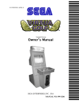
Owner’s Manual
SEGA AMUSEMENTS USA, INC.
MANUAL NO. 999-1930
GAME CODE:FZR
VISIT OUR WEBSITE!
BEFORE USING THE PRODUCT, BE SURE TO READ THE FOLLOWING:
To maintain the safety:
To ensure the safe usage of the product, be sure to read the following before using the product. The
following instructions are intended for the users, operators and the personnel in charge of the operation of the product. After carefully reading and sufficiently understanding the warning displays and
cautions, handle the product appropriately. Be sure to keep this manual nearby the product or elsewhere convenient for referring to it when necessary.
Herein, explanations which require special attention are enclosed with dual lines. Depending on the
potentially hazardous degrees, the terms of WARNING, CAUTION, etc. are used. Be sure to understand the contents of the displays before reading the text.
WARNING!
Indicates that mishandling the product by disregarding this warning
will cause a potentially hazardous
situation which can result in death
or serious injury.
CAUTION!
Indicates that mishandling the product
by disregarding this caution will cause
a slight hazardous situation which can
result in personal injury and or material
damage.
For the safe usage of the product, the following pictographs are used:
Indicates “HANDLE WITH CARE.” In order to protect the human body an equipment,
this display is attached to places where the Owner’s Manual and or Service Manual should
be referred to.
Perform work in accordance with the instructions herein stated.
Instructions for work are explained by paying attention to the aspect of accident prevention. Failing to
perform work as per the instructions can cause accidents. In the case where only those who have technical expertise should perform the work to avoid hazardous situation, the instructions herein state that the
serviceman should perform such work.
Be sure to turn off power before working on the machine.
To prevent electric shock, be sure to turn off power before starting the work in which the worker touches
the interior of the product. If the work is to be performed in the power-on status, the Instruction Manual
herein always states to that effect.
Be sure to ground the Earth Terminal (this, however, is not required in the case where a power cord
with earth is used).
This product is equipped with the Earth Terminal. When installing the product, Connect the Earth Terminal to the “accurately grounded indoor earth terminal” by using an earth wire. Unless the product is
grounded appropriately, the user can be subject to electric shock. After performing repair, etc. for the
Control equipment, ensure that the Earth Wire is firmly connected to the Control equipment.
Ensure that the Power Supply used is equipped with an Earth Leakage Breaker.
This product does not incorporate the Earth Leakage Breaker. Using a power supply which is not
equipped with the Earth Leakage Breaker can cause a fire when earth leakage occurs.
Be sure to use fuses which meet the specified rating. (only for the machines which use fuses).
Using fuses exceeding the specified rating can cause a fire and electric shock.
Specification changes (removal of equipment, conversion and addition) not designated by SEGA
are not allowed.
The parts of the product include warning labels for safety, covers for personal protection, etc. It is
very hazardous to operate the product by removing parts and or modifying the circuits. Should doors,
lids and protective parts be damaged or lost, refrain from operating the product, and contact where the
product was purchased from or the office herein stated. SEGA shall not be held responsible for any
accidents, compensation for damage to a third party, resulting from the specifications not designated by
SEGA.
Ensure that the product meets the requirements of appropriate Electrical Specifications.
Before installing the product, check for Electrical Specifications. SEGA products have a nameplate
on which Electrical Specifications are described. Ensure that the product is compatible with the power
supply voltage and frequency requirements of the location. Using any Electrical Specifications different
from the designated Specifications can cause a fire and electric shock.
Install and operate the product in places where appropriate lighting is available, allowing warning
labels to be clearly read.
To ensure safety for the customers, labels and printed instructions describing potentially hazardous situation are applied to places where accidents can be caused. Ensure that where the product is operated
has sufficient lighting allowing the warnings to be read. If any label is peeled off, apply it again immediately. Please place an order with where the product was purchased from or the office herein stated.
When handling the Monitor, be very careful. (Applies only to the product w/monitor.)
Some of the monitor (TV) parts are subject to high tension voltage. Even after running off power, some
portions are still subject to high tension voltage sometimes. Monitor repair and replacement should be
performed only be those technical personnel who have knowledge of electricity and technical expertise.
Be sure to adjust the monitor (projector) properly. (Applies only to the product w/monitor.)
Do not operate the product leaving on-screen flickering or blurring as it is. Using the product with the
monitor not properly adjusted may cause dizziness or a headache to an operator, a player, or the customers.
When transporting or reselling this product, be sure to attach this manual to the product.
In the case where commercially available monitors and printers are used in this product, only the contents relating to this product are explained herein. Some commercially available equipment has functions and reactions not stated in this manual. Read this manual together with the specific Instruction
Manual of such equipment.
• Descriptions herein contained may be subject to improvement changes without notice.
• The contents described herein are fully prepared with due care. However, should any question arise or
errors be found, please contact SEGA.
INSPECTIONS IMMEDIATELY AFTER TRANSPORTING THE PRODUCT TO THE LOCATION.
Normally, at the time of shipment, SEGA products are in a status allowing for usage immediately after
transporting to the location. Nevertheless, an irregular situation may occur during transportation. Before
turning on power, check the following points to ensure that the product has been transported in a satisfactory status.
Are there any dented portions or defects (cuts, etc.) on the external surfaces of the cabinet?
Are Casters and Adjusters, damaged?
Do the power supply voltage and frequency requirements meet with those of the location?
Are all wiring connectors correctly and securely connected? Unless connected in the correct direction,
connector connections can not be made accurately. Do not insert connectors forcibly.
Do power cords have cuts and dents?
Do the fuses used meet specified rating? Is the Circuit Protector in an energized status?
Are all accessories available?
Can all Doors and Lids be opened with the Accessory keys? Can Doors and Lids be firmly closed?
TABLE OF CONTENTS
BEFORE USING THE PRODUCT, BE SURE TO READ THE FOLLOWING:
TABLE OF CONTENTS
INTRODUCTION OF THE OWNER’S MANUAL
1. HANDLING PRECAUTIONS ..........................................................................................
2. PRECAUTIONS CONCERNING INSTALLATION LOCATION ...................................
3. PRECAUTIONS CONCERNING PRODUCT OPERATION ...........................................
4. NAMES OF PARTS ...........................................................................................................
5. ACCESSORIES .................................................................................................................
6. ASSEMBLY AND INSTALLATION .................................................................................
7. CARD READER/WRITER ................................................................................................
8. PRECAUTIONS WHEN MOVING THE MACHINE ......................................................
9. GAME DESCRIPTION ......................................................................................................
10. TEST AND DATA DISPLAY .............................................................................................
11. STEERING UNIT ................................................................................................................
12. CONTROL PANEL ..............................................................................................................
13. ACCELERATOR & BRAKE ...............................................................................................
14. COIN SELECTOR ...............................................................................................................
15. MONITOR ............................................................................................................................
16. REPLACING THE FLUORESCENT LAMP ......................................................................
17. PERIODIC INSPECTION TABLE ......................................................................................
18. TROUBLESHOOTING .......................................................................................................
19. GAME BOARD ...................................................................................................................
20. NETWORK PLAY ...............................................................................................................
21. DESIGN RELATED PARTS ...............................................................................................
22. PARTS LIST ........................................................................................................................
23. WIRE COLOR CODE TABLE ...........................................................................................
24. WIRING DIAGRAM ...........................................................................................................
2 - 3
4 - 5
6 - 11
12
13 - 14
15 - 33
34 - 38
39 - 40
41 - 51
52 - 87
88 - 98
99 - 103
104 - 105
106 - 107
108 - 110
111 - 112
113 - 114
115 - 126
127 - 138
139 - 144
145
146 - 163
164
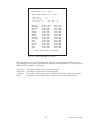
XXX
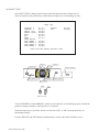
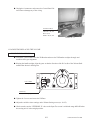
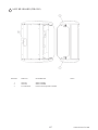
Installation Space
Height
Width
Length
Weight
Power, maximum current
MONITOR
SPECIFICATIONS
:
:
:
:
:
:
72 inches width X 90 inches deep
77 inches
39 inches
68.5 inches
580 lbs
600 W 5 A (AC 120V 60 Hz AREA)
: Sanwa #29E31S
Sega Part Number: 998-0162
Chassis Part Number: 998-0161
INTRODUCTION OF THE OWNERS MANUAL
This Owner's Manual is intended to provide detailed descriptions together with all the
necessary information covering the general operation of electronic assemblies, electromechanicals, servicing control, spare parts, etc. as regards the product,
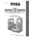
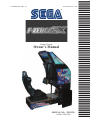
F-ZERO AX STANDARD TYPE.
This manual is intended for the owners, personnel and managers in charge of operation
of the product. Operate the product after carefully reading and sufficiently understanding the instructions. If the product fails to function satisfactorily, non-technical personnel
should under no circumstances touch the internal system. Please contact where the product was purchased from.
Use of this product is unlikely to cause physical injuries or damages to property. However,
where special attention is required this is indicated by a thick line, the word "IMPORTANT"
and its sign in this manual.
STOP
Indicates that mishandling the product by disregarding this display can cause the
product's intrinsic performance not to be obtained, resulting in malfunctioning.
IMPORTANT!
SEGA AMUSEMENTS USA, INC. / CUSTOMER SERVICE
45133 Industrial Drive, Fremont, California 94538, U.S.A.
Phone : (415) 701-6580
Fax : (415) 701-6594
DEFINITION OF LOCATION MAINTENANCE MAN AND SERVICEMAN
WARNING!
Non-technical personnel who do not have technical knowledge and expertise should
refrain from performing such work that this manual requires the location's maintenance man or a serviceman to carry out, or work which is not explained in this
manual. Failing to comply with this instruction can cause a severe accident such
as electric shock.
Ensure that parts replacement, servicing & inspections, and troubleshooting are performed by the
location's maintenance man or the serviceman. It is instructed herein that particularly hazardous work
should be performed by the serviceman who has technical expertise and knowledge.
The location's maintenance man and serviceman are herein defined as follows:
"Location's Maintenance Man" :
Those who have experience in the maintenance of amusement equipment and vending machines, etc.,
and also participate in the servicing and control of the equipment through such routine work as equipment assembly and installation, servicing and inspections, replacement of units and consumables, etc.
within the Amusement Facilities and or locations under the management of the Owner and Owner's
Operators of the product.
Activities of Location's Maintenance Man :
Assembly & installation, servicing & inspections, and replacement of units & consumables as regards
amusement equipment, vending machines, etc.
Serviceman :
Those who participate in the designing, manufacturing, inspections and maintenance service of the
equipment at an amusement equipment manufacturer.
Those who have technical expertise equivalent to that of technical high school graduates as regards
electricity, electronics and or mechanical engineering, and daily take part in the servicing & control
and repair of amusement equipment.
Serviceman's Activities :
Assembly & installation and repair & adjustments of electrical, electronic and mechanical parts of
amusement equipment and vending machines.
LISTED
UL
®
5K92
AMUSEMENT MACHINE
Notes:
440-W
S0179-E G
440-W
S0166EG
440-C
S0186EG
CONCERNING WARNING DISPLAYS
Electrical Specifications Display
440-W
S0002X
EG
440DS0013X
EG
CONCERNING THE STICKER DISPLAY
Serial No. Display
SEGA product has warning displays on Stickers,
Labels and or printed instructions adhered/attached
to or incorporated in the places where a potentially
hazardous situation can arise. The warning displays are
intended for accident prevention for the customers and
for avoiding hazardous situation relating to maintenance
and servicing work. There are some portions in the
Cabinet, which are subject to high tension voltage, etc.
where accidents can be caused merely by touching.
When performing the servicing work , be very careful
of the warning displays. Especially, any complex repair
and replacement work not mentioned herein, should
be performed by those technical personnel who have
knowledge of electricity and technical expertise.
For the prevention of accidents, caution any customer
whose act runs counter to the warnings, as to the effect
that he must stop the act.
SEGA product has Stickers describing the product
manufacture No. (Serial No.) and Electrical
Specifications. Also it has a Sticker describing where to
contact for repair and for purchasing parts.
When inquiring about or asking for repair, mention
the Serial No. and Name of Machine indicated on the
Sticker. The Serial No. indicates the product register.
Identical machines could have different parts depending
on the date of production. Also, improvements
and modifications might have been made after the
publication of this Manual. In order to meet the above
situations, mention the Serial No. when contacting the
applicable places.
1
www.seuservice.com
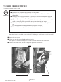
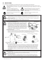
1. HANDLING PRECAUTIONS
When installing or inspecting the machine, be very careful of the following points and pay attention to
ensure that the player can enjoy the game safely.
Non-compliance with the following points or inappropriate handling running counter to the cautionary
matters herein stated can cause personal injury or damage to the machine.
WARNING!
Before performing work, be sure to turn power off. Performing the work without
turning power off can cause an electric shock or short circuit. In the case work
should be performed in the status of power on, this manual always states to that
effect.
To avoid electric shock or short circuit, do not plug in or unplug quickly.
To avoid electric shock, do not plug in or unplug with a wet hand.
Do not expose Power Cords and Earth Wires on the surface, (floor, passage, etc.).
If exposed, the Power Cords and Earth Wires are susceptible to damage. Damaged
cords and wires can cause electric shock or short circuit.
To avoid causing a fire or electric shock, do not put things on or damage Power
Cords.
When or after installing the product, do not unnecessarily pull the power cord. If
damaged, the power cord can cause a fire or electric shock.
In case the power cord is damaged, ask for replacement through where the product
was purchased from or the office herein stated. Using the cord as is damaged can
cause fire, electric shock or leakage.
Be sure to perform grounding appropriately. Inappropriate grounding can cause an
electric shock.
Be sure to use fuses meeting specified rating. Using fuses exceeding the specified
rating can cause a fire or electric shock.
Completely make connector connections for IC BD and others. Insufficient insertion
can cause an electric shock.
Specification changes, removal of equipment, conversion and/or addition, not
designated by SEGA are not permitted.
• Failure to observe this may cause a fire or an electric shock. Non-compliance with
this instruction can have a bad influence upon physical conditions of the players or
the lookers-on, or result in injury during play.
• SEGA shall not be held responsible for damage, compensation for damage to a third
party, caused by specification changes not designated by SEGA.
Be sure to perform periodic maintenance inspections herein stated.
www.seuservice.com
2
STOP
IMPORTANT!
For the IC board circuit inspections, only the logic tester is allowed. The use of a
multiple-purpose tester is not permitted, so be careful in this regard.
The Projector is employed for this machine. The Projector's screen is susceptible
to damage, therefore, be very careful when cleaning the screen. For details, refer to
PROJECTOR.
Static electricity from your body may damage some electronics devices on the IC
board. Before handling the IC board, touch a grounded metallic surface so that the
static electricity can be discharged.
Some parts are the ones designed and manufactured not specifically for this game
machine. The manufacturers may discontinue, or change the specifications of, such
general-purpose parts. If this is the case, Sega cannot repair or replace a failed game
machine whether or not a warranty period has expired.
3
www.seuservice.com
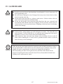
2. PRECAUTIONS REGARDING INSTALLATION LOCATION
WARNING!
This product is an indoor game machine. Do not install it outside. Even indoors, avoid
installing in places mentioned below so as not to cause a fire, electric shock, injury and
or malfunctioning.
Places subject to rain or water leakage, or places subject to high humidity in the
proximity of an indoor swimming pool and or shower, etc.
Places subject to direct sunlight, or places subject to high temperatures in the
proximity of heating units, etc.
Places filled with inflammable gas or vicinity of highly inflammable/volatile
chemicals or hazardous matter.
Dusty places.
Sloped surfaces.
Places subject to any type of violent impact.
Vicinity of anti-disaster facilities such as fire exits and fire extinguishers.
The operating (ambient) temperature range is from 5˚ to 30˚.
LIMITATIONS OF USAGE REQUIREMENTS
WARNING!
Be sure to check the Electrical Specifications.
Ensure that this product is compatible with the location's power supply, voltage and
frequency requirements.
A plate describing Electrical Specifications is attached to the product.
Non-compliance with the Electrical Specifications can cause a fire and electric
shock.
This product requires the Breaker and Earth Mechanisms as part of the location
facilities. Using them in a manner not independent can cause a fire and electric
shock.
Ensure that the indoor wiring for the power supply is rated at 7 A or higher (AC
single phase 100~120 V area), and 4 A or higher (AC 220~240 V area). Noncompliance with the Electrical Specifications can cause a fire and electric shock.
Be sure to independently use the power supply equipped with the Earth Leakage
Breaker. Using a power supply without the Earth Leakage Breaker can cause an
outbreak of fire when earth leakage occurs.
Putting many loads on one electrical outlet can cause generation of heat and a fire
resulting from overload.
When using an extension cord, ensure that the cord is rated at 7 A or higher (AC
100~120 V area) and 4 A or higher (AC 220~240 V area). Using a cord rated lower
than the specified rating can cause a fire and electric shock.
www.seuservice.com
4
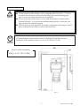
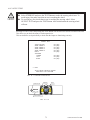
OPERATION AREA
WARNING!
STOP
IMPORTANT!
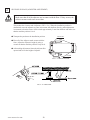
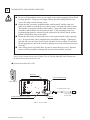
For the operation of this machine, secure a minimum area of 6 Ft (W) × 7.5 Ft (D).
In order to prevent injury resulting from the falling down accident during game
play, be sure to secure the minimum area for operation.
Be sure to provide sufficient space so as to allow this product's ventilation fan to
function efficiently. To avoid machine malfunctioning and a fire, do not place any
obstacles near the ventilation opening.
SEGA shall not be held responsible for damage, compensation for damage to a third
party, resulting from the failure to observe this instruction.
For transporting the machine into the location's building, the minimum necessary
dimensions of the opening (of doors, etc.) are 40 in (W) and 77 in (H).
Electric current consumption
MAX. 5 A (AC 120 V 60 Hz)
FIG. 2
5
www.seuservice.com
3. PRECAUTION REGARDING PRODUCT OPERATION
PRECAUTIONS TO BE HEEDED BEFORE STARTING THE OPERATION
To avoid injury and trouble, be sure to constantly give careful attention to the behavior and manner of the
visitors and players.
In order to avoid accidents, check the following before starting the operation:
WARNING!
To ensure maximum safety for the players and the customers, ensure that where
the product is operated has sufficient lighting to allow any warnings to be read.
Operation under insufficient lighting can cause bodily contact with each other, hitting
accident, and or trouble between customers.
Be sure to perform appropriate adjustment of the monitor (projector). For operation
of this machine, do not leave monitor's flickering or deviation as is. Failure to
observe this can have a bad influence upon the players' or the customers' physical
conditions.
It is suggested to ensure a space allowing the players who feel sick while playing the
game to take a rest.
Check if all of the adjusters are in contact with the surface. If they are not, the
Cabinet can move and cause an accident.
Ensure that all of the
SUPPORT BRACKET are in contact
with the floor.
Ensure that all of the
Adjusters are in contact
with the floor.
www.seuservice.com
6
WARNING!
CAUTION!
STOP
Do not put any heavy item on this product. Placing any heavy item on the product
can cause a falling down accident or parts damage.
Do not climb on the product. Climbing on the product can cause falling down
accidents. To check the top portion of the product, use a step.
To avoid electric shock, check to see if door & cover parts are damaged or omitted.
To avoid electric shock, short circuit and or parts damage, do not put the following
items on or in the periphery of the product.
Flower vases, flowerpots, cups, water tanks, cosmetics, and receptacles/containers/
vessels containing chemicals and water.
To avoid injury, be sure to provide sufficient space by considering the potentially
crowded situation at the installation location. Insufficient installation space can
cause making bodily contact with each other, hitting accidents, and or trouble
between customers.
Check the control devices to make sure that there are no scratches or cracks on parts
touched by players, as such defects can cause injury to hands and fingers.
This product features a license card slot and a memory card slot. Check to make sure that
these parts have not been tampered with (e.g. by inserting foreign objects.)
IMPORTANT!
7
www.seuservice.com
DURING OPERATION(PATRON CONDUCT)
To avoid injury and trouble, be sure to constantly give careful attention to the behavior and
manner of the visitors and players.
WARNING!
To avoid injury and accidents, those who fall under the following categories are not
allowed to play the game.
• Those who need assistance such as the use of an apparatus when walking.
• Those who have high blood pressure or a heart problem.
• Those who have experienced muscle convulsion or loss of consciousness when playing
video game, etc.
• Those who have a trouble in the neck and or spinal cord.
• Intoxicated persons.
• Pregnant women or those who are in the likelihood of pregnancy.
• Persons susceptible to motion sickness.
• Persons whose act runs counter to the product's warning displays.
A player who has never been adversely affected by light stimulus might experience
dizziness or headache depending on his physical condition when playing the game.
Especially, small children can be subject to those conditions. Caution guardians of
small children to keep watch on their children during play.
Instruct those who feel sick during play to have a medical examination.
To avoid injury resulting from falling down and electric shock due to spilled drinks,
instruct the player not to place heavy items or drinks on the product.
To avoid electric shock and short circuit, do not allow patrons to put hands and
fingers or extraneous matter in the openings of the product or small openings in or
around the doors.
To avoid falling down and injury resulting from falling down, immediately stop the
patron's leaning against or climbing on the product, etc.
To avoid electric shock and short circuit, do not allow the patrons to unplug the
power plug without a justifiable reason.
This product is intended for 1 Player only. Playing the game by 2 or more Players
riding on the seat together can cause falling down and collision accidents by striking
head, hand, or elbow.
Persons other than the player should not be allowed to touch the controls during play.
They may brush against or collide with the controls or the player, possibly resulting
in accidents.
www.seuservice.com
8
WARNING!
CAUTION!
Caution the player so as not to
hold a child in her/his lap to
play. Failure to observe this
may cause the child to be
caught between the Control
Panel and the player and fall
down.
Immediately stop such violent acts as hitting and kicking the product. Such violent
acts can cause parts damage or falling down, resulting in injury due to fragments and
falling down.
Instruct the Player to adjust the seat before playing the game. Playing the game in a
forcible posture can cause a contingent accident.
9
www.seuservice.com
OPERATING THE CARD SYSTEM
STOP
IMPORTANT!
When an unjust act is performed, no written data is backed up mechanically.
The following acts may be judged to be unjust acts.
Since it also becomes a defect of operation and the cause of parts damage, caution
the player not to perform the following acts.
•Use of cards bent or deformed
•Use of cards adhered seals or extraneous matter on
•Use of a card mixed two sheets
•Use of cards other than dedicated cards
•When a card is extracted quickly
Since the order in which cards are dispensed is random, note that there may be cases
in which the same card comes out several times in a row or a certain card fails to
come out at all.
If the card reader/writer has not been set as being unused, you will be unable to select any game mode
with use of cards while the game will be in progress.
Thus, for the card reader/writer, deal with the player, paying attention to the following points:
Even if the player request the system for use of cards when you have set the machine so that the card
reader/writer is not used, the request is rejected because of the nature of the system.
www.seuservice.com
10
USING MEMORY CARDS
Players who use memory cards should be advised of the following
precautions. Data that is damaged or lost cannot be recovered.
- Before inserting a memory card, check to make sure there are no
problems with the slot.
- When using a memory card and a license card at the same time,
insert the memory card first. Player data will not be used in the
game if the cards are inserted in the wrong order.
F-ze
ro
LIC
EN
CE
CA
RD
- Be sure to use a memory card containing "F-ZERO GX" game data.
- Never attempt to remove/insert a card during play. Doing so may damage the data.
- Do not use memory cards other than authorized Nintendo products or official licensed products.
11
www.seuservice.com
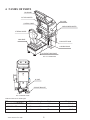
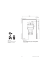
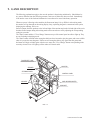
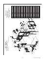
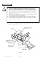
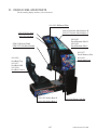
4. NAMES OF PARTS
BILLBOARD
29TYPE MONITER
POP CARD
CONTROL PANEL
CARD READER/WRITER
STEERIN G WHEEL
MAIN BASE
COIN CHUTE DOOR
CASHBOX DOOR
ACCELERATOR & BRAKE
FIG. 4 a OVERVIEW
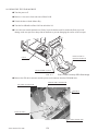
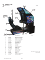
AC UNIT
SUPPORT BRACKET
FIG. 4 b REAR VIEW
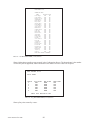
TABLE 4 Dimensions and Weights
CABINET
BILLBOARD
When assembled
www.seuservice.com
Width × Length ×
39 in × 68.5 in ×
32 in ×
26 in ×
39 in × 68.5 in ×
12
Height
60 in
17 in
77 in
Weight
550 lbs
28.6 lbs
580 lbs
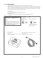
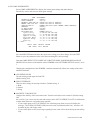
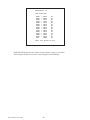
5. ACCESSORIES
When transporting the machine, make sure that the following parts are supplied.
Magnetic cards for the recording of play results, and cleaning kits for cleaning the head of the card reader/
writer are sold separately. Subsequent purchases of these items can be made by contacting the office listed
on this Owner's Manual or the dealer from whom the product was originally purchased. Be sure to provide
the part number(s), name(s), and required number of items.
Cleaning Kit
601-11050 CLEANING CARD: Package of 30 sheets
Magnetic Cards
601-11334-01 CARD PACKAGE FZR ENG: Package of 200 Magnetic Cards
TABLE 5 a ACCESSORIES
DESCRIPTION
Part No. (Qty.)
Notes
OWNER'S MANUAL
999-1930
Figures
Parts not labeled with part numbers are as yet
unregistered or cannot be registered. Be sure to
handle all parts with care, as some parts are not
available for purchase separately.
CLEANING CARD
601-11050 (1)
For the periodic maintenance. See Sections 7 and 10.
(30 sheets of Cleaning Card)
KEY MASTER
220-5576 (2)
For opening/closing
the doors
KEY
(2)
For the CASHBOX DOOR
The Keys are inside the Coin
Chute Door at the time of shipment from the factory.
ASSY FIBER CABLE (NETWORK CABLE) 5 m
600-7269-0500 (1)
Used for the Network Play. See Section 20.
13
www.seuservice.com
GD SOFT KIT FZR
610-0650-0004 (1) <OTHERS>
GD-ROM software.
See 3 of Section 6.
CUSHION SPONGE
601-11137 (1)
GD-ROM Disc Protector
GD-ROM DISC
DISC CASE
253-5507
The following Table 5b lists the parts that are separately marketed but are necessary when booting this
product's software. When having unpacked the shipping crate, make sure that all the parts in this Table 5b
are in the crate. If not so, contact where you have obtained the product.
TABLE 5 b (XKT-0833 : GD-ROM DRIVE KIT)
GD-ROM DRIVE CARTON BOX (1)
Used for transporting the GD-ROM DRIVE.
See Section 19.
123
GD-ROM DRIVE
610-0617
(1)
610-0617-01
Device that loads the software in a GD-ROM disc.
see 3 of Section 6.
This carton box is a standard accessory of
the GD-ROM drive. If you want to obtain the
carton box itself separately, specify the part
number 601-11031.
www.seuservice.com
14
6. ASSEMBLY AND INSTALLATION
WARNING!
CAUTION!
Perform assembly work by following the procedure herein stated. Failing to comply
with the instructions can cause electric shock hazard.
Perform assembling as per this manual. Since this is a complex machine, erroneous
assembling can cause an electric shock, machine damage and or not functioning as
per specified performance.
When assembling, be sure to use plural persons. Depending on the assembly work,
there are some cases in which working by one person alone can cause personal
injury or parts damage.
Ensure that connectors are accurately connected. Incomplete connections can cause
electric shock hazard.
Be careful not to damage the wires. Damaged wires may cause electric shock or
short circuit or present a fire risk.
This work should be performed by the site maintenance individual or other skilled
professional. Performing work by non-technical personnel can cause a severe
accident such as electric shock. Failing to comply with this instruction can cause a
severe accident such as electric shock to the player during operation.
Provide sufficient space so that assembling can be performed. Performing work in
places with narrow space or low ceiling may cause an accident and assembly work
to be difficult.
To perform work safely and avoid serious accident such as the cabinet's falling
down, do not perform work in places where step-like grade differences, a ditch, or
slope exist.
Do not leave power cords, grounding wires, or network cables exposed in areas of
heavy foot traffic. Doing so may cause them to become damaged, possibly resulting
in electric shock and/or short circuits. When laying wiring across the floor, always
use safety covers to protect the wires. (Wiring diameter: power cable - approx. 8mm;
network cable - approx. 5mm)
Handle molded parts with care. Undue weight or pressure may cause them to break
and the broken pieces may cause injury.
To perform work safely and securely, be sure to prepare a step which is in a secure
and stable condition. Performing work without using the step can cause violent
falling down accidents.
Make sure that the GD cable connector is inserted parallel to the plug. Improper
insertion may cause damage to the connector and present a fire risk.
15
www.seuservice.com
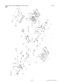
When carrying out the assembling and installation, follow the following 6-item sequence.
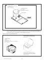
1
INSTALLING THE BILLBOARD AND THE POP CARD
2
SECURING IN PLACE(ADJUSTER ADJUSTMENT)
3
INSTALLING THE GD-ROM DRIVE(SETTING THE GD-ROM DISC)
4
POWER SUPPLY, AND EARTH CONNECTION
5
TURNING THE POWER ON
6
ASSEMBLY CHECK
The master key (accessories) in addition to the tools such as a Phillips type screwdriver, wrench,
socket wrench and Ratchet Handle are required for the assembly work.
24mm
WRENCH (for M16 hexagon-head bolt)
KEY MASTER
Phillips type screwdriver
www.seuservice.com
SOCKET WRENCH,(for M8 hexagon-head bolt)
RATCHET HANDLE
16
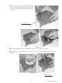
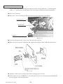
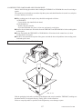
1
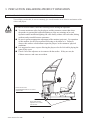
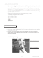
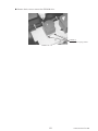
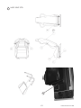
INSTALLING THE BILLBOARD AND POP CARD
Install the billboard on the
cabinet. This operation should be
performed by at least 2 people
working together.
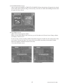
PHOTO 6. 1 a
FIG. 6. 1 a
For performing work, prepare a step.
Secure the billboard with 4 hexagonal
bolts.
HEXAGONAL BOLT(4), black
M8×20, w/spring washer, flat washer used
PHOTO 6. 1 b
17
www.seuservice.com
Remove the 2 truss screws from the connector lid and then remove the lid.
TRUSS SCREW (2), black
M4×8
CONNECTOR LID
PHOTO 6. 1 c
Plug in the connectors.
Connect
PHOTO 6. 1 d
Re-install the 2 truss screws on the connector lid.
www.seuservice.com
18
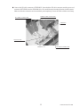
Attach the billboard plate to the billboard.
Secure each side of the billboard with 2 truss
screws and a plate sash.
TRUSS SCREW (2 ea.) black
M5×12
BILLBOARD PLATE
PLATE SASH
PHOTO 6. 1 e
Assembling the POP Card as shown in the figure and attach it to the top of the Card Reader/Writer.
POP CARD
CARD READER/WRITER
FIG. 6. 1
19
www.seuservice.com
2
WARNING!
SECURING IN PLACE (ADJUSTER ADJUSTMENT)
Make sure that all of the adjusters are in contact with the floor. If they are not, the
cabinet can move and cause an accident.
This product has 4 casters and 4 Adjusters. (FIG. 6. 2 a) When the installation position is
determined, cause the adjusters to come into contact with the floor directly, make adjustments
in a manner so that the casters will be raised approximately 5 mm from the floor and make sure
that the machine position is level.
Transport the product to the installation position.
ADJUSTER
Have all of the Adjusters make contact with the
floor. Adjust the Adjuster's height by using a
wrench so that the machine position is kept level.
After making adjustment, fasten the Adjuster Nut
upward and secure the height of Adjuster.
CASTER
FIG. 6. 2 a BOTTOM VIEW
FIG. 6. 2 b ADJUSTER
www.seuservice.com
20
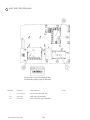
FIG. 6. 2 e
Provide ventilation space for the ventilation opening.
Allow more than 70 cm (approx. 28 in) of space for
customer traffic.
FIG. 6. 2 d
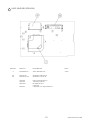
Refer to this Fig. (Scale:1/100)
for the layout of the place of
installation.
21
www.seuservice.com
3
INSTALLING THE GD-ROM DRIVE (SETTING THE GD-ROM DISC)
STOP
IMPORTANT!
Carefully handle the GD-ROM drive so as not to contaminate the disc and the
readout lens with stains and dust particles.
Do not continue to use the scratched GD-ROM disc. The scratched GD-ROM disc
may cause the system to malfunction.
Set the GD-ROM disc onto the GD-ROM drive with its labeled side facing upward.
The key chip is a precision device. Handle it carefully and avoid exposure to heat,
shock and static electricity, as these may cause damage to the device.
The key chip is contained in the GD-ROM disc case. Always use them as a set.
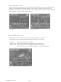
Unpack the shipping crate, and take out the GD-ROM drive, GD-ROM drive bracket, and GD-ROM
disc.
GD DRIVE BRACKET
GD-ROM DRIVE
PHOTO 6. 3 a
Use the 4 tapping screws to fix the GD-ROM drive bracket onto the GD-ROM drive. Be careful about a
fixing direction.
TAPPING SCREW (4)
M4×8
GD DRIVE BRACKET
FIG. 6. 3 b
GD-ROM DRIVE
CAUTION for U. S. A., Europe, and Australia:
Attach the 2 caution stickers for a laser ray onto
the GD-ROM drive.
FIG. 6. 3 a
www.seuservice.com
22
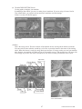
Remove the 1 truss screw that fixes the GD-ROM
drive lid (DISC LID). And turn clockwise the lid
to remove. Keep the screw to replace the disc lid
below.
TRUSS SCREW (1)
M3×8
PHOTO 6. 3 b
Set the GD-ROM disc onto the GD-ROM drive with its labeled side facing upward.
Return the lid to its original place, and fix it with 1 truss screw. Be careful not to fasten the screw too
tightly.
PHOTO 6. 3 c
TRUSS SCREW (1)
M3×8
23
www.seuservice.com
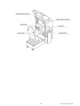
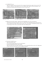
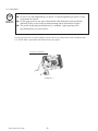
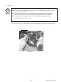
Undo the lock on the side of the unit base and remove the Truss screws.
Turn the lock handle to open the lock, and lower the seat towards the backrest. Slowly lower the backrest
until it touches the floor to prevent damage to the seat components. Put a drop cloth on the floor to
prevent damaging the surface of the seat components.
LOCK HANDLE
DROP CLOTH TO PREVENT DAMAGE
TO SURFACE OF PARTS
Unlock.
TRUSS SCREW (2), black
M5×12
FIG. 6. 3 b
Attach the GD-ROM drive with 3 screws.
SCREW (3)
M4×16,
w/flat & spring washers
PHOTO 6. 3 d
www.seuservice.com
24
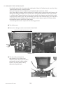
Connect the GD cable connector to TRIFORCE. Insert both the GD cable connector and the power cord
connector (JST NH6P) into the GD-ROM drive. Be careful about an inserting direction in this instance.
Make sure that the connectors are inserted firmly and completely. Secure the cable with the cord clamp.
GD CABLE CONNECTOR
POWER CORD CONNECTOR
JST NH6P
TRIFORCE
Secure the cable.
PHOTO 6. 3 e
25
GD CABLE CONNECTOR
www.seuservice.com
4
POWER SUPPLY, AND EARTH CONNECTION
WARNING!
Be sure to independently use the power supply socket outlet equipped with an Earth
Leakage Breaker. Using a power supply without an Earth Leakage Breaker can
cause a fire when electric leakage occurs.
Ensure that the "accurately grounded indoor earth terminal" and the earth wire
cable are available (except in the case where a power cord plug with earth is used).
This product is equipped with the earth terminal. Connect the earth terminal and
the indoor earth terminal with the prepared cable. If the grounding work is not
performed appropriately, customers can be subjected to an electric shock, and the
product's functioning may not be stable.
Ensure that the power cord and earth wire are not exposed on the surface (passage,
etc.). If exposed, they can be caught and are susceptible to damage. If damaged,
the cord and wire can cause electric shock and short circuit accidents. Ensure that
the wiring position is not in the customer's passage way or the wiring has protective
covering.
After wiring power cord on the floor, be sure to protect the power cord. Exposed
power cord is susceptible to damage and causes an electric shock accident.
The AC Unit is located on one side of Cabinet. The AC Unit has Main SW, Earth Terminal and
the Inlet which connects the Power Cord.
Ensure that the Main SW is OFF.
MAIN SW
CIRCUIT PROTECTOR
Main SW off
AC Cable (Power Cord)
INLET
EARTH TERMINAL <For Taiwan>
Connect with the indoor earth terminal.
FIG. 6. 4 a AC UNIT
www.seuservice.com
26
To the Power Supply
Socket outlet
Connect one end of the earth wire to
the AC Unit earth terminal, and the
other end to the indoor earth terminal.
The AC Unit earth terminal has a
Bolt and Nut combination. Take off
the Nut, pass the end of earth wire
through the Bolt, and fasten the Nut.
<For Taiwan>
Connect the Earth Wire
to the Earth Terminal.
*Note that the Earth Wire is
incorporated in the Power Cord for
the Areas of AC 120 V (USA) and
AC 220~240 V, and therefore, this
procedure is not necessary.
FIG. 6. 4 b *Earth Wire Connection
Firmly insert the power plug into the
socket outlet.
Insert the opposite side of Power
Cord plug to the AC Unit's connector
("INLET").
Perform wiring for the Power Cord
and Earth Wire. Install protective
covering for the Power Cord and
Earth Wire.
Wiring Cover
FIG. 6. 4 c Connecting Power Cord and Earth Wire
In case the Power Plug is apt to come out of place, secure the
Power Cord to the periphery of the AC Unit with the Cord
Clamp (an accessory).
HOW TO USE THE CORD CLAMP
27
www.seuservice.com
5
CAUTION!
TURNING THE POWER ON
Do not touch the machine until it has competed the initialization process and the
advertising screen has appeared. Doing so may cause the person touching the machine to
be struck by the seat. It may also prevent the machine from initializing properly. Failure
to initialize properly can lead to control malfunction and other problems.
Turn the main switch on the AC unit ON to turn on the power. The fluorescent lamp inside the billboard
will light up when the power is turned on.
After displaying the system startup screen, the monitor will indicate that the card reader/writer and motor,
in that order, are being tested.
Next, the initialization screen will be displayed, and the initialization process will begin. Initialization
consists of the following steps, with each part moving and coming to rest in the preset position and
direction automatically.
1) The steering wheel rotates left and right.
2) The steering wheel comes to rest in a 12 o'clock position.
When the initialization process is complete, the machine will go into Advertising mode. The monitor will
display the demo screen, and the speakers to the left and right of the monitor and on the left and right of
the seat's headrest will begin sound output. If the "no sound during Advertising mode" option is selected,
sound output will be turned off.
When a sufficient number of credits have been inserted, the "Start" button on top of the control panel will
flash. After the race begins, the "View Change" button for the currently selected mode will light up. The
buttons will not be lit up during Advertising mode when no credits have been inserted.
After displaying the initialization screen, if the machine is set for network play, the monitor will indicate
that the network is being tested.
If there are no problems with the network play connection and settings, the machine will enter
Advertising mode.
If there is a problem with game board system, an error message will be displayed on the screen. If there
is a problem with steering unit response, an error message will be displayed. Refer to the on-screen error
message to locate and resolve the problem.
If, after the initialization process is complete, the seat comes to rest at an angle or the steering unit comes
to rest in a position other than straight, turn the power off and back on and have the machine go through
initialization again.
If the steering unit continues to come to rest at an angle after going through initialization again, there is
likely a problem such as bad VR settings or a glitch in the initialization process. Adjust the VR settings.
(See Sections 10, 11 and 12.)
If there are any defects or abnormalities in the network play connection or settings, the machine will
continue to display the network test screen. Check the network play cable connection and settings.
The machine will save the number of credits inserted and rankings data even when the power is turned
off. Fractions of credits (i.e. any coins inserted that do not add up to a full credit) and bonus adder count
data will not be saved.
www.seuservice.com
28
FIG. 6. 5
29
www.seuservice.com
6
ASSEMBLY CHECK
In the TEST MODE, ascertain that the assembly has been made correctly and IC BD. is satisfactory
(refer to Section 10).
In the test mode, perform the following test:
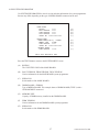
(1)MEMORY TEST
Selecting RAM TEST or MEDIA BOARD
TEST from the menu screen in System Test
mode will cause the machine to automatically
perform a test of the memory on the game
boards. If "GOOD" is displayed next to the
number of each memory segment, the game
boards are working properly.
Select SYSTEM INFORMATION to display
information on the main game board and the
media board. If the information is displayed
correctly, this indicates that the game boards are
functioning properly.
��������RAM�TEST
����AUX�MEMORY����GOOD
PRESS�TEST�BUTTON�TO�EXIT
���MEDIA�BOARD�TEST��1/2
���MEDIA�BOARD�TEST��2/2
����DOMM�BOARD(TYPE�3)
����VERSION��****
����STATUS���GOOD
����CHECKING�100%
��NETWORK�BOARD
��VERSION��****
��STATUS���GOOD
��CHECKING�100%
����DIMM�TEST
����DIMM0�����-�GOOD
����DIMM1�����-�NONE
����GD-ROM����-�GOOD
��NETWORK�BOARD�TEST
��RAM�CHECK�_�GOOD
����--��COMPLETED��--
PRESS�TEST�BUTTON�TO�EXIT
PRESS�TEST�BUTTON�TO�EXIT
����SYSTEM�INFORMATION
��MAIN�BOARD
����REGION���������****
����BOOT�VERSION���****
����FIRM�VERSION���****
����FPGA�VERSION���****
����SERIAL�NO.�***************
��MEDIA�BOARD
����DIMM�BOARD(TYPE�3)+�GDROM
����MEMORY�SIZE����512MB
����FIRM�VERSION���****
����SERIAL�NO.�***************
����NETWORK�BOARD
����FIRM�VERSION���*****
PRESS�TEST�BUTTON�TO�EXIT
www.seuservice.com
30
(2)INPUT TEST
Select INPUT TEST from the menu screen in either System Test mode or Game Test mode to
bring up a test screen for the input devices.
Test the input on each device. If "ON" is displayed next to each device as it is tested and the
numbers change smoothly in accordance with the input, the input devices and their wiring
connections are working properly.
��������������JVS�TEST
�������������INPUT�TEST
����NODE�������1/1
������SYSTEM�����00
������PLAYER�1���0000
������PLAYER�2���0000
������COIN�1�����0000
������COIN�2�����0000
������ANALOG�1���0000
������ANALOG�2���0000
������ANALOG�3���0000
������ANALOG�4���0000
������ANALOG�5���0000
������ANALOG�6���0000
������ANALOG�7���0000
������ANALOG�8���0000
PRESS�TEST�AND�SERVICE�BUTTON�TO�EXIT
�����������������������INPUT�TEST
STEERING��X�����0(~FF)�������SERVICE��������OFF(ON)
STEERING��Y�����0(~FF)�������TEST�����������OFF(ON)
PADDLE��LEFT����OFF(ON)
PADDLE��RIGHT���OFF(ON)
BOOST�����������OFF(ON)
GAS�������������0(~FF)
BRAKE�����������0(~FF)
START�BUTTON
VIEW�CHANGE�1���OFF(ON)
VIEW�CHANGE�2���OFF(ON)
VIEW�CHANGE�3���OFF(ON)
VIEW�CHANGE�4���OFF(ON)
�������PRESS�TEST�AND�SERVICE�BUTTON�TO�EXIT
31
www.seuservice.com
(3)SOUND TEST
In the system test mode, selecting SOUND
TEST causes the screen (on which sound
related BD and wiring connections are
tested) to be displayed.
Check if the sound is satisfactorily emitted
from each speaker and the sound volume is
appropriate.
��������SOUND�TEST
��OUTPUT�TYPE�������STEREO
��RIGHT�SPEAKER�����OFF
��LEFT��SPEAKER�����OFF
→EXIT
SELECT�WITH�SERVICE�BUTTON
��AND�PRESS�TEST�BUTTON
(4)C.R.T. TEST
In the system test mode menu, selecting
C.R.T. TEST allows the screen (on which the
monitor is tested) to be displayed. Although
the monitor adjustments have been made
at the time of shipment from the factory,
color deviation, etc., may occur due to the
effect caused by geomagnetism, the location
building's steel frames and other game
machines in the periphery. By watching the
system test mode screen, make judgment as
to whether an adjustment is needed. If it is
necessary, adjust the monitor by referring to
Chapter 15.
�����������������C.R.T.�TEST�1/2
���������������������EDIT
�����1�������������→NEXT���������������32
RED
GREEN
BLUE
WHITE
����������SELECT�WITH�SERVICE�BUTTON
������������AND�PRESS�TEST�BUTTON
C.R.T.�TEST�2/2
PRESS�TEST�BUTTON�TO�EXIT
www.seuservice.com
32
(5)OUTPUT TEST
�����������OUTPUT�TEST�
Select OUTPUT TEST from the menu
screen in Game Test mode to bring up a test
screen for the output devices (lamps, etc.)
If each output device activates correctly, the
output devices and their wiring connections
are working properly.
���START�BUTTON������������OFF(ON)
���VIEW�CHANGE�1�����������OFF(ON)
���VIEW�CHANGE�2�����������OFF(ON)
���VIEW�CHANGE�3�����������OFF(ON)
���VIEW�CHANGE�4�����������OFF(ON)
���BOOST�������������������OFF(ON)
���STEERING
�����CENTER����������������OFF(ON)
�����LEFT������������������OFF(ON)
�����RIGHT�����������������OFF(ON)
->�EXIT�
���SELECT�WITH�SERVICE�BUTTON
�����AND�PRESS�TEST�BUTTON
Perform the above inspections also at the time of monthly inspection.
33
www.seuservice.com
7. CARD READER/WRITER
7-1 SETTING DEDICATED CARDS
STOP
IMPORTANT!
Be sure to use dedicated cards available for this product.
Use of ones other than such dedicated cards may cause a malfunction or failure of
the machine.
Be sure to set the specified number of card in the specified orientation by using the
specified procedure. Wrong setting of the cards may cause the machine to fail.
This machine allows you to set up to 100 cards at a time. You must not set over 101
cards at a time. If you do so, a trouble such as card jamming may occur.
Set virgin cards taken out from a container that was unpacked immediately before
use.
Use of any deformed or deteriorated card may cause a trouble.
Do not include a corrugated, bent, or used card in the card deck.
When the unit is out of cards, a message will be displayed at the center of the screen. Follow the
instructions below to restock the system with cards. Cards may be stocked when the unit is on or off.
Remove the truss screw.
Unlock and open the cover to find the card reader/writer.
The dispenser on which you should place the cards is located at the rear of the reader/writer.
From the card reader/writer, take out the dispenser upward in a straight line.
Unlock.
DISPENSER
TRUSS SCREW(1), black
M4×8
www.seuservice.com
PHOTO 7. 1
34
Remove the cover from the back of the dispenser.
Be careful of instructions
of the sticker.
Dedicated
Cards
Remove the dispenser's cover.
Be sure to set the cards orientation.
Close the cover, and reinstall
the dispenser.
FIG. 7. 1 a
Place the cards into the dispenser according to the instructions on the sticker annexed to the dispenser.
Refer to the diagram shown on the sticker attached to the Dispenser and insert the cards into the
Dispenser. Be careful not to insert the cards in the wrong direction or with the wrong side facing up.
The Dispenser can only hold 100 cards. Do not attempt to insert more than 100 cards. Too many cards
may cause the Dispenser to jam or result in other problems.
Insert magnetic cards into the Dispenser in complete packs of 100 or after carefully counting the number
of cards (not to exceed 100).
FIG. 7. 1 b
Reinstall the cover to the dispenser.
Insert the dispenser into the card reader/writer. The dispenser can be inserted only in the predetermined
orientation.
Close and lock the cover.
Secure with the truss screw
35
www.seuservice.com
7-2 HEAD CLEANING
•
•
The unit enters Head Cleaning Mode when any of the following conditions are met:
At power-up if the Card Reader/Writer has operated 150 times or more
At boot time after performing Backup Data Clear
Once the unit enters Head Cleaning Mode, follow the on-screen instructions and
perform Head Cleaning. The unit will not exit Cleaning Mode (i.e. games may not be
played) until head cleaning is complete.
Always use the designated Cleaning Card. Using anything other than the designated
card or carrying out any other procedure other than the one outlined in the manual
may cause faulty printing, faulty operation and/or unit failure.
Cleaning Cards may only be used once. Dispose of them after use.
Cleaning Cards should be used immediately after removal from the package.
Cleaning Cards will not clean effectively if dried out.
Perform head cleaning only when there are cards in the Card Reader/Writer
Dispenser. If the Dispenser is empty, the part that secures the cards inside the
Dispenser may touch the rotating part of the Card Reader/Writer and cause noise.
Always remember to remove the Cleaning Card after completing head cleaning.
After head cleaning, wait for the "SEGA LOGO" to be displayed at least twice
before resuming gameplay.
This machine records the number of times the Card Reader/Writer is used.
The Card Reader/Writer writes data to and reads data from cards. Each write and read is counted, so the
Card Reader/Writer usage count will not be the same as the number of times the game is played.
Once head cleaning of the Card Reader/Writer is complete, the unit will exit this mode.
Follow the on-screen instructions to carry out cleaning.
CLEANING CARD
Insert the CLEANING CARD.
Insert the Cleaning Card into the card slot.
(NO MESSAGE)
The unit is undergoing cleaning. Wait for cleaning to be completed.
Retrieve the CLEANING CARD.
PHOTO 7. 2
Do not forget to remove the Cleaning Card.
The unit exits to normal mode after cleaning is complete.
Wait for the "SEGA LOGO" to be displayed at least twice before
resuming gameplay after cleaning.
The Card Reader/Writer usage count described above is reset when cleaning is performed.
Manual head cleaning may also be performed from Test Mode. Refer to Test Mode <10-3F> for more
details.
www.seuservice.com
36
7-3 CLEARING CARD JAMS
CAUTION!
When attempting to perform this operation without powering down so that gameplay can
be restored, exercise extreme caution. Machine parts may move unexpectedly when the
power is ON. This may result in fingers being caught or severed and other injuries.
Verify the Stay Lock on the top cover before attempting this procedure. If the top cover
closes during the procedure, it may result in serious injury.
If a trouble such as card jamming occurs on the card reader/writer, you are notified of the trouble on the
screen. You cannot proceed to a play unless you resolve the trouble at this time. First identify the trouble
before you begin to take action.
An error message is displayed at the top of the screen when cards become jammed.
When not discharging a card, follow the instructions below to remove the card. Removing the card may
force the game to shut down. If the game shuts down, existing customer game data will not be saved.
Remove the truss screw.
Unlock and open the cover.
Unlock.
TRUSS SCREW(1), black
M4×8
PHOTO 7. 3 a
37
www.seuservice.com
Unlock the hatch by drawing the green shaft attached to the top cover on the card reader/writer. While
drawing the shaft, open the cover up.
Remove the card jammed in the card reader/writer.
Remove the card jammed.
PHOTO 7. 3 b
While drawing the shaft, close the cover. With the top cover closed, release the green shaft. Check that
the top cover has been locked securely.
Close and lock the cover.
Secure with the truss screw.
www.seuservice.com
38
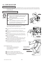
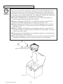
8. PRECAUTIONS WHEN MOVING THE MACHINE
WARNING!
CAUTION!
When moving the machine, be sure to unplug the power plug. Moving the machine
with the plug as is inserted can damage the power cord and cause fire and electric
shock hazards.
When moving the machine on the floor, retract the Adjusters and ensure that Casters
make contact with the floor. During transportation, pay careful attention so that
Casters do not tread power cords and earth wires. Damaging the power cords can
cause electric shock and short circuit hazards.
Do not push the cabinet from the left/right when attempting to move the unit.
Pushing from the sides may cause the unit to tip and result in injury and damage to
parts.
Do not push on any parts made of glass (e.g. CRT screen) or plastic, as these parts may
break and result in bodily injury.
Do not push the
cabinet from the
left/right direction.
FIG. 8 a
39
www.seuservice.com
In locations with low ceilings,
remove the Billboard before
moving the machine.
Place the machine on casters.
FIG. 8 b
www.seuservice.com
40
Remove the Support Brackets
from both sides.
9. GAME DESCRIPTION
The following explanations apply to the case the product is functioning satisfactorily. Should there be
any moves different from the following contents, some sort of faults may have occurred. Immediately
look into the cause of the fault and eliminate the cause thereof to ensure satisfactory operation.
Whenever power is flowing to the machine, the fluorescent lamp is lit up. While in Advertising mode,
the monitor will go through an advertising display loop, explaining the game's content and card system,
displaying the rankings, and so on.
Sound is output from the speakers to the left and right of the monitor and on the left and right of the seat's
headrest. Sound output during Advertising mode can be turned on or off by adjusting the corresponding
setting in test mode.
The "Start" button and the 4 "View Change" buttons on top of the control panel are able to light up. They
are not lit during Advertising mode.
The "Start" button will blink when enough credits have been inserted to play the game, and cease to blink
when it is pressed to start the game. If there are still enough credits to play again after the game ends,
the button will begin to blink again. After the race starts, the "View Change" button corresponding to the
currently selected view will light up; all the others will remain unlit.
FLUORESECT LAMP
MONITOR
SPEAKER
STEERING WHEEL
CONTROL PANEL
CARD READER/WRITER
SPEAKER
COIN INLET
FIG. 9 a
41
www.seuservice.com
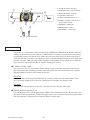
②
①
Left/Right
(1) START BUTTON: start game
③
Forward/Backward
④
(2) STEERING UNIT: control direction
(3) BOOST BUTTON: accelerate
(4) LICENSE CARD SLOT
(5) VIEW CHANGE BUTTON (1 - 4)
⑤
⑦
⑥
⑧
(6) PADDLE LEVER: control center of
gravity (while driving)
(7) MEMORY CARD SLOT
(8) BRAKE PEDAL: brake
⑨
(9) GAS PEDAL: control speed
FIG. 9 b CONTROL PANEL
Game Outline
This product is a racing game. It has two modes, RACE MODE and TIME ATTACK MODE. When the
cabinets are connected (up to four cabinets), VERSUS PLAY is available. The game features six courses
from which the players can choose freely. Each course has a time limit, and if you don't reach the goal
within the time limit, your time is up and the race will end. Passing through checkpoints and control lines
increases your time. Each course has a different number of checkpoints. A time penalty occurs when the
player leaves the course and when his car explodes (energy goes to zero).
F-ZERO LICENSE CARD
You can receive your very own machine by purchasing a license card at the start of play. You can save
player data to the card, including your name, pilot rank, pilot points, and time attack records. 1st-place
data and numbers of wins are also recorded on the card.
Pilot Points
Use your license card to earn pilot points based on your play in Race and Time Attack Modes. Once
you've collected enough points, you can get custom parts to customize your machine with!
Pilot Rank
Your pilot rank increases based on your play. Your rank can never decrease in this game.
Nintendo GameCube Memory Card
Use your Memory Card to link the game with F-ZERO GX for Nintendo GameCube. But in order to use
this special feature you must have F-ZERO GX game data on your card. Please note that the game cannot
link with a Memory Card that does not contain F-ZERO GX game data.
www.seuservice.com
42
Game Mode
Race Mode
A single-course race. Thirty machines go head to head for first place. In linked play, players can go headto-head against other players.
When using a license card, the game ends when the player takes first place on every course.
Time Attack Mode
Race a set number of laps in time-trial format and fight for the best total time record. Ghost play is also
available.
Internet rankings via PC are also planned. A license card is needed for Internet rankings.
Internet Rankings
When PASSWORD DISP is set to OFF, the Internet Rankings guide is not shown during advertising.
When it is set to ON, a password is shown after playing Time Attack. Enter this password with a PC to
join the F-ZERO Internet Rankings.
The rankings will be available on the F-ZERO Official Home Page (http://f-zero.jp/).
Playing the Game
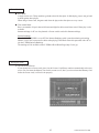
(1) The Card Check Screen
If you already have a license card, place it in the License Card Slot to continue automatically to the next
screen. You can insert the Memory Card in this screen as well, but if you do not insert the Memory Card
before the license card, it will not work properly.
43
www.seuservice.com
(2) The F-ZERO LICENSE CARD Screen
Press down on the accelerator in the Card Check Screen to move to the Purchase Screen. When creating
a new card, insert the required number of coins to make a new license card. When your license card's
credits have been used up, you will be moved to the Renewing Purchase Screen.
You can insert the Memory Card in this screen as well, but if you do not insert the Memory Card before
the license card, it will not work properly.
<Creating a new card>
<Renewing>
(3) The NAME ENTRY Screen (Shown the first time a license card is purchased)
When you purchase a new license card, you are moved to the Name Entry Screen.
(Inappropriate words will be changed into asterisks.)
(4) The LICENSE CARD Screen
(Not shown if a license card is not used)
Shows your personal car and play information.
www.seuservice.com
44
(5) The MODE SELECT Screen
Choose either RACE MODE or TIME ATTACK MODE. Different descriptions will appear below based
on the cabinet and Test Mode settings. In Versus Play, select the race mode while holding down the brake
to bypass the Versus Screen.
(6) The VERSUS Screen
(When linked and playing Race Mode.)
When you choose Race Mode in the usual way, you will be taken to the Versus Screen. Empty cabinets
will display a similar screen.
If you are using a license card, Race Mode-related data will appear. If others are also using license cards,
you can take a look at their data. The layout of the screen differs according to the number of linked
cabinets (though the information shown is the same).
* You cannot skip this screen.
<2 cabinets linked>
<3-4 Cabinets linked>
45
www.seuservice.com
(7) The COURSE SELECT Screen
Select your favorite course from the six available. In Time Attack Mode, you can also configure Ghost
settings. (Use the pedal lever to choose a ghost.) If you are using a License Card, you can look at
information on each course. In Race Mode, wins, win percentage, and other data appear. In Time Attack
Mode, total time, best lap, and max speed are shown.
< Race Mode>
<Time Attack Mode>
(8) The MACHINE SELECT Screen
Select your machine. You always get to choose machines, regardless of your card.
The machines you can choose from change based on the card(s) you've inserted.
- No Card:
Select from the default 14 machines.
- License Card: Select from 15 machines, including your own on the far left.
- Memory Card: Adds machines from your F-ZERO GX garage on the far right.
If there are no cars in your F-ZERO GX garage, no machines will appear.
www.seuservice.com
46
(9) The MACHINE SETTING Screen
Use the graph to configure your machine.
In multiplayer Race Mode, you can view other players' machines. If you are using a License Card in
Time Attack Mode, you can look at best total times, machines used and settings.
If there is no data, NO DATA appears.
<Race Mode>
<Time Attack Mode>
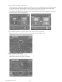
(10) Race
This is the racing screen. The basic controls of the machine are the steering wheel and the accelerator.
You can use the booster after the second lap, so feel free to press the button in the center of the steering
wheel. When the booster is used, the energy drain rate increases. If energy reaches zero and your machine
takes damage, your machine will flash red, you will be unable to move, and an official car will come with
extra energy. If you leave the course, an official car will come to return your machine to the course.
Lap Time
Energy Meter
Time Left
Time
Laps
<Race Mode>
Rank
Top 6
You
Your speed
Course Radar
<Time Attack Mode>
47
www.seuservice.com
(11) VS RESULT Screen
When you complete the race, the results of the race appear. Results do not appear when you retire. The
display for COM races and multiplayer races are different in Race Mode. In Time Attack Mode, your
personal best and other data are also shown if you use a license card.
<Race Mode: COM>
<Race Mode: Multiplayer>
<Time Attack Mode>
(12) RESULTS Screen (Race Mode), TIME ATTACK RANKING Screen (Time Attack Mode)
The Results Screen shows the results of the race, while the Time Attack Ranking Screen shows the best
times recorded in the cabinet. When using a License Card, your username is automatically entered. If you
are not using a License Card, you can enter a three-letter rankings name.
<Race Mode>
<Time Attack Mode>
(13) The PILOT POINTS Screen
(Only with License Card)
Gives you Pilot Points based on your race performance.
Points are added and totaled for each category.
When your Pilot Points exceed the required value, you are congratulated and moved to the Configuration
Screen. This screen also informs you of Pilot Rank promotions.
www.seuservice.com
48
(14) The CONFIGURATION Screen
(Only with a License Card and sufficient Pilot Points)
Lets you switch out your personal machine's parts and change pilots. Changing parts and pilots costs
Pilot Points. When you change machine parts, the old parts are disposed of.
(15) Memory Card Screen
(Only with a Nintendo GameCube Memory Card inserted)
If you play with a Memory Card inserted and satisfy certain conditions, you can download special FZERO AX data to your Memory Card. You can then use the downloaded data in F-ZERO GX.
49
www.seuservice.com
(16) The PASSWORD Screen
(Only with a License Card, when playing Time Attack Mode, and when the course has completed data)
Once you complete a course in Time Attack Mode, you are taken to the Password Screen and given a
password. This password is for your best total time. It is shown every time, but it is not necessarily the
password for the race.
Enter the ID and name written to your License Card and the password shown on this screen into the
F-ZERO Official Home Page to join the Internet Rankings. The Internet Rankings are announced on the
F-ZERO Official Home Page (http://f-zero.jp/).
Set PASSWORD DISP to OFF in GAME ASSIGNMENTS in Test Mode to hide this screen.
You cannot continue to the next screen until the License Card is removed.
(17) The GAME OVER Screen
This screen is shown when the game is over. A reminder regarding your card is shown.
And if your license card will need to be renewed next time, this screen will indicate that.
www.seuservice.com
50
Other Warnings
Error Display
Basic errors related to magnetic cards and memory cards cause detailed instructions to appear on the
screen. Mechanical errors in the cabinet, however, are displayed with error numbers. The following is a
description of those errors. (See 18-3.)
Error 05: Steering : I/O Error
Error 06: Steering : Overheat/Overload Error
Error 07: Steering : Encoder Error
Error 08: Steering : Excess Current Error
Secret Codes
Race Mode: "No Versus"
• Description: Play by yourself, with no VERSUS screen.
• To access: Hold down the brake when selecting a race mode in the MODE SELECT screen. This is
explained in the MODE SELECT Screen help.
Note:No Versus cannot be used when there is only one cabinet.
Race Mode: "VS BATTLE" (Human-only race)
• Description: A race with only human competitors. COM machines cannot join the race. For two to
four players.
• To access: Each participant must hold down the brake when selecting their machine in the MACHINE
SELECT screen.
Note: Cannot be used with only one cabinet or in one-player play. COM machines will always join.
Race Mode: "No Handicap"
• Description: In Race Mode, cars in the rear are given supplemental speed and can go faster (playercontrolled machines only). To turn off supplemental speed, use No Handicap.
• To access: All players (even in one-player races) must hold down the brake when selecting a machine
from the Machine Settings Screen.
Note: In Race Mode, even one-player games are handicapped, so use the above to turn handicapping
OFF.
Time Attack: Racing Staff Ghosts
• Description: Lets you race against Staff Ghosts
• To access: Hold down the brake with the cursor on "Champion Ghost" in the Course Selection Screen
and select a course.
51
www.seuservice.com
10. TEST AND DATA DISPLAY
Do not touch the machine until it has competed the initialization process and the
advertising screen has appeared. Doing so may cause the person touching the machine to
be struck by the seat. It may also prevent the machine from initializing properly. Failure
to initialize properly can lead to control malfunction and other problems.
By operating the switch unit, periodically perform the tests and data check. When installing the machine
initially or collecting cash, or when the machine does not function correctly, perform checking in
accordance with the explanations given in this section.
The following shows tests and modes that should be utilized as applicable.
This product's basic system consists of the TRIFORCE game board and the GD-ROM drive.
The product supports, therefore, the following 2 test modes:
(1) System test mode for an automatic self-diagnostic test (generally used by every product that contains
the basic system) and a coin assignment (specifically used by this product) and
(2) Game test mode for testing the input/output control devices and setting the difficulty level
(specifically used by this product).
TABLE 10 EXPLANATION OF TEST MODE
ITEMS
DESCRIPTION
INSTALLATION
OF MACHINE
When the machine is installed, perform the following:
1. Check to ensure each is the standard setting at shipment.
2. Check each Input equipment in the INPUT TEST mode.
3. Check each Output equipment in the OUTPUT TEST mode.
4. Test on-IC-Board IC's in the SELF-TEST mode.
MEMORY TEST
This test is automatically executed by selecting MEDIA BOARD
TEST, or SYSTEM INFORMATION in the Menu mode.
PERIODIC
SERVICING
Periodically perform the following:
1. MEMORY TEST
2. Ascertain each setting.
3. To test each Input equipment in the INPUT TEST mode.
4. To test each Output equipment in the OUTPUT TEST mode.
CONTROL
SYSTEM
1. To check each Input equipment in the INPUT TEST mode.
2. Adjust or replace each Input equipment.
3. If the problem still remains unsolved, check each equipment's
mechanism movements.
MONITOR
In the Monitor Adjustment mode, check to see if Monitor (Projector) adjustments are appropriate.
IC BOARD
MEMORY TEST
DATA CHECK
Check such data as game play time and histogram to adjust the
difficulty level, etc.
www.seuservice.com
52
10-1 SWITCH UNIT AND COIN METER
WARNING!
STOP
IMPORTANT!
Never touch places other than those specified. Touching places not specified can cause
electric shock and short circuit accidents.
Adjust the sound to the optimum volume, taking into consideration the environmental
requirements of the installation location.
Removing the Coin Meter circuitry renders the game inoperable.
SWITCH UNIT
Open the coin chute door, and the switch unit shown will
appear.
The functioning of each SW is as follows:
FIG. 10. 1 a SWITCH UNIT
(1)TEST BUTTON:
(TEST)
(2)SERVICE BUTTON:
(SERVICE)
For the handling of the test button, refer to the following pages.
Gives credits without registering on the coin meter.
(3)DEMAGNETIZER SWITCH: Eliminates the on-screen color unevenness due to magnetization
of CRT. First use this SW before performing the monitor's color
(DEMAG)
adjustment.
(4)VOLUME CONTROL:
(FRONT SP. VOL)
Adjusts the volume of the speakers on the left and right sides of the
monitor.
(5)VOLUME CONTROL:
(REAR SP. VOL)
Adjusts the volume of the speakers on the left and right of the seat
headrest.
COIN METER
Open the Cashbox Door by using the key to have
the Coin Meter appear underneath the Cashbox.
COIN METER
FIG. 10. 1 b
53
www.seuservice.com
10-2 SYSTEM TEST MODE
STOP
IMPORTANT!
Any settings that are changed by users during TEST MODE are saved upon
exiting TEST MODE with the EXIT command in the SYSTEM MENU. If the
unit is powered off prior to exiting, changes to settings will not take effect.
You may not enter GAME TEST MODE while the unit is reading from or
checking the GD-ROM. If error messages are displayed when exiting TEST
MODE, you should power the unit off and on again.
The following settings should be set as indicated for this product.
Coin Chute Type:
Common
Service Type:
Common
Network Type:
Ether
10-2A SYSTEM TEST MENU
SYSTEM TEST MODE is used primarily to check if boards are functioning properly, to adjust monitor
colours and change coin/credit settings.
Press the TEST Button after powering on the unit to display the following SYSTEM MENU.
SYSTEM MENU
RAM TEST
MEDIA BOARD TEST
SYSTEM INFORMATION
JVS TEST
SOUND TEST
C.R.T. TEST
COIN ASSIGNMENTS
CLOCK SETTING
NETWORK SETTING
ENTER GAME TEST
[*******************]
→EXIT
SELECT WITH SERVICE BUTTON
AND PRESS TEST BUTTON
Press the SERVICE Button to move the cursor to the desired test item.
Move the cursor to the desired item and press the TEST Button to display each test screen.
Move the cursor to ENTER GAME TEST and press the TEST Button to enter the individual test menus
for each game. Refer to "10-3 GAME TEST MODE".
When testing is complete, move the cursor to EXIT and press the TEST Button. The game advertisement
screen should be displayed.
www.seuservice.com
54
10-2B RAM TEST
Use RAM TEST to run a check of the TRIFORCE MAIN BOARD memory IC.
��������RAM�TEST
����AUX�MEMORY����GOOD
PRESS�TEST�BUTTON�TO�EXIT
RAM TEST begins immediately upon entering this test mode.
If "GOOD" is displayed at the right-hand side of the screen, memory IC is functioning properly.
After the test is complete, move the cursor to EXIT and press the TEST Button to return to the SYSTEM
MENU screen.
55
www.seuservice.com
10-2C MEDIA BOARD TEST
STOP
IMPORTANT!
Powering off the system during the MEDIA BOARD TEST with a DIMM BOARD will
erase the game programme data. It may be necessary to reload the data.
Always wait for the test to complete before attempting to exit.
MEDIA BOARD TEST is used to check the memory and IC on the MEDIA BOARD connected to the
TRIFORCE. Test screens and test times may differ depending on the type of MEDIA BOARD connected
to the unit.
���MEDIA�BOARD�TEST��1/2
����DIMM�BOARD(TYPE�3)
����VERSION��****
����STATUS���GOOD
����CHECKING�100%
����DIMM�TEST
����DIMM0�����-�GOOD
����DIMM1�����-�NONE
����GD-ROM����-�GOOD
PRESS�TEST�BUTTON�TO�EXIT
FIG 10. 2 c a MEDIA BOARD TEST Screen (1/2)
MEDIA BOARD TEST begins immediately upon entering this test mode.
If "GOOD" is displayed to the right of each item, the MEDIA BOARD components are functioning
properly.
Press the TEST Button to move to Screen 2/2.
Press the TEST Button on Screen 2/2 to return to the SYSTEM MENU screen.
���MEDIA�BOARD�TEST��2/2
��NETWORK�BOARD
��VERSION��****
��STATUS���GOOD
��CHECKING�100%
��NETWORK�BOARD�TEST
��RAM�CHECK�_�GOOD
����--��COMPLETED��--
PRESS�TEST�BUTTON�TO�EXIT
FIG 10. 2 c a MEDIA BOARD TEST Screen (2/2)
www.seuservice.com
56
10-2D SYSTEM INFORMATION
Use SYSTEM INFORMATION to check version and other information for system programmes.
Screens may differ depending on the type of MEDIA BOARD connected to the unit.
����SYSTEM�INFORMATION
��MAIN�BOARD
����REGION���������****
����BOOT�VERSION���****
����FIRM�VERSION���****
����FPGA�VERSION���****
����SERIAL�NO.�***************
��MEDIA�BOARD
���DIMM�BOARD(TYPE�3)�+�GDROM
����MEMORY�SIZE����512MB
����FIRM�VERSION���****
����SERIAL�NO.�***************
���NETWORK�BOARD
����FIRM�VERSION���*****
(A)
(B)
(B)
(B)
(C)
(D)
(E)
(F)
(G)
(F)
PRESS�TEST�BUTTON�TO�EXIT
Press the TEST Button to return to the SYSTEM MENU screen.
(A)
REGION
The COUNTRY CODE of the MAIN BOARD.
(B)
BOOT VERSION, FIRM VERSION, FPGA VERSION
Version information for the MAIN BOARD system programmes.
(C)
SERIAL NO.
Serial number of the MAIN BOARD.
(D)
DIMM BOARD + GDROM
Type of MEDIA BOARD. This example shows a DIMM BOARD (TYPE 3) with a
GD-ROM DRIVE connected.
(E)
MEMORY SIZE
Capacity of DIMM memory installed on the DIMM BOARD.
(F)
FIRM VERSION
Version information for the DIMM BOARD system programme.
(G)
SERIAL NO.
Serial number of the DIMM BOARD.
57
www.seuservice.com
10-2E JVS TEST
JVS TEST is used to verify the specs of the I/O BOARD connected to the TRIFORCE and to run input
tests.
I/O BOARD specs are displayed initially.
�����������JVS�TEST
����������INPUT�TEST
����������NEXT�NODE
��������→EXIT
NODE�������1/1
NAME�������****************
�����������I/O�BD�JVS
�����������*********
�����������Ver****
CMD�VER����1.1
JVS�VER����2.0
COM�VER����1.0
SWITCH�����2�PLAYER(S)��12�BITS
COIN�������2�SLOT
ANALOG�����8�CH
ROTARY�����0�CH
KEYCODE����0
SCREEN�����X:0�Y:0�CH:0
CARD�������0�SLOT
HOPPER�OUT�0�CH
DRIVER�OUT�22�CH
ANALOG�OUT�0�CH
CHARACTER��CHARA:0�LINE:0
BACKUP�����0
��SELECT�WITH�SERVICE�BUTTON
����AND�PRESS�TEST�BUTTON
Use the SERVICE Button to move the cursor to the desired test item.
Move the cursor to INPUT TEST and press the TEST Button to enter the INPUT TEST screen for the I/O
BOARD currently displayed.
When 2 or more I/O BOARDS are connected, move the cursor to NEXT NODE and press the TEST
Button to enter the test screen for the next I/O BOARD. The lower the NODE number, the further away
the node is from the TRIFORCE.
Move the cursor to EXIT and press the TEST Button to return to the SYSTEM MENU screen.
www.seuservice.com
58
INPUT TEST Screen
��������������JVS�TEST
�������������INPUT�TEST
����NODE�������1/1
������SYSTEM�����00
������PLAYER�1���0000
������PLAYER�2���0000
������COIN�1�����0000
������COIN�2�����0000
������ANALOG�1���0000
������ANALOG�2���0000
������ANALOG�3���0000
������ANALOG�4���0000
������ANALOG�5���0000
������ANALOG�6���0000
������ANALOG�7���0000
������ANALOG�8���0000
(A)
(A)
(A)
(B)
(B)
(C)
(C)
(C)
(C)
(C)
(C)
(C)
(C)
PRESS�TEST�AND�SERVICE�BUTTON�TO�EXIT
On-screen values change according to the input from switches and the volume.
(A)
SYSTEM, PLAYER
Values change with input from control panel/other switches.
(B)
COIN
Increases with input from the COIN SWITCH. The count is cleared when exiting TEST MODE.
(C)
ANALOG
Displays analog values from "0000" to "FF00".
Press the SERVICE and TEST Buttons simultaneously to return to the JVS TEST main screen.
59
www.seuservice.com
10-2F SOUND TEST
Use SOUND TEST to test sound output and to toggle the stereo/mono setting.
��������SOUND�TEST
��OUTPUT�TYPE�������STEREO
��RIGHT�SPEAKER�����OFF
��LEFT��SPEAKER�����OFF
→EXIT
(A)
(B)
(B)
SELECT�WITH�SERVICE�BUTTON
��AND�PRESS�TEST�BUTTON
Use the SERVICE Button to move the cursor to the desired test item.
Press the TEST Button to enter the selected item.
(A)
OUTPUT TYPE(STEREO, MONO)
Toggle the sound output from the I/O PANEL audio output interface setting between STEREO and
MONO.
Set to STEREO in this game machine.
(B)
RIGHT/LEFT SPEAKER(ON, OFF)
When set to "ON", the test sends a beep to each right and left audio output interface. Only the
word "SPEAKER" is displayed when the OUTPUT TYPE is set to "MONO", and when set to
"ON", the test sends the same beep to both the left/right audio output interfaces.
Move the cursor to EXIT and press the TEST Button to return to the SYSTEM MENU screen.
www.seuservice.com
60
10-2G C.R.T. TEST
Use the C.R.T. TEST to adjust monitor colours and verify screen size.
COLOUR CHECK Screen
Monitor COLOUR CHECK screen is displayed initially.
Each of the colours (red, green and blue) is darkest at the far left and gets progressively lighter (32 steps)
towards the right.
Monitor brightness is set correctly if the white colour bar is black at the left edge and white at the right
edge.
�����������������C.R.T.�TEST�1/2
���������������������EDIT
�����1�������������→NEXT���������������32
RED
GREEN
BLUE
WHITE
����������SELECT�WITH�SERVICE�BUTTON
������������AND�PRESS�TEST�BUTTON
Use the SERVICE Button to move the cursor to the desired test item.
Move the cursor to EDIT and press the TEST Button to enter COLOUR ADJUST mode.
Move the cursor to NEXT and press the TEST Button to enter the SIZE CHECK screen.
SIZE CHECK Screen
C.R.T.�TEST�2/2
PRESS�TEST�BUTTON�TO�EXIT
Adjust the CHECK GRID so that the entire GRID is displayed on the screen.
Press the TEST Button to return to the SYSTEM MENU screen.
61
www.seuservice.com
COLOUR ADJUST MODE Screen
This mode is for monitors that do not have colour adjustment features.
Normally the colour should be adjusted through the monitor.
Use the SERVICE Button to move the cursor to the item to be adjusted.
Press the TEST Button to enter the selected item.
��������������C.R.T.�TEST�1/2
������������VIDEO�PARAMETER�EDIT
�����1���������������������������������32
������������BRIGHTNESS��14
������������CONTRAST����26
������������CONTRAST_R�255
������������CONTRAST_G�255
������������CONTRAST_B�255
������������AUTO�ADJUST
����������→EXIT
(A)
(B)
(C)
(D)
(E)
(F)
���������SELECT�WITH�SERVICE�BUTTON
�����������AND�PRESS�TEST�BUTTON
(A)
BRIGHTNESS(10-60)
Adjust the brightness of the screen.
(B)
CONTRAST(10-44)
Adjust the colour contrast.
(C)
CONTRAST_R(155-255)
Adjust the RED contrast.
(D)
CONTRAST_G(155-255)
Adjust the GREEN contrast.
(E)
CONTRAST_B(155-255)
Adjust the BLUE contrast.
(F)
AUTO ADJUST
Adjust colour settings automatically.
Move the cursor to EXIT and press the TEST Button to enter the SIZE CHECK screen.
www.seuservice.com
62
10-2H COIN ASSIGNMENTS
Use COIN ASSIGNMENTS to set the credit rate for each coin inserted.
Use the SERVICE Button to move the cursor to the desired test item.
Press the TEST Button to change the setting or to open the detailed settings.
Move the cursor to EXIT and press the TEST Button to return to the SYSTEM MENU screen.
���������COIN�ASSIGNMENTS
���������COIN�ASSIGNMENTS
��COIN�CHUTE�TYPE�������COMMON
��SERVICE�TYPE����������COMMON
(A)
(B)
��COIN�CHUTE�TYPE�������INDIVIDUAL
��SERVICE�TYPE����������INDIVIDUAL
��COIN�CHUTE�#1�COIN�TO�CREDIT�RATE
��1�COIN(S)�COUNT�AS�1�CREDIT(S)
��COIN�CHUTE�#2�COIN�TO�CREDIT�RATE
��1�COIN(S)�COUNT�AS�1�CREDIT(S)
��DETAIL�SETTING
��GAME�COST�SETTING
→EXIT
(C)
��COIN�CHUTE�#1�COIN�TO�CREDIT�RATE
��1�COIN(S)�COUNT�AS�1�CREDIT(S)
(C)
(D)
(H)
����SELECT�WITH�SERVICE�BUTTON
������AND�PRESS�TEST�BUTTON
����SELECT�WITH�SERVICE�BUTTON
������AND�PRESS�TEST�BUTTON
COIN CHUTE TYPE…COMMON
(A)
��DETAIL�SETTING
��GAME�COST�SETTING
→EXIT
COIN CHUTE TYPE…INDIVIDUAL
COIN CHUTE TYPE(COMMON, INDIVIDUAL)
Adjust settings according to the specs of the cabinet COIN CHUTE.
Set to COMMON in this game machine.
COMMON
This is for cabinets where a single COIN CHUTE is used by multiple players.
Coins inserted by each player are treated as common credits.
Up to 2 COIN CHUTES (#1 and #2) may be used. The (C) COIN TO CREDIT RATE setting for COIN
CHUTE #1 and #2 may be set differently.
INDIVIDUAL
This is for cabinets with individual COIN CHUTES for each player.
Coins inserted by each player are treated as individual player credits.
The (C) COIN TO CREDIT RATE setting is used by all COIN CHUTES.
(B)
SERVICE TYPE(COMMON, INDIVIDUAL)
Use this to set the function of each SERVICE Button when there is more than one SERVICE Button.
Set to COMMON in this game machine.
COMMON
Pressing any SERVICE Button enters service credits for all players.
INDIVIDUAL
Pressing the SERVICE Button enters service credits only for the corresponding player.
63
www.seuservice.com
(C)
COIN TO CREDIT RATE
Set the CREDIT RATE for each coin inserted.
The "x COIN(S) COUNT AS y CREDIT(S)" setting indicates that "Inserting x coins equals y credits".
Set this to "FREE PLAY" to allow game play without credits.
When (A) COIN CHUTE TYPE is set to "COMMON", COIN CHUTE #2 settings are restricted to some
extent by the settings for COIN CHUTE #1.
(D)
DETAIL SETTING
This mode allows for more detailed credit rate settings than the (C) COIN TO CREDIT RATE setting.
Changes made in DETAIL SETTING override any (C) COIN TO CREDIT RATE settings.
DETAIL SETTING Screen
���������COIN�ASSIGNMENTS
����������DETAIL�SETTING
��COIN�CHUTE�#1�MULTIPLIER
����1�COIN�COUNT�AS�1�COIN(S)
��COIN�CHUTE�#2�MULTIPLIER
����1�COIN�COUNT�AS�1�COIN(S)
��BONUS�ADDER���������NO�BONUS�ADDER
��COIN�TO�CREDIT���1�COIN(S)�1�CREDIT
→EXIT
�COIN�CHUTE�#1�OPERATION
�COIN���1��2��3��4��5��6��7��8��9
�CREDIT�1��2��3��4��5��6��7��8��9
�COIN�CHUTE�#2�OPERATION
�COIN���1��2��3��4��5��6��7��8��9
�CREDIT�1��2��3��4��5��6��7��8��9
����SELECT�WITH�SERVICE�BUTTON
������AND�PRESS�TEST�BUTTON
(E)
���������COIN�ASSIGNMENTS
����������DETAIL�SETTING
��COIN�CHUTE�#1�MULTIPLIER
����1�COIN�COUNT�AS�1�COIN(S)
(E)
(F)
(G)
��BONUS�ADDER���������NO�BONUS�ADDER
��COIN�TO�CREDIT���1�COIN(S)�1�CREDIT
→EXIT
�COIN�CHUTE�#1�OPERATION
�COIN���1��2��3��4��5��6��7��8��9
�CREDIT�1��2��3��4��5��6��7��8��9
����SELECT�WITH�SERVICE�BUTTON
������AND�PRESS�TEST�BUTTON
COIN CHUTE TYPE…COMMON
COIN CHUTE TYPE…INDIVIDUAL
(E)
COIN CHUTE MULTIPLIER
Use this to set how many coins will be counted for each coin inserted.
The "1 COIN COUNT AS x COIN(S)" setting indicates that "Each coin will be counted as x coins".
When the (A) COIN CHUTE TYPE is set to "COMMON", the setting may be set individually for COIN
CHUTE #1 and #2.
(F)
BONUS ADDER
Use this to set the number of coins calculated with the (E) COIN CHUTE MULTIPLIER setting that
need to be inserted to get 1 bonus coin. When the (A) COIN CHUTE TYPE is set to "COMMON", the
sum of the coins for COIN CHUTE #1 and #2 is used for the calculation.
The "x COINS GIVE 1 EXTRA COIN" setting indicates that "For every x coins, 1 bonus coin is given".
Set this to "NO BONUS ADDER" to disable bonus coins entirely.
(G)
COIN TO CREDIT
Use this to set how many coins calculated with the (F) BONUS ADDER setting count as 1 credit.
The "x COIN(S) 1 CREDIT" setting indicates that "Every x coins equals 1 credit."
www.seuservice.com
64
(H)
GAME COST SETTING
Use this mode to set the number of credits required to start a game.
���������COIN�ASSIGNMENTS
���������GAME�COST�SETTING
��2�CREDIT�TO�START
��1�CREDIT�TO�BUY�A�LICENSE�CARD
(I)
(J)
→EXIT
����SELECT�WITH�SERVICE�BUTTON
������AND�PRESS�TEST�BUTTON
(I)
Set the number of credits required to start a game.
(J)
Set the number of credits required to buy a license card.
65
www.seuservice.com
10-2I CLOCK SETTING
Use CLOCK SETTING to set the TRIFORCE internal clock.
������CLOCK�SETTING
2003/06/20(FRI)��05:10:34
���������YEAR
���������MONTH
���������DAY
���������HOUR
���������MINUTE
�������→EXIT
SELECT�WITH�SERVICE�BUTTON
��AND�PRESS�TEST�BUTTON
Use the SERVICE Button to move the cursor to the item to be set.
Move the cursor to the desired item and press the TEST Button to increase values.
The max value for YEAR is "2099"; further increases return the value to "2000".
Move the cursor to EXIT and press the TEST Button to return to the SYSTEM MENU screen.
www.seuservice.com
66
10-2J NETWORK SETTING
STOP
IMPORTANT!
This product should only be used with the factory settings indicated in this manual.
Selecting certain options from the screens listed below may alter settings or bring up
other screens. However, since these functions are not used by this machine, they are not
described in this manual.
In the event that settings are altered on a screen not mentioned in this manual, the
machine may cease to function properly. Restore the settings to the values shown on the
screens below.
Refer to "10-3E Network Settings" for actual network play settings.
Use NETWORK SETTING to establish and test network connections.
Use the SERVICE Button to move the cursor to the desired test item.
Press the TEST Button to change the setting or to open the detailed settings.
Move the cursor to EXIT and press the TEST Button to return to the SYSTEM MENU screen.
�������NETWORK�SETTING
��NETWORK�TYPE�������ETHER
(A)
��SET�IP�ADDRESS
(B)
��CLEAR�NETWORK�SETTING
��NETWORK�TEST
->EXIT
��SELECT�WITH�SERVICE�BUTTON
����AND�PRESS�TEST�BUTTON
(A)
NETWORK TYPE
Choose a type of the communication network.
Set to ETHER in this game machine.
NONE:
Sets that the communication system does not perform. Sets to NONE when you
don't set the network system.
ETHER:
Sets ETHER for the communication network.
MOBILE:
Sets a mobile communication terminal for the communication network.
ETHER/MOBILE
DEFAULT ETHER:
ETHER/MOBILE
DEFAULT MOBILE:
Set ETHER or MOBILE automatically for the communication network.
Priority is given to ETHER.
Set ETHER or MOBILE automatically for the communication network.
Priority is given to MOBILE.
67
www.seuservice.com
(B)
SET IP ADDRESS
This sets up the details of the communication network. Depending on the NETWORK TYPE setting, the
contents of setting vary. If setting to NONE, it does not appear.
ETHER Setting
����SET�IP�ADDRESS�1/1
REMOTE�����������DISABLE����������(C)
������IP�ADDRESS(E)
��������*******
������SUBNET�MASK(E)
----.----.----.--- GATEWAY(E)
----.----.----.--- PRIMARY�DNS
----.----.----.--- SECONDARY�DNS
----.----.----.--- ->EXIT
SELECT�WITH�SERVICE�BUTTON
AND�PRESS�TEST�BUTTON
(C)
REMOTE
This option determines whether network settings will be handled automatically.
For this machine, the option should be set to DISABLE.
The other items are set up automatically. It's not necessary to change anything.
www.seuservice.com
68
10-3 GAME TEST MODE
STOP
IMPORTANT!
When changing the game configuration, changes will not be enabled until the Game
Test Mode has been completed. Be sure to exit the Game Test Mode properly after
configuration changes.
Do not configure the game in ways not described in this text, as this may lead to
game malfunctions.
10-3A GAME TEST MENU
Select GAME TEST MODE from the System Menu screen to display the Game Test Menu screen as
follows.
Use the SERVICE Button to move the cursor to the desired test item. Press the TEST Button to enter the
selected item.
After selecting an item, read the explanations below regarding operation.
��F-ZERO�AX�TEST�MENU
��������INPUT�TEST�����������������������
��������OUTPUT�TEST����������������������
��������GAME�ASSIGNMENTS�����������������
��������NETWORK�SETTING������������������
��������CARD�TEST������������������������
��������CALIBRATION����������������������
��������RACE�RECORD����������������������
��������BOOKKEEPING����������������������
��������BACKUP�DATA�CLEAR����������������
����->EXIT
(10-3B)
(10-3C)
(10-3D)
(10-3E)
(10-3F)
(10-3G)
(10-3H)
(10-3I)
(10-3J)
SELECT�WITH�SERVICE�BUTTON
����AND�PRESS�TEST�BUTTON
FIG. 10. 3 a GAME TEST MENU Screen
After making changes, be sure to select EXIT and press the TEST Button in order to enable the new
settings.
Move the cursor to EXIT and press the TEST Button to return to the System Menu screen.
69
www.seuservice.com
10-3B INPUT TEST
Select INPUT TEST to display the following screen and check the status of input devices.
This test should be used periodically to check that each input device is functioning correctly.
�����������������������INPUT�TEST
STEERING��X�����0(~FF)�������SERVICE��������OFF(ON)
STEERING��Y�����0(~FF)�������TEST�����������OFF(ON)
PADDLE��LEFT����OFF(ON)
PADDLE��RIGHT���OFF(ON)
BOOST�����������OFF(ON)�
GAS�������������0(~FF)
BRAKE�����������0(~FF)
START�BUTTON
VIEW�CHANGE�1���OFF(ON)
VIEW�CHANGE�2���OFF(ON)
VIEW�CHANGE�3���OFF(ON)
VIEW�CHANGE�4���OFF(ON)
�������PRESS�TEST�AND�SERVICE�BUTTON�TO�EXIT
FIG. 10. 3 b a INPUT TEST Screen
STEERI NG X
START BUTTON
BOOST
STEERI NG Y
L/R
MAGNETIC CARD R /W
F/B
VIE W CHANGE 1~4
PADDLE RIGH T
MEMOR Y CARD SLOT
PADDLE LE FT
BRAKE
GAS
FIG. 10. 3 b b
Test the STEERING, GAS and BRAKE controls to ensure that they are functioning properly and that the
parameters change smoothly as each input device is operated.
If the other input devices (switches, buttons) switch from "OFF" to "ON" when operated, they are
functioning normally.
Press the SERVICE and TEST Buttons simultaneously to return to the Game Test Menu screen.
www.seuservice.com
70
10-3C OUTPUT TEST
CAUTION!
Select STEERING and press the TEST Button to make the steering wheel turn. To
avoid injury, first make sure that no one is touching the wheel.
To avoid injury, first check that no one is touching the steering wheel. Select
OUTPUT TEST and press the TEST Button. After initialization the steering wheel
will turn.
Selecting OUTPUT TEST and pressing the TEST Button will cause the next screen to initialize and load.
This allows you to check the status of each output device.
This test should be used periodically to check that the lamps are functioning correctly.
�����������OUTPUT�TEST�
���START�BUTTON������������OFF(ON)
���VIEW�CHANGE�1�����������OFF(ON)
���VIEW�CHANGE�2�����������OFF(ON)
���VIEW�CHANGE�3�����������OFF(ON)
���VIEW�CHANGE�4�����������OFF(ON)
���BOOST�������������������OFF(ON)
���STEERING
�����CENTER����������������OFF(ON)
�����LEFT������������������OFF(ON)
�����RIGHT�����������������OFF(ON)
->�EXIT�
���SELECT�WITH�SERVICE�BUTTON
�����AND�PRESS�TEST�BUTTON
FIG. 10. 3 c a OUTPUT TEST Screen
STEE R ING
STAR T BUTTON
BOOST
L/R
VIEW CHANGE 1 ~4
FIG. 10. 3 c b
71
www.seuservice.com
The START BUTTON, VIEW CHANGE 1-4, and BOOST allow you to check the status of the lights on
top of the control panel. Select each item and press the TEST Button to turn the respective light on and
off as indicated by the display to the right of the item.
Come to this screen periodically to check that the lamps light up with ON and turn off with OFF.
When you select STEERING and press the TEST Button, it will move in the selected direction for a set
period of time and stop.
Move the cursor to EXIT and press the TEST Button to return to the Game Test Menu screen.
www.seuservice.com
72
10-3D GAME ASSIGNMENTS
Select GAME ASSIGNMENTS to display the current game settings and make changes.
Periodically come to this screen to check game settings.
������������������GAME ASSIGNMENTS
�����ADVERTISE�SOUND��������ON(OFF)
�����FORCE�FEEDBACK���������2(1~3)
�����MAGNETIC�CARD�R/W�USE��ON(ON→OFF→OUT�OF�SERVICE)
�����MEMORY�CARD�SLOT�USE���ON(ON→OFF→OUT�OF�SERVICE)
�����GAME�DIFFICULTY��������NORMAL(VERY�EASY→EASY→NORMAL→HARD→HARDEST)
�����HANDICAP���������������ON(OFF)
�����VS�BATTLE�MODE���������OFF(ON)
�����PASSWORD�DISP����������ON(OFF)
�����RACE�MODE�LAPS���������NORMAL(SET1~5)
�������1[Sonic�Oval]��������8(10→15→20→30→40)
�������2[Screw�Drive]�������6(�8→10→15→20→30)
�������3[Meteor�Stream]�����4(�6→�8→10→15→20)
�������4[Cylinder�Wave]�����3(�5→�7→�9→10→15)
�������5[Thunder�Road]������3(�5→�7→�9→10→15)
�������6[Spiral]������������3(�5→�7→�9→10→15)
->��EXIT
������������SELECT WITH SERVICE BUTTON
��������������AND PRESS TEST BUTTON
FIG. 10. 3 d GAME ASSIGNMENTS
Press the SERVICE Button and move the cursor to the setting you wish to change. Press the TEST
Button to cycle the parameters on the left of the item through its various settings.
Note that GAME DIFFICULTY, HANDICAP, VS BATTLE MODE, PASSWORD DISP and RACE
MODE LAPS are shown on the machine whose NUMBER on the NETWORK SETTING screen is set to
1.
Changing the configuration of the NUMBER 1 machine automatically follows the settings of the other
numbered machines.
ADVERTISE SOUND
Turn advertising sound output ON and OFF.
(Default setting: ON)
FORCE FEEDBACK
There are three settings for steering resistance. (Default setting: 2)
1: Weak
2: Normal
3: Strong
MAGNETIC CARD R/W USE
Configure the usability of the card reader/writer. Turn the card reader/writer on and off. (Default setting:
ON)
Set it to ON if you want to activate card reader/writer, and to OUT OF SERVICE or OFF if a malfunction
or other factor makes the card reader/writer unusable.
• If you set this option to OUT OF SERVICE, the advertising loop (demo screen) will display the
message, "The F-ZERO LICENSE CARD can not be used or purchased at this time," and users will
be unable to play with license cards.
• If you set this option to OFF, no message regarding license cards will be shown during the advertising
loop.
73
www.seuservice.com
MEMORY CARD SLOT USE
Configure Nintendo GameCube Memory Card usage. This option lets you enable or disable the memory
card slot. (Default setting: ON)
• Set this option to ON to enable compatibility with F-ZERO GX for the Nintendo GameCube.
Note that this option cannot be used if the player does not have F-ZERO GX game data.
• If you set this option to OUT OF SERVICE, the advertising loop will display the message, "Can not
use Nintendo GameCube Memory Card."
• If you set this option to OFF, no message regarding the Memory Card will be shown during the
advertising loop.
NOTES:
• If both license cards and memory cards are set to OUT OF SERVICE, the advertising loop will
display the message, "Cards cannot be used."
• If both are set to OFF, no message will be shown.
• If one of the two is set to OUT OF SERVICE, the message specific to that card will be shown.
• If one is set to OUT OF SERVICE and the other to OFF, no card instructions will be shown during the
advertising loop.
GAME DIFFICULTY
Set the game's difficulty level to five settings: VERY EASY, EASY, NORMAL, HARD, and HARDEST.
(Default setting: NORMAL)
This changes the amount of bonus time given at checkpoints and the speed of COM machines (Race
Mode only).
HANDICAP
Turns the Race Mode (COM battles, player battles) handicap ON or OFF.
(Default setting: ON)
VS BATTLE MODE
Sets COM machine participation in Race Mode ON or OFF. (Default setting: OFF)
When set to ON, players race only against other players.
However, note that COM machines will join in Single Mode and Play Solo Even when in Linked Mode.
PASSWORD DISP
Turn password display during Time Attack Mode ON and OFF. When set to ON, the password screen is
shown after racing in Time Attack Mode. This password lets users join the F-ZERO Internet Rankings
via their home computers. Please set this to OFF if Internet Rankings are not being listed. The Internet
Rankings are announced on the Official F-ZERO Home Page, http://f-zero.jp/. (Default setting: ON)
RACE MODE LAPS
In Race Mode, there are six setting levels for the number of laps; Normal and Settings 1 to 5. (Default
setting: NORMAL). The game features six courses, and the number to the left of each course is its
number of laps. The number of laps in Time Attack Mode cannot be changed.
Changes to settings are not enabled until Test Mode is exited. After changing settings, be sure to exit Test
Mode.
After changing the settings, select EXIT and press the TEST Button to return to the Game Test Menu screen.
www.seuservice.com
74
10-3E NETWORK SETTING
Select NETWORK SETTING to display the following screen and configure linked play settings.
��������NETWORK�SETTING
���LINK�NUM������2(2~4)
���GROUP���������A(A~Z)
���NUMBER��������1(1~4、LINK�NUM�NO.)�
->�EXIT
���SELECT�WITH�SERVICE�BUTTON
�����AND�PRESS�TEST�BUTTON�
��������NETWORK�SETTING
���LINK�NUM�������1
->�EXIT
���SELECT�WITH�SERVICE�BUTTON
�����AND�PRESS�TEST�BUTTON
FIG. 10. 3 e NETWORK SETTING Screen
Press the SERVICE Button and move the cursor to select an option to change. Press the TEST Button to
cycle through the settings shown to the left of the item.
LINK NUM
Set the number of game machines to link. Set this to "1" for the single setting. "2" or more allows
linked play. You will need to set up groups and configure the NUMBER to enable linked play.
GROUP
Used to set groups among the linked machines. For instance, if four machines are connected and you
want two groups of two, set two to "A" and the other two to "B." Ensure that you always have a group
"A".
NUMBER
Assigns a number for each machine within a group. Do not use the same number twice in one group.
Also note that you must set one machine as "1."
Changing the GAME DIFFICULTY, HANDICAP, VS BATTLE MODE, PASSWORD DISP, and
RACE MODE LAPS settings of the "1" machine will automatically change the settings of machines
numbered "2" to "4."
After changing the settings, select EXIT and press the TEST Button to return to the Game Test Menu
screen.
75
www.seuservice.com
10-3F CARD TEST
Test the functionality of or clean the card read/writer. The card read/writer should be tested and cleaned
periodically.
Clean the card reader/writer periodically.
Set the TRIFORCE's internal clock to the correct time (see section 10-2I). If the
internal clock is not set to the correct time, card play may be turned off at a different
time from the one intended.
����������CARD�TEST�
�->MAGNETIC�CARD�R/W�CHECK
���MAGNETIC�CARD�CLEANING
���MEMORY�CARD�R/W�CHECK
���CARD�CLOSE�SETTING
���EXIT
SELECT�WITH�SERVICE�BUTTON�
��AND�PRESS�TEST�BUTTON
FIG. 10. 3 f a CARD TEST Screen
MAGNETIC CARD R/W CHECK
Checks the card reader/writer.
When checking, the message "Checking the card reader/writer" is shown and a read test, write test,
and print test are automatically performed. Checking uses up one magnetic card.
If the test is completed without an error, the machine dispenses the card from the card reader/writer
slot and posts a message asking you to remove the card. When the card has been taken, the screen
reads "Succeeded to read/write."
If an error occurs, the screen produces an error display (see 18-1). If the error persists, try cleaning the
read/write heads.
MAGNETIC CARD CLEANING
This allows you to clean the card reader/writer head. For instructions on handling the cleaning card,
see "7-2 Head Cleaning".
1- Select MAGNETIC CARD CLEANING and press the TEST Button. The message "Insert the
CLEANING CARD." will appear on the screen.
2- Insert the cleaning card into the card slot.
3- When cleaning is complete, the cleaning card will be automatically ejected and the user will be
instructed to "Retrieve the CLEANING CARD."
4- Remove the cleaning card and throw it away. When the card has been removed, the screen reads
"Succeeded to cleaning."
www.seuservice.com
76
MEMORY CARD R/W CHECK
MEMORY�CARD�R/W�CHECK
INSERT�A�MEMORY�CARD�WITH
AT�LEAST�4�EMPTY�BLOCKS.
�WRITE:[-]
�READ�:[-]
DO�NOT�INSERT�THE�MEMORY�CARD�WITH�AN
IMPORTANT�DATA.�IT�CAN�GET�DAMAGED.
EXIT:TEST�BUTTON
FIG. 10. 3 f b MEMORY CARD SLOT CHECK Screen (1)
This checks the Memory Card slot. To perform the check, you will need a Nintendo GameCube Memory
Card with four blocks of free space.
Note that there is a chance of data loss. Do not use a Memory Card that contains important information.
MEMORY CARD R/W CHECK
NOW CHECKING…(SUCCEEDED TO READ/WRITE OR FAILED TO READ/WRITE.)
WRITE:[-]
READ :[-]
DO NOT INSERT THE MEMORY CARD WITH AN
IMPORTANT DATA. IT CAN GET DAMAGED.
EXIT:TEST BUTTON
FIG. 10. 3 f b MEMORY CARD SLOT CHECK Screen (2)
Insert the Memory Card to automatically begin reading and writing tests.
Re-insertion is directed when the Card is already inserted.
If all goes well, "NOW CHECKING..." will switch to "SUCCEEDED TO READ/WRITE." and a circle
[] will appear by each item.
If there is a problem, the message "FAILED TO READ/WRITE" will appear and an "×" will be displayed
by each item.
If the "×" continues to appear after repeated tests with different memory cards, check the wiring. If you
cannot find anything wrong with the wiring, you will need to replace the Memory Card slot.
77
www.seuservice.com
CARD CLOSE SETTING
STOP
IMPORTANT!
Users will be unable to use their cards during the time(s) that you set. Be sure to set the
appropriate time(s) based on the circumstances.
This allows you to assign the "card close" times. Players will not be able to use their cards from the time
that you set; cards will remain unusable until the power is reset.
Be sure to set the appropriate time given the circumstances. For instance, if you close at midnight, try
setting the time to fifteen minutes before closing, at 11:45.
If you have set RACE MODE LAPS to SET5, the large number of laps may take some time to complete,
so 30 minutes before closing time (11:30) might be more appropriate.
There are three ways to set the "card close": WEEK, DAY, and OFF. Set the cursor to DAY and press the
TEST Button to change the type.
Day Time Settings
Use this to set the "card close" time to be the same every day. Configure in the same way as with WEEK.
(The default setting is 23:45.)
�������CLOSE�SETTING
���DAY
���TIME���23:45
��
��
��
��
�
��
->�EXIT�
SELECT�WITH�SERVICE�BUTTON�
��AND�PRESS�TEST�BUTTON
FIG. 10. 3 f d CLOSE SETTING (DAY) Screen
www.seuservice.com
78
Weekly Time Settings
Set the "card close" time for each day. Press the SERVICE Button to select the day and the TEST Button
to change the time. Times can be changed in fifteen-minute intervals. (The default setting is 0:45 for
Friday, Saturday and Sunday, and 23:45 for other days.)
������CLOSE�SETTING
���WEEK
���SU�00:45
���MO�23:45
���TU�23:45
���WE�23:45
���TH�23:45
���FR�00:45
���SA�00:45
->�EXIT�
SELECT�WITH�SERVICE�BUTTON�
��AND�PRESS�TEST�BUTTON�
FIG. 10. 3 f c CLOSE SETTING (WEEK) Screen
The OFF Setting
Disable "card close" setting.
������CLOSE�SETTING
���OFF
��
��
��
��
��
��
��
->�EXIT�
SELECT�WITH�SERVICE�BUTTON�
��AND�PRESS�TEST�BUTTON
FIG. 10. 3 f e CLOSE SETTING (OFF) Screen
After changing the settings, select EXIT and press the TEST Button to return to the Game Test Menu
screen.
79
www.seuservice.com
10-3G CALIBRATION
STOP
IMPORTANT!
To calibrate the input devices, be sure to move them to their maximum extent. The input
devices will not be calibrated unless the number displayed exceeds "10".
Calibration adjusts the controls to eliminate inconsistencies.
PULL/PUSH�HANDLE
LEFT/RIGHT�HANDLE
AND�STEP�PEDALS
STEERING�PULLING���0(~255)
STEERING�PUSHING���0(~255)
STEERING�LEFT������0(~255)
STEERING�RIGHT�����0(~255)
GAS����������������0(~255)
BRAKE��������������0(~255)
�PRESS�TEST�BUTTON�TO�CANCEL
FIG. 10. 3 g CALIBRATION Screen
This calibrates the input magnitudes for the steering wheel, accelerator (GAS), and brake.
To calibrate the steering wheel, move the handle all the way up, down, right and left, and press the pedal
all the way down. The adjustments made to the values with this program are reflected in the game's
controls.
After the input devices have been moved and their input values adjusted, the screen display will change
from "PRESS TEST BUTTON TO CANCEL" to "PRESS TEST BUTTON TO EXIT". Press the TEST
Button to return to the menu screen; the input devices will be calibrated to reflect the input values.
If the TEST Button is pressed while the screen displays "PRESS TEST BUTTON TO CANCEL", the
input devices will not be calibrated.
Press the TEST Button to return to the Game Test Menu screen.
www.seuservice.com
80
10-3H RACE RECORD
Select RACE RECORD to display the twelve screens of play data.
Press the TEST Button to cycle through each screen from (1/12) to (12/12). Pressing the TEST Button
while the (12/12) screen is displayed returns you to the Game Test Menu.
������RACE�RECORD�1/12
��NUMBER�OF�GAMES�������00
��LICENSE�CARD�PLAY�����00
��LICENSE�CARD�BUY������00
��MEMCARD�PLAY����������00
��LINK�VS�PLAY����������00
PRESS�TEST�BUTTON�TO�CONTINUE
FIG. 10. 3 h a RACE RECORD (1/12) Screen
NUMBER OF GAMES:
Total number of games
LICENSE CARD PLAY:
Number of times license cards have been used
LICENSE CARD BUY:
Number of license cards sold
MEMCARD PLAY:
Number of times players have played using the Memory Card
LINK VS PLAY:
Number of times link play has been played
���������������RACE�RECORD�2/12
���������MACHINE�DATA
Machine�����Play��Col�1��Col�2��Col�3��Col�4
�ORIGINAL�����0������0������0������0������0
�BFALCON������0������0������0������0������0
�GFOX���������0������0������0������0������0
�WGOOSE�������0������0������0������0������0
�FSTING�������0������0������0������0������0
�RAINP��������0������0������0������0������0
�SMOON��������0������0������0������0������0
�RTURTLE������0������0������0������0������0
�CDOLPHIN�����0������0������0������0������0
�SRAT���������0������0������0������0������0
�PINKS��������0������0������0������0������0
�BFLASH�������0������0������0������0������0
�MGULL��������0������0������0������0������0
�GTAXI��������0������0������0������0������0
�FATS���������0������0������0������0������0
������PRESS TEST BUTTON TO CONTINUE
FIG. 10. 3 h b RACE RECORD (2/12) Screen
Shows the machines and colors chosen by the players.
81
www.seuservice.com
RACE�RECORD�3/12
�����������VS�COURSE�DATA
�Course��Play��Runall���destroy��courseout�����burst
�����������������������AVG��MAX���AVG��MAX���AVG���MAX
���1�������0����0������0.0���0����0.0���0����0.0���0
���2�������0����0������0.0���0����0.0���0����0.0���0
���3�������0����0������0.0���0����0.0���0����0.0���0
���4�������0����0������0.0���0����0.0���0����0.0���0
���5�������0����0������0.0���0����0.0���0����0.0���0
���6�������0����0������0.0���0����0.0���0����0.0���0
������������PRESS�TEST�BUTTON�TO�CONTINUE
FIG. 10. 3 h c RACE RECORD (3/12) Screen
Race Mode play data by course.
• Course:
Course number
• Play:
Times played
• Runall:
Number of times completed
• destroy:
Number of rival cars which have been destroyed in a single game (shows average and
maximum)
• courseout:
Number of times the player has run off course in a single game (shows average and
maximum)
• burst:
Number of times the player's machine has been destroyed in a single game (shows
average and maximum)
RACE�RECORD�4/12
VS�COURSE�RANK�DATA
�
�COURSE������1�����2�����3�����4�����5�����6
�RANK�1������0�����0�����0�����0�����0�����0
�RANK�2������0�����0�����0�����0�����0�����0
�RANK�3������0�����0�����0�����0�����0�����0
�RANK�4������0�����0�����0�����0�����0�����0
�RANK�5������0�����0�����0�����0�����0�����0
�RANK�6������0�����0�����0�����0�����0�����0
�RANK�7������0�����0�����0�����0�����0�����0
�RANK�8������0�����0�����0�����0�����0�����0
�RANK�9������0�����0�����0�����0�����0�����0
�RANK�10�����0�����0�����0�����0�����0�����0
�RANK�11�����0�����0�����0�����0�����0�����0
�RANK�12�����0�����0�����0�����0�����0�����0
�RANK�13�����0�����0�����0�����0�����0�����0
�RANK�14�����0�����0�����0�����0�����0�����0
�RANK�15�����0�����0�����0�����0�����0�����0
�RANK�16�����0�����0�����0�����0�����0�����0
�RANK�17�����0�����0�����0�����0�����0�����0
�RANK�18�����0�����0�����0�����0�����0�����0
�RANK�19�����0�����0�����0�����0�����0�����0
�RANK�20�����0�����0�����0�����0�����0�����0
�RANK�21�����0�����0�����0�����0�����0�����0
�RANK�22�����0�����0�����0�����0�����0�����0
�RANK�23�����0�����0�����0�����0�����0�����0
�RANK�24�����0�����0�����0�����0�����0�����0
�RANK�25�����0�����0�����0�����0�����0�����0
�RANK�26�����0�����0�����0�����0�����0�����0
�RANK�27�����0�����0�����0�����0�����0�����0
�RANK�28�����0�����0�����0�����0�����0�����0
�RANK�29�����0�����0�����0�����0�����0�����0
�RANK�30�����0�����0�����0�����0�����0�����0
����������PRESS�TEST�BUTTON�TO�CONTINUE
FIG. 10. 3 h d RACE RECORD (4/12) Screen
Shows rank information by course for Race Mode.
www.seuservice.com
82
RACE�RECORD�5/12(~10/12)
TIME�ATTACK�COURSE�1�(1~6)�DATA
�play�num�����:���0
�all�run�num��:���0
�courseout�avg��:���0.0��max�:��0
�burst�avg������:���0.0��max�:��0
Machine�����fastest�time���fastest�lap
ORIGINAL�����0'00''000������0'00''000
BFALCON������0'00''000������0'00''000
GFOX���������0'00''000������0'00''000
WGOOSE�������0'00''000������0'00''000
FSTING�������0'00''000������0'00''000
RAINP��������0'00''000������0'00''000
SMOON��������0'00''000������0'00''000
RTURTLE������0'00''000������0'00''000
CDOLPHIN�����0'00''000������0'00''000
SRAT���������0'00''000������0'00''000
PINKS��������0'00''000������0'00''000
BFLASH�������0'00''000������0'00''000
MGULL��������0'00''000������0'00''000
GTAXI��������0'00''000������0'00''000
FATS���������0'00''000������0'00''000
����PRESS�TEST�BUTTON�TO�CONTINUE
FIG. 10. 3 h e RACE RECORD (5/12) Screen
This is play data by course for Time Attack Mode. Course-specific information is shown on screens
(5/12) through (10/12). Press the TEST Button to change the screen (the number "X" will change in the
TIME ATTACK COURSE "X" DATA title).
• play num:
• all run num:
• courseout:
• burst:
The number of times each course has been played
The number of times races have been completed
The number of times players have run off the course (shows average and maximum)
The number of times machines have exploded (shows average and maximum)
83
www.seuservice.com
RACE�RECORD�11/12
GARAGE�GET�PARTS�
���NAME���������BUY/DISP��RATE
Brave�Eagle�������0/0������0%
Giant�Planet������0/0������0%
Megalo�Cruiser����0/0������0%
Splash�Whale������0/0������0%
Wild�Chariot������0/0������0%
Holy�Spider�������0/0������0%
Optical�Wing������0/0������0%
Dread�Hammer������0/0������0%
Silver�Sword������0/0������0%
Space�Cancer������0/0������0%
Wonder�Worm�������0/0������0%
Combat�Cannon�����0/0������0%
Cyber�Fox���������0/0������0%
Heat�Snake��������0/0������0%
Rave�Drifter������0/0������0%
Spark�Bird��������0/0������0%
Dank�Chaser�������0/0������0%
Crystal�Egg�������0/0������0%
Red�Rex�����������0/0������0%
Sonic�Soldier�����0/0������0%
Euros-01����������0/0������0%
Triangle-GT�������0/0������0%
Bluster-X���������0/0������0%
Devilfish-RX������0/0������0%
Extreme-ZZ��������0/0������0%
Punisher-4X�������0/0������0%
Impulse�220�������0/0������0%
Meteor-RR���������0/0������0%
Jupiter-Q���������0/0������0%
Comet-V�����������0/0������0%
PRESS�TEST�BUTTON�TO�CONTINUE
FIG. 10. 3 h f RACE RECORD (11/12) Screen
Shows information regarding parts swapped in the Configuration Screen. The denominator is the number
of times the part has appeared, and the numerator is the number of times it has been acquired.
RACE�RECORD�12/12
PILOT�POINT
COURSE���AVG�POINT���MAX�POINT���MIN�POINT
�1��������000��������0000��������100
�2��������000��������0000��������100
�3��������000��������0000��������100
�4��������000��������0000��������100
�5��������000��������0000��������100
�6��������000��������0000��������100
�����PRESS�TEST�BUTTON�TO�EXIT
FIG. 10. 3 h g RACE RECORD (12/12) Screen
Shows pilot points earned by course.
www.seuservice.com
84
10-3I BOOKKEEPING
Select BOOKKEEPING to display three screens of operating status data.
Press the TEST Button to cycle through each screen from (1/3) to (3/3). Pressing the TEST Button while
the (3/3) screen is displayed returns you to the Game Test Menu.
BOOKKEEPING�1/3
COIN�CHUTE�1������������0
COIN�CHUTE�2������������0
TOTAL�COINS�������������0
COIN�CREDITS������������0
SERVICE�CREDITS���������00
TOTAL�CREDITS�����������00
PRESS�TEST�BUTTON�TO�CONTINUE
FIG. 10. 3 i a BOOKKEEPING (1/3) Screen
• COIN CHUTE 1:
Number of coins inserted into Coin Slot 1.
• COIN CHUTE 2:
Number of coins inserted into Coin Slot 2.
• TOTAL COINS:
Total number of coins inserted into the coin slots.
• COIN CREDITS:
Number of credits for the coins inserted.
• SERVICE CREDITS:
Number of credits input by the SERVICE Button.
• TOTAL CREDITS:
Total credits from coins and the SERVICE Button.
BOOKKEEPING�2/3
NUMBER�OF�GAMES�����������00
TOTAL�TIME�������������0D�00H�00M�00S
PLAY�TIME�����������������00H�00M�00S
AVERAGE�PLAY�TIME�������������00M�00S
LONGEST�PLAY�TIME���������00H�00M�00S
SHORTEST�PLAYTIME�������������00M�00S
PRESS�TEST�BUTTON�TO�CONTINUE
FIG. 10. 3 i b BOOKKEEPING (2/3) Screen
• NUMBER OF GAMES:
Total number of games played
• TOTAL TIME:
Powered-up time (length of time the machine has been on)
• PLAY TIME:
Total playing time
• AVERAGE PLAY TIME:
Average game play time
• LONGEST PLAY TIME:
Longest game play time
• SHORTEST PLAY TIME:
Shortest game play time
85
www.seuservice.com
BOOKKEEPING�3/3
TIME�HISTOGRAM
�0M00S�~�0M29S�����00
�0M30S�~�0M59S�����00
�1M00S�~�1M29S�����00
�1M30S�~�1M59S�����00
�2M00S�~�2M29S�����00
�2M30S�~�2M59S�����00
�3M00S�~�3M29S�����00
�3M30S�~�3M59S�����00
�4M00S�~�4M29S�����00
�4M30S�~�4M59S�����00
�5M00S�~�5M29S�����00
�5M30S�~�5M59S�����00
�6M00S�~�6M29S�����00
�6M30S�~�6M59S�����00
�OVER�����7M00S�����00
PRESS�TEST�BUTTON�TO�EXIT
FIG. 10. 3 i c BOOKKEEPING (3/3) Screen
TIME HISTOGRAM shows the number of plays and the respective play times.
This histogram should be referred to when setting the Game Difficulty.
www.seuservice.com
86
10-3J BACKUP DATA CLEAR
Select BACKUP DATA CLEAR to clear the contents of RACE RECORD and BOOKKEEPING. Game
settings and other data besides RACE RECORD and BOOKKEEPING will not be affected.
����BACKUP�DATA�CLEAR�
��������YES(CLEAR)�
�����->�NO�(CANCEL)�
SELECT�WITH�SERVICE�BUTTON�
��AND�PRESS�TEST�BUTTON�
FIG. 10. 3 j BACKUP DATA CLEAR Screen
To clear data, use the SERVICE Button to move the cursor to YES (CLEAR) and then press the TEST
Button. When the data has been cleared, the message "COMPLETED" will be displayed.
Press the TEST Button again to return to the Game Test Menu screen.
Move the cursor to NO (CANCEL) and press the TEST Button to return to the Game Test Menu screen
without clearing the data.
Note that when you clear this data, information about the number of times the card reader/writer has
been used will also be cleared. After data clearing the machine moves directly to card reader/writer head
cleaning mode. Refer to "7-2 Head Cleaning", when performing head cleaning.
87
www.seuservice.com
11. STEERING UNIT
WARNING!
CAUTION!
STOP
IMPORTANT!
In order to prevent an electric shock and short circuit, be sure to turn power off
before performing work by touching the interior parts of the product.
Be careful not to damage the wires. Damaged wires may cause electric shock or short
circuit or present a fire risk.
Do not touch undesignated places. Touching places not designated can cause electric
shock or short circuit.
This work should be performed by the site maintenance individual or other skilled
professional. Performing work by non-technical personnel can cause electric shock
hazard.
Do not perform work other than those specified in this Manual in order to prevent
accidents during performing work and operation after performing work. Performing
work not specified in this Manual may require special training for this product. If
performing work other than those stated in this manual is required for repair, contact
the offices herein stated in this manual or where you purchased the product from and
ask for repair or inquire how to repair.
Be very careful when soldering. Handling a soldering iron carelessly may result in a
fire or a burn.
Be extremely careful when heating the heat-shrinkable tube. Failure to do so may
result in a fire or burns.
Exercise extreme caution when handling the internal parts of the Steering Unit.
Watch out for damage, warping and loss. The loss of just one piece may result in
damage to or lead to faulty operation of the entire unit.
When securing the plastic-made parts, do not excessively fasten screws and nuts.
Failure to observe this may damage the parts and cause injury due to fragments
resulting from damage.
When adjusting or changing the variable resistor, set the variable resistor values on
the Volume Settings screen and check the values on the Input Test screen in Test
mode.
After adjusting or replacing a microswitch, be sure to verify that the switch turns on
and off correctly on the Input Test screen in Test mode.
www.seuservice.com
88
If steering unit response is less than ideal and adjusting the settings on the Volume Settings screen in Test
mode has no effect, the problem is most likely due to an incorrectly engaged gear, an improperly placed
microswitch, or a broken variable resistor or microswitch.
Follow the steps listed below to correct the gear engagement, adjust the position of the switch, or replace
the variable resistor or switch.
Refer to Section 12, "Control Panel", for instructions on how to: adjust and replace the direction control
variable resistor.
11-1 ADJUSTING AND REPLACING THE Y-AXIS VR
The variable resistor that detects the forward and backward tilting operation of the steering unit is called
the Y-axis steering VR. Follow the steps listed below to adjust the gear engagement or replace the VR.
In this machine, the VR will not be damaged as long as its axle is rotating within its range of motion
when the handles on the machine are tilted to their maximum extent. Secure the VR so that its axle points
in the indicated direction and the gear is properly engaged when the handles are not being tilted.
The recommended value of the VR is within the range 70H ~ 80H when the steering unit is in the
horizontal position (see 10-3B).
The following tools and instruments are required to perform these operations:
- 3mm diameter hexagonal screwdriver or wrench
- M4-size Phillips screwdriver
- 1.5mm diameter hexagonal screwdriver or wrench
- 10mm diameter spanner
- Soldering iron
ADJUSTMENT PROCEDURE
Turn off the power.
Remove the 4 hexagon socket screws
around the boost button.
HEXAGON SOCKET SCREW (4)
M4×10, chrome
PHOTO 11. 1 a
Remove the 4 truss screws holding the top
and bottom of the front steering cover in
place.
STEERING COVER FRONT
TRUSS SCREW (4), black
M4×6
PHOTO 11. 1 b
89
www.seuservice.com
Remove the 4 truss screws holding the left and
right sides of the front steering cover in place.
TRUSS SCREW (4), black
M4×4
PHOTO 11. 1 c
Detach the front steering cover. There are
several wires connected to the inside of the
cover. Remove the cover slowly and unplug
the connectors, taking care not to damage the
wiring.
CONNECTOR (1)
PHOTO 11. 1 d
Remove the 4 truss screws holding the top and
bottom of the rear steering cover in place.
STEERING COVER REAR
TRUSS SCREW (4), black
M4×6
PHOTO 11. 1 e
www.seuservice.com
90
Remove the 4 truss screws holding the
left and right sides of the rear steering
cover in place.
TRUSS SCREW (4), black
M4×6
PHOTO 11. 1 f
Push the rear steering cover towards the interior of the machine, pressing down on the accordion-fold
behind the cover. The Y-axis VR should now be visible inside the cover, on the left side when facing the
monitor.
NOTE: The steering unit has been removed in this photograph for better visibility. It is not necessary to
remove the steering unit when performing the actual operation.
SCREW (2)
M4×8, w/flat & spring washers
D CUT SIDE
Installed horizontally.
PHOTO 11. 1 g
91
www.seuservice.com
Loosen the 2 screws holding the variable
resistor bracket in place, move the variable
resistor bracket, and adjust the gear
engagement for angle and positioning.
PHOTO 11. 1 h
Engage and secure the gear at such an angle that the D-cut side of the VR axle is horizontal and facing
downward when the steering unit is not tilted.
Manipulate the steering unit and make sure the gear is turning smoothly.
Repeat the above steps in reverse to replace the front and rear steering covers. Take care not to pinch the
wires or overtighten screws.
Note that the screws used to secure the left and right sides of the front steering cover have different
dimensions from the others. Check the screw sizes before installing them.
Adjust the variable resistor settings on the Volume Settings screen. (see 10-3G.)
Check to make sure the "STEERING Y" value on the Input Test screen is within the range 78H±8H.
REPLACEMENT PROCEDURE
Perform the steps under "Adjustment Procedure" to detach the front and rear steering covers.
Unplug the Y-axis VR wire connectors and
unfasten the harness lug holding the wiring in
place.
CONNECTOR
HARNESS LUG
PHOTO 11. 1 i
www.seuservice.com
92
Remove the 2 screws holding the variable resistor bracket in place and then remove the Y-axis VR, bracket
and all.
SCREW (2)
M4×8, w/flat & spring washers
PHOTO 11. 1 j
HEXAGON SOCKET SCREW (2)
M3×4
Loosen the 2 hexagon socket
screws holding the gear in place and
disengage the gear from the VR axle.
PHOTO 11. 1 k
GEAR
GEAR
VR
220-5775
PHOTO 11. 1 l
93
www.seuservice.com
The wires connected to the old VR can be reused for the new VR. Use the
soldering iron to melt the welds and remove the wires from the VR.
Solder the wires to the new VR. Check the wiring diagram to make sure
there are no mistakes in the wiring.
FIG. 11. 1
Attach the gear to the new VR.
Install the new Y-axis VR. Engage and secure the gear at such an angle that the D-cut side of the VR axle
is level and facing downward when the steering unit is not being tilted.
Manipulate the steering unit make sure the gear is turning smoothly.
Plug in the wiring connectors and secure the wires with the harness lug.
Repeat the above steps in reverse to replace the front and rear steering covers. Take care not to pinch the
wires or overtighten screws.
Note that the screws used to secure the left and right sides of the front steering cover have different
dimensions from the others. Check the screw sizes before installing them.
Adjust the variable resistor settings on the Volume Settings screen. (see 10-3G.)
Check to make sure the "STEERING Y" value on the Input Test screen is within the range 78H±8H.
www.seuservice.com
94
11-2 REPLACING THE MICROSWITCHES
Movement in the steering unit's paddle levers is detected by 2 microswitches on the bottom of the interior
of the steering cover. Follow the steps listed below to replace or adjust the position of these switches.
Note that each of the 2 microswitches on the bottom of the steering unit is linked to the paddle on the
OPPOSITE side in the "PADDLE LEFT/RIGHT" test on the Input Test screen; that is, the microswitch
on the right controls the "PADDLE LEFT" value, and vice-versa. Check to make sure the switch being
replaced or adjusted is the correct one.
The following tools and instruments are required for the following operations:
- 3mm diameter hexagonal screwdriver or wrench
- M4-size Phillips screwdriver
- M3-size Phillips screwdriver
- Nippers
- Cutters
- Soldering iron
- Industrial dryer
ADJUSTMENT PROCEDURE
Perform steps 1 through 7 for adjusting the Y-axis VR to remove the front steering cover and detach the
rear steering cover (see 11-1).
Loosen the 2 screws securing the SW ADJUST plate on which the microswitch to be adjusted in
installed, and then move the SW ADJUST plate to adjust it. Do not loosen the screws on the side the
microswitch is installed on.
SCREW (2)
M3×6, w/flat & spring washers
PADDLE RIGHT SIDE SWITCH
PADDLE LEFT SIDE SWITCH
PHOTO 11. 2 a
95
www.seuservice.com
Adjust the switch so that the roller on its actuator terminal touches the pin that interlocks with the paddle
lever when the lever is not being manipulated.
Tighten the 2 screws.
Manipulate the paddle lever to make sure the microswitches are turning on and off properly. Listen for a
clicking sound. Also, make sure that the switch does not adhere to the actuator itself when turned on.
Replace the front and rear steering covers. Take care not to pinch the wires or overtighten the screws.
Note that the screws used to secure the left and right sides of the front steering cover have different
dimensions from the others. Check the dimensions of the screws before installing them.
On the Input Test screen, check to make sure that the microswitches turn on and off consistently when the
paddle levers are manipulated (see 10-3B).
REPLACEMENT PROCEDURE
Remove the front steering cover and detach the rear steering cover (see 11-1).
Unplug the wire connectors from the
microswitch and unfasten the harness lug
holding the wires in place.
CONNECTOR
HARNESS LUG
Remove the 2 screws holding the SW ADJUST plate
in place and then remove the microswitch together
with the SW ADJUST plate.
PHOTO 11. 2 c
www.seuservice.com
96
PHOTO 11. 2 b
Remove the 2 screws securing the microswitch to be replaced and then remove the SW ADJUST plate
and the transparent insulation sheet.
MICROSWITCH
509-6036
SCREW (2)
M3×16, w/flat & spring washers
SW ADJUST PLATE
INSULATION SHEET
PHOTO 11. 2 d
The wires connected to the old microswitch can be reused for the new microswitch. Remove the heat
contraction tube covering the soldered areas, use the soldering iron to melt the solder, and remove the
wires from the microswitch.
Solder the wires to the new microswitch. Check the wiring diagram to make sure there are no mistakes in
the wiring. In addition, use a heat contraction tube or other protection to prevent short-circuiting.
Attach the SW ADJUST plate and the insulation sheet to the new microswitch and secure them with 2
screws. Be sure to insert the insulation sheet between the switch and the plate.
Install the SW ADJUST plate with the new microswitch in the bottom of the steering unit. Adjust
the position of the plate so that the roller on the microswitch's actuator terminal touches the pin that
interlocks with the paddle lever when the lever is not being manipulated, and secure it with 2 screws.
Connect the wire connectors and secure the wires with a harness lug.
Manipulate the paddle lever to make sure the microswitches are turning on and off properly. Listen for a
clicking sound. Also, make sure that the switch does not adhere to the actuator itself when turned on.
Replace the front and rear steering covers. Take care not to pinch the wires or overtighten the screws.
Note that the screws used to secure the left and right sides of the front steering cover have different
dimensions from the others. Check the dimensions of the screws before installing them.
On the Input Test screen, check to make sure that the microswitches turn on and off consistently when the
paddle levers are manipulated (see 10-3B).
97
www.seuservice.com
11-3 GREASING
STOP
IMPORTANT!
Be sure to use the designated type of grease. If a non-designated type grease is used,
components may break.
Do not apply grease to any part of the machine other than those parts specifically
indicated. Doing so may result in malfunctioning and/or deterioration of parts.
The period for greasing specified herein is a standard. Apply greasing to the
specified portions as occasion arises.
Use spray grease once every three months to grease up the gear mesh portion of the constituent parts.
Use "Grease Mate" (part number 090-0066) for the spray grease.
Area of gear engagement
PHOTO 11. 3
www.seuservice.com
98
12. CONTROL PANEL
WARNING!
CAUTION!
STOP
In order to prevent an electric shock and short circuit, be sure to turn power off
before performing work by touching the interior parts of the product.
Be careful not to damage the wires. Damaged wires may cause electric shock or
short circuit or present a fire risk.
Do not touch undesignated places. Touching places not designated can cause
electric shock or short circuit.
This work should be performed by the site maintenance individual or other skilled
professional. Performing work by non-technical personnel can cause electric shock
hazard.
Do not perform work other than those specified in this Manual in order to prevent
accidents during performing work and operation after performing work. Performing
work not specified in this Manual may require special training for this product. If
performing work other than those stated in this manual is required for repair, contact
the offices herein stated in this manual or where you purchased the product from
and ask for repair or inquire how to repair.
Be very careful when soldering. Handling a soldering iron carelessly may result in a
fire or a burn.
Be extremely careful when heating the heat-shrinkable tube. Failure to do so may
result in a fire or burns.
Do not drop parts when removing them. Dropping parts may damage them or cause
sudden accidents.
To prevent accidents, more than one person must perform these operations.
Exercise extreme caution when handling the internal parts of the Control Panel.
Watch out for damage, warping and loss. The loss of just one piece may result in
damage to or lead to faulty operation of the entire unit.
When securing the plastic-made parts, do not excessively fasten screws and nuts.
Failure to observe this may damage the parts and cause injury due to fragments
resulting from damage.
Be sure to perform volume's move value setting in the Volume Setting in the Test Mode
after replacing or adjusting the Volume. (See 10-3G.)
IMPORTANT!
99
www.seuservice.com
12-1 REMOVING THE CONTROL PANEL
Poor handle response/lack of response when adjusting the Volume in Test Mode may be caused by faulty
Volume alignment and/or a damaged Volume.
Follow the instructions below to adjust the gear alignment and/or replace the Volume.
If the Volume Shaft is rotating within its normal area of mobility, there is little chance the Volume can be
damaged by rotating the handle as far as possible to the left/right. With the handle in the center position,
i.e. straight, and the Volume Shaft in the same direction shown in the diagram, attach the Volume so that
it aligns properly with the gears. The recommended value of the VR is within the range 78H ~ 88H when
the steering unit is in the straight position (see 10-3B). In order to adjust or replace the Volume, follow
the instructions below to remove the Control Panel.
A 5 mm hexagonal wrench is required for the following procedure.
Turn off the power.
Remove the 6 hexagon socket screws from the Control Panel.
HEXAGON SOCKET SCREW (total 6), black
M8×30, flat & spring washers used
PHOTO 12. 1 a
The mass of the control panel is
approximately 23 kg. Removal and
installation of the control panel should be
performed by at least 2 people working
together. The panel should be firmly
supported using both hands.
PHOTO 12. 1 b
www.seuservice.com
100
Unplug the 8 connectors and remove the Control Panel. Be
careful not to damage any of the wiring.
CONNECTOR (8)
BROWN: 4P
YELLOW: 10P, 12P
RED: 3P, 6P
WHITE: 2P, 8P, 18P
PHOTO 12. 1 c
12-2 ADJUSTING/REPLACING THE VOLUME
ADJUSTMENT PROCEDURE
Loosen the 2 screws that secure the VR Bracket and move the VR Bracket to adjust the angle and
condition of the gear alignment.
Keeping the handle straight, align the gears so that the direction of the D Cut side of the Volume Shaft
matches that shown in the diagram.
D CUT SIDE
FIG. 12. 2 a
SCREW (2)
M4×8, w/flat & spring washers
Tighten the 2 screws and secure the VR Base.
Adjust the variable resistor settings on the Volume Setting screen (see 10-3G).
Check to make sure the "STEERING X" value on the Input Test screen is within the range 80H±8H when
the steering unit is in the straight position.
101
www.seuservice.com
REPLACEMENT PROCEDURE
This procedure requires the following tools: Philips screwdriver for the M4 screws, 1.5 mm hexagonal
wrench, 11—12mm monkey wrench, nipper, cutter, wire stripper, soldering iron and industrial dryer.
Remove the connectors.
Remove the 2 screws securing the VR Bracket and remove the entire Bracket and Volume.
CONNECTOR (1)
RED 3P
VR BRACKET
SCREW (2)
M4×8, w/flat & spring washers
PHOTO 12. 2
Loosen the 2 hexagon socket screws on the Gear and remove the Gear.
Remove the nut securing the VR Bracket, then separate the Volume from the VR Bracket and replace it.
FIG. 12. 2 b
Adjust the variable resistor settings on the Volume Setting screen (see 10-3G).
Check to make sure the "STEERING X" value on the Input Test screen is within the range 80H±8H when
the steering unit is in the straight position.
www.seuservice.com
102
12-3 GREASING
STOP
IMPORTANT!
Be sure to use the designated type of grease. If a non-designated type grease is used,
components may break.
Do not apply grease to any part of the machine other than those parts specifically
indicated. Doing so may result in malfunctioning and/or deterioration of parts.
The period for greasing specified herein is a standard. Apply greasing to the
specified portions as occasion arises.
Use spray grease once every three months to grease up the gear mesh portion of the constituent parts.
GREASING
PHOTO 12. 3
103
www.seuservice.com
13. ACCELERATOR & BRAKE
Before starting to work, ensure that the Power SW is OFF. Failure to observe this
can cause electric shock or short circuit.
Use care so as not to damage wirings. Damaged wiring can cause electric shock or
short circuit.
Do not touch undesignated places. Touching places not designated can cause electric
shock or short circuit.
This work should be performed by the site maintenance individual or other skilled
professional. Performing work by non-technical personnel can cause electric shock
hazard.
When performing work such as parts replacement other than those specified in this
manual, be sure to contact where you purchased the product from. Confirm the work
procedures and obtain precautions from where you purchased the product prior to
performing work. Inappropriate parts replacement and/or installation with erroneous
adjustment can cause an overload or the parts to come into contact, resulting in an
electric shock, a short circuit, and a fire.
WARNING!
STOP
IMPORTANT!
Be sure to perform volume's move value setting in the Volume Setting in the Test Mode
after replacing or adjusting the Volume. (See 10-3G.)
If Accel. and Brake operation is not satisfactory, adjustment of volume installation position or volume
replacement is needed. Also, be sure to apply greasing to the gear mesh portion once every 3 months.
13-1 ADJUSTING OR REPLACING THE VOLUME
The following tools are required for the operations below: Phillips screwdrivers for M4 and M5.
The appropriate value for both ACCEL. Volume and Brake Volume is under 30H when released and over
C0H when stepped on. Check Volume values in the TEST mode. Since work is performed inside the
energized cabinet, be very careful so as not to touch undesignated places. Touching places not specified
can cause electric shock or short circuit.
ADJUSTMENT PROCEDURE
TRUSS SCREW(2), chrome
M4×8
Take out the 2 truss screws and
remove the Front Cover from the
Accel. & Brake Unit (FIG. 13. 1 a).
FIG. 13. 1 a
FRONT COVER
www.seuservice.com
104
Loosen the screw which secure
the Potentiobase, and adjust the
Volume value by moving the Base.
(FIG. 13. 1 b)
SCREW
M5×12, w/flat &
spring washers
Secure the Potentiobase.
Perform volume setting in the
volume setting mode.
(See 10-3G.)
POTENTIOBASE
VR
220-5484
220-5753
TRUSS SCREW (2)
M4×8
FIG. 13. 1 b
REPLACEMENT PROCEDURE
POTENTIOCOVER
Turn the power off.
Take out the 2 screws and remove the
Potentiocover (FIG. 13. 1 c).
Disconnect the connector of the volume to be
replaced.
Remove the screw which secures the
Potentiobase (FIG. 13. 1 b).
Remove the Potentiobase together with the
volume as is attached.
(FIG. 13. 1 c)
Remove the base and the gear to replace the
volume.
FIG. 13. 1 c
Adjust the volume as per the previous page
after replacing.
POTENTIOBASE
13-2 GREASING
STOP
IMPORTANT!
Be sure to use the designated grease.
Using undesignated grease can cause
parts damage.
GREASING
Use spray grease once every three months to
grease up the Spring and gear mesh portion.
FIG. 13. 2
105
www.seuservice.com
14. COIN SELECTOR
HANDLING THE COIN JAM
If the coin is not rejected when the REJECT button is pressed, open the coin chute door and open the
selector gate. After removing the jammed coin, put a normal coin in and check to see that the selector
correctly functions.
CLEANING THE COIN SELECTOR
�GATE�
STOP
IMPORTANT!
Remove and clean smears by using a soft cloth
dipped in water or diluted chemical detergent
and then squeezed dry.
Never apply machine oil, etc. to the Coin
Selector.
After cleaning the Coin Selector, insert a regular
coin in the normal working status and ensure
that the Selector correctly functions.
FIG. 14 a
The coin selector should be cleaned once every 3 months.
When cleaning, follow the procedure below:
Turn the power for the machine OFF. Open the coin chute
door.
Remove the coin selector from the coin chute door.
Open the gate and dust off by using a soft brush (made of
wool, etc.).
Remove and clean smears by using a soft cloth dipped in
water or diluted chemical detergent and then squeezed dry.
Remove the CRADLE.
When removing the retaining ring
(E ring), be very careful so as not to bend the rotary shaft.
Remove stain from the rotary shaft and shaft receiving
portions by wiping off with a soft cloth, etc.
After wiping off as per above, further apply a dry cloth, etc.
to cause the coin selector to dry completely.
COIN INSERTION TEST
�CRADLE�
FIG. 14 b
Insert a coin while keeping the Reject Button
pressed down and check if
it is rejected.
Once every month, when performing
the Coin SW Test, simultaneously
check the following:
COIN METER
Does the Coin Meter count satisfactorily?
Does the coin drop into the Cashbox correctly?
Is the coin rejected when inserted while keeping the
Reject Button pressed down?
FIG. 14 c
www.seuservice.com
106
107
www.seuservice.com
K
L
29
7
5
J
5
C
1
B
2
5
28
17
F
18
D
G
27
E
H
A
M
14
6
12
26
2701 N. KILDARE CHICAGO, IL 60639
1-800-336-6630
WWW.WGEC.COM
ELECTRONICS CORPORATION
WELLS-GARDNER
24
25
11
19
3
16
15
20
8
4
22
21
13
9
23
10
8
4
812-4050-011
2
DESCRIPTION
LOCK SINGLE BIT
891-0547-00
891-1109-16
020X1877-005
22
23
891-1106-00
891-1107-00
24D
24E
BRACKET, LAMPSIDE
BRACKET, COVERSIDE
BRACKET, HOLD DOWN
892-1002-021
892-1002-10
28
29
MINI DOOR W/DBV C/O
892-1002-01
27
MINI DOOR 2 ENTRIES
891-0614-16
26
SCREW, PAN HEAD
891-0604-16
25
SLEEVE, SNAP-ON
892-1002-11
892-1002-08
24K
24M
ELASTIC SNAP NUT
892-1002-07
24J
892-1002-09
CLIP, SNAP-ON
891-1125-00
24H
24L
COVER, PLASTIC
891-1116-16
MICROSWITCH, BLACK - MED.
ADJUSTER, COIN
BRACKET, MICROSWITCH
REJECT CUP BASE PLATE
REJECT CUP SIDE PLATE
KEP NUT
SCREW,FLAT HEAD M/S
MICROSWITCH ASSEMBLY
NUT KEPS #8-32 X 5/16 HEX
REJECT FLAP
REJECT BEZEL, NYLON
BUTTON BEZEL, NYLON
24G
891-1110-00
891-1105-01
24C
24F
890-1206-02
24B
890-1007-00
891-1312-16
21
24A
891-1311-16
20
891-2216-16
LAMP WEDGE BASE 6 VOLT
891-1121-00
19
24
LAMPHOLDER
891-1118-00
18
SPRING, E/R BUTTON
E/R BUTTON US $1 COIN RIGHT
891-1117-00
17
E/R BUTTON US 4x25c/$1 LEFT
891-1113-03
15
891-1113-011
BASE PLATE ASSEMBLY
891-1008-107
14
16
COVER PLATE
891-0100-4016
13
10
12
025X3711-001
9
METAL CASHBOX
ENCLOSURE W/CHUTE
891-0514-00
8
DOUBLE FRAME
CLAMP UK 5/8" CABINET
890-1300-00
7
891-0509-162
KEYHOOK
890-1019-00
6
11
WASHER INTERNAL TOOTH 3/4"
890-1017-00
5
025X3712-001
SCREW TRILOBULAR
890-1003-00
CLAMP SCREW
HINGE SCREW
S-10 US $1 COIN MECH RIGHT
S-7 US 25c COIN MECH LEFT
4
890-1002-00
812-4150-011
3
W.G. PART #
#
1
WGD15-2110-01
OVER/UNDER MINI DOOR
2 ENTRIES WITH BILL
VALIDATOR
BOTTOM DOOR
& SPECIAL ENCLOSURE
15. MONITOR
15-1 CAUTIONS AND WARNINGS CONCERNING THE SAFETY FOR HANDLING THE MONITORS
Before handling the monitors, be sure to read the following explanations and comply with the caution/
warning instructions given below. Note that the caution/warning symbol marks and letters are used in the
instructions.
WARNING!
Indicates that handling the monitors
erroneously by disregarding this warning
may cause a potentially hazardous situation,
which could result in death or serious injury.
CAUTION!
Indicates that access to a specific part of the
equipment is forbidden.
WARNING!
WARNING!
Indicates that handling the monitors by disregarding
this caution may cause a potentially hazardous
situation, which could result in personal injury and or
material damage.
Indicates the instruction to disconnect a power
connector or to unplug.
When performing such work as installing and removing the monitor, inserting and disconnecting the
external connectors to and from monitor interior and the monitor, be sure to disconnect the power connector
(plug) before starting the work. Proceeding the work without following this instruction can cause electric
shock or malfunctioning.
Using the monitor by converting it without obtaining a prior permission is not allowed. SEGA shall not
be liable for any malfunctioning and accident caused by said conversion.
Primary side and Secondary side
SECONDARY SIDE
The monitor's circuit which is divided into the Primary side and
(Chassis, CRT)
Secondary side, is electrically isolated. Do not touch the primary
side, or do not touch both the primary side and the secondary
PRIMARY
side simultaneously. Failing to observe the instruction can cause
SIDE
electric shock and this is very dangerous. When making monitor
adjustments, use a non-conductive driver and make adjustment
without touching any part other than the Adjustment V. R. and knob.
Also, be sure not to cause a short-circuit to the Primary side and
Secondary side. If short-circuited, it can cause electric shock or
malfunctioning, which is very dangerous.
High-tension Voltage
Some of the parts inside monitor are subject to high-tension voltage in excess of 20,000 volts and very
dangerous. Therefore, do not touch the monitor interior. Should soldering & paper wastes, etc. be mixed
in the monitor interior, turn the power off so as not to cause malfunctioning or fire hazard.
ANODE CAP
PRIMARY SIDE
ANODE LEAD
Approx. 29 kV
DEMAGNETIZER
COIL
DEMAGNETIZER COIL REAR PART
MAIN BD
FOCUS LEAD
(black)
Approx. 10 kV
NECK PCB
Approx.
10 kV
SECONDARY SIDE
(Chassis, sheet metal work, CRT, etc.)
Disconnect or unplug
FBT Approx.
29 kV
Connecting the CRT and PCB
For combining the CRT and PCB, use the specified part No. to maintain the status of adjustments made
at the factory. The anode of the CRT itself will be accumulatively charged as time elapses, generating
high-tension voltage which is very dangerous. The monitor should be used with the Chassis, CRT and
PCB assembled. When repair, etc. is required at the time of malfunctioning, be sure to send it in an
"as is assembled" condition. If these are disassembled, what's charged to said high tension voltage
can be discharged, causing a very hazardous situation. Therefore, under no circumstances should it be
disassembled.
CAUTION!
Static Electricity
Touching the CRT surface sometimes causes you to slightly feel electricity. This is because the CRT
surfaces are subject to static and will not adversely affect the human body.
Installation and removal
Ensure that the Magnetizer Coil, FBT (Fly-Back Transformer), Anode Lead and Focus Lead are not
positioned close to the sheet metal work's sharp edges, etc. and avoid damaging the insulated portions so
as not to cause electric shock and malfunctioning. (For the name of parts, refer to the above Figures).
www.seuservice.com
108
CAUTION!
For the purpose of static prevention, special coating is applied to the CRT face of this
product. To protect the coating, pay attention to the following points. Damaging the
coating film can cause electric shock to the customers.
Do not apply or rub with
a hard item (a rod with
pointed edge, pen, etc.) to
or on the CRT surfaces.
Avoid applying stickers,
seals, etc. on the CRT face.
Aluminum Foil
Do not remove aluminum
foils from the CRT corners.
Removing the aluminum
foils can cause static
prevention effects to be
lowered.
15-2 CLEANING THE CRT SURFACES
CAUTION!
Static preventive coating is applied to the CRT surfaces. When cleaning, pay attention to
the following points. Peeling off of static preventive coat can cause electric shock.
Remove smears by using a dry, soft cloth (flannels, etc.). Do not use a coarse gauze,
etc.
For smear removing solvent, alcohol (ethanol) is recommended. When using
chemical detergent, be sure to follow instructions below:
• Dilute chemical detergent with water and dip a soft cloth in and then thoroughly
wring it to wipe smears off.
• Do not use a chemical detergent containing an abradant, powder or bleaching agent.
• Do not use alkaline chemical detergents such as "glass cleaner" available on the
market or solvents such as thinner, etc.
Do not rub or scratch the CRT face with hard items such as brushes, scrub brush, etc.
Clean the CRT surfaces once a week. When cleaning, pay attention to the above caution so that the
antistatic coating will not come off.
15-3 ADJUSTMENT METHOD
Monitor adjustments have been made at the time of shipment. Therefore, do not
make further adjustment without a justifiable reason. Adjusting the monitor which
contains high tension parts is a dangerous work. Also, an erroneous adjustment can
cause deviated synchronization and image fault, resulting in malfunctioning.
Be sure to perform appropriate adjustment of the monitor (projector). For operation
of this machine, do not leave monitor's flickering or deviation as is. Failure to
observe this can cause to worsen the players' or the customers' physical conditions.
109
www.seuservice.com
SANWA Monitor:
998-0162
(31K Mode)
1
2
CONTRAST
BRIGHT
3
H SIZE
4
5
6
H POSI
V SIZE
V POSI
1
CONTRAST............... Adjust image contrast.
2
BRIGHT......................Controls screen brightness.
3
H. SIZE........................Controls horizontal screen size.
4
H. POSI........................Controls horizontal display position on screen.
5
V. SIZE.........................Controls vertical screen size.
6
V. POSI.........................Controls vertical display position on screen.
www.seuservice.com
110
16. REPLACING THE FLUORESCENT LAMP
WARNING!
When performing work, be sure to turn power off. Working with power on can
cause electric shock and short circuit hazards.
The Fluorescent Lamp, when it gets hot, can cause burn. Be very careful when
replacing the Fluorescent Lamp.
CAUTION!
To perform work safely and securely, be sure to prepare a step which is in a secure
and stable condition. Performing work without using the step can cause violent
falling down accidents.
Be careful when handling the plastic parts. Failure to observe this may cause injury
due to damage or fragments resulting from damage.
Turn off the power
TRUSS SCREW (2 ea.), black
M5 × 12
Remove the 4 truss screws and the 2
plate sashes.
PLATE SASHE
PHOTO 16 a
Remove the billboard plate.
BILLBOARD PLATE
PHOTO 16 b
111
www.seuservice.com
Remove the 4 truss screws. Use a stepladder when
removing the 2 truss screws on the upper side.
TRUSS SCREW (4), black
M4×8, flat washer used
PHOTO 16 c
When performing work,
prepare a step.
FIG. 16
FL COVER
Tilt the FL cover upward and remove it.
The FL box sashes on both sides must be
removed as well.
FL BOX SASHE
PHOTO 16 d
Once the FL cover has been removed, the
fluorescent lamp can be replaced.
FLUORESCENT LAMP 20W WHITE: 390-5251-20-01
GLOW BULB: 390-5638-1E
PHOTO 16 e
www.seuservice.com
112
17. PERIODIC INSPECTION TABLE
The items listed below require periodic check and maintenance to retain the performance of this machine
and to ensure safe business operation.
When handling the controller, the player will be in direct contact with it . In order to always allow the
player to enjoy the game, be sure to clean it regularly. Also, it is advisable to provide wet tissue, etc.
available for player use.
WARNING!
Be sure to check once a year to see if Power Cords are damaged, the plug is securely
inserted, dust is accumulated between the Socket Outlet and the Power Plug, etc.
Using the product with dust as is accumulated can cause fire and electric shock
hazards.
Never use a water jet, etc. to clean inside and outside the cabinet. If wetness occurs
for any reason, do not use the product until it has completely dried.
Periodically once a year, request the place of contact herein stated or the Distributor,
etc. where the product was purchased from, as regards the internal cleaning. Using
the product with dust as is accumulated in the interior without cleaning can cause
a fire or accident. Note that cleaning the interior parts can be performed on a paybasis.
TABLE 17
ITEMS
DESCRIPTION
PERIOD
CABINET
Check Adjusters'contact with surface.
Daily
CARD READER/WRITER
Head cleaning
Every 151 counts of
the card reader/writer or Daily
STEERING UNIT
Inspection of VR
Monthly
Inspection of adjusting gear mesh
Trimonthly
Greasing
Trimonthly
Inspection of VR
Monthly
Inspection of adjusting gear mesh
Trimonthly
Greasing
Trimonthly
Inspection of VR
Monthly
Gear and Spring portion greasing
Trimonthly
SCREEN cleaning.
Weekly
Check adjustments.
Monthly or when moving.
Inspection of COIN SW
Monthly
Coin insertion test
Monthly
Cleaning of COIN SELECTOR
Trimonthly
SEAT
Greasing to the seat rail
Trimonthly
GAME BD
MEMORY TEST
Monthly
Check settings.
Monthly
POWER SUPPLY PLUG
Inspection and cleaning
Annually
INTERIOR
Cleaning
CABINET SURFACES
Cleaning
CONTOROL PANEL
ACCEL. & BRAKE
MONITOR
COIN CHUTE DOOR
As necessary
113
www.seuservice.com
CLEANING THE CABINET SURFACES
When the cabinet surfaces are badly soiled, remove stains with a soft cloth dipped in water or diluted
(with water) chemical detergent and squeezed dry. To avoid damaging surface finish, do not use such
solvents as thinner, benzine, etc. other than ethyl alcohol, or abrasives, bleaching agent and chemical
dustcloth.
SEAT (Greasing to Seat Rail Portion)
Move the Seat to the rearmost position and apply spray
greasing to the portion shown at the right once every 3
months.
After greasing, move the Seat a few times forward and
backward so as to allow the grease to be applied all over
uniformly. Be sure to wipe grease which attaches to the
surfaces of the PROTECT RUBBER on the Seat Rail, or any
excess grease.
FIG. 17
www.seuservice.com
114
18. TROUBLESHOOTING
If an error code is displayed, have the site maintenance individual or other skilled professional resolve it. If someone without specialized or technical knowledge attempts
to rectify the problem, electric shock, short circuits or fire may result. If there is no
site maintenance individual or technician available, turn the power OFF immediately,
and contact your retailer or the office listed in this manual.
If problems other than those noted in this manual occur, or the countermeasures suggested result in no improvement, do not try to rectify the problem by other means.
Turn the power OFF immediately, and contact your retailer or the office listed in this
manual. Careless countermeasures can result in unexpected accidents.
18-1 CARD READER/WRITER
If an error occurs in the card reader/writer, the machine will not be able to update
data on cards. There is also a chance that card data may have been damaged.
Attempting to use a card with damaged data will trigger another error.
Explain to the player that in order to determine whether the card can be used or not,
he or she must play the game again. If the player wishes to play again, press the
SERVICE Button to give him or her a credit.
If errors occur repeatedly, perform a head cleaning.
If the machine detects a problem while the machine's card reader/writer is in use, it will display an error
message from Table 18.1a. The message will also be displayed if a problem is detected while testing the
reader/writer. (see 10-3F.)
If an error occurs in the card reader/writer, the machine will not be able to update data on cards. There is
also a chance that card data may have been damaged. Attempting to use a card with damaged data will
cause the same error message to be displayed again.
Explain to the player that in order to determine whether the card can be used or not, he or she must play
the game again.
If there is data left over from an update in progress, the machine will display a message from Table
18.1b. By following the instructions contained in the message, the data can be transferred to a new card
from the dispenser.
115
www.seuservice.com
Table 18.1a
ERROR MESSAGES
COUNTERMEASURES
Error occurred.
Please notify the store attendant.
Read-Error.
Eject the card and ask the player to play again to determine
whether the card can be used the next time he or she plays.
Error occurred.
Please notify the store attendant.
Write-Error.
Eject the card and ask the player to play again to determine
whether the card can be used the next time he or she plays.
Error occurred.
Please notify the store attendant.
Print-Error.
Eject the card and ask the player to play again to determine
whether the card can be used the next time he or she plays.
Shutter-Error.
Please remove the card from the entry of the card
reader.
Press the VIEW-CHANGE-BUTTON after the card is
removed.
Eject the card and return it to the player.
The player's results have been recorded on the card.
Check to make sure there are no foreign objects stuck in the card
reader/writer.
If there are no foreign objects, press the "View Change" button.
Error occurred.
Please notify the store attendant.
Card jam.
Remove the card.
Remove the jammed card (see 7-3).
Ask the player to play again to determine whether the card can be
used the next time he or she plays.
Error occurred.
Displayed when a problem is detected during the power-up test.
Check the wire connections on the card reader/writer.
Error occurred.
Please notify the store attendant.
The dispenser is out of the F-ZERO LICENSE CARD.
Please refill the dispenser with the F-ZERO LICENSE
CARD.
Refill the card dispenser as the message instructs (see 7-1).
Table 18.1b
MESSAGES
The last data of the F-ZERO LICENSE CARD still remains in the card reader.
Writing the data will cost a new F-ZERO LICENSE CARD.
Press START to write the data to the F-ZERO LICENSE CARD or step on the ACCELERATION-PEDAL to skip.
If a time has been set for card play to be turned off, the messages in Table 18.1c will be displayed at the
selected time and players will no longer be able to use cards (see 10-3F).
If card play is disabled at a different time from the one intended, the time settings need to be revised.
The TRIFORCE contains an internal clock. If this clock is not set to the correct time, card play will be
disabled at a time different from the actual time.
Table 18.1c
F-ZERO LICENSE CARDS will be out of service as the store is closing soon.
F-ZERO LICENSE CARDS cannot be used or purchased at this time.
www.seuservice.com
116
18-2 GAME BOARD-RELATED ERROR MESSAGES
STOP
When sending the machine's TRIFORCE out for repairs, do not disassemble it or remove
the key chip.
IMPORTANT!
TRIFORCE displays on-screen error messages indicating various types of malfunction. Games cannot be
played when error messages are displayed. Below are listed some causes and countermeasures.
The TRIFORCE consists of a media board mounted on a main board. The TRIFORCE in this machine
uses a DIMM board as its media board.
MEDIA BOARD IS NOT FOUND.
[DISPLAY]
MEDIA BOARD IS NOT FOUND.
[CAUSE]
MAIN BOARD or MEDIA BOARD is broken.
[COUNTERMEASURES]
With the MEDIA BOARD still attached to the MAIN BOARD, send the
TRIFORCE for repair.
Error 01
[DISPLAY]
[CAUSE]
[COUNTERMEASURES]
Error 02
[DISPLAY]
[CAUSE]
[COUNTERMEASURES]
Error 03
[DISPLAY]
[CAUSE]
[COUNTERMEASURES]
Error 04
[DISPLAY]
[CAUSE]
[COUNTERMEASURES]
Error 01
This game is not acceptable by main board.
MEDIA BOARD is not inserted (completely) into the MAIN BOARD.
Power off the unit, then reinsert the MEDIA BOARD.
Should the problem persist, the BOARD may be damaged.
Send the TRIFORCE to be repaired. Do not disassemble it.
Error 02
Main board malfunctioning.
MAIN BOARD is inoperative.
Verify that the MAIN BOARD is connected properly.
If this does not remedy the situation, send the TRIFORCE to be repaired.
Do not disassemble it.
Error 03
Bad serial number on main board.
Unable to read MAIN BOARD serial ID.
Send the TRIFORCE to be repaired. Do not disassemble it.
Error 04
Bad serial number on media board.
Unable to read MEDIA BOARD serial ID.
Send the TRIFORCE to be repaired. Do not disassemble it.
117
www.seuservice.com
Error 05
[DISPLAY]
[CAUSE]
[COUNTERMEASURES]
Error 11
[DISPLAY]
[CAUSE]
[COUNTERMEASURES]
Error 12
[DISPLAY]
[CAUSE]
[COUNTERMEASURES]
Error 21
[DISPLAY]
[CAUSE]
[COUNTERMEASURES]
Error 22
[DISPLAY]
[CAUSE]
[COUNTERMEASURES]
Error 23
[DISPLAY]
[CAUSE]
[COUNTERMEASURES]
www.seuservice.com
Error 05
This game is not acceptable by main board.
The game is a foreign edition.
Use the domestic version of the game.
Error 11
JVS I/O board is not connected to main board.
(1) I/O BOARD is not connected.
(2) Unreliable connection between MAIN BOARD
and I/O BOARD.
(1) Connect the I/O BOARD to the MAIN BOARD.
Verify that the power cable is connected to I/O
BOARD.
(2) Reconnect or replace the JVS CABLE that connects
the I/O BOARD to the MAIN BOARD.
Error 12
JVS I/O board does not fulfill the game spec.
Correct I/O BOARD is not connected.
Use an I/O BOARD that provides the proper input/output for the game.
Error 21
This game is not acceptable by main board.
Game data loaded from the GD-ROM to the DIMM BOARD is
corrupted.
Verify the GD-ROM DRIVE and TRIFORCE connection.
Check the GD-ROM disc for scratches, dust or dirt.
Error 22
Communication error occurred between main board and media board.
No response from DIMM BOARD to MAIN BOARD.
Ensure that the DIMM BOARD and the GD INTERFACE BOARD are
properly connected.
Should the problem persist, the DIMM BOARD or GD INTERFACE
BOARD may be damaged.
Send the TRIFORCE to be repaired. Do not disassemble it.
Error 23
GD-ROM drive cover is open.
The GD-ROM DRIVE cover is open.
Ensure the GD-ROM DRIVE cover is firmly closed.
118
Error 24
[DISPLAY]
[CAUSE]
[COUNTERMEASURES]
Error 25
[DISPLAY]
[CAUSE]
[COUNTERMEASURES]
Error 26
[DISPLAY]
[CAUSE]
[COUNTERMEASURES]
Error 27
[DISPLAY]
[CAUSE]
[COUNTERMEASURES]
Error 24
GD-ROM is not found.
GD-ROM disc is not found.
Insert the GD-ROM disc correctly.
Verify that the disc is a TRIFORCE GD-ROM disc.
Check the GD-ROM disc for scratches, dust or dirt.
Error 25
Cannot access GD-ROM drive.
(1) Unable to access GD-ROM DRIVE.
(2) The GD-ROM DRIVE cover is open.
(1) Verify that the GD CABLE and the power cable are
properly connected to the GD-ROM DRIVE.
(2) Close the GD-ROM cover securely.
Should the problem persist, the GD-ROM DRIVE
may be damaged.
Error 26
Media board malfunctioning.
KEY CHIP is not found.
Attach the proper KEY CHIP for the game.
Insert the KEY CHIP securely.
Error 27
DIMM memory is not enough.
(1) Insufficient DIMM MEMORY on DIMM BOARD.
(2) DIMM MEMORY is not connected securely.
(1) Provide a suitable amount of DIMM MEMORY for
the software.
(2) Verify that the DIMM MEMORY is connected
securely to the DIMM BOARD.
This error cannot occur in this machine. In the unlikely event that it does
occur, send the TRIFORCE to be repaired. Do not disassemble it.
119
www.seuservice.com
Error 31
[DISPLAY]
[CAUSE]
[COUNTERMEASURES]
Error 32
[DISPLAY]
[CAUSE]
[COUNTERMEASURES]
Error 33
[DISPLAY]
[CAUSE]
[COUNTERMEASURES]
Caution 51
[DISPLAY]
[CAUSE]
[COUNTERMEASURES]
www.seuservice.com
Error 31
This game is not acceptable by main board.
The game has not been downloaded into the DIMM BOARD from the
HOST MACHINE.
Check network connections.
Verify that the PC is connected to the network.
Reset the main power. Wait until the game is displayed on the main
screen, then turn the satellite power on and reboot.
In Test Mode, select NETWORK SETTING from the SYSTEM MENU
and check that the NETWORK TYPE is set to ETHER.
In Test Mode, select NETWORK SETTING from the SYSTEM MENU,
go to SET IP ADDRESS and verify that the REMOTE setting is
appropriate for the game in use.
Check the internal DIMM BOARD battery is functioning correctly.
This error cannot occur in this machine. In the unlikely event that it does
occur, send the TRIFORCE to be repaired. Do not disassemble it.
Error 32
DIMM memory is not enough.
(1) Insufficient DIMM MEMORY on DIMM BOARD.
(2) DIMM MEMORY is not connected securely.
(1) Ensure there is sufficient DIMM MEMORY for the
software.
(2) Verify that the DIMM MEMORY is connected
securely to the DIMM BOARD.
This error cannot occur in this machine. In the unlikely event that it does
occur, send the TRIFORCE to be repaired. Do not disassemble it.
Error 33
Gateway is not found.
HOST MACHINE is not found.
Attach the KEY CHIP designed to support the game. Make certain that
the KEY CHIP is inserted completely.
This error cannot occur in this machine. In the unlikely event that it does
occur, send the TRIFORCE to be repaired. Do not disassemble it.
Caution 51
Wrong video output setting of horizontal scanning frequency.
The game does not support horizontal sync frequency setting.
Change the No. 6 DIPSW on the CONNECTOR BOARD.
ON is 31 kHz, OFF is 15 kHz.
The monitor must support these frequencies.
This option must be set to ON for this machine.
120
Caution 52
[DISPLAY]
[CAUSE]
[COUNTERMEASURES]
Caution 52
Wrong video output setting of horizontal/vertical screen.
The game does not support the vertical/horizontal screen settings.
Change the No. 4 DIPSW on the CONNECTOR BOARD.
ON is for vertically placed monitor screens, OFF is for horizontally
placed monitor screens.
Change the monitor placement from vertical to horizontal or vice versa if
necessary.
This option must be set to OFF for this machine.
121
www.seuservice.com
18-3 OTHER MECHANICAL ERROR MESSAGES (EXCL. CARD READER/WRITER)
If a mechanical error occurs somewhere other than the card reader/writer, the screen will read "Error XX
Occurred".
The following list contains descriptions of each error and how to deal with them.
Error05
[CONTENTS]
[COUNTERMEASURES]
Error06
[CONTENTS]
[COUNTERMEASURES]
Error07
[CONTENTS]
[COUNTERMEASURES]
Error08
[CONTENTS]
[COUNTERMEASURES]
www.seuservice.com
Steering - I/O Error
The machine is unable to communicate with the steering unit's reaction
control board. Check the wiring.
Steering - Overheat/Overload Error
The thermal element on the steering unit's reaction motor was activated.
Wait for it to cool down.
Steering - Encoder Error
There is a problem with the data in the steering unit's reaction encoder.
Check to see if there are any problems with the wires connected to the
encoder.
Steering - Excess Current Error
The steering unit's reaction motor experienced excess current flow.
Check to see if there are any problems with the wires connected to the
motor.
122
18-4 PROBLEMS NOT COVERED BY ERROR MESSAGES
In order to prevent electric shock and short circuit, be sure to turn power off before
performing work.
Be careful so as not to damage wirings. Damaged wiring can cause electric shock or
short circuit.
After removing the cause of the functioning of the Circuit Protector, reinstate the
Circuit Protector. Depending on the cause of the functioning, using the Circuit
Protector as is without removing the cause can cause generation of heat and fire
hazard.
In the event that a problem cannot be resolved by employing the procedures listed
in this Manual, be sure to request service from the office shown on this Manual or
the dealer from whom the product was originally purchased. Attempts to employ
procedures other than those specified in this Manual can cause electrical shock,
shorting, or fire.
In the event of a problem that is not described here, be sure to contact the office
shown on this Manual or the dealer from whom the product was originally
purchased. Careless attempts at repair can result in electrical shock, shorting, or fire.
If a problem occurs, first check to make sure that the wiring connectors are properly connected.
TABLE 18. 4
PROBLEM
When the main SW is
turned ON, the machine
is not activated.
Fluorescent lamp inside
light box doesn't light up.
CAUSE
COUNTERMEASURES
The power is not ON.
Firmly insert the plug into the outlet.
Incorrect power source/voltage.
Make sure that the power supply/voltage are correct.
The CIRCUIT PROTECTOR
functioned due to momentary
overcurrent.
After eliminating the cause of overload, have the Circuit
Protector of the AC Unit restored.
(See 4 of Section 6, Refer to Fig. 18. 4 a)
The fuse of the fase holder was blown
out due to momentary overcurrent.
After eliminating the cause of overload, replace the specified rating fuse. (Fig. 18. 4 b)
Connector connection fault.
Check connector connections between the Cabinet and the
light box.
Fluorescent lamp and Glow lamp need
replacement.
Replace the fluorescent lamp and the glow lamp. (See Section16.)
CIRCUIT PROTECTOR
Functions due to the activation of
bimetal. To restore the function,
wait for approximately one minute
or longer until the bimetal cools off.
(Press the Button.)
CIRCUIT PROTECTOR
FIG. 18. 4 a
123
www.seuservice.com
TABLE 18. 4
PROBLEM
CAUSE
Sounds are emitted and
the lamps are lit, but the
screen is black.
Faulty connections for the visual
signal connector or the monitor power
connector.
Check the connections for the monitor and game board
connectors.
Broken monitor.
Contact the company from whom the unit was
purchased.
Sound volume adjustment is not
correct.
Adjust the Switch Unit's sound adjustment volume .
(See Section 10.)
Faulty connections for various
connectors.
Check the connections for the game board, amp,
speakers and Volume connectors.
Malfunctioning BD, Amp. and
Speaker.
Perform SOUND TEST. (See Section 10.)
Irregular/uneven colors
on the monitor screen.
Magnetization of the CRT.
Press the Demag. switch on the switch unit. (See Section
10.)
Colors on the monitor
screen are strange.
Faulty connection for the visual signal
connector.
Check the visual signal connector connection and make
sure it is secured properly.
Screen adjustment is not appropriate.
Make adjustment appropriately. (See Section 15.)
The on-screen image
sways and/or shrinks.
The power source and voltage are no
correct.
Make sure that the power supply and voltage are correct.
Does not accept input
from any switch or
volume.
Faulty connector connections.
Check the connection for the I/O Board and Cabinet
connector.
Sound is not emitted.
COUNTERMEASURES
Check the power for the I/O Board.
STEERING
(Servomotor) response is
incorrect.
www.seuservice.com
Incomplete power on check.
Power on and verify that the power on check completes
properly. (See 5 of Section 6.)
Deviation of the volume value.
Adjust the calibration in the Test Mode.
(See Section 10.)
Volume gear engagement fault.
Adjust the engagement of the gear. (See Sections 10, 11
& 12.)
Volume malfunctioning.
Replace the volume. (See Sections 11 & 12.)
Detached wires.
Check for faulty wire connections around moving parts.
When replacing wires, secure them so that they do not
touch any moving parts.
124
TABLE 18. 4
PROBLEM
No response from
Steering (Servomotor).
Unsatisfactory Accel and
Brake operation.
Failure of the network
play.
CAUSE
COUNTERMEASURES
Failure of power-on checking
procedure.
Reconnect the power and complete a power-on checking
procedure. (See 5 of Section 6.)
Faulty connector connections.
Check the connections for the connectors between
the Game Board and Servodriver and between the
Servodriver and the Servomotor.
Thermal element in the Servomotor is
operating.
Occurs when the internal temperature reaches 70°C
(158°F) and corrects automatically when the unit cools.
Momentary overload caused a fuse on
the Servodriver to blow.
Contact the company from whom the unit was
purchased.
Incorrect volume setting.
Adjust the volume value in the Test Mode. (See Section
10.)
Faulty Volume attachment or adjust
gear alignment.
Adjust the volume attachment and verify in Test Mode.
(See Sections 10 & 13.)
Faulty connector connection.
Check the connections for the Accel and Brake
connectors and the connectors between the Accel, Brake
and Cabinet.
Failure of the volume.
Replace the volume. (See Section 13.)
Network play is wrongly set.
Reset correctly. (See Section 20.)
Network cables are disconnected.
Reconnect the cables. (See Section 20.)
Network cables are wrongly connected.
Memory cards and
license cards cannot be
used.
Damage of network cables.
Replace the cables. Contact the company from whom
the unit was purchased.
The machine is set not to accept cards.
Change the settings in Test mode. (See Section 10.)
125
www.seuservice.com
REPLACING FUSES
In case fuse replacements other than those stated in this manual are necessary,
contact where you purchased the product from for inquiries regarding this matter.
In order to prevent an electric shock, be sure to turn power off and unplug from the
socket outlet before performing work by touching the internal parts of the product.
Be careful so as not to damage wirings. Damaged wiring can cause electric shock
and short circuit accidents.
Be sure to use fuses meeting specified rating. Using fuses exceeding the specified
rating can cause fire and electric shock accidents.
After eliminating the cause of the blowing of fuse, replace the fuse. Depending
on the cause of fuse blowing, continued use with the fuse as is blown can cause
generation of heat and fire hazard.
Fuses are located on the top of the Connector Board inside the Cockpit Base. Lower the Seat and remove
the Tower Bracket and Base Lid F to replace fuses.
TRUSS SCREW (4), black
M5×12
BASE LID F
LOCK HANDLE
TRUSS SCREW (1), black
M4×8
TOWER BRACKET
Unlock.
FUSE 125V 7A
514-5036-7000
TRUSS SCREW (2), black
M5×12
DROP CLOTH TO
PREVENT DAMAGE
FIG. 18. 4 b
www.seuservice.com
126
19. GAME BOARD
WARNING!
CAUTION!
STOP
IMPORTANT!
In order to prevent electric shock and short circuit hazards, be sure to turn power off
before performing work.
Be careful not to damage the wires. Damaged wires may cause electric shock or short
circuit or present a fire risk.
Do not expose the Game BD, etc. without a good reason. Failure to observe this can
cause electric shock hazard or malfunctioning.
Do not use this product with connectors other than those that were connected and
used with the Game Board at the time of shipping. Do not carelessly connect wires to
connectors that were not used at the time of shipping, as this may cause overheating,
smoke or fire damage.
In this product, setting changes are made during the test mode. The Game BD need
not be operated. Use the Game BD, etc. as is with the same setting made at the time of
shipment so as not to cause electric shock and malfunctioning.
Static electricity from your body may damage some electronics devices on the IC
board. Before handling the IC board, touch a grounded metallic surface so that the
static electricity can be discharged.
When having the game board replaced or repaired, use the included carton box to ship it.
Do not disassemble it. If the board is not received in the proper condition, it may not be
eligible for repair or replacement, or extra service charges may be applied.
The disassembly procedure for the game board is described in this manual for the
purpose of replacing the battery inside the board. Do not disassemble the board when
sending it in for replacement or repair.
127
www.seuservice.com
19-1 REMOVING THE GD-ROM DRIVE
Turn the power off.
Remove 1 truss screw from each side of Base Lid R.
Unlock the base with the Master Key.
Turn the Lock Handle on Base Lid R to unlock the lid.
Lower the seat towards the backrest. Slowly lower the backrest until it touches the floor to prevent
damage to the seat part. Put a drop cloth on the floor to prevent damaging the surface of the seat part.
DROP CLOTH TO
PREVENT DAMAGE
Unlock.
TRUSS SCREW (2), black
M5×12
FIG. 19. 1
Note: Actual Unit may differ from image.
Remove the GD cable connector and the power cord connector from the GD-ROM drive.
GD CABLE CONNECTOR
POWER CORD CONNECTOR
JST NH6P
TRIFORCE
Release the cables.
PHOTO 19. 1 a
www.seuservice.com
128
GD CABLE CONNECTOR
Remove the 4 screws to remove the GD-ROM drive.
SCREW (3)
M4×16, w/flat & spring washers
PHOTO 19. 1 b
129
www.seuservice.com
19-2 REMOVING THE GAME BOARD (TRIFORCE)
WARNING!
When returning the game board for replacement or repair, make sure that the
connectors are attached correctly. Incorrect connections can lead to accidents such as
electric shock, short circuits, and/or fire.
When plugging in connectors, pay close attention to the direction of the connection.
The connectors are designed to be connected in a specific direction. Attempting to
plug in a connector by applying excessive force may damage the connector or its
terminal clasp, possibly resulting in electric shock, short circuits, and/or fire.
Follow the above described actions.
Remove all the connectors from the TRIFORCE.
Remove the 3 screws that fix the Game Board.
Disconnect all connectors.
SCREW (3)
M4×16, w/flat & spring washers
PHOTO 19. 2
www.seuservice.com
130
19-3 COMPOSITION OF THE GAME BOARD
STOP
IMPORTANT!
With the key chip installed, the TRIFORCE board becomes a proprietary game board for
this product.
ASSY TRF FZR USA(842-02DD511U):
USA
TRF DIMM MEDIA BD
842-00FD0000
KEY CHIP
TRF MAIN BD USA (842-00A0000U) <USA>
TRF MAIN BD EXP (842-00A0000E) <OTHERS>
FIG. 19. 3 a
DIP SW SETTING
Use this product with the DIP SW settings shown in the figure below.
DIP SW
FIG. 19. 3 b
131
www.seuservice.com
19-4 REPLACING THE MAIN BOARD BATTERY
To prevent overheating, explosion, or fire:
• Do not recharge, disassemble, heat, incinerate, or short the battery.
• Do not allow the battery to come into direct contact with metallic objects or other
batteries.
• To preserve the battery, wrap it in tape or other insulating material.
Follow local regulations when disposing of the battery.
Improper disposal can damage the environment.
WARNING!
CAUTION!
STOP
IMPORTANT!
To avoid risk of malfunction and damage:
Make sure the positive and negative ends are aligned correctly.
Use only batteries approved for use with this unit.
If an error appears indicating that the battery power is very low within the first year of
use, it is usually an indication of a problem or abnormality with something other than the
battery. Be sure to inspect the board that the battery is connected to.
Remove the 5 screws holding the TRIFORCE and its cover in place.
Slide the cover off of the TRIFORCE, being careful of the hook that holds them together.
SCREW (5), black
M 3×6, w/flat washe
FIG. 19. 4 a
www.seuservice.com
132
Gently remove the battery from the battery holder. The battery holder is located on the very bottom of the
main board.
Insert the new battery (CR2032) so that the + terminal is pointing upward.
Removed batteries should be disposed of in accordance with relevant national laws and/or local
regulations.
TRIFORCE MAIN BOARD BATTERY
SEGA PART No.:
401-0065
SEGA PART NAME:
BATTERY CR2032 HITACHI
FIG. 19. 4 b
133
www.seuservice.com
19-5 REPLACING THE DIMM BOARD BATTERY PACK
WARNINGS AND RESTRICTIONS CONCERNING USE OF BATTERY PACK
Observe the following precautions when handling the DIMM board's battery pack. Sega cannot assume
responsibility for any problems that arise from handling the battery pack in disregard of the guidelines set
forth in the manual.
WARNING!
Do not disassemble the battery pack and the batteries.
If you should fail to observe this instruction, the internal wires and/or protective
devices may be damaged; as a result the safety system may not function when
discharging and recharging, eventually causing an overheating, fire and explosion. If
you should disassemble the batteries, the generated gases may harm your throat and
the negative plate may overheat and make a fire.
Do not make an external short circuit of the battery pack and the batteries.
If you should fail to observe this instruction, the batteries may overheat, make a fire,
and explode.
Do not fire the battery pack and the batteries.
If you should fail to observe this instruction, the batteries may make a fire and
explode.
Do not leave the battery pack and the batteries nearby the heat source (fire or heater)
or under the intense direct sunlight and flaming sun. If you should fail to observe
this instruction, the batteries may reduce the service life and in the worst case may
overheat, make a fire, and explode.
Do not leave the battery pack and the batteries in water or seawater. Also do not
apply water or seawater onto the battery pack and the batteries. If you should fail
to observe this instruction, the internal wires and/or protective devices may be
damaged; as a result the safety system may not function when discharging and
recharging, eventually causing an overheating, fire and explosion. Also water may be
electrolyzed into oxygen and hydrogen, and eventually the battery's sealed section
may be corroded and the internal liquid may leak.
Do not solder on the battery pack's terminals.
If you should fail to observe this instruction, the armor may be heated and melted
or the internal wires may be damaged, eventually causing an overheating, fire and
explosion. Also, when the battery's temperature reaches to 100� or more, the battery
may leak its internal liquid due to destruction of its plastic parts (gasket, separator,
etc.), or may overheat, make a fire, or explode due to internal short-circuit.
Do not insert or connect the battery in a reversal polarity.
If you should fail to observe this instruction, the battery may be externally shortcircuited and eventually overheat, make a fire, or explode, depending on the device
you connect with.
www.seuservice.com
134
WARNING!
Do not tightly seal the battery pack when installing it onto an external device.
Flammable gas is generated from the battery when its safety mechanism has
functioned. If you should fail to observe the above-described instruction, sparks from
motors, switches, etc. may cause the gas to fire. Therefore, install the battery pack so
that the gas can be quickly released from the external device.
Do not use the battery pack for the device/usage other than this game system.
If you should fail to observe this instruction, the battery and/or the device may be
damaged due to non-applicable specifications.
Do not strike a nail in, hammer, step on, or apply any other forms of pressures and
shocks on, the battery.
If you should fail to observe this instruction, the battery may be deformed. As a
result, the battery may burst at its sealed sections to leak the internal liquid, or may
be short-circuited internally to overheat, make a fire, and explode.
Do not use a battery charger because any battery charger is not usable for this battery
pack.
If you should fail to observe this instruction, the gas may be suddenly generated in
the battery and eventually the battery may overheat, make a fire or explode.
If the battery in use or in keeping shows an abnormal indication (deformation, change
of color, bursting of the armor cover, etc.), immediately stop using or keeping it. If it
leaks and smells abnormally, immediately keep it away from fire and put it in a safety
box.
If the liquid leaks from the battery and gets in your eyes, do not rub your eyes but
immediately wash them with clean water (city water etc.); and consult a medical
doctor for a treatment. If you should fail to observe this instruction, the liquid may
harm your eyes.
The battery pack armor (a polyvinyl chloride tube) may be damaged or deformed by
external force or heat. When transporting the battery pack or replacing it with a new
one, therefore, be careful not to drop or excessively shock it. Do not continue to use
any damaged or deformed battery pack. If you should fail to observe this instruction,
the battery may overheat, make a fore, or explode.
The battery pack contains a printed circuit board (PCB) for protective circuitry. It
may be destroyed by the static electricity. When handling or servicing the battery
pack, therefore, take preventive measures against the static electricity.
If your battery pack has shown destruction of a protective circuitry PCB, do not
continue to use it. If you should fail to observe this instruction, the battery may
overheat, make a fore, or explode.
When wiring the battery pack to a device, be careful not to apply excessive force
onto the connectors and lead wires. The battery may overheat, make a fire, or explode
if the connectors and lead wires are damaged.
Do not do away with the used battery packs carelessly because they may contaminate
the environment. Submit them to an industrial waste disposal plant.
Be sure to dispose of the used battery pack in accordance with relevant national laws
and/or local regulations.
135
www.seuservice.com
If the GD-ROM drive appears to be taking too long to read the disc, the battery pack on the DIMM board
may need replacing. The battery pack should last approximately 16 months under normal usage.
There is no recharging unit for the battery pack.
Follow the steps listed below to replace the battery pack.
Follow steps 1 and 2 in Section 19-4 to remove the cover.
Unplug the battery pack's connector.
Remove the single tapping screw and slide the battery holder cover to remove it.
Remove the battery pack.
Repeat the above steps in reverse to install the new battery pack.
The used battery pack is considered industrial waste.
As such, it should be disposed of in accordance with relevant national laws and/or local regulations.
DIMM BOARD BATTERY PACK
SEGA PART No.:
401-0081
SEGA PART NAME:
BATTERY PACK CGR-B/246A
TAPPING SCRE W (1),black
3×8
BATTERY HOLDER COVER
BATTERY PACK
401-0081
FIG. 19. 5
www.seuservice.com
136
19-6 SHIPPING THE GAME BOARD AND GD-ROM DRIVE
Observe the following precautions when sending the TRIFORCE or GD-ROM drive out for servicing or
repairs.
The carton boxes (included) are needed to ship these parts, and should therefore be stored in a safe place
to ensure that they are not lost.
When sending parts in for repairs, they should be configured as follows:
(1) TRIFORCE:
- Leave the key chip installed in the board.
(2) GD-ROM drive:
- Remove the drive bracket.
- Eject the GD-ROM disc, place it in its case, and store in a safe place.
Remove the wire harnesses and cables from the TRIFORCE and GD-ROM drive before sending them
in for repairs.
Do not disassemble the TRIFORCE or GD-ROM drive. Place them in the carton box as is when
sending them in for repairs.
Provide a clear, detailed description of the game used and the observed problems when sending to the
indicated repair center.
HOW TO USE THE TRIFORCE CARTON BOX
FIG. 19. 6 a
Fold the packaging in the order specified in the diagram and wrap it around the TRIFORCE, making sure
that board and box are aligned correctly. Finally, place it in the carton box.
Failure to wrap the product as specified in the diagram may cause damage to parts.
137
www.seuservice.com
HOW TO USE THE CARTON BOX (GD-ROM DRIVE)
STOP
IMPORTANT!
When you want to order for replacing or repairing service of the GD-ROM drive that
is used by the product, pack it in a carton box as instructed below, and then deliver the
carton box to a service agent. If you do not observe the instruction, your order may not
be accepted or may be charged additionally. If you handle the GD-ROM drive differently
from the following instructions, its components may be damaged.
Contain the GD-ROM drive in a dedicated carton box. Do not disassemble it or
remove any part from it unless otherwise instructed.
Before containing the GD-ROM drive in a dedicated carton box, attach the GDROM drive lid (DISC LID) onto the drive and fix the lid with a screw.
Before containing the GD-ROM drive in a dedicated carton box, remove the GDROM disc from the drive. Do not attempt to move the GD-ROM drive with a GDROM disc inside.
Before containing the GD-ROM drive in a dedicated carton box, remove the GDROM drive bracket. Carefully keep the GD-ROM drive bracket and the 4 set screws,
because they will be reused.
When inserting the GD-ROM drive into a dedicated carton box, be careful about an
inserting direction as illustrated below.
The packing materials in a carton box are used as a cushion. Use them always when
inserting the GD-ROM drive into a dedicated carton box. Do not bend them.
Remove the GD drive bracket.
FIG. 19. 6 b
www.seuservice.com
138
20. NETWORK PLAY
Up to 4 machines can be linked for network play. Properly connected network cables and correct network
play settings are required for network play.
20-1 PRECAUTIONS REGARDING NETWORK PLAY SETUP
WARNING!
CAUTION!
STOP
Before starting to work, ensure that the Power SW is OFF. Failure to observe this
can cause electric shock or short circuit.
Use care so as not to damage wirings. Damaged wiring can cause electric shock or
short circuit.
Do not touch undesignated places. Touching places not designated can cause
electric shock or short circuit.
This work should be performed by the site maintenance individual or other skilled
professional. Performing work by non-technical personnel can cause electric shock
hazard.
When linking a number of machines, be sure to supply sufficient power for the
corresponding number of machines. Be sure to secure per machine current as
stated in this manual. Failure to observe this can cause a fire and an electric shock
accident.
Due to the length of the network cable, the distance in between the machines is
limited. However, to avoid accidents, be sure to secure space in excess of 70 cm
between the machines.
To perform work safely and avoid serious accident such as the cabinet's falling
down, do not perform work in places where step-like grade differences, a ditch, or
slope exist.
To perform work safely, be sure to secure the space corresponding to number of
machines to be linked. Failure to observe this can cause accident.
To avoid accidents, use a cable cover that will not cause patrons to trip when laying
network cables in areas of heavy foot traffic.
To prevent accidents and acts of vandalism, cover the network cables with the
strongest cover possible.
Network play is not possible between game machines with different cabinet types.
IMPORTANT!
When connecting several games machines together, make sure that a sufficient amount of electrical
power is available for each machine. Plan on providing 7A for each machine in 100-120V locations, and
4A in 220-240V locations.
139
www.seuservice.com
SPACING OF GAME MACHINES
Be sure to secure space in excess of the described distance between machines.
700mm
700mm
200mm
200mm
200mm
FIG. 20. 1
www.seuservice.com
140
700mm
20-2 CONNECTING NETWORK CABLES
To enable network play, the hubs inside each of the game machines involved must be connected with
network (LAN) cables. Connect the hub inside one of the machines to the hubs in each of the other
machines using LAN cables. There is no need to connect the other machines to each other.
Do not connect LAN cables to game machines when they are not used for network play.
The following procedure requires the included LAN cables, the master key and a M4-size screwdriver.
Turn off the power and unplug the power cord from the outlet. Place the power cord so as not to damage
it while working.
Using Section 8 of this manual as reference, move the machines so that they are lined up. Leave enough
space on the back lid side of the machine to perform the rest of the operations in this procedure.
The edge holders (the holes through which the LAN cables are threaded) are located on the left and right
sides of the lower back lid. Decide how the LAN cables should be threaded according to the layout of the
machines. To reach the edge holders, loosen 2 of the screws on the cable cover and slide the cover aside.
SCREW (2), black
M4×8, w/flat & spring washers
PHOTO 20. 2 a
141
CABLE COVER
www.seuservice.com
Tighten the 2 screws firmly to secure the cable cover in
place.
Remove the 6 screws from the lower back lid and then
remove the lid.
SCREW (6), black
M4×8, w/flat & spring washers
PHOTO 20. 2 b
Pass the LAN cable through the edge holder (the rectangular frame-shaped plastic part.) Pressing down
on the edge holder from above will cause it to stretch elastically and open up.
Plug the connector on the end of the LAN cable into port 2 or above on the hub. Port 1, located at the
front closest to the front lid, is connected to the TRIFORCE in the base interior.
Any of the ports 2 or above can be used to connect to any of the other game machines.
Since the hub in one machine will be connected to the hubs in each of the other machines via LAN
cables, only one machine needs to be fitted with enough LAN cables for all machines involved. The other
machines will only have 2 cable connections each.
Replace the lower back lid.
Once the machines have been linked for network play, line them up. Leave as much space as possible
between the machines.
Secure all adjustors on each machine. (See 2 of Section 6.)
Connect the power cord and grounding wire for each machine. (See 4 of Section 6.)
www.seuservice.com
142
20-3 NETWORK PLAY SETTINGS
Each of the linked machines must be set up for network play. If the machines are not set up correctly,
network play will not be possible.
HOW TO SET UP A MACHINE FOR NETWORK PLAY
Turn off the power on each machine to be used in network play.
Enter Test mode on each machine. (See 10-2.)
Select GAME TEST MODE and press the TEST Button. The machine will enter Game Test mode and
the screen will display the Game Test menu. (See 10-3.)
Select NETWORK SETTINGS from the Game Test menu and press the TEST Button. The Network
Settings screen will appear. Network settings are carried out on this screen.
��������NETWORK�SETTING
���LINK�NUM������2(2~4)
���GROUP���������A(A~Z)
���NUMBER��������2(1~4)�
->�EXIT
���SELECT�WITH�SERVICE�BUTTON
�����AND�PRESS�TEST�BUTTON�
FIG. 20. 3
Set the LINK NUM setting on the Network Settings screen to the number of game machines linked for
network play.
Set up the GROUP setting on the Network Settings screen. The GROUP setting is used to divide the
machines linked for network play into groups. For example, a network of 4 machines could be divided
into 2 groups of 2 machines.
Set the NUMBER setting on the Network Settings screen so that each machine within a group has a
different number. Make sure that one machine in each group is set to "1".
Exit Test mode on each machine. Be sure to choose EXIT from the System Test Menu to exit Test mode
properly.
Once each machine has exited Test mode and gone through initialization, it will begin a network test.
During the network test, the monitor will display a network test screen.
If there are no problems with network play settings or cable connections, the machine will enter
Advertising mode.
If the advertising screen appears after the network test is finished, network settings are complete.
The network test should last roughly 20 to 30 seconds. If the network test screen fails to disappear, the
problem is most likely due to one of the following: incorrect settings, an improperly connected LAN
cable, a faulty LAN cable connection, or a severed wire.
143
www.seuservice.com
20-4 GENERAL PRECAUTIONS REGARDING NETWORK PLAY
STOP
IMPORTANT!
When setting up machines for network play, settings such as the game's difficulty
level will be derived from the machine whose "NUMBER" is set to "1". If settings
on machine "1" are changed, the other machines will have their settings changed
accordingly. On machines other than "1", settings derived from machine "1" will not
be displayed on screen and cannot be changed.
Should a network connection fail during network play, gameplay will be suspended
and the Network Error Screen will be displayed.
If one of the units attached for network play enters Test Mode, the other unit will
display the same Test Mode Screen.
Even when units are connected for network play, each seat, each game may be given
different cost settings. Incorrect cost settings may cause budget balancing problems.
Note that when 2 or more machines are linked together for network play, some functions are different
than for stand-alone machines.
Whenever Test mode is used on a machine linked for network play, all machines connected to the
network will display the network test screen. When patrons are engaged in network play, do not enter
Test mode on any of the machines in the network, even if the machine is not in use.
However, machines whose GROUP setting is different from that of the machine entering Test mode will
not be affected.
www.seuservice.com
144
21. DESIGN RELATED PARTS
For the warning display stickers, refer to Section 1.
999-1951 Billboard Plate
999-1934 Sticker Side Marquee R
999-1933 Sticker Side Marquee L
999-1938 Play Instr
999-1939 Sub Instr
999-1943
Decal Monitor Side R
999-1942
Decal Monitor Side L
FZR-2506 Boost Panel
FZR-2507 Sub Boost Button
999-1937
Decal Memory Slot
999-1936
Decal Start/View
999-1956
Seat Back Top
999-1957
Seat Back Mid
999-1944
Seat Back Lower
999-1955 Sticker Base R
999-1954 Sticker Base L
145
999-1946 Decal Card Slot
www.seuservice.com
22. PARTS LIST
1 Main Cabinet
1
D-1/2
2
3
16
4
15
14
13
18 17
11 10 9
22
8
7
21
12
6
20 19
ITEM NO.
1
2
3
4
5
6
7
8
9
10
11
12
13
14
15
16
17
18
19
20
21
22
PART NO.
DESCRIPTION
999-1931
999-1932
999-1940
999-1941
SPG-2200
999-1945
FZR-2500
FZR-2600
FZR-1601
DUT-2202
DUT-2203
STCC-00781
130-5156-01
STC-1608
130-5156-01
STC-1609
999-1935
999-0313
999-0169
999-0167
130-5156-01
999-1953
Marquee Cover Side Left
Marquee Cover Side Right
Monitor Cover Side Left
Monitor Cover Side Right
Assy Accel and Brake
Floor Mat FZR STD
Assy Steering
Assy Handle Mecha
Seat Back Cover
Upper Seat
Lower Seat
Assy Seat Slide Turtle
Speaker Left
Speaker Net Left
Speaker Right
Speaker Net Right
Monitor Bezel 25”
Monitor Glass
Caster
Leg Leveler
Speaker Box 80Ohm 20W
Cushion Seat Black
www.seuservice.com
5
NOTE
146
24 5/16x21 3/16x3/16 Grey Tint
Tempered Glass
2 ASSY BILLBOARD (FZR-0200)
ITEM NO.
1
2
3
PART NO.
DESCRIPTION
NOTE
999-1931
999-1932
Local Purchase
SIDE COVER L
SIDE COVER R
Fluorescent Lamp 20W Coolwhite
147
www.seuservice.com
3 CARD UNIT
ITEM NO.
PART NO.
DESCRIPTION
NOTE
4
102
253-5512
601-11082
Card Guide
Card R/W Unit
998-0200
999-1305
Optic Photo Interuptor
LED Lamp Indicator RED
www.seuservice.com
148
14 ASSY ACCEL&BRAKE (SPG-2200)
D-1/2
149
www.seuservice.com
14 ASSY ACCEL&BRAKE (SPG-2200)
D-2/2
ITEM NO.
PART NO.
DESCRIPTION
1
2
3
4
5
6
7
8
9
10
11
12
13
14
15
16
17
19
20
21
SPG-2201
SPG-2202
SPG-2203
SPG-2204
SPG-2205
SPG-2206
SPG-2207
SPG-2208
SPG-2209
SPG-2210
SPG-2211
SPG-2212
SPG-2213
SPG-2214
SPG-2215
SPG-2216
SPG-2217
SPG-2219
SPG-2220
SPG-2221
BASE
ACCEL PEDAL
BRAKE PEDAL
ACCEL SPRING
BRAKE SPRING
SHAFT
ACCEL GEAR
BRAKE GEAR
NEUTRAL STOPPER
VR PLATE ACCEL
VR PLATE BRAKE
AMPL GEAR
GEAR SHAFT
STOPPER
RUBBER CUSHION
COVER
VR COVER
GEAR STAY
WSHR
NEUTRAL STOPPER D
101
102
104
105
106
100-5263
220-5484
220-5753
601-7944
310-5029-F15
280-0419
BEARING 12(OILES 80F-1212)
VOL CONT B-5K OHM
VOL CONT B-5K OHM
GEAR 15
SUMITUBE F F15MM
HARNESS LUG
201
202
203
204
205
206
207
208
209
210
028-A00304-P
020-000520-0Z
000-P00420
000-P00508-W
000-T00408-0C
FAS-450005
000-P00405
FAS-000001
050-H00500
060-F00400
SET SCR HEX SKT CUP P M3×4
HEX SKT H CAP SCR BLK M5×20
M SCR PH M4×20
M SCR PH W/FS M5×8
M SCR TH CRM M4×8
SPR PIN BLK OZ 6×10
M SCR PH M4×5
M SCR TH CRM M3×6
HEX NUT M5
FLT WSHR M4
301
600-6840
WIRE HARN ACCEL&BRAKE
www.seuservice.com
NOTE
150
6
5 ASSY SEAT STD
151
www.seuservice.com
5 ASSY SEAT STD
ITEM NO.
PART NO.
DESCRIPTION
1
2
3
4
6
7
8
11
12
999-0874
DUT-2202
DUT-2203
FZR-1602
STCC-00781
FRI-3307
NCR-2406
STC-1608
STC-1609
SEAT BACK COVER ENG
UPPER SEAT
LOWER SEAT
SEAT BASE
SEAT TURTLE
FRONT TRAY COVER
REAR TRAY COVER
SPEAKER NET L
SPEAKER NET R
104
280-5297
SCRIVET 8 1K31
www.seuservice.com
NOTE
152
6 ASSY MAIN BD (FZR-4500)
ITEM NO.
PART NO.
DESCRIPTION
NOTE
2
842-02DD511U
ASSY TRF FZR USA
<USA>
101
102
400-5397-01
400-5421-07512
SW REGU FOR JVS VA
SW REGU LCA75S-12
998-0194
998-0138
XKT-0833
Filter Line 6amp Yupen Y
Transformer FR-503
Kit GD Rom Drive
8 Port Hub
8 Port Hub 7.5V 1amp transformer
998-0201
153
www.seuservice.com
7 ASSY ELEC BD (FZR-4600)
Do not wire across the diagonal lines.
Perform the jumper setup as directed.
ITEM NO.
3
103
104
PART NO.
DESCRIPTION
837-13551-92
I/O CONTROL BD FOR JVS
838-13475
838-14174
PWR AMP 4CH & MIXER
SERVO MOTOR DRIVE BD MIDI
www.seuservice.com
NOTE
154
D-1/2
Fastening Torque: 44N•m
8 ASSY CONTROL PANEL STD
155
www.seuservice.com
24 ASSY CONTROL PANEL STD (FZR-20001)
ITEM NO.
PART NO.
DESCRIPTION
1
2
3
4
5
6
7
8
9
10
11
12
FZR-2500
FZR-2600
FZR-2150
FZR-2160
FZR-2020
FZR-2021
FZR-2022
FZR-0014
TOF-2006
FZR-2023
FZR-2024-01
FZR-1019
ASSY STEERING
ASSY HANDLE MECHA
ASSY START VIEW
ASSY MEMORY SLOT
CONTROL PANEL COVER
CONTROL PANEL BRKT
HANDLE COLLAR
HANDLE SPACER RING
COVER HOLDER
CTRL PNL COVER LID
STICKER MEMORY SLOT LOWER ENG
WIRE HOLDER
101
102
103
104
105
106
280-5257
601-0460
280-5009-01
601-6231-C050
601-5526-120
280-5275-SR10
TIE BASE TAIS8
PLASTIC TIE BELT 100 MM
CORD CLAMP 21
EDGING NEW TYPE
BUSH 1.6T
CORD CLAMP SR10
201
202
203
204
205
206
207
208
209
210
211
050-H00800
060-S00800
060-F00800
000-T00412-0B
000-P00408-W
050-H01000
060-S01000
000-F00310
000-P00408
060-S00400
060-F00400
HEX NUT M8
SPR WSHR M8
FLT WSHR M8
M SCR TH BLK M4×12
M SCR PH W/FS M4×8
HEX NUT M10
SPR WSHR M10
M SCR FH M3×10
M SCR PH M4×8
SPR WSHR M4
FLT WSHR M4
301
302
303
304
305
306
307
308
TOF-60016
TOF-60017
FZR-61008
600-7064-027
600-7064-028
FZR-61019
FZR-61020
600-6972-0300
WH EXT VOLUME C
WH EXT VIEW BUTTON C
WH EXT HANDLE
WIRE HARN EXT ENCODER B
WIRE HARN EXT MOTOR B
WH EXT MEM CARD C
WH EXT MEM CARD PWR C
WIRE HARN EARTH ID5 0300MM
www.seuservice.com
D-2/2
NOTE
156
9 ASSY START VIEW (FZR-2150)
ITEM NO.
PART NO.
DESCRIPTION
NOTE
1
999-1936
START VIEW PLATE
101
102
103
104
105
999-1949
999-1948
999-1950
999-1947
999-1861
SW PB W/LAMP 6V RED
SW PB W/LAMP 6V BLUE
SW PB W/LAMP 6V YELLOW
SW PB W/LAMP 6V GREEN
SW PB TYPE 1T YEL W/LAMP
157
www.seuservice.com
10 ASSY MEMORY SLOT (FZR-2160)
ITEM NO.
1
2
3
4
5
6
7
PART NO.
DESCRIPTION
FZR-2161
999-1937
FZR-1293
FZR-1294
FZR-2163
837-14399
FZR-1297-01
MEMORY SLOT PLATE
STICKER MEMORY SLOT ENG
MEMORY SLOT BASE
MEMORY SLOT HOLD BRKT
MEMORY BD BASE STD
MEMORY CARD I/F MC BD
STICKER MEMORY CAUTION ENG
www.seuservice.com
NOTE
158
159
101
302 112 110 109
204
1
6
223
1
111
7
5
215
4
221
1
202
2
214
4
222
1
205
1
1
204
1
49
32
210
4
102
304
217
1
2
201
2
204
2
47
48
212
4
44
217
1
41
8
108
28
114
204
2
218
4
220
4
115
12
51
203
1
203
2
217
2
204
1
216 217
1
1
216
43 211
2
2
211
2
32
(Opposite Side)
103
111
301
28
11
203
2
106
213
2
33
9
50
40
207
4
204
2
106
36
Connect to 303
27
39
27
109
205
1
34
204
2
3
13
26
45
19
10
203
1
213
2
26
111
111
21
219
1
104
35
29
208
4
209
4
25
Brown
Purple
White
105
Green
Orange
Black
White
Red
Blue
Yellow
113 303
22
23
204
2
24
213
1
42
213
1
203
2
4
Connector 4P 2
White 3
1
Connector 3P 1
2
Yellow 3
Connector 3P 1
2
White
204
2
Connect to 302
Connect to 301
305 Pin Connection
46
204
2
25
38
15
20
219
1
16
17
1
18
214
4
30
"A"
3
215
4
31
210
8
204
4
204
1
30
4
107
204
1
305
18
30
205
4
17
16
Details of part"A"
(CeuteringUnit)
15
206
4
37
17
31
11 ASSY STEERING (FZR-2500)
D-1/3
www.seuservice.com
11 ASSY STEERING (FZR-2500)
D-2/3
ITEM NO.
PART NO.
DESCRIPTION
1
2
3
4
5
6
7
8
9
10
11
12
13
15
16
17
18
19
20
21
22
23
24
25
26
27
28
29
30
31
32
33
34
35
36
37
38
39
40
41
42
43
44
45
46
47
48
49
50
51
FZR-2501
FZR-2502
FZR-2503
FZR-2504
FZR-2505
FZR-2506
FZR-2507
FZR-2508
FZR-2509
FZR-2510
FZR-2511
FZR-2512
FZR-2513
FZR-2515
FZR-2516
FZR-2517
FZR-2518
FZR-2519
FZR-2520
FZR-2521
FZR-2522
FZR-2523
FZR-2524
FZR-2525
FZR-2526
FZR-2527
FZR-2528
FZR-2529
FZR-2530
FZR-2531
FZR-2532
FZR-2533
FZR-2534
FZR-2535
FZR-2536
FZR-2537
FZR-2538
FZR-2539
FZR-2540
FZR-2541
FZR-2542
FZR-2543
FZR-2544
FZR-2545
FZR-2546
FZR-2547
FZR-2548
350-5580
FZR-2549
FZR-2550
HANDLE
STEERING COVER FRONT
STEERING COVER REAR
STEERING BELLOWS
GEAR 77
BOOST PANEL
SUB BOOST PANEL
SUB BOOST HOLDER
STEERING SHAFT BASE
STEERING BASE A
STEERING BASE B
STEERING STAND L
STEERING STAND R
CENTERING BASE
CENTERING SHAFT
CENTERING COLLAR
CENTERING SPRING A
PADDLE L
PADDLE R
PIN L
PIN R
PADDLE SHAFT A
PADDLE SHAFT B
PADDLE STOPPER PIN
PADDLE SPRING
STOPPER SHAFT
STOPPER RUBBER
SW ADJUST PLATE
BUSH
CENTERING SPRING B
HEX SPACER
BOOST BUTTON BASE B
BEARING COLLAR
INSULATION SHEET
HANDLE COLLAR
BELLOWS PLATE A
BELLOWS PLATE B
COVER STAY A
COVER STAY B
COVER STAY L
COVER STAY R
PADDLE COVER L
PADDLE COVER R
SLIDE PLATE L
SLIDE PLATE R
BOOST BUTTON PLATE
SUB BOOST STAY
GEAR 10.5
CORD CLAMP STAY
SPONGE SHEET
www.seuservice.com
NOTE
160
11 ASSY STEERING (FZR-2500)
ITEM NO.
D-3/3
PART NO.
DESCRIPTION
NOTE
101
102
103
104
105
106
107
108
109
110
111
112
113
114
115
509-6035
509-5524-01
220-5775
509-6036
100-5365-0803
100-5102
280-6622-40080
601-6563-48
280-5008
280-5275-SR10
280-0419
310-5029-D15
310-5029-G20
280-5257
601-0460
SW OBSA-60UMQ-B-1TLED-B-12V
PUSH BUTTON SW BLUE
VOL CONT B-10K OHM W/BD
SW MICRO MATSUSHITA AM51615A7
OILES BEARING 80F 0803
BEARING 9 NSK F699ZZ
SPACER TUBE
BUSH 2.4T
CORD CLAMP 15
CORD CLAMP SR10
HARNESS LUG
SUMITUBE F D 15MM
SUMITUBE F G 20MM
TIE BASE TA1S8
PLASTIC TIE BELT 100 MM
201
202
203
204
205
206
207
208
209
210
211
212
213
214
215
216
217
218
219
220
221
222
223
028-A00304-P
028-A00404-P
000-P00510-W
000-P00408-W
000-P00412-WB
FAS-000125
000-P00420-W
000-P00316-W
000-P00306-W
000-T00406-0B
FAS-000124
FAS-200053
050-F00500
020-000520-0Z
060-S00500-0B
031-000410-0B
050-F00400
060-S00400-0B
FAS-600019
020-000412-0Z
020-000408-0Z
060-S00400
060-F00400
SET SCR HEX SKT CUP P M3×4
SET SCR HEX SKT CUP P M4×4
M SCR PH W/FS M5×10
M SCR PH W/FS M4×8
M SCR PH W/FS BLK M4×12
M SCR PH W/SMALL FS BLK M4×14
M SCR PH W/FS M4×20
M SCR PH W/FS M3×16
M SCR PH W/FS M3×6
M SCR TH BLK M4×6
M SCR TH BLK M4×4
HEX SKT H CAP SCR CRM M4×10
FLG NUT M5
HEX SKT H CAP SCR BLK M5×20
SPR WSHR BLK M5
CRG BLT BLK M4×10
FLG NUT M4
SPR WSHR BLK M4
SPR WSHR BLK D=8.5 M5
HEX SKT H CAP SCR BLK OZ M4×12
HEX SKT CAP SCR BLK OZ M4×8
SPR WSHR M4
FLT WSHR M4
301
302
303
304
305
FZR-60057X
FZR-60058X
FZR-60059
600-6972-0150
FZR-60046
WH HANDLE01
WH HANDLE02
WH HANDLE03
WIRE HARN EARTH ID5 0150MM
WH MONITOR BOX08
161
www.seuservice.com
12 ASSY HANDLE MECHA (FZR-2600)
www.seuservice.com
D-1/2
162
12 ASSY HANDLE MECHA (FZR-2600)
D-2/2
ITEM NO.
PART NO.
DESCRIPTION
NOTE
1
2
3
4
5
6
7
8
9
10
11
12
13
14
15
SPG-2501X
SPG-2502
FZR-2601
SPG-2504
SPG-2505
SPG-2506
FZR-2602
SPG-2108
SPG-2109
SPG-2453
ASK-3502
ASK-3503
DYN-1270
SLC-1130
SPG-2454
HANDLE BASE
BASE LID
HANDLE SHAFT
PULLEY 20 S5M
PULLEY 60 S5M
MOTOR BRKT
VR BRKT
STOPPER BOLT
STOPPER RUBBER
KEY 4×4×40
MOTOR SPACER
MOTOR COLLAR
STOPPER KEY
ADJUST RING
MOTOR SHAFT COLLAR
101
102
103
104
105
106
106
107
350-5448-01
100-5112
601-7945
601-6172
601-9173
220-5484
220-5753
310-5029-F20
SERVO MOTOR 500W NEW
BEARING 17 (NSK 6003ZZ)
GEAR 20
GEAR 48
TIMING BELT (150 S5M 475)
VOL CONT B-5K OHM
VOL CONT B-5K OHM (TOCOS)
SUMITUBE F F 20MM
201
202
203
204
205
206
207
208
209
210
211
212
028-A00408-P
028-A00308-P
065-S012S0-Z
065-S020S0-Z
000-P00408-W
000-P00412-W
030-000612-S
060-F00600
050-U00600
030-000840-S
068-852216
050-U00800
SET SCR HEX SKT CUP P M4×8
SET SCR HEX SKT CUP P M3×8
STP RING BLK OZ S12
STP RING BLK OZ S20
M SCR PH W/FS M4×8
M SCR PH W/FS M4×12
HEX BLT W/S M6×12
FLT WSHR M6
U NUT M6
HEX BLT W/S M8×40
FLT WSHR 8.5-22 ×1.6
U NUT M8
301
600-6866
WIRE HARN ASSY HANDLE MECHA VR
163
www.seuservice.com
23. WIRE COLOR CODE TABLE
THE WIRE COLOR CODE is as follow:
A
B
C
D
E
PINK
SKY BLUE
BROWN
PURPLE
LIGHT GREEN
Wires other than those of any of the above 5 single colors will be displayed by 2 alphanumeric
characters.
1
2
3
4
5
7
8
9
RED
BLUE
YELLOW
GREEN
WHITE
ORANGE
BLACK
GRAY
If the right-hand side numeral of the code is 0, then the wire will be of a single color shown by the
left-hand side numeral (see the above).
Note 1: If the right-hand side alphanumeric is not 0, that particular wire has a spiral color code.
The left-hand side character shows the base color and the right-hand side one, the spiral
color.
<Example>
51 ……… WHITE / RED
RED
WHITE
Note 2: The character following the wire color code indicates the size of the wire.
U:
K:
L:
None:
www.seuservice.com
AWG16
AWG18
AWG20
AWG22
164
Warranty
Your new Sega Product is covered for a period of 90 days from the date of shipment. This certifies
that the Printed Circuit Boards, Power Supplies and Monitor are to be free of defects in workmanship or materials under normal operating conditions. This also certifies that all Interactive Control
Assemblies are to be free from defects in workmanship and materials under normal operating conditions. No other product in this machine is hereby covered.
Sellers sole liability in the event a warranted part described above fails shall be, at its option, to replace or repair the defective part during the warranty period. For Warranty claims, contact your Sega
Distributor.
Should the Seller determine, by inspection that the product was caused by Accident, Misuse, Neglect, Alteration, Improper Repair, Installation or Testing, the warranty offered will be null and void.
Under no circumstances is the Seller responsible for any loss of profits, loss of use, or other damages.
This shall be the exclusive written Warranty of the original purchaser expressed in lieu of all other
warranties expressed or implied. Under no circumstance shall it extend beyond the period of time
listed above.
SEGA AMUSEMENTS USA, INC.