1
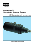
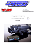
HY13-1524-001/US
Parker Product
Effective: June 2012
HTG
Transmission
Product Series
Service Procedure
Service Manual
Series Product Name
HY13-1524-001/US
General Information
WARNING
FAILURE OR IMPROPER SELECTION OR IMPROPER USE OF THE PRODUCTS AND/OR SYSTEMS
DESCRIBED HEREIN OR RELATED ITEMS CAN CAUSE DEATH, PERSONAL INJURY AND PROPERTY
DAMAGE.
This document and other information from Parker Hannifin Corporation, its subsidiaries and authorized
distributors provide product and/or system options for further investigation by users having technical expertise. It
is important that you analyze all aspects of your application and review the information concerning the product or
system in the current product catalog. Due to the variety of operating conditions and applications for these
products or systems, the user, through its own analysis and testing, is solely responsible for making the final
selection of the products and systems and assuring that all performance, safety and warning requirements of the
application are met.
The products described herein, including without limitation, product features, specifications, designs, availability
and pricing, are subject to change by Parker Hannifin Corporation and its subsidiaries at any time without notice.
© Copyright 2012 Parker Hannifin Corporation, All Rights Reserved
2
Parker Hannifin Corporation
Hydraulic Pump/Motor Division
Greeneville, Tennessee USA
Service Manual
Series Product Name
HY13-1524-001/US
General Information
Section 1
General Information
Definitions/Disclaimer
Introduction/Design Features
Troubleshooting Guide
Troubleshooting Checklist
Tools & Materials Required for Servicing
General Information
Exploded Views
Seal Kit Information
Section 2
4
5
6
7
8
9
10-11
12-13-14-15
Reseal & Repair
Disassembly & Assembly Motor Only
Disassembly
Assembly
Section 3
17- 20 Fig II
20 - 27
28 - 52
Maintenance
System Maintenance Tips
53
3
Parker Hannifin Corporation
Hydraulic Pump/Motor Division
Greeneville, Tennessee USA
Service Manual
Series Product Name
HY13-1524-001/US
General Information
WARNING
Warning describes hazards or unsafe practices which could result in severe
personal injury or death.
CAUTION
A caution describes hazards or unsafe practices which could result in personal injury or
product or property damage.
NOTE A note gives key information to make following a procedure easier or quicker.
Disclaimer
This Service Manual has been prepared by Parker Hannifin Corporation for reference and use by mechanics
who have been trained to repair and service hydraulic transmission on commercial and non-commercial
equipment applications. Parker Hannifin Corporation has exercised reasonable care and diligence to present
accurate, clear and complete information and instructions regarding the techniques and tools required for
maintaining, repairing and servicing the Parker HTG Transmission Series. Since this is a general Service
Manual, the photographs and illustrations may not look exactly like the transmission being serviced. The
procedures, therefore, must be carefully read and understood before servicing.
If inspection or testing reveals evidence of abnormal wear or damage to the HTG Transmission or if you
encounter circumstances not covered in the Manual, STOP - CONSULT THE EQUIPMENT MANUFACTURER’S
SERVICE MANUAL AND WARRANTY. DO NOT TRY TO REPAIR OR SERVICE A HTG WHICH HAS BEEN
DAMAGED OR INCLUDES ANY PART THAT SHOWS EXCESSIVE WEAR UNLESS THE DAMAGED AND
WORN PARTS ARE REPLACED WITH ORIGINAL PARKER REPLACEMENT AND SERVICE PARTS AND
THE UNIT IS RESTORED TO PARKER SPECIFICATIONS FOR THE HTG.
It is the responsibility of the mechanic performing the maintenance, repairs or service on a particular HTG
Transmission to (a) inspect the unit for abnormal wear and damage, (b) choose a repair procedure which will not
endanger his/her safety, the safety of others, the equipment or the safe operation of the HTG Transmission, and
(c) fully inspect and test the HTG Transmission and the hydraulic system to ensure that the repair or service of
the HTG Transmission has been properly performed and that the HTG Transmission and hydraulic system will
function properly.
Conversions
Inches
.020
.021
.029
.030
.111
.119
.152
.160
.296
.304
.460
.470
.500
.585
.595
.660
.675
1.058
Mm
.511
.531
.741
.760
2.81
3.02
3.86
4.06
7.52
7.72
11.68
11.94
12.70
14.86
15.11
16.76
17.15
26.87
Inches
1.060
1.295
1.297
1.396
1.398
1.620
1.622
1.983
1.985
2.120
2.122
2.233
2.235
2.483
2.485
2.500
2.88
mm
26.92
32.89
32.94
35.46
35.51
41.15
41.20
50.37
50.42
53.85
53.90
56.72
56.77
63.07
63.12
63.5
73.2
4
Parker Hannifin Corporation
Hydraulic Pump/Motor Division
Greeneville, Tennessee USA
Service Manual
Series Product Name
HY13-1524-001/US
General Information
Introduction
The three-column format used in this Service Manual will help make it easy for you to service a HTG
transmission. Column 1 illustrates the procedure with photographs, Column 2 gives a brief key for each step, and
Column 3 explains in detail the procedure you should follow. Pay special attention to the notes, cautions and
warnings.
This manual contains troubleshooting information and checklists. With them you can diagnose a hydraulic
system problem without removing the HTG Transmission, the checklists will help you to determine where the
problem may be.
Item numbers on the exploded view correspond with item numbers used throughout the Service Manual.
As you gain experience in servicing HTG Transmission, you may find that some information in this Service
Manual could be clearer and more complete. If so, let us know about it. Don’t try to second-guess the Service
Manual; if problems occur that you cannot solve, please contact our service department at 423-639-8151, or
your local Parker approved distributor. Servicing HTG Transmission should be safe and productive. Visit our web
site at www.parker.com/pumpmotor.
DESIGN FEATURES
HTG Transmission
•
•
•
High efficiency results in a cooler running system
Top housing is sturdy, lightweight aluminum, excellent at dispersing heat, resulting in
an overall cooler system
High capacity thrust bearing provides longer transmission life
Torqmotor
•
•
•
•
•
Roller vane to reduce friction and internal leakage and to maintain efficiency
A patented orbiting commutator system for less wear and longer life
A unique high-pressure shaft seal
Manifold designed to improve operating efficiency
Roller vane and sealed commutation assure high volumetric efficiency and smooth low
speed operation
5
Parker Hannifin Corporation
Hydraulic Pump/Motor Division
Greeneville, Tennessee USA
Service Manual
Series Product Name
HY13-1524-001/US
General Information
Troubleshooting Guide
NOTE
Before troubleshooting any system problem, check
service literature published by the equipment and/or
component manufacturers. Follow their instructions, if
given, for checking any component other than the
HTG Transmission.
Hydraulic Components
If you think the problem is caused by a hydraulic
component, start by checking the easy-to-reach
items.
Check all belts for cracks, hardening or other signs of
wear. Check all pulleys, fans and bolts to make sure
they are tightened to specified torque value. Look for
leaks, especially at coupling shaft and plugs.
Preparation
Make your troubleshooting easier by preparing as
follows:
If necessary replace filter. Always replace with
original Parker filter. Torque to 115 – 135 in. lbs.
• work in a clean, well-lighted place
• have proper tools and materials nearby
Visually check other components to see if they are
loosely mounted, show signs of leaks, or indicate by
other damage or wear.
• have an air pressure source.
WARNING
Since solvents are flammable, be extremely careful
when using any solvent. Even a small explosion could
cause injury or death.
Suspect Faulty Transmission
Before the transmission is disassembled for repair,
make sure all control arm adjustments and engine
speed requirements are per OEM specification. Also
make sure the parking brake is releasing fully on both
sides.
WARNING
Wear eye protection and be sure to comply with
OSHA and other maximum air pressure
requirements. Keep hands clear of fan and moving
parts can cause personal injury. Shut off engine and
let entire system cool before removing any
component.
If there is a defect in the transmission, a right to left
side performance difference should be noticeable. To
test for this condition, run the vehicle at full forward
throttle and control levers. The vehicle should track
nearly straight both on flat ground and on uphill
grades.
Preliminary Checks
Hydraulic systems are often trouble-free. Hence, the
problem an operator complains of could be caused by
something other than the hydraulic components.
Thus, once you have determined that a problem
exists, start with the easy-to-check items, such as:
• Parts damaged from impact that were not properly
repaired, or that should have been replaced
• Improper replacement parts used in previous
servicing
• Mechanical linkage problems such as binding,
broken or loose parts, or slipping belts
6
Parker Hannifin Corporation
Hydraulic Pump/Motor Division
Greeneville, Tennessee USA
Service Manual
Series Product Name
HY13-1524-001/US
General Information
Troubleshooting Checklist
Trouble
Fluid Leakage
Operates Hot
No or Low Power
Cause
1. Fitting loose, worn or
damaged
2. Seals deteriorated by
excess heat
1. Debris buildup
Remove debris
2. Cooling fan damaged
Replace fan
3. Oil level low or
contaminated
4. Excessive loading
Either fill to proper oil level or
change filter refill with new oil
Reduce vehicle load
5. Air trapped in system
Run vehicle slowly forward and then
reverse several times
1. Oil level low or
contaminated
2. Bypass valve open
Either fill to proper oil level or
change filter and refill with new oil
Turn to closed position
3. Excessive loading
Reduce vehicle load
4. Engine speed low
Adjust engine speed to correct value
5. Air trapped in system
Run vehicle slowly forward and then
reverse several times
Disassemble and inspect
6. Suspect internal
component damage
7. Pulley or belt loose
Noisy Unit
Remedy
Check & replace damaged gasket or
“O” rings. Torque to manufacturers
specifications
Replace seals by disassembling unit
Tighten to specifications
1. Oil level low or
contaminated
2. Excessive loading
Either fill to proper oil level or
change filter and refill with new oil
Reduce vehicle load
3. Excessive speed input
Adjust input speed above 1800 rpm
and below 3600 rpm
Run vehicle slowly forward and then
reverse several times
Turn to closed position
4. Air trapped in system
5. Bypass valve open
7
Parker Hannifin Corporation
Hydraulic Pump/Motor Division
Greeneville, Tennessee USA
Service Manual
Series Product Name
HY13-1524-001/US
General Information
Tools and Materials Required for Servicing
• Clean, petroleum-based solvent
• To insure maximum transmission performance and life, use a Parker recommended fluid and filter
change schedule.
At 300 hour break-in period change the oil and filter. Subsequent oil and filter change intervals depend
on the type of oil used. Always change the filter when changing the oil.
Qualified Oils
Parker GT Blend
1000 hour
Castrol Syntec 5W50 500 hour
Amsoil AW ISO 68
500 hour
Shell TTF-SB
500 hour
Other*
250 hour
Must be premium grade synthetic based engine oil with a minimum viscosity grade of 15W40.
• Emery paper
• Vise with soft jaws
• Rubber mallet
• Air-pressure source
• Arbor press
• Flat screwdriver
• Grease pencil or paint pen
• Small gear puller
• 1/4" torque wrench : 270-300 in-lbs, 100-120 in-lbs, 200-240 in-lbs, 50-70 ft-lbs, 350-400 ft-lbs,
45-55 ft-lbs
• Sockets: 3/8" drive ratchet, 5/16”, 15/16”, 9/16”, T30 Torx Bit,13mm
• Vise grip™ pliers
• Internal snap ring pliers
• Clean corrosion resistant grease. Recommended grease is Mobil Mobilith SHC® 460 or equivalent.
CAUTION
Mixing greases that have different bases can be detrimental to bearing life.
8
Parker Hannifin Corporation
Hydraulic Pump/Motor Division
Greeneville, Tennessee USA
Service Manual
Series Product Name
HY13-1524-001/US
Dimensional Data
Rear of Mower
9
Parker Hannifin Corporation
Hydraulic Pump/Motor Division
Greeneville, Tennessee USA
Service Manual
Series Product Name
HY13-1524-001/US
Dimensional Data
Exploded View - Typical
Left Hand
10
Parker Hannifin Corporation
Hydraulic Pump/Motor Division
Greeneville, Tennessee USA
Service Manual
Series Product Name
HY13-1524-001/US
Dimensional Data
Right Hand
11
Parker Hannifin Corporation
Hydraulic Pump/Motor Division
Greeneville, Tennessee USA
Service Manual
Series Product Name
HY13-1524-001/US
Seal Kit Data
SK000275
PARTS LIST – FAN KIT
ITEM
QTY
PART NUMBER
DESCRIPTION
1
1
025164
NUT
2
1
477370
FAN SPACER
3
1
420067
FAN (8.3 INCH)
1
SK000275 SHEET 3
SERVICE BULLETIN
SK000276
PARTS LIST - MOTOR KIT (240cc- Right Hand Side)
QTY
PART NUMBER
1
1
TG0240SD081HTAA
2
2
032202-116
O-RING
3
1
034005
SIDE COVER GASKET
1
SK000276 SHEET 3
SERVICE BULLETIN
SK000277
DESCRIPTION
PARTS LIST - MOTOR KIT (280cc - Right Hand Side)
ITEM
QTY
PART NUMBER
1
1
TG0280SD081HTAA
2
2
032202-116
O-RING
3
1
034005
SIDE COVER GASKET
1
SK000277 SHEET 3
SERVICE BULLETIN
SK000278
DESCRIPTION
PARTS LIST - MOTOR KIT (310cc - Right Hand Side)
ITEM
QTY
PART NUMBER
1
1
TG0310SD081HTAA
2
2
032202-116
O-RING
3
1
034005
SIDE COVER GASKET
1
SK000278 SHEET 3
SERVICE BULLETIN
SK000279
DESCRIPTION
PARTS LIST - MOTOR KIT (240cc - Left Hand Side)
ITEM
QTY
PART NUMBER
DESCRIPTION
1
1
TG0240SD080HTAA
2
2
032202-116
O-RING
3
1
034005
SIDE COVER GASKET
1
SK000279 SHEET 3
SERVICE BULLETIN
12
Parker Hannifin Corporation
Hydraulic Pump/Motor Division
Greeneville, Tennessee USA
Service Manual
Series Product Name
HY13-1524-001/US
Seal Kit Data
SK000280
PARTS LIST - MOTOR KIT (280cc - Left Hand Side)
ITEM
QTY
PART NUMBER
1
1
TG0280SD080HTAA
2
2
032202-116
O-RING
3
1
034005
SIDE COVER GASKET
1
SK000280 SHEET 3
SERVICE BULLETIN
SK000281
DESCRIPTION
PARTS LIST - MOTOR KIT (310 cc - Left Hand SIde)
ITEM
QTY
PART NUMBER
1
1
TG0310SD080HTAA
2
2
032202-116
O-RING
3
1
034005
SIDE COVER GASKET
1
Sk000281 SHEET 3
SERVICE BULLETIN
SK000282
DESCRIPTION
PARTS LIST - MOTOR KIT (Brake Kit - 5 Bolt / 2 Hole Lever)
ITEM
QTY
PART NUMBER
DESCRIPTION
1
1
040204
COTTER PIN
2
1
490164
BRAKE SHOE ASSEMBLY WITH TWO HOLE LEVER ARM
3
1
490165
5 BOLT BRAKE DRUM
4
4
020207
5/16-18 FLANGE HEAD CAP SCREWS
5
1
025113
1-20 SLOTTED NUT
1
SK000282 SHEET 3
SERVICE BULLETIN
SK000283
PARTS LIST - MOTOR KIT (Brake Kit - 4 Bolt / 2 Hole Lever)
ITEM
QTY
PART NUMBER
DESCRIPTION
1
1
040204
COTTER PIN
2
1
490164
BRAKE SHOE ASSEMBLY WITH TWO HOLE LEVER ARM
3
1
490080
4 BOLT BRAKE DRUM
4
4
020207
5/16-18 FLANGE HEAD CAP SCREWS
5
1
025113
1-20 SLOTTED NUT
1
SK000283 SHEET 3
SERVICE BULLETIN
13
Parker Hannifin Corporation
Hydraulic Pump/Motor Division
Greeneville, Tennessee USA
Service Manual
Series Product Name
HY13-1524-001/US
Seal Kit Data
SK000284
PARTS LIST - MOTOR KIT (Break Kit - 5 Bolt / 1 Hole Lever)
ITEM
QTY
PART NUMBER
DESCRIPTION
1
1
040204
COTTER PIN
2
1
490169
BRAKE SHOE ASSEMBLY WITH ONE HOLE LEVER ARM
3
1
490165
5 BOLT BRAKE DRUM
4
4
020207
5/16-18 FLANGE HEAD CAP SCREWS
5
1
025113
1-20 SLOTTED NUT
1
SK000284 SHEET 3
SERVICE BULLETIN
SK000285
PARTS LIST - MOTOR KIT (Brake Kit - 4 Bolt / 1 Hole Lever)
ITEM
QTY
PART NUMBER
DESCRIPTION
1
1
040204
COTTER PIN
2
1
490169
BRAKE SHOE ASSEMBLY WITH ONE HOLE LEVER ARM
3
1
490080
4 BOLT BRAKE DRUM
4
4
020207
5/16-18 FLANGE HEAD CAP SCREWS
5
1
025113
1-20 SLOTTED NUT
1
SK000285 SHEET 3
SERVICE BULLETIN
SK000287
PARTS LIST - SECTION SEAL KIT
ITEM
QTY
PART NUMBER
DESCRIPTION
1
1
401114
RETAINING RING
2
1
478086
DIRT AND WATER SEAL
3
1
028008
SEAL WASHER
4
2
032202-116
O-RING SEAL
5
1
034005
SIDE COVER GASKET
6
1
034004
BOTTOM COVER GASKET
7
2
032206-018
O-RING SEAL
8
1
032203-114
O-RING SEAL
1
SK000287 SHEET 3
SERVICE BULLETIN
14
Parker Hannifin Corporation
Hydraulic Pump/Motor Division
Greeneville, Tennessee USA
Service Manual
Series Product Name
HY13-1524-001/US
Seal Kit Data
SK000288
PART LIST - MOTOR SEAL KIT
1
1
478035
DIRT AND WATER SEAL
2
1
028515
BACKUP RING
3
1
029118
BACKUP WASHER
4
1
032818
SHAFT SEAL
5
3
032820
VITON SECTION O-RING
6
2
032862
SECTION O-RING
7
1
032861
SEAL RING
8
1
032202-244
OD END COVER O-RING SEAL
9
2
032202-116
MOTOR TO ENDBLOCK O-RING SEALS
10
1
034005
SIDE COVER GASKET
1
Sk000288 SHEETS 3-5
SERVICE BULLETIN
15
Parker Hannifin Corporation
Hydraulic Pump/Motor Division
Greeneville, Tennessee USA
Service Manual
Series Product Name
HY13-1524-001/US
Warning Data
Before you disassemble the HTG Transmission or any of its components, read this entire manual. It provides
important information on parts and procedures you will need to know to service the HTG Transmission unit. Be
sure that you know and understand the equipment and any hazards associated with performing these
procedures.
Thoroughly clean off all outside dirt and grass, especially from around fittings and hose connections before
disconnecting and removing the HTG Transmission. Remove rust or corrosion from the coupling shaft.
Remove belt connections immediately plug port holes and any fluid lines.
Depends on how the HTG is mounted to vehicle if the nut, brake hub and brake back plate needs to be removed
prior to the HTG removal for inspection and or repair. It is recommended by the factory to remove these items
prior to HTG as a safer practice. Refer to page 10 and 11 illustrations for removal and replace of the brake
assembly and torque specifications.
Remove the HTG Transmission from the system, drain it of fluid and take it to a clean work surface.
Remove fan from shaft prior to servicing any portion of transmission to prevent from breaking.
Clean and dry the HTG Transmission before you start to disassemble it.
As you disassemble the HTG Transmission, clean all parts, except seals, in clean, OSHA approved solvent, and
use low pressure air to blow them dry.
WARNING
Since they are oil and grease that can be flammable be extremely careful when using any solvent. Even a
small explosion or fire could cause injury or death.
WARNING
Wear eye protection and be sure to comply with OSHA and other maximum air pressure requirements.
WARNING
Never steam or use high pressure to wash hydraulic components. Do not force or abuse closely fitted
parts.
WARNING
Never attempt to tow, push or pull equipment with another vehicle. Towing will cause hydraulic
transmission further damage. If equipment needs to be moved make sure both transmission bypass valves are
open and hand push.
Keep parts separate to avoid nicks and burrs.
Discard all seals and seal rings as they are removed from the HTG Transmission unit. Replace all seal rings and
any damaged or worn parts with genuine Parker Hannifin Corporation or OEM approved service parts.
16
Parker Hannifin Corporation
Hydraulic Pump/Motor Division
Greeneville, Tennessee USA
Service Manual
Series Product Name
HY13-1524-001/US
Disassembly
Remove Transmission
unit from vehicle
NOTE: If exchanging the
hydraulic motor only
follow these next
seventeen steps:
Either plug the expansion
tube fitting or place tape
over the end of the
expansion tube fitting to
keep oil from leaking out.
Clean unit free of grass and
other debris; let dry and
place on a clean working
table.
Place an oil pan for oil
collection under the unit.
Remove filter from unit drain
oil.
If a complete tear down is
needed please go to FIG II
on page 20
Remove side cover
Remove the five screws
from the side cover and
remove cover.
Remove gasket
Remove gasket inspect for
any damage replace if
needed.
Loosen and remove four
bolts
Notice that two of the four
bolts are longer these have
to be returned in the same
position.
17
Parker Hannifin Corporation
Hydraulic Pump/Motor Division
Greeneville, Tennessee USA
Service Manual
Series Product Name
HY13-1524-001/US
Disassembly
Remove top housing from
motor end cover
Remove top housing and set
aside.
Remove the entire motor
assembly
Remove the entire motor out
from the top housing.
Replace O ring
After you remove the motor
the filter tube will be free to
remove and replace O ring.
Installing new motor
Place the two O rings on the
end cover and outside cover
O ring onto the new motor.
Install top housing onto
motor end cover
With the motor housing in a
soft jaw vice install the top
housing onto motor end
cover. Align these two
components together
pressing down on top
housing to secure the end
cover.
18
Parker Hannifin Corporation
Hydraulic Pump/Motor Division
Greeneville, Tennessee USA
Service Manual
Series Product Name
HY13-1524-001/US
Disassembly
Place the charge pump
pick up tube to the correct
bolt position replace
torque bolts
Push the charge pump tube
O ring inside of charge pump
cover. Notice that two of the
bolts are longer than other
two.
Torque each bolt to 45 – 55
ft. lbs.
Install side cover gasket
Place the side cover gasket
on top of housing align to
screw holes.
Install side cover screws
torque to specifications.
Install new filter
Fill transmission with
Parker recommended oil
Place side cover on top of
gasket. Start each five self
tapping screws half way
down. Starting at one of the
¼--20 screws torque to 100
– 200 in. lbs. repeat process
by going diagonal to the next
screw.
Hand start the filter into
threads of top housing.
Using a socket and torque
wrench torque the filter to
115 -135 in. lbs. Fill
transmission with Parker
recommended oil 96 oz.
To insure maximum
performance and life, use a
Parker recommended fluid
listed on page 8.
19
Parker Hannifin Corporation
Hydraulic Pump/Motor Division
Greeneville, Tennessee USA
Service Manual
Series Product Name
HY13-1524-001/US
Disassembly
Replace plug
Hand start hollow hex plug
Torque Hollow Hex Plug
Torque to 100 – 120 in. lbs.
FIG II
Remove the fluid filter to
completely drain unit
Place a pan for fluid
collection under the unit.
Remove the filter from the
unit allowing the fluid to
drain into the pan.
Drain oil out of unit
To help drain fluid either
remove tape or fitting to act
as a vent.
Remove fan nut
With a 15/16” socket remove
the fan / pulley nut. Inspect
nut for any thread or other
damage. If none exits nut
can be reused. Apply Loctite
™ 242 to threads of nut if to
be reused.
20
Parker Hannifin Corporation
Hydraulic Pump/Motor Division
Greeneville, Tennessee USA
Service Manual
Series Product Name
HY13-1524-001/US
Disassembly
Remove four tab washer
Remove the fan
Check for any damage due
to normal wear. If none exist
fan can be reused.
Remove pulley
May require using (Posi
Lock Model 204) puller or a
bearing puller to take off
pulley.
CAUTION: Use caution not
to bend or damage pulley
Remove RTN assembly if
equipped
Use a ¼” allen wrench to
remove both allen head
screws.
Remove side cover
Remove the five screws
from the side plate and
remove plate.
21
Parker Hannifin Corporation
Hydraulic Pump/Motor Division
Greeneville, Tennessee USA
Service Manual
Series Product Name
HY13-1524-001/US
Disassembly
Remove gasket
Remove gasket inspect for
any damage replace if
needed.
Loosen and remove four
bolts
Remove the entire motor
assembly
Remove the entire motor out
from the top housing.
Remove bottom cover
Remove the ten (1/4-20)
screws from bottom cover.
Plug and washer
If plug was removed to drain
the oil inspect the washer
between pan and plug.
Replace washer if
necessary. Torque plug to
50-75 in lbs.
22
Parker Hannifin Corporation
Hydraulic Pump/Motor Division
Greeneville, Tennessee USA
Service Manual
Series Product Name
HY13-1524-001/US
Disassembly
Remove charge pump pick Careful not to bend tube.
Check O ring for any
up tube and O-ring
damage replace if needed.
Remove two charge pump
cover bolts
Remove charge pump
cover
Remove and inspect the
inside of charge pump cover
for any scoring replace if
necessary.
Remove charge pump
rotor set
Remove both the charge
pump rotor and stator.
Inspect for any damage
either on the tips of rotor or
stator lobes. Replace if
necessary.
Remove bypass valve clip
Using a flat head screw
driver push clip upward to
release.
23
Parker Hannifin Corporation
Hydraulic Pump/Motor Division
Greeneville, Tennessee USA
Service Manual
Series Product Name
HY13-1524-001/US
Disassembly
Remove bypass lever
Pull bypass lever away from
stem.
Remove bypass
Pull bypass out of top
housing.
Remove four end block
screws
Remove the four end block
screws notice that two of
four bolts are longer than the
other. Inspect the threads on
each bolt.
Remove end block
Take out the entire end
block. Notice port plate may
stick to end block face.
Caution: While taking out
end block may require
holding down on the
barrel to separate from
port plate
Remove valve cap
Remove valve cap from end
block.
24
Parker Hannifin Corporation
Hydraulic Pump/Motor Division
Greeneville, Tennessee USA
Service Manual
Series Product Name
HY13-1524-001/US
Disassembly
Remove spring and shock
valve
NOTE: Keep the shock
valve in the same port as
removed.
Remove port plate and
inspect
Note brass side of port
plate faces rotating group
Remove rotating group
with pistons
Inspect each piston one at
a time to keep original
piston and spring to barrel
position
Turn end block to side and
remove spring and shock
valve.
Repeat other side keeping
the shock valves tagged it is
important to keep these two
valves in the same hole
location.
Inspect for any damage to
the port plate. If the brass
side of port plate has heavy
scoring on face replace with
new port plate.
Place your fingers around
each piston to ensure they
do not fall out of barrel.
Pistons have to stay in
original location of the barrel.
Check surface of rotation
group and sides of pistons
for excessive wear, indicated
by scoring or scratch marks.
Remove pistons, springs
check bores for signs of
scoring.
Remove central spring
25
Parker Hannifin Corporation
Hydraulic Pump/Motor Division
Greeneville, Tennessee USA
Service Manual
Series Product Name
HY13-1524-001/US
Disassembly
Remove top washer (.250”
thick)
Remove top washer inspect
for any pitting or galling to
either side of top washer.
Remove thrust bearing
Remove thrust bearing
inspect bearing rollers for
any signs of pitting or galling
to rollers.
Remove bottom washer
(.125” thick)
Remove and inspect bottom
thrust washer for any pitting
and galling of either side of
washer.
Remove swash block
Remove swash block.
Inspect top and bottom
surfaces for excessive wear.
Remove control block
Remove the square control
block.
26
Parker Hannifin Corporation
Hydraulic Pump/Motor Division
Greeneville, Tennessee USA
Service Manual
Series Product Name
HY13-1524-001/US
Disassembly
Remove both cradle
bushings
Remove and inspect both
cradle bushings for
excessive wear, pitting or
scoring. Light visual wear of
coating is allowed.
Remove shaft seal snap
ring
With internal snap ring pliers
remove snap ring.
Remove pump shaft and
bearing assembly
Tap top of shaft with a
rubber mallet to loosen.
Keep assembly as level as
possible not to damage shaft
and housing.
Shaft and bearing
assembly
When shaft is free from
housing assembly shaft seal
will also be removed.
Remove trunnion arm
Push trunnion arm in and
remove.
27
Parker Hannifin Corporation
Hydraulic Pump/Motor Division
Greeneville, Tennessee USA
Service Manual
Series Product Name
HY13-1524-001/US
Disassembly
Remove trunnion arm seal
NOTE: Make sure not to
score the edges of housing
while removing trunnion arm
seal.
If necessary, remove
trunnion arm seal. Position
the flat edge of screw driver
under the lip of seal and lift
outward.
28
Parker Hannifin Corporation
Hydraulic Pump/Motor Division
Greeneville, Tennessee USA
Service Manual
Series Product Name
HY13-1524-001/US
Assembly
Install trunnion arm seal
Starting with the top housing
polish out any burrs if
needed with emery paper.
Clean seal area with a lint
free cloth.
To assist alignment of seal
install trunnion arm
Place trunnion seal over
arm
Lightly apply synthetic oil to
trunnion arm seal slide over
the trunnion arm with the
seal lip towards housing.
Seat trunnion arm seal
With a 5/8” deep well socket
gently tap socket with rubber
hammer driving seal into
place.
Trunnion arm seal
Trunnion seal should be
below top housing face.
29
Parker Hannifin Corporation
Hydraulic Pump/Motor Division
Greeneville, Tennessee USA
Service Manual
Series Product Name
HY13-1524-001/US
Assembly
Install pump shaft and
bearing assembly into top
housing
Place the extended shaft
through hole.
Seat shaft bearing to
bottom of top housing
Push shaft and bearing
assembly to the bottom of
the top housing.
Install pump seal
Place seal over output shaft
avoid any sharp edges while
installing seal over the pump
shaft.
Aid of socket
Place socket on top of
charge pump seal.
30
Parker Hannifin Corporation
Hydraulic Pump/Motor Division
Greeneville, Tennessee USA
Service Manual
Series Product Name
HY13-1524-001/US
Assembly
Seat charge pump seal
Lightly tap socket with a
rubber mallet until seal is
below snap ring groove.
Install snap ring
Use internal snap ring pliers
and insert snap ring into
groove of top housing.
Install the two cradle
bushing
Place each cradle bushing
pin hole to inner top housing
pin.
Do not stake pins.
Both cradle bushing in
place
Apply synthetic oil on top of
each cradle bushing.
31
Parker Hannifin Corporation
Hydraulic Pump/Motor Division
Greeneville, Tennessee USA
Service Manual
Series Product Name
HY13-1524-001/US
Assembly
Trunnion arm
Push the trunnion flush to
inner top housing.
Install control block
Install control block onto
trunnion arm inside of top
housing.
Install swash block
Install swash block
subassembly onto cradle
bearings in top housing.
Align swash block with
control block using a small
screwdriver.
Align swash block to the
control block
Verify that swash block
moves freely back and forth
on bushing without binding
or dragging.
Apply oil into swash block
Apply synthetic oil prior to
installing thin washer into
swash block.
32
Parker Hannifin Corporation
Hydraulic Pump/Motor Division
Greeneville, Tennessee USA
Service Manual
Series Product Name
HY13-1524-001/US
Assembly
Install thrust washer
Install thin (.125”) thrust
washer into swash block.
Install thrust bearing
Install thrust bearing on top
of thrust washer.
Install top washer
Install thick (.250”) thrust
washer into swash block.
Apply synthetic oil to the top
washer.
Central spring
Place central spring onto
pump shaft.
Rotating group assembly
By holding all pistons tight in
place turn upside down and
position pistons towards top
of thrust washer.
33
Parker Hannifin Corporation
Hydraulic Pump/Motor Division
Greeneville, Tennessee USA
Service Manual
Series Product Name
HY13-1524-001/US
Assembly
Install rotating group over
the charge pump shaft
Flip rotating group over and
onto thrust washer. Do not
release pistons until
properly seated onto top
washer. Press barrel down
to feel piston and springs
are compressing freely.
Oil top of barrel assembly
Apply synthetic oil to top of
barrel assembly face
End Block
Prepare end block for sub
assembly.
Inspect face of end block to
ensure no scratches are inbetween kidney ports and
dowel pins are in place.
Install shock valve and
spring
NOTE: Keep the shock
valve in the same port as
removed.
Install valve cap
Turn end block to side insert
the shock valve bullet noise
first with the spring on the
back side of shock valve.
Capture the spring into the
valve cap hand start threads
into end block assembly.
34
Parker Hannifin Corporation
Hydraulic Pump/Motor Division
Greeneville, Tennessee USA
Service Manual
Series Product Name
HY13-1524-001/US
Assembly
Repeat shock valve
installation opposite side
Install shock valve and
spring
Turn end block to side and
insert the shock valve bullet
nose first with the spring on
the back side of shock
valve.
Install valve cap
Capture the spring into the
valve cap hand start threads
into end block assembly.
Torque valve cap
Torque both caps to
40 – 45 ft. lbs.
Make sure end block is
free of any debris apply oil
to face of end block
Apply synthetic oil on the
face of end block. Oil will
allow the port plate to stick
to the end block
35
Parker Hannifin Corporation
Hydraulic Pump/Motor Division
Greeneville, Tennessee USA
Service Manual
Series Product Name
HY13-1524-001/US
Assembly
Port plate
Place the port plate onto the
end block assemble bronze
side facing up. Align port
plate to both dowel pins.
Apply Oil onto port plate
Apply synthetic oil on face of
port plate spread over the
entire plate.
Placing end block into top
housing
While holding the port plate
in place turn the end block
over and place into proper
area in the top housing.
Align end block to bolt
holes
Handle careful not to
damage splines of charge
pump shaft and port plate
stays in position.
End block aligned to top
housing
36
Parker Hannifin Corporation
Hydraulic Pump/Motor Division
Greeneville, Tennessee USA
Service Manual
Series Product Name
HY13-1524-001/US
Assembly
Insert and hand start four
bolts
Insert four bolts 3/8-16 X 2”
Torque each bolt
Torque each (3/8-16) bolt by
going diagonal to 550 - 660
in. lbs.
Apply oil to face of
endblock
Apply a small amount of
synthetic oil to the face of
the end block.
Install rotor
Place the rotor onto pump
shaft splines.
Install stator
Place the outside stator onto
face of end block.
37
Parker Hannifin Corporation
Hydraulic Pump/Motor Division
Greeneville, Tennessee USA
Service Manual
Series Product Name
HY13-1524-001/US
Assembly
Charge pump cover
Place the charge pump
cover over the charge pump
rotor and stator.
Align bolt holes to end
block
Align the charge pump cover
holes to the end block.
Start two bolts
Hand start the two bolts of
the charge pump cover to
end block.
Torque bolts
Torque both bolts by going
diagonal to 90 - 110 in. lbs.
Bypass relief valve
Place bypass relief valve
into end block.
38
Parker Hannifin Corporation
Hydraulic Pump/Motor Division
Greeneville, Tennessee USA
Service Manual
Series Product Name
HY13-1524-001/US
Assembly
Bypass stem
Place the bypass stem into
top housing hole and align
with bypass valve.
Bypass valve clip
assembly
Push the retaining clip on
stem of bypass valve
groove.
Bypass lever
Place the bypass lever into
slot of the valve push until
lever arm snaps into place.
Position lever arm to closed
bypass valve.
Charge pump pick up tube
Place O-ring onto the end of
charge pump pick up tube.
Lightly oil the O-ring with
synthetic oil.
Install tube into charge
pump cover
Push the charge pump tube
inside of charge pump
cover.
39
Parker Hannifin Corporation
Hydraulic Pump/Motor Division
Greeneville, Tennessee USA
Service Manual
Series Product Name
HY13-1524-001/US
Assembly
Be sure the O-ring does not
get pinched and goes up
inside of receiver stem of
charge pump cover.
Notice alignment tab on
housing this is used to align
or clock the end cover per
model code.
View of picture alignment tab
is at 12:00 o’clock position.
View of picture alignment tab
is at 12:00 o’clock position.
40
Parker Hannifin Corporation
Hydraulic Pump/Motor Division
Greeneville, Tennessee USA
Service Manual
Series Product Name
HY13-1524-001/US
Assembly
Motor Assembly
Place motor housing in
soft jawed vice
Warning: If the torqmotor
is not firmly held in the
vise, it could be dislodged
during the service
procedures, causing
injury.
Place front of housing nose
pointed down and the vise
jaws clamping firmly on the
sides of the housing.
Notice alignment tab on
housing this is used to align
or clock the end cover per
model code.
With a clean housing pull
the two thrust washers with
the bearing in the middle up
on edge as shown in picture.
Back up ring
Housing requires
assembling a new back up
ring, back up washer and
new shaft seal.
Back up washer
Place the thicker back up
washer either side down into
housing past the washer
bearing package. Back up
washer will lay flat into
groove of housing seal
cavity.
Next put the thin flat washer
either side down into
housing laying on top of the
back up ring.
41
Parker Hannifin Corporation
Hydraulic Pump/Motor Division
Greeneville, Tennessee USA
Service Manual
Series Product Name
HY13-1524-001/US
Assembly
Install shaft seal
Place the flat side of shaft
seal towards the flat washer
and the lip of seal towards
end cover. Use your fingers
press shaft seal firmly into
housing seal groove until it
makes contact to flat
washer.
Lay the washer bearing
package flat
Make sure the thrust bearing
stays in the middle of the
two washers. Lay the
washer bearing package flat
to housing face.
Apply oil on the shaft
Apply synthetic oil to help
shaft passing through lip of
shaft seal package.
Insert shaft into housing
Slightly rotate shaft while
pushing down so that it
passes through seal
package and bottoms out to
the top thrust washer.
Top of output shaft
Top of the shaft should be
even with the radial bearing
face.
42
Parker Hannifin Corporation
Hydraulic Pump/Motor Division
Greeneville, Tennessee USA
Service Manual
Series Product Name
HY13-1524-001/US
Assembly
Install thrust bearing
Install thrust bearing onto
the end of coupling shaft.
Install drive link
Install drive link long splined
end down into the coupling
shaft. Engage drive link
splines until they mesh with
the internal coupling shaft
splines.
Install housing face o-ring
Apply small amount of clean
grease to a new section seal
ring and assemble it into the
seal ring groove of the
housing face.
Assemble wear plate
Place wear plate over drive
link.
Alignment of wear plate to
housing bolt holes
Align wear plate holes to the
housing bolt holes.
43
Parker Hannifin Corporation
Hydraulic Pump/Motor Division
Greeneville, Tennessee USA
Service Manual
Series Product Name
HY13-1524-001/US
Assembly
Assemble seal ring
Install the assembled rotor
set
Note: Rotor counterbore
side must be down against
wear plate for drive link
clearance and to maintain
the rotor-drive link spline
contact.
Apply small amount of clean
grease to new seal ring and
assemble it into the seal ring
groove of the rotor set.
Install the assembled rotor
set with rotor counterbore
and seal ring side facing
down onto wear plate.
Alignment of rotor set to
housing bolt holes
Turn the assembly so that
the holes match up with the
bolt holes of housing.
Install rotor thrust washer
Place thrust washer on the
tip of drive link and into
groove of rotor.
Washer installed
Washer will fit flush to top of
rotor.
44
Parker Hannifin Corporation
Hydraulic Pump/Motor Division
Greeneville, Tennessee USA
Service Manual
Series Product Name
HY13-1524-001/US
Assembly
Assemble square cut seal
ring in manifold
The manifold is made up
of several plates bonded
together permanently to
form an integral
component.
Apply clean grease to a new
square cut seal ring and
assemble it in the seal ring
groove of rotor set side of
the manifold.
The manifold surface that
must contact the rotor set
has a series of irregular
shaped cavities on the
largest circumference and
circle around the inside
diameter.
Face shown goes towards
the rotor set.
Assemble manifold
Assemble the manifold over
the drive link and onto the
rotor set.
Face shown towards
commutator set.
Assemble O-ring seal
Apply clean grease to a new
seal ring and assemble it in
the seal ring groove of
manifold top side.
Assemble seal and
commutator
Assemble new seal ring flat
side up into commutator.
Notice commutator seal is
formed in a “V” shape the
flat side faces towards end
cover.
45
Parker Hannifin Corporation
Hydraulic Pump/Motor Division
Greeneville, Tennessee USA
Service Manual
Series Product Name
HY13-1524-001/US
Assembly
Place commutator over
drive link onto manifold
Place commutator over the
end of drive link onto
manifold with the seal ring
face side up.
Assemble commutator
ring
Place commutator ring on
top of manifold and align the
holes up with the bolt holes
of housing.
The commutator and
commutator ring are a
matched set
Assemble seal ring and
end cover
Apply clean grease to a new
seal ring and assemble it in
the seal ring groove of end
cover.
Install the three end cover
bolts
Picture shown is for a
reverse time (RH) motor.
Install the three end cover
bolts
Picture shown is for a
standard timed (LH) motor.
46
Parker Hannifin Corporation
Hydraulic Pump/Motor Division
Greeneville, Tennessee USA
Service Manual
Series Product Name
HY13-1524-001/US
Assembly
Torque bolts to
specifications
Install both end cover
O-rings
Apply clean grease onto
each O-ring and place in the
groove area of the end
cover.
End cover O-ring
Place O-ring over the end
cover and into groove.
Install top housing onto
motor end cover
With the motor still in the
vise place the top housing
assembly onto the end
cover of the motor.
Align the top housing to
the two O-rings in the end
cover
Align these two components
together pressing down on
the top housing to secure
the end cover O-ring fits
inside of top housing cavity.
47
Parker Hannifin Corporation
Hydraulic Pump/Motor Division
Greeneville, Tennessee USA
Service Manual
Series Product Name
HY13-1524-001/US
Assembly
Place flat washer under
head of each bolt
Starting with two bolts
measuring 6.125” place
washer under head of each
bolt.
Refer to picture for bolt
location
Hand start each bolt to
ensure you do not cross
thread. Refer to picture for
location of bolt.
Repeat step for the second
bolt that measures 6.125”
long.
Refer to picture for bolt
location
Place washer on the two
remaining bolts that
measure 6.625” long.
Hand start each bolt to
ensure you do not cross
thread. Refer to picture for
location of bolt.
48
Parker Hannifin Corporation
Hydraulic Pump/Motor Division
Greeneville, Tennessee USA
Service Manual
Series Product Name
HY13-1524-001/US
Assembly
Torque each bolt to
specification
Torque each bolt to 45-55 ft.
lbs. by going diagonal from
each bolt.
Install side cover gasket
Place the side cover gasket
on top housing.
Install side cover
Place the side cover on top
of gasket and align the
screw holes.
Install side cover screws
Start one of the self tapping
screws half way down.
Install side cover screws
Start the second self tapping
screw again only half way
down.
49
Parker Hannifin Corporation
Hydraulic Pump/Motor Division
Greeneville, Tennessee USA
Service Manual
Series Product Name
HY13-1524-001/US
Assembly
Install side cover screws
Repeat process until each
screw has been started half
way down.
Torque side cover screws
Starting at one of the (1/420) screws torque to 100 –
120 in. lbs. repeat process
by following the marked
number on the side cover
plate.
Side cover is marked in
order how each screw is
torque.
Install filter
Hand start the filter into the
top housing hand tight.
Torque filter
Using a socket and torque
wrench torque the filter to
115 -135 in. lbs. Use caution
do not over torque causing
hex plug damage.
CAUTION
Do not over torque
Install bottom gasket
Place the bottom gasket
according to bolt pattern.
Aid of alignment pins
If available use three
alignment roll pins that fit
the screw holes to help keep
the gasket from moving out
of place.
50
Parker Hannifin Corporation
Hydraulic Pump/Motor Division
Greeneville, Tennessee USA
Service Manual
Series Product Name
HY13-1524-001/US
Assembly
Install bottom cover
Place the bottom cover over
gasket. Use alignment pins
to keep cover from shifting.
Start self tapping screws
Start one of the self tapping
screws half way down.
Start each one of the self
tapping screws
Repeat process until each
screw has been started half
way down. Take out the
alignment pins and replace
with screw.
Torque bottom screws
Starting at the number one
screw torque to 100 – 120
in. lbs. repeat by following
the marked number on the
bottom cover until all screws
have been properly torque.
Bottom cover is marked in
order how each screw is
torque.
Plug and washer
If plug and washer was
removed during
disassembly inspect
washer. Hand start threads
and torque plug 50-75 in lbs.
51
Parker Hannifin Corporation
Hydraulic Pump/Motor Division
Greeneville, Tennessee USA
Service Manual
Series Product Name
HY13-1524-001/US
Assembly
Install RTN if equipped
If the original unit had a
RTN and was removed
reinstall RTN onto trunnion
arm shaft. Hand start the
two socket head cap screws
and torque to 90 – 110 in
lbs.
Install pulley, fan, lock
washer and nut
Place the pulley onto pump
shaft.
Install fan
Place the fan with the tabs
pointing up onto the pump
shaft.
Install four tab washer
Place the four tab washer
onto fan with the tabs inbetween the fan tabs.
Install nut
Apply Loctite ™ 242 to
threads of nut. Torque nut to
86 – 70 ft lbs.
52
Parker Hannifin Corporation
Hydraulic Pump/Motor Division
Greeneville, Tennessee USA
Service Manual
Series Product Name
HY13-1524-001/US
Assembly
Install expansion tank
barb fitting
Hand start the expansion
tank barb fitting and torque
to 200 – 240 in. lbs.
Remove tape and fill with
synthetic oil – 140 cc to
completely fill each unit.
To insure maximum
transmission performance
use Parker recommended
fluid listed on page 8.
Fill transmission to the
expansion tank fitting with
96 oz of oil.
Replace plug
Hand start hollow hex plug.
Torque hollow hex plug
Torque hollow hex plug to
100 – 120 in. lbs.
Finished Assembly
Brake pads, hub and nut will
have to be assembled after
HTG has been installed on
vehicle frame.
53
Parker Hannifin Corporation
Hydraulic Pump/Motor Division
Greeneville, Tennessee USA
Service Manual
Series Product Name
HY13-1524-001/US
Maintenance
System Maintenance Tips
•
•
•
•
•
•
•
Adjust fluid level in reservoir as necessary.
Encourage all operators to report any malfunction or accident that may have damaged the hydraulic
system or component.
Do not attempt to weld any broken HTG Transmission component. Replace any component with original
Parker parts.
Do not cold straighten, hot straighten, or bend any Torpact Transmission part.
Prevent dirt or other foreign matter from entering the hydraulic system. Clean the area around the filler
caps before checking oil level.
Investigate and correct any external leak in the hydraulic system, no matter how minor the leak.
Comply with Parker specifications for cleaning or replacing the filter.
CAUTION
Do not weld, braze, solder or in any way alter any HTG Transmission component.
Maximum operating pressure must not exceed recommended HTG Transmission
CAUTION
pressure capacity.
Always carefully inspect any system component that may have been struck or damaged
CAUTION
during operation or in an accident. Replace any component that is damaged or that is questionable.
CAUTION
unit internally.
Do not force any coupling onto the HTG pump coupling shaft as this could damage the
Do not mix oil types. Any mixture or any unapproved oil could deteriorate the seals.
CAUTION
Maintain the proper fluid level in the reservoir. When changing fluid, completely drain old oil from the system. It is
suggested also that you flush the system with clean oil.
Parker Pump/Motor HPM Operation extends close technical cooperation and assistance. If problems occur
which you cannot solve, please contact our service department at (423) 639-8151, or your local Parker approved
distributor.
54
Parker Hannifin Corporation
Hydraulic Pump/Motor Division
Greeneville, Tennessee USA
Service Manual
Series Product Name
HY13-1524-001/US
Notes
55
Parker Hannifin Corporation
Hydraulic Pump/Motor Division
Greeneville, Tennessee USA
Parker Hannifin Corporation
Hydraulic Pump/Motor Division
2745 Snapps Ferry Road
Greeneville, TN 37745 USA
Tel.
(423) 639-8151
FAX
(423) 787-2418
www.parker.com/pumpmotor