1
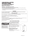
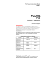
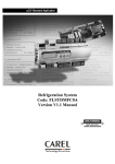
Service Manual SM1532 Parker Motors Effective: January 1, 1996 Low Speed High Torque Hydraulic Motors 716 Series Definitions WARNING: ! CAUTION: ! NOTE: A WARNING refers to procedures that must be followed for the safety of the equipment operator and the person inspecting or repairing the motor. A CAUTION refers to a mandatory procedure which avoids damage to the motor or other system components. A NOTE provides key information to make a procedure easier or quicker to complete. ! WARNING FAILURE OR IMPROPER SELECTION OR IMPROPER USE OF THE PRODUCTS AND/OR SYSTEMS DESCRIBED HEREIN OR RELATED ITEMS CAN CAUSE DEATH, PERSONAL INJURY, AND PROPERTY DAMAGE. This document and other information from Parker Hannifin Corp., its subsidiaries and authorized distributors provide product and/or system options for further investigation by users having technical expertise. It is important that you analyze all aspects of your application and review the information concerning the product or system in the current product catalog. Due to the variety of operating conditions and applications for these products or systems, the user, through its own analysis and testing, is solely responsible for making the final selection of the products and systems and assuring that all performance, safety and warning requirements of the application are met. The products described herein, including without limitation, product features, specifications, designs, availability, and pricing are subject to change by Parker Hannifin Corp. and its subsidiaries at any time without notice. 2 Parker Hannifin Corp. Hydraulic Pump/Motor Div. Greeneville, TN 37745 USA Parker Hannifin Corporation Hydraulic Pump/Motor Division 2745 Snapps Ferry Road Greeneville, TN 37745 USA Tel. (423) 639-8151 FAX (423) 787-2418 DG 6/96 7500 CONTENTS Section 1 General Information Page Definitions ............................................................................. Inside Front Cover Introduction ...................................................................................................... 2 Troubleshooting Guide .................................................................................... 3 Troubleshooting Check List ............................................................................. 4 Tools and Material Required for Servicing & Seal Kit Components .................. 5 Service Parts List ............................................................................................. 6 Exploded Assembly View .............................................................................. 7-9 Section 2 Repair Disassembly & Inspection ......................................................................... 10-15 Assembly .................................................................................................. 16-21 Solenoid Assembly ......................................................................................... 22 Final Checks ................................................................................................... 23 Section 3 Maintenence Hydraulic Fluids .............................................................................................. 23 Filtration, Operating Temperature ................................................................... 23 Tips for Maintaining the system ...................................................................... 24 Parker Hannifin Corp. Hydraulic Pump/Motor Div. Greeneville, TN 37745 USA 1 Introduction Service Manual for Series 716 Two Speed High Torque Motor This service manual has one purpose: to guide you in maintaining, troubleshooting, and servicing the 716 Two Speed High Torque Motor. These motors provide long life while operating with low radial side loads. Read the trouble shooting information to eliminate non-hydraulic causes and hydraulic system problems. The check list identifies hydraulic system and possible motor component problems. The two column format of the Disassembly and Inspection, and Assembly sections make it easier to conduct major work on the motor. Column one explains the procedure in detail. Column two illustrates this procedure with photographs. Read all material carefully and pay special attention to the notes, cautions, and warnings. The component part names and item numbers assigned on the exploded assembly views corresponds with names and item numbers (in parentheses) used in the disassembly and assembly procedures. Service part number charts display exploded view item numbers and part numbers. Obtain service parts from the Original Equipment Manufacturer or your local Parker distributor. We welcome suggestions to make this manual clearer or more complete. If you are stuck, contact Parker Hannifin Corp. at the Hydraulic Pump/Motor Division. Don’t second guess the manual. Following this safe and productive procedure results in restoring the reliable long-life operation engineered into the motor. 2 Parker Hannifin Corp. Hydraulic Pump/Motor Div. Greeneville, TN 37745 USA Troubleshooting Guide NOTE: Before troubleshooting any system problem, check service literature published by the equipment and/or component manufacturers. Follow their instructions, if given, for checking any component other than the motor unit. Preparation Preliminary Checks Make your troubleshooting easier by preparing as follows: Hydraulic systems are often trouble free. Therefore check the following easy to check items first, such as: • Work in a clean, well lighted area. • Have proper tools and materials nearby. • • Parts damaged from impact that were not properly repaired, or that should have been replaced. Have an adequate supply of clean petroleum - based solvent. • Improper replacement parts used in previous servicing. • Prior to any motor disassembly, plug the open ports and case drain. • • Clean all dirt from the outside of the motor. Mechanical linkage problems such as binding, broken parts or chain , loose parts, or slipping belts. • Prior to assembly lightly oil all seals, rollers, rolls and the threaded bolt ends. Hydraulic Components WARNING: Since solvents are flammable, be extremely careful when using any solvent, even a small explosion or ! fire could cause injury or death. WARNING: Wear eye protection and comply with OSHA and other maximum air pressure requirements. ! If the motor has low speed or torque, look at the check list on the next page first. Since these motors maintain volumetric and torque efficiencies during their useful life, the problem is usually elsewhere in the hydraulic system. However, there are hydraulic system problems which can drastically reduce the long life designed into these motors. Three key areas to check are: • Temperature: Do not exceed 180°F. • Fluid: Viscosity at the maximum temperature must exceed 50 ssu. • Filtration: A Beta 25 ratio of at least 2. Parker Hannifin Corp. Hydraulic Pump/Motor Div. Greeneville, TN 37745 USA 3 Troubleshooting Checklist 7URXEOH &DXVH 5HPHG\ 2LOOHDNDJH +RVHILWWLQJVORRVH ZRUQRUGDPDJHG &KHFNUHSODFHGDPDJHG¦2§5LQJV 7RUTXHWRPDQXIDFWXUHUVVSHFLILFDWLRQV 0RWRUVHFWLRQVHDOULQJV GHWHULRUDWHGE\H[FHVVKHDW 5HSODFHRLOVHDOULQJV&RUUHFWKHDW SUREOHP 7LHEROWORRVH ,IEROWVDUHORRVHEHFDXVHRIH[FHVVLYHSUHV VXUHVDVLQGLFDWHGE\PRVWRUDOOEHLQJORRVH UHSODFHEROWVDGYLVHFXVWRPHUWRFRUUHFWWKH SUHVVXUHUHJXODWLRQ %URNHQWLHEROWV 5HSODFHEROWV ,QWHUQDOVKDIWVHDOZRUQRU GDPDJHG 5HSODFHVHDO :RUQVKDIWDQGLQWHUQDOVHDO 5HSODFHVKDIWDQGVHDO /DFNRIVXIILFLHQWRLOVXSSO\ D &KHFNIRUIDXOW\UHOLHIYDOYHDQGDGMXVWRU UHSODFHDVUHTXLUHG E &KHFNIRUDQGUHSDLUZRUQSXPS F &KHFNIRUDQGXVHFRUUHFWRLOIRUWHPSHUDW XUHRIRSHUDWLRQ&KHFNUHVHUYRLUIOXLG OHYHO +LJKLQWHUQDOPRWRUOHDNDJH 5HSODFHZRUQ,*5VHW ([FHVVLYHKHDW /RFDWHH[FHVVLYHKHDWVRXUFHXVXDOO\DUHVWULF WLRQRUODFNRIDQRLOFRROHULQWKHV\VWHPDQG FRUUHFWWKHFRQGLWLRQ 6LJQLILFDQWORVVRI VSHHGXQGHUORDG /RZPHFKDQLFDO HIILFLHQF\RUXQGXH KLJKSUHVVXUH UHTXLUHGWR RSHUDWHPRWRU /LQHEORFNDJH /RFDWHEORFNDJHVRXUFHDQGUHSDLURUUHSODFH ,QWHUQDOLQWHUIHUHQFH 'LVDVVHPEOHPRWRULGHQWLI\DQGUHPHG\FDXVH ([FHVVLYHELQGLQJRU ORDGLQJLQV\VWHPH[WHUQDO WRPRWRUXQLW /RFDWHVRXUFHDQGHOLPLQDWHFDXVH /DFNRISUHVVXUH /RZIORZRXWSXWRISXPS 5HSDLURUUHSODFHZRUQSXPS 5HOLHIYDOYHVHWLQFRUUHFWO\ RUQRWFORVLQJFRPSOHWHO\ 5HVHWUHOLHIORRNIRUFRQWDPLQDWLRQ RUUHSODFH CAUTION: ! 4 Seals in the system will shrink, harden or crack if fluid temperatures exceed 180°F (82.2°C), resulting in loss of ability to seal. Parker Hannifin Corp. Hydraulic Pump/Motor Div. Greeneville, TN 37745 USA Service Tools & Materials, Seal Kit Tools and Materials Required to Service the 716 Series Seal Kit • Clean, petroleum-based solvent • Emery paper • Vise with soft jaws • Air pressure source • Screwdriver • Tape • Breaker bar or impact wrench • Torque wrench 50 ft. lbs • Socket 1/2 inch • 1/4 inch Allen wrench • Adjustable crescent wrench or hose fitting wrenches Seal Kit-Complete: 2550 Includes; P/N 1046 1141 2332 032841 1156 Qty 6 1 1 5 1 Description Body O-Rings Dust Seal High Pressure Seal Solenoid Block O-Rings Bearing Parker Hannifin Corp. Hydraulic Pump/Motor Div. Greeneville, TN 37745 USA 5 716 Series Service Parts List Item # Qty Part Number Description 1 8 See Below Bolts 2 1 M110C-6 4 Dowel End Cover (standard) 3 6 1046 O-Rings 4 1 See Below IGRTM Set, Rear (2904-X) 5 2 1660 Clip 6 1 See Below Shaft 7 2 1865 Commutator Plate 8 4 1021 Check Ball 9 1 PA-2534 PA-2535 PA-3106 PA-3111 PA-2817 10 1 1 PA-2532-2 (1/4-19 BSPP) PA-2532-1 (7/16-20 O-Ring) Front Bearing Housing/Flange 11 1 1 1825 (open center) 2792 (closed center) Valve 12 2 75013-10 Plug, Spool Port 13 1 1826 Spring 14 1 1156 Bearing 15 4 1320 Check Balls-Solenoid Block 16 5 032841 O-Rings-Solenoid Block 17 1 See Below IGRTM Set, Front (2917-X) 18 1 1824 (with manual override) 2891 (without manual override) Solenoid 19 2 021442 Bolt, Hex 20 1 1141 Seal, Dust 21 1 2332 Seal, High Pressure 25 1 1823 Solenoid Block (7/8-14 O-Ring, Pilot Act.) (7/8-14 O-Ring, Solenoid) (BSPP, Pilot Act.) (BSPP, Solenoid) (Manifold, Pilot Act.) Center Block Motor Disp. Item 6 Shaft Item 17 IGRTM Set Item 4 IGRTM Set Item 1 Hex Bolt 3.6/7.2 5.4/10.8 7.1/14.2 8.8/17.6 10.6/21.2 12.9/25.8 2216-072 2216-108 2216-142 2216-176 2216-212 2216-258 2917-1 2917-2 2917-3 2917-4 2917-5 2917-6 2904-1 2904-2 2904-3 2904-4 2904-5 2904-6 021363 021428 021356 021306 021382 021437 6 Parker Hannifin Corp. Hydraulic Pump/Motor Div. Greeneville, TN 37745 USA 716 Exploded View - Typical Flange End 20 1 21 3 14 17 10 Locating Ring w/Rollers Outer 3 Inner w/Rolls Valve Plate 8 6 Item No. Description 1 10 3 17 6 7 8 9 12 20 21 Bolt, Hex Front Bearing Housing/Flange O-Ring IGRTM Set Shaft Commutator Plate Check Ball Center Block Plug, Spool Port Seal, Dust Seal, High Pressure 7 9 3 12 Parker Hannifin Corp. Hydraulic Pump/Motor Div. Greeneville, TN 37745 USA 7 716 Series Exploded View - Typical Cover End 1 3 2 4 5 5 6 7 Item No. Description 1 2 3 4 5 6 7 8 9 12 Bolt, Hex Cover O-Ring IGRTM Set Clip Shaft Commutator Plate Check Ball Center Block Plug, Spool Port 8 3 9 3 12 8 Parker Hannifin Corp. Hydraulic Pump/Motor Div. Greeneville, TN 37745 USA 716 Series Exploded View - Typical Optional Solenoid 19 25 18 11 13 12 15 16 Item No. Description 12 13 11 15 16 25 18 19 Plug, Spool Port Spring, Valve Valve Check Ball, Solenoid Block O-Ring Solenoid Solenoid Block Solenoid Hex Bolt Solenoid Block Bottom View Parker Hannifin Corp. Hydraulic Pump/Motor Div. Greeneville, TN 37745 USA 9 Disassembly and Inspection (Preparation Before Disassembly) • Before you disassemble the motor unit or any of its components read this entire manual. It provides important information on parts and procedures you will need to know to service the motor. • Refer to page four for tools and other items required to service the motor and have them available. • Thoroughly clean off all outside dirt, especially from around fittings and hose connections, before disconnecting and removing the motor. Remove rust or corrosion from coupling shaft. • Remove coupling shaft connections and hose fittings and immediately plug port holes and fluid lines. • Remove the motor from system, drain it of fluid and take it to a clean work surface. • Clean and dry the motor before you start to disassemble the unit. • As you disassemble the motor clean all parts, except seals, in clean petroleum based solvent, and blow them dry. WARNING: SINCE THEY ARE FLAMMABLE, BE EXTREMELY CAREFUL WHEN USING AND SOLVENT. EVEN A SMALL EXPLOSION OR FIRE COULD CAUSE INJURY OR DEATH. ! WARNING: WEAR EYE PROTECTION AND BE SURE TO COMPLY WITH OSHA OR OTHER MAXIMUM AIR PRESSURE REQUIREMENTS. ! CAUTION: ! Never steam or high pressure wash hydraulic components. Do not force or abuse closely fitted parts. • Keep parts separate to avoid nicks and burrs. • Discard all seals and seal rings, as they are removed from the motor. Replace all seals, seal rings and any damaged or worn parts with genuine Ross or OEM approved service parts. 10 Parker Hannifin Corp. Hydraulic Pump/Motor Div. Greeneville, TN 37745 USA Disassembly and Inspection (Reference Exploded Assembly View) 1. Mount the motor in a soft jawed vice, shaft up, clamping on the cover assembly. Remove manifold port o-rings if applicable. SEE FIGURE D1 2. Remove the 8 5/16-24 bolts (1)SEE FIGURES D2. 3. Lift front bearing housing/flange (10) by lightly tapping the flange up off the dowels with a soft hammer. Do not remove the dowel pins., SEE FIGURES D3. 4. Remove the locating ring carefully to prevent rollers from falling or remove rollers with a magnet. SEE FIGURE D4. Figure D1 Caution: The rollers & check balls will fall out so be ready to catch them to prevent damage and loss. Note: The check balls may fall into the bolt holes or into the commutator ports. Figure D2 Figure D3 Figure D4 Parker Hannifin Corp. Hydraulic Pump/Motor Div. Greeneville, TN 37745 USA 11 Disassembly and Inspection 5. Remove outer, rolls, inner and valve plate. SEE FIGURES D5, D6, D7. Figure D5 Figure D6 Figure D7 6. Remove commutator plate assembly (7) and seal (3). SEE FIGURE D8. Figure D8 7. Turn motor assembly upside down and clamp center block (9) in vise. SEE FIGURE D9. Figure D9 12 Parker Hannifin Corp. Hydraulic Pump/Motor Div. Greeneville, TN 37745 USA Disassembly and Inspection 8. Loosen and remove the 8 5/16-24 bolts (1), remove the cover (2), locating ring, check valve balls (quantity 2) (8) and rollers. SEE FIGURES D10 & D11. CAUTION: The rollers will fall out so be ready to catch them to prevent damage and loss. Figure D10 Figure D11 9. Remove the outer, rolls, inner and valve plate. SEE FIGURE D12. Figure D12 10. Lift shaft (6) up a short distance, push the valve plate down and remove the 2 snap ring pieces (5). SEE FIGURE D13. Note: With the snap ring removed the shaft will fall out of the motor unless, you maintain a grip on the it. Figure D13 Parker Hannifin Corp. Hydraulic Pump/Motor Div. Greeneville, TN 37745 USA 13 Disassembly and Inspection 11. Rremove the valve plate. Lift and remove shaft (6). SEE FIGURE D14. 12. Remove commutator plate (7) and seal (3). 13. If the locating ring and front bearing housing (10) did not seperate when the front bearing housing was removed they can be seperated by holding the locating ring by hand and tapping the cover with a soft nose hammer. Caution: If placed in a vise, use minimal clamping force to prevent a permanent out of round condition. Figure D14 SEAL REMOVAL (700 Series Flange shown for illustration purpose only) 14. Remove dust seal (20) by leveraging it outward. Figure D15 15. To remove the high pressure lip seal, the roller bearing must first be removed. Use a suitable bearing puller while taking care not to damage the flange. Once the bearing is removed, the seal can be pushed out of the flange using a blunt instrument. SEE FIGURE D15. Caution: 14 Do not scratch the flange seal area that would possibly create a leak path. Parker Hannifin Corp. Hydraulic Pump/Motor Div. Greeneville, TN 37745 USA Disassembly and Inspection Pilot Option To change pilot from normally parallel to normally series or vice versa. Also valid for solenoid shift motors. 1. Remove the plugs (12) on the center block (9). SEE FIGURE D16. Figure D16 2. Remove the spool (11) and spring(13). SEE FIGURE D17. 3. Looking at the port surface, install the spool with ... 4. A) the “double” or "wide" land nearest the “pilot port” for normally parallel operation. SEE FIGURE D18. B) the “double” or "wide" land opposite the “pilot port” for normally series operation. SEE FIGURE D19. The spring is always located on the side, opposite the “pilot port”. SEE FIGURES 18 & 19. Figure D17 The disassembly of the motor is completed. Figure D18 PARTS INSPECTION Inspect the shaft for a smooth polish in the bearing and seal areas. If scratched, polish with fine emery paper in circumferential direction. If pitted, or if scratches are deep, replace shaft and check the rest of the motor for scratches, galling, or contamination damage. Replace parts as needed. If your motor has a thru shaft option and the seals were leaking, the entire cover must be replaced. Thru covers contain no servicable parts. Figure D19 Parker Hannifin Corp. Hydraulic Pump/Motor Div. Greeneville, TN 37745 USA 15 Motor Assembly Replace all seals and seal rings with new ones each time you reassemble the motor unit. Lubricate all seals and seal rings with oil or clean grease before assembly. NOTE: Individual seals and seal rings as well as a complete seal kit are available. The parts should be available through most OEM parts distributors or Parker distributors. (Contact your local dealer for availability.) NOTE: Unless otherwise indicated, do not oil or grease parts before assembly. Wash all parts in clean petroleum-based solvents before assembly. Blow them dry with compressed air. Remove any paint chips from mating surfaces and from port and sealing areas. WARNING: SINCE THEY ARE FLAMMABLE, BE EXTREMELY CAREFUL WHEN USING ANY SOLVENT. EVEN A SMALL EXPLOSION OR FIRE COULD CAUSE INJURY OR DEATH. WARNING: WEAR EYE PROTECTION AND BE SURE TO COMPLY WITH OSHA OR OTHER MAXIMUM AIR PRESSURE REQUIREMENTS. PROCEDURE 1. Before assembling the flange seals and bearing, visually inspect the flange bores for deep scratches, raised material of sharp edges that would interfere with assembly or cause leaks. 2. Using a suitable installation tool, press the high pressure lip seal (21) into the seal bore ( the longer, internal bore) and bottom it against the shoulder. The seal must be installed with the inside lip pointing towards the inside of the motor. Using an arbor press and suitable bearing installation tool, the bearing (14) can then be pressed in after the seal .065" to .085" below the face of the flange. Figure A01 3. Install the dust seal (20) using a suitable seal driver in the outside seal bore of the flange. The dust seal should be installed with the inside lip facing away from the flange and flush with the flange face. 4. Position the center block so the piolt port or solenoid ports are on your right and lock in the vise. SEE FIGURE A01. 5. Place the o-ring (3) in center block seal gland. SEE FIGURE A02 16 Figure A02 Parker Hannifin Corp. Hydraulic Pump/Motor Div. Greeneville, TN 37745 USA Motor Assembly 6. Place commutator plate (7) on the center block (9) with the square ring groove facing up. Align the 8 bolt holes in the plate with the 8 tapped holes in the body. (The holes will align in only 1 position). Note: Do not dislodge square ring seal (3) while positioning the commutator plate (7). SEE FIGURE A03 Figure A03 7. Insert the internal shaft through the commutator plate and center block with the spline snap ring groove “up”. SEE FIGURE A04 Then place the counterbored (at the splines) valve plate on the shaft with the 7 port windows sharp edge facing the commutator plate. SEE FIGURE A05 Next put both snap ring halves (5) into the snap ring groove on the shaft (6). Hold the snap rings in place with pliers while gently tapping the shaft down, seating the snap rings into the counterbore. SEE FIGURES A05 Figure A04 Figure A05 8. Place the square cut seal (3) in the commutator plate (7) seal gland. SEE FIGURE A06. Figure A06 Parker Hannifin Corp. Hydraulic Pump/Motor Div. Greeneville, TN 37745 USA 17 Motor Assembly 9. Place the inner counterbored side down on the splines so that the semi-circular roll pockets are between the rotary valve port windows. SEE FIGURE A07. Figure A07 10. Place the outer over the inner and insert the rolls. The rolls should not block the ports in the valve plate. Place the check balls on their seats on the commutator plate. Assembly grease can be used to keep the check balls in place during assembly. SEE FIGURE A08. Figure A08 11. Place the locating ring over the inner with the square ring groove up and the check ball counterbores over the check balls. Align the 8 bolt holes with the commutator holes. SEE Figure A09. 12. Alternate inserting long and short rollers between the outer and locating ring to match up with 4 dowels in the cover (2). NOTE: The difference between rolls and rollers is that rolls have square ends and rollers have a radius on the end. Figure A09 13. Place o-ring (3) in cover (2) seal groove. Assembly grease can be used to hold the o-ring in place during assembly. SEE FIGURE A10. Figure A10 18 Parker Hannifin Corp. Hydraulic Pump/Motor Div. Greeneville, TN 37745 USA Motor Assembly 14. Place the cover (2) so the port markings ( IN ) ( IN ) are lined ➞ up with the corresponding ports. Also check the square ring seal (3) to verify that it hasn’t dropped out. SEE FIGURE A11. ➞ Figure A11 15. Install lubricated bolts (1) and torque diagonally to 15 ft lbs. A. Increase torque diagonally 5 foot lbs on each bolt. B. Rotate the shaft by hand through several rotations. C. Repeat steps A & B until torque is 30 foot lbs. SEE FIGURE A12 Figure A12 16. Turn motor right side up in the vice and install the square cut seal (3) in the center block seal gland. SEE FIGURE A13. Figure A13 17. Place the commutator plate on the center block with the square ring groove facing up. Align the 8 bolt holes with the 8 tapped holes in the center block. SEE FIGURE A14 Figure A14 Parker Hannifin Corp. Hydraulic Pump/Motor Div. Greeneville, TN 37745 USA 19 Motor Assembly 18. Place the valve plate, with the seven port window's sharp edge facing the commutator plate, over the splines of the shaft. The plate should be positioned one tooth off the opposite end valve plate when viewing valve plate port timing with respect to the commutator plate. SEE FIGURE A15. Figure A15 19. Install a o-ring into the grove in the commutator plate (7) then place the check balls ( 8) on their seats on the commutator plate. Assembly grease can be used to hold the check balls in place during assembly. SEE FIGURE A16 WARNING: Do not rotate the locating ring or check balls will drop into bolt holes. Figure A16 20. Place the inner over the splines of the shaft. Position the inner so the semi-circular roll pockets are between the rotary valve port windows. SEE FIGURE A17. 21. Place the outer over the inner and insert the rolls into the inner pockets. NOTE: The difference between rolls and rollers is that rolls have square ends and rollers have a radius on the ends. Figure A17 22. Place the locating ring section onto the commutator plate with the check ball counterbored facing downward over the balls. Align the 8 bolt holes with the commutator holes. Place the rollers in position alternating long and short to match up with the 4 dowels in the front bearing housing/flange (10). SEE FIGURE A18 Figure A18 20 Parker Hannifin Corp. Hydraulic Pump/Motor Div. Greeneville, TN 37745 USA Motor Assembly 23. Install a square ring seal (3) into the groove of the front bearing housing/flange (10). Place the front bearing housing w/ square ring over the shaft and onto the locating ring. Be sure to align the 4 dowels with the short dowels inside the locating ring and to align the bolt holes with the holes in the locating ring. ( bolt hole pattern will only match one way.) SEE FIGURE A19 Figure A19 24. Install the 8 lubricated bolts and torque diagonally to 15 ft lbs. A. Increase torque diagonally 5 foot lbs on each bolt. B. Rotate the shaft by hand through several rotations. C. Repeat steps A & B until torque is 30 foot lbs. SEE FIGURE A20 Figure A20 Parker Hannifin Corp. Hydraulic Pump/Motor Div. Greeneville, TN 37745 USA 21 Solenoid Assembly 1. Place 4 check balls on their seats on the center block (15) SEE FIGURE A21 Figure A21 2. Place 5 O-rings (16) in the grooves on the solenoid block (17). SEE FIGURE A22 Figure A22 3. Place solenoid valve assembly on the center block, insert bolts and torque to 15 ft lbs. SEE FIGURE A23 The assembly of the Motor is now complete except for keys, nuts, etc. at installation if applicable. See final checks. Figure A23 22 Parker Hannifin Corp. Hydraulic Pump/Motor Div. Greeneville, TN 37745 USA General Final Checks • Pressurize the motor with 100 p.s.i. dry air or nitrogen and submerge in solvent to check for external leaks. • Port with IN ➞ cast under in on housing (18) indicates shaft rotation. • Check operation of the motor with a test stand. Hydraulic Fluid Keep the hydraulic system filled with one of the following: • Hydraulic fluid as recommended by equipment manufacturer, with viscosity no less than 50 SSU. CAUTION: ! Do not mix oil types. Any mixture, or a non approved oil, could deteriorate the seals. Maintain the proper fluid level in the reservoir. When changing fluid, completely drain old oil from the system. It is suggested also that you flush the system with clean oil, especially if there was a major hydraulic component failure. In addition run the system with no load for a period of time to allow the filters to clean up the oil. Then change the filters before returning the machine to service. Filtration • Recommended filtration: Beta 25 ratio of at least 2. Oil Temperature • Maximum operating temperature 180º Parker Hannifin Corp. Hydraulic Pump/Motor Div. Greeneville, TN 37745 USA 23 Maintenance Tips • Adjust fluid level in reservoir as necessary. • Encourage all operators to report any malfunction or accident that may have damaged the hydraulic system or component. • Do not attempt to weld any broken motor component. Replace the component with original equipment only. • Do not cold straighten, or bend any motor part. • Prevent dirt or other foreign matter from entering the hydraulic system. Clean the area around the filler caps before checking oil level. • Investigate and correct any external leak in the hydraulic system, no matter how minor. • Comply with manufacturer’s specifications for cleaning or replacing the filter. CAUTION Do not strike or drop the motor on the shaft end. This will cause internal damage. ! CAUTION Do not weld, braze, solder, or in any way alter any motor component. ! CAUTION ! CAUTION ! CAUTION ! Maximum operating pressure must not exceed recommended motor pressure capacity. Always carefully inspect any system component that may have been struck or damaged during operation or in an accident. Replace any component that is damaged or that is questionable. Do not force any coupling onto the motor coupling shaft as this could damage the unit internally. Parker Hannifin Corp. extends close technical cooperation and assistance. If problems occur which you cannot solve, please contact our Parker Technical Service Representative or local Parker Distributor. See the back cover of this manual for our address, phone and fax numbers. 24 Parker Hannifin Corp. Hydraulic Pump/Motor Div. Greeneville, TN 37745 USA