1
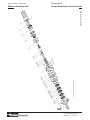
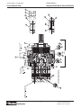
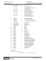
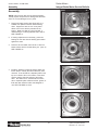
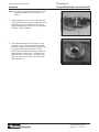
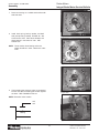
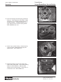
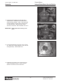
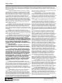
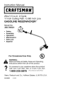
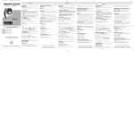
Service Bulletin 1516-M1/USA
Hydraulics
LSHT-120A
Parker Motors
Effective: August, 1999
Integral Brake Motor
Service Bulletin
Parker Motors
Integral Brake Motor Service Bulletin
Service Bulletin 1516-M1/USA
Table of Contents
TG Series Integral Brake Motor Exploded View ......................................... 3
TG Series Integral Brake Motor Parker Section .......................................... 4
TG Series Integral Brake Motor Parts List .................................................. 5
Tool Required .......................................................................................... 6
Disassembly
..................................................................................... 6 - 9
Assembly
................................................................................ 10- 14
Offer of Sale
........................................................................................ 15
NOTE:
REFER TO SERVICE MANUAL 1512-XXX FOR TG SERIES STANDARD
MOTOR PARTS LIST, DISASSEMBLY AND ASSEMBLY INSTRUCTIONS.
Warning:
Protective eye wear should be worn during all maintenance procedures. Springs and
seals should be serviced at or before 1/2 million brake cycles.
WARNING
FAILURE OR IMPROPER SELECTION OR IMPROPER USE OF THE PRODUCTS AND/OR SYSTEMS DESCRIBED
HEREIN OR RELATED ITEMS CAN CAUSE DEATH, PERSONAL INJURY AND PROPERTY DAMAGE.
This document and other information from Parker Hannifin, its subsidiaries and authorized distributors provide product and/
or system options for further investigation by users having technical expertise. It is important that you analyze all aspects
of your application and review the information concerning the product or system in the current product catalog. Due to the
variety of operating conditions and applications for these products or systems, the user, through its own analysis and testing,
is solely responsible for making the final selection of the products and systems and assuring that all performance, safety
and warning requirements of the application are met.
The products described herein, including without limitation, product features, specifications, designs, availability and pricing,
are subject to change by Parker Hannifin and its subsidiaries at any time without notice.
Offer of Sale
The items described in this document are hereby offered for sale by Parker Hannifin, its subsidiaries or its authorized distributors.
This offer and its acceptance are governed by the provisions stated on the separate page of this document entitled "Offer of Sale".
C
Copyright 1999, Parker Hannifin Corporation, All Rights Reserved
2
Parker Hannifin Corporaiton
Hydraulic Pump/Motor Divisioni
Greeneville, TN 37745 USA
Parker Motors
Integral Brake Motor Service Bulletin
Service Bulletin 1516-M1/USA
1
24
25
26
5
27
9
17
16
17
16
17
16
17
16
17
16
22
21
20
19
14
18
15
3
11
10
11
13
12
6
7
8
23
4
34
34
34
34
34
33
Standard Seal Kit # 3644
Exploded Assembly View
3
Parker Hannifin Corporation
Hydraulic Pump/Motor Division
Greeneville, TN 37745 USA
33
TORQUE TO 50+5 FT LBS
[68+7 N m] (7 BOLTS)
4
13
34
3
19
4
15
20
10
21
22
14
Item #1
11
16
2
8
17
9
7
6
5
ADD 175+5 CC OF
30 WT SAE OIL
28
29
23
31
30
24
32
25
26
27
Cross Section View
ASSEMBLE WITH WEDGE SIDE
DOWN INTO COMMUTATOR FACE
34
12
Torque (4) four
1/2-13 bolts to
13
90+ ft. Lbs.
[122+7Nm]
18
Service Bulletin 1516-M1/USA
Parker Motors
Integral Brake Motor Service Bulletin
Parker Hannifin Corporaiton
Hydraulic Pump/Motor Divisioni
Greeneville, TN 37745 USA
Parker Motors
Integral Brake Motor Service Bulletin
Service Bulletin 1516-M1/USA
Service Parts List
ITEM # PART NUMBER
QTY
DESCRIPTION
1
ME012062B2
1
1
ME012062B1
1
2
ME012062A1
1
3
ME012063A1
1
3
ME012065A1
1
3
ME012066A1
1
4
4
4
4
ME019038
ME019044
ME019039
ME019040
1
1
1
1
1 1/4 Taper Coupling Shaft
1 3/8 Taper Coupling Shaft
1 1/4 Straight Keyed Coupling Shaft
1 1/4 14 Tooth Spline Coupling Shaft
5
6
7
8
9
10
11
12
13
14
15
16
17
18
19
20
21
22
23
24
25
26
27
28
29
30
31
32
33
34
478035 Kit
028537 Kit
028538 Kit
032836 Kit
068027
069022
069023
071019
021466
490109
401704
490108
490107
032305
028519
032846
032847
028520
G124554
025126
025152
025113
025154
401333
039028
028413
028992
G223734
032435
032819
1
1
1
1
1
1
2
1
4
1
8
5
5
1
1
1
1
1
1
1
1
1
1
1
1
1
1
1
1
5
Dirt & Water Seal
Back Up Ring
Back Up Washer
Shaft Seal
Bearing
Bearing
Washer
Bearing
1/2-13 Bolts
Piston
Gold Springs
Separator Plate
Friction Plate
O-Ring (Housing)
Back Up Ring (Piston)
O-Ring (Piston)
O-Ring (Piston)
Back Up Ring (Piston)
Woodruff Key (for ME019038)
Standard Patch Nut (for ME019038)
Standard Castle Nut (for ME019038)
Zinc Patch Nut (for ME019038)
Zinc Castle Nut (for ME019038)
Retaining Ring (for ME019039)
Straight Key (for ME019039)
1 Flat Washer (for ME019039)
Lock Washer (for ME019039)
Screw (for ME019039)
Commutator Seal
Seal Ring
Only
Only
Only
Only
Front Brake Assembly
(need port size 7/16-20 relief port)
Front Brake Assembly
(thru mount holes)
Front Housing Assembly
(7/16-20 with thru mount holes)
Rear Housing Assembly
(9/16-18 with tap mount holes)
Rear Housing Assembly
(7/8-14 with thru mount holes)
Rear Housing Assembly
(7/8-14 with tap mount holes)
SERVICE KITS:
Seal Kit Part Number:
3644
(consist of items 5, 6, 7, 8, 18, 19, 20, 21, 22, 33 and 34)
5
Parker Hannifin Corporation
Hydraulic Pump/Motor Division
Greeneville, TN 37745 USA
Parker Motors
Integral Brake Motor Service Bulletin
Service Bulletin 1516-M1/USA
Required Tools & Disassembly
Required Tools
·
·
·
·
·
·
·
Soft-faced hammer
Small pry bar or flat tip screwdriver
1/2 in. 12 pt. socket
Snap ring pliers
O-ring lubricant
Bearing installation tool
A stable work platform (i.e. a vice or four 2 x 6
wood blocks)
SAE 30 Wt Motor Oil
·
For release pressure testing:
Hydraulic hand pump or port-a-power with a pressure
gauge and 7/16-20 UNF-2A straight thread o-ring fitting
on the pump hose.
Figure D1
Disassembly
NOTE: Cleanliness is important when working with
hydraulics. Make sure that the working area is clean
before starting disassembling of brake motor. Always
remove the motor from the application.
1.
Position the brake motor assembly with the shaft
down. Make sure the unit is secured in a vice or
other suitable device. SEE FIGURE D1
2.
Make an alignment mark on the motor and brake
assembly prior to disassembly. SEE FIGURE D2
3.
Remove the key and/or nut from the end of the
shaft.
4.
Remove the seven hex bolts from the hydraulic
motor and disassemble motor. Inspect motor
components for abnormal wear or damage. Replace any worn or damaged parts. SEE FIGURE
D3
Figure D2
See Service Manual 1512-XXX for TG Series
Standard Motor Disassembly Instructions.
5.
Figure D3
Tap up on end of shaft and remove shaft from
brake assembly. Inspect the shaft for abnormal
wear or damage. Replace shaft if worn or damaged. SEE FIGURE D4
Figure D4
6
Parker Hannifin Corporaiton
Hydraulic Pump/Motor Divisioni
Greeneville, TN 37745 USA
Parker Motors
Integral Brake Motor Service Bulletin
Service Bulletin 1516-M1/USA
Disassembly
6.
Remove the four brake housing bolts. The bolts
are under spring load and should be loosened
gradually and uniformly. Remove rear brake
housing assembly. SEE FIGURE D5
Figure D5
7.
The internal components of the brake will now be
exposed. The case seal o-ring will be attached to
the motor flange pilot. SEE FIGURE D6
Figure D6
8.
Remove springs from brake housing. Note
spacing of springs. Inspect springs and replace
springs if damaged, broken, or discolored from
heat. SEE FIGURE D7
Figure D7
7
Parker Hannifin Corporation
Hydraulic Pump/Motor Division
Greeneville, TN 37745 USA
Parker Motors
Integral Brake Motor Service Bulletin
Service Bulletin 1516-M1/USA
Disassembly
9.
DANGER. Use extreme caution when removing the
piston. Remove the piston from the brake assembly, cover the piston with a rigid restraint and apply
low pressure air (10 - 20 psi) to the brake release
port. The piston will slide up until released. To
much pressure could cause the piston to blow out of
its bore causing personal harm. SEE FIGURE D8
& FIGURE D9
Figure D8
Figure D9
10. Note arrangement of friction discs and separator
plates. There should be five of each in alternating
order with a friction disc first in the bottom of the
case and friction plate will be last. Separator plate
on top. SEE FIGURE D10
11. Remove friction discs and separator plates.
Replace any friction discs or separator plates that
are damaged, warped, or excessively worn. Friction
disc serviceable limit is .142" minimum. Separator
plate serviceable limit is .093" minimum.
Figure D10
8
Parker Hannifin Corporaiton
Hydraulic Pump/Motor Divisioni
Greeneville, TN 37745 USA
Parker Motors
Integral Brake Motor Service Bulletin
Service Bulletin 1516-M1/USA
Disassembly
12. Remove and discard o-rings and back up rings
from piston. Note position of o-rings and back up
rings. Install new o-rings and back up rings on
piston in the same order as removed. SEE
FIGURE D11
Figure D11
13. Inspect radial needle bearing, thrust bearing, and
thrust washers in rear housing. The radial bearing
must be removed to replace thrust bearing and
thrust washers. Use a bearing puller to remove the
bearing. If original bearing is removed a new
bearing must be used during reassembly. SEE
FIGURE D12
Figure D12
14. Remove lip seal package from rear housing. SEE
FIGURE D13
NOTE: Remove shaft seal, back up washer, back up
ring in this order. Inspect for any abnormal
wear. If abnormal wear is indicated replace
with a new seal kit #3644.
CAUTION: Do not scratch seal bore when removing
the seal as this will create a leak path.
Figure D13
9
Parker Hannifin Corporation
Hydraulic Pump/Motor Division
Greeneville, TN 37745 USA
Parker Motors
Integral Brake Motor Service Bulletin
Service Bulletin 1516-M1/USA
Assembly
Assembly
NOTE: Parts must be clean and dry before assembly.
Visually inspect components for damage and abnormal
wear. Do not use damaged or worn parts.
1.
Place front brake housing case (front half) on a
suitable work platform with the needle bearing
down. Support the case in such a way that it
allows room for the shaft to protrude out the
bottom. Make sure that the unit is secured. If
radial bearing is not being replaced skip to step 3.
SEE FIGURE A1
2.
If bearing replacement is necessary, press new
bearing into the case with the bearing part number
against the arbor.
3.
Press the dirt and water seal in flush to .020 inch
below surface with the flat side facing out. (Item 5)
SEE FIGURE A2
Figure A1
Figure A2
4.
Install the separator (metal tab plates) plates and
friction discs in exactly the same order they were
removed. There should be a separator plate on the
top and a friction disc on the bottom of the stack.
Use the shaft to align the splines of the friction
discs. Be careful not to contaminate the friction
disc or separator plate surfaces with dirt, grease, or
fluid other than what the brake was designed to
use. SEE FIGURES A3 & A4
Figure A3
Figure A4
10
Parker Hannifin Corporaiton
Hydraulic Pump/Motor Divisioni
Greeneville, TN 37745 USA
Parker Motors
Integral Brake Motor Service Bulletin
Service Bulletin 1516-M1/USA
Assembly
NOTE: Use shaft for alignment of friction discs. After
alignment remove shaft and continue on to
step 5.
5.
Always replace the piston o-rings and piston backup rings, be sure the o-rings are nearest each other
with back up rings to the outside of the O-Rings.
Lightly lubricate piston bores and o-rings with SAE
30 Wt oil. SEE FIGURE A6
Figure A6
6.
Gently slide piston into case until larger o-ring is
against the case. Using a light duty press, push
the piston completely into the bore (be careful not
to damage seals or back-up rings). This will
squeeze the o-rings and back-up rings and set the
piston against the friction pack. Use shaft as an
alignment tool for spline disk. After alignment of
disk, both piston and sea, then remove the shaft.
SEE FIGURE A7
Figure A7
11
Parker Hannifin Corporation
Hydraulic Pump/Motor Division
Greeneville, TN 37745 USA
Parker Motors
Integral Brake Motor Service Bulletin
Service Bulletin 1516-M1/USA
Assembly
7.
Place rear housing on a suitable work surface with
seal side down.
8.
Install back-up ring, back-up washer, and shaft
seal (seal lip facing inwards) FIGURE A8. See
Cross Section View. Place thrust washers and
thrust bearing in the bottom of case. SEE
FIGURE A9
Figure A8
NOTE: Thrust washer, thrust bearing and thrust
washer should be in order. Make sure of this
order.
Figure A9
9.
If input bearing was removed, press a new bearing
into the case with the bearing part number against
the arbor. SEE FIGURES A10 & A11
Figure A10
NOTE: Dimension below surface:
.125
.105
Bearing
Figure A11
12
Parker Hannifin Corporaiton
Hydraulic Pump/Motor Divisioni
Greeneville, TN 37745 USA
Parker Motors
Integral Brake Motor Service Bulletin
Service Bulletin 1516-M1/USA
Assembly
10. Invert rear housing so that the spring pockets are
facing up. Place springs into the pockets. Brake
may have 4, 6, or 8 springs, arrange springs in a
symmetrical pattern. Add approximately 175 cc
(ml) of SAE 30 motor oil around spring pockets.
SEE FIGURES A12 & A13
Figure A12
Figure A13
11. Install o-ring on piston housing. Ensure item #14,
o-ring, is in place. Make sure O-Ring lays flat
against flange. SEE FIGURE A14
Figure A14
12. Place front housing on top of rear housing and
install brake housing bolts. Torque brake housing
bolts in a uniform sequence. Align the brake
release port to the front housing. Finish torque on
4 bolts is 90 ft. lbs. SEE FIGURE A15
Figure A15
13
Parker Hannifin Corporation
Hydraulic Pump/Motor Division
Greeneville, TN 37745 USA
Parker Motors
Integral Brake Motor Service Bulletin
Service Bulletin 1516-M1/USA
Assembly
13. Pressurize brake release port with 350 psig to
release brake. Install shaft from bottom side of
brake housing assembly. (Note: shaft must pass
through all spines of friction discs and then push
into the shaft seal.) Lightly tap with a rubber
hammer to seat shaft. SEE FIGURES A16 & A17
Figure A16
IMPORTANT: Rotate shaft while inserting it into
place.
Figure A17
14. Invert brake assembly so that the motor is facing
up. Keep PSI on brake assembly so rotor set can
be aligned easily. SEE FIGURE A18
Figure A18
15. Assemble the hydraulic motor components as a
regular assembly procedure. Refer to Service
Manual 1512-XXX for these instructions.
14
Parker Hannifin Corporaiton
Hydraulic Pump/Motor Divisioni
Greeneville, TN 37745 USA
Parker Motors
Integral Brake Motor Service Bulletin
Service Bulletin 1516-M1/USA
Offer of Sale
The items described in this document and other documents or descriptions provided by Parker Hannifin, its subsidiaries and its authorized
distributors are hereby offered for sale at prices to be established by Parker Hannifin, its subsidiaries and its authorized distributors. This
offer and its acceptance by any customer (“Buyer”) shall be governed by all of the following Terms and Conditions. Buyer’s order for any
such item, when communicated to Parker Hannifin, its subsidiary or an authorized distributor (“Seller”) verbally or in writing, shall constitute
acceptance of this offer.
right to alter, discard or otherwise dispose of any special tooling or other
1. Terms and Conditions of Sale: All descriptions, quotations,
property in its sole discretion at any time.
proposals, offers, acknowledgments, acceptances and sales of Seller’s
products are subject to and shall be governed exclusively by the terms
8. Buyer’s property: Any designs, tools, patterns, materials,
and conditions stated herein. Buyer’s acceptance of any offer to sell is
drawings. Confidential information or equipment furnished by buyer, or
limited to these terms and conditions. Any terms or conditions in addition
any other items which become Buyer’s property, may be considered
to, or inconsistent with those stated herein, proposed by Buyer in any
obsolete and may be destroyed by Seller after two (2) consecutive years
acceptance of an offer by Seller, are hereby objected to. No such
have elapsed without Buyer placing an order for the items which are
additional, different or inconsistent terms and conditions shall become part manufactured using such property. Seller shall not be responsible for
of the contract between Buyer and Seller unless expressly accepted in
any loss or damage to such property while it is in Seller‘s possession or
writing by Seller. Seller’s acceptance of any offer to purchase by Buyer is control.
expressly conditional upon Buyer’s assent to all the terms and conditions
9. Taxes: Unless otherwise indicated on the face hereof, all
stated herein, including any terms in addition to, or inconsistent with those
prices and charges are exclusive of excise, sales, use, property,
contained in Buyer’s offer. Acceptance of Seller’s products shall in all
occupational or like taxes which may be imposed by any taxing authority
events constitute such assent.
upon the manufacture, sale or delivery of the items sold hereunder. If
2. Payment: Payment shall be made by Buyer net 30 days from
any such taxes must be paid by Seller or if Seller is liable for the collection
the date of delivery of the items purchased hereunder. Amounts not timely of such tax, the amount hereof shall be in addition to amounts for the
paid shall bear interest at the maximum rate permitted by law for each
items sold. Buyer agrees to pay all such taxes or to reimburse Seller
month or portion thereof that the Buyer is late in making payment. Any
therefore upon receipt of its invoice. If Buyer claims exemption from any
claims by Buyer for omissions or shortages in a shipment shall be waived sales, use or other tax imposed by any taxing authority, Buyer shall save
unless Seller receives notice thereof within 30 days after Buyer’s receipt of Seller harmless from and against any such tax together with any interest
the shipment.
or penalties thereon which may be assessed if the items are held to be
taxable.
3. Delivery: Unless otherwise provided on the face hereof,
delivery shall be made F.O.B. Seller’s plant. Regardless of the method of
10. Indemnity For Infringement of Intellectual Property
delivery, however, risk of loss shall pass to Buyer upon Seller’s delivery to Rights: Seller shall have no liability for infringement of any patents,
a carrier. Any delivery dates shown are approximate only and Seller shall trademarks, copyrights, trade dress, trade secrets or similar rights
have no liability for any delays in delivery.
except as provided in this Part 10. Seller will defend and indemnify Buyer
against allegations of infringement of U.S. patents, U.S. Trademarks,
4. Warranty: Seller warrants that the items sold hereunder shall
copyrights, trade dress and trade secrets (hereinafter “Intellectual
be free from defects in material or workmanship for a period of 18 months
Property Rights). Seller will defend at its expense and will pay the cost of
from date of shipment from Parker Hannifin Corporation. THIS WARany settlement or damages awarded in an action brought against Buyer
RANTY COMPROMISES THE SOLE AND ENTIRE WARRANTY
PERTAINING TO ITEMS PROVIDED HEREUNDER. SELLER MAKES based on an allegation that an item sold pursuant to this contract infringes
NO OTHER WARRANTY, GUARANTEE, OR REPRESENTATION OF the Intellectual Property Rights of a third party. Seller’s obligation to
ANY KIND WHATSOEVER. ALL OTHER WARRANTIES, INCLUDING defend and indemnify Buyer is contingent on Buyer notifying Seller within
ten (10) days after Buyer becomes aware of such allegations of
BUT NOT LIMITED TO, MERCHANTABILITY AND FITNESS FOR
infringement, and Seller having sole control over the defense of any
PURPOSE, WHETHER EXPRESS, IMPLIED, OR ARISING BY
OPERATION OF LAW. TRADE USAGE, OR COURSE OF DEALING allegations or actions including all negotiations for settlement or compromise. If an item sold hereunder is subject to a claim that it infringes the
ARE HEREBY DISCLAIMED.
Intellectual Property Rights of a third party, Seller may, at its sole
NOTWITHSTANDING THE FOREGOING, THERE ARE NO
expense and option, procure for Buyer the right to continue using said
WARRANTIES WHATSOEVER ON ITEMS BUILT OR ACQUIRED
item, replace or modify said item so as to make it noninfringing, or offer to
WHOLLY OR PARTIALLY, TO BUYER’S DESIGNS OR SPECIFICAaccept return of said item and return the purchase price less a reasonTIONS.
able allowance for depreciation. Notwithstanding the foregoing, Seller
5. Limitation of Remedy: SELLER’S LIABILITY ARISING
shall have no liability for claims of infringement based on information
FROM OR IN ANY WAY CONNECTED WITH THE ITEMS SOLD OR
provided by Buyer, or directed to items delivered hereunder for which the
THIS CONTRACT SHALL BE LIMITED EXCLUSIVELY TO REPAIR
designs are specified in whole or part by Buyer, or infringements
OR REPLACEMENT OF THE ITEMS SOLD OR REFUND OF THE
resulting from the modification, combination or use in a system of any
PURCHASE PRICE PAID BY BUYER, AT SELLER’S SOLE OPTION.
item sold hereunder. The foregoing provisions of this Part 10 shall
IN NO EVENT SHALL SELLER BE LIABLE FOR ANY INCIDENTAL,
constitute Seller’s sole and exclusive liability and buyer’s sole and
CONSEQUENTIAL OR SPECIAL DAMAGES OF ANY KIND OR
exclusive remedy for infringement of Intellectual Property Rights.
NATURE WHATSOEVER. INCLUDING BUT NOT LIMITED TO LOST
If a claim is based on information provided by Buyer or if the
PROFITS ARISING FROM OR IN ANY WAY CONNECTED WITH
design for an item delivered hereunder is specified in whole or in part by
THIS AGREEMENT OR ITEMS SOLD HEREUNDER, WHETHER
Buyer, buyer shall defend and indemnify Seller for all costs, expenses of
ALLEGED TO ARISE FROM BREACH OF CONTRACT, EXPRESS
or judgments resulting from any claim that such item infringes any patent,
OR IMPLIED WARRANTY, OR IN TORT, INCLUDING WITHOUT
trademark, copyright, trade dress, trade secret or any similar right.
LIMITATION, NEGLIGENCE, FAILURE TO WARN OR STRICT
11. Force Majeure: Seller does not assume the risk of and shall
LIABILITY.
not be liable for delay or failure to perform any of Seller’s obligations by
6. Changes, Reschedules and Cancellations: Buyer may
reason of circumstances beyond the reasonable control of Seller
request to modify the designs or specification for items sold hereunder as
(hereinafter “Events of Force Majeure”). Events of Force Majeure shall
well as the quantities and delivery dates thereof, or may request to cancel include without limitation, accidents, acts of god, strikes or labor disputes,
all or part of this order, however, no such requested modification or
acts, laws, rules or regulations of any government or government
cancellation shall become part of the contract between buyer and Seller
agency, fires, floods, delays or failures in delivery of carries or suppliers,
unless accepted by Seller in written amendment to this Agreement.
shortages of materials and any other cause beyond Seller’s control.
Acceptance of any such requested modification or cancellation shall be at
12. Entire Agreement/Governing Law: The terms and
Seller’s discretion, and shall be upon such terms and conditions as Seller
conditions set forth herein, together with any amendments, modifications
may require.
and any different terms or conditions expressly accepted by Seller in
7. Special Tooling: A tooling charge may be imposed for any
writing, shall constitute the entire Agreement concerning the items sold,
special tooling, including without limitation, dies, fixtures, molds and
and there are no oral or other representation or agreements which
patterns, acquired to manufacture items sold pursuant to this contract.
pertain thereto. This Agreement shall be governed in all respects by the
Such special tooling shall be and remain Seller’s property notwithstanding
law of the State of Ohio. No actions arising out of the sale of the items
payment of any charges byBuyer, in no event will Buyer acquire any
sold hereunder or this Agreement may be brought by either party more
interest in apparatus belonging to Seller which is utilized in the manufacture than two (2) years after the cause of action accrues.
of the items sold hereunder, even if such apparatus has been specially
converted or adapted for such manufacture and notwithstanding any
FPG 9-91-P
charges paid by Buyer. Unless otherwise agreed, Seller shall have the
15
Parker Hannifin Corporation
Hydraulic Pump/Motor Division
Greeneville, TN 37745 USA
Hydraulics
Parker Hannifin Corporation
Hydraulic Pump/Motor Division
2745 Snapps Ferry Road
Greeneville, TN 37745 USA
Tel. (423) 639-8151
FAX (423) 787-2418
www.parker.com/pumpmotor
Pinnacle Printing 5000 7/99