1
Bulletin HY13-1650-M1/US
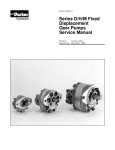
Piston Pumps
Service Procedure
P2 / P3 Series
Variable Volume
Piston Pumps
Piston Pump Service Procedure
P2 / P3 Series
Bulletin HY13-1650-M1/USA
WARNING
FAILURE OR IMPROPER SELECTION OR IMPROPER USE OF THE PRODUCTS AND/OR SYSTEMS DESCRIBED HEREIN OR
RELATED ITEMS CAN CAUSE DEATH, PERSONAL INJURY AND PROPERTY DAMAGE.
This document and other information from Parker Hannifin Corporation, its subsidiaries and authorized distributors provide product and/or
system options for further investigation by users having technical expertise. It is important that you analyze all aspects of your application
and review the information concerning the product or system in the current product catalog. Due to the variety of operating conditions and
applications for these products or systems, the user, through its own analysis and testing, is solely responsible for making the final selection
of the products and systems and assuring that all performance, safety and warning requirements of the application are met.
The products described herein, including without limitation, product features, specifications, designs, availability and pricing, are subject to
change by Parker Hannifin Corporation and its subsidiaries at any time without notice.
Offer of Sale
The items described in this document are hereby offered for sale by Parker Hannifin Corporation, its subsidiaries or its authorized distributors.
This offer and its acceptance are governed by the provisions stated in the "Offer of Sale".
¤
¤ Copyright 2002, Parker Hannifin Corporation, All Rights Reserved
2
Parker Hannifin Corporation
Hydraulic Pump/Motor Division
Greeneville, Tennessee US
Bulletin HY13-1650-M1/USA
Table of Contents
Piston Pump Service Procedure
P2 / P3 Series
Definitions ............................................................................................................................................................... 3
Design Features ................................................................................................................................................... 4-5
Introduction ............................................................................................................................................................. 6
Troubleshooting Guide ............................................................................................................................................. 7
Troubleshooting Checklist .................................................................................................................................... 8-9
Tools and Material Required for Servicing ................................................................................................................ 9
Technical Information ....................................................................................................................................... 10-11
P2060 Service Instructions .............................................................................................................................. 13-22
P2075 Service Instructions .............................................................................................................................. 23-32
P2105 Service Instructions .............................................................................................................................. 33-42
P2145 Service Instructions .............................................................................................................................. 43-52
P3075 Service Instructions .............................................................................................................................. 53-62
P3105 Service Instructions .............................................................................................................................. 63-72
P3145 Service Instructions .............................................................................................................................. 73-82
Compensator Kits ............................................................................................................................................ 83-87
Torque Controls ..................................................................................................................................................... 88
Preparation for Disassembly ................................................................................................................................. 89
Disassembly & Inspection P2060-P2/P3075 .................................................................................................... 90-93
Assembly P2060-P2/P3075 ............................................................................................................................. 94-99
Disassembly & Inspection P2/P3105-145 .................................................................................................... 100-105
Assembly P2/P3105-145 .............................................................................................................................. 106-111
Final Checks & Requirements ............................................................................................................................. 112
Tips for Maintaining the System .......................................................................................................................... 113
Offer of Sale ....................................................................................................................................................... 119
Definitions
NOTE:
CAUTION:
WARNING:
A NOTE provides key information to make a procedure easier or quicker to complete.
A CAUTION refers to procedure that must be followed to avoid damaging the Pump or other system
components.
A WARNING REFERS TO PROCEDURE THAT MUST BE FOLLOWED FOR THE SAFETY OF THE
EQUIPMENT OPERATOR AND THE PERSON INSPECTING OR REPAIRING THE PUMP.
Disclaimer
This Service Manual has been prepared by Parker Hannifin for reference and use by mechanics who have been trained to
repair and service hydraulic pumps and systems on commercial and noncommercial equipment applications. Parker
Hannifin has exercised reasonable care and diligence to present accurate, clear and complete information and instructions
regarding the techniques and tools required for maintaining, repairing and servicing the complete line of Parker P2 & P3
Pump Units. However, despite the care and effort taken in preparing this general Service Manual, Parker makes no warranties that (a) the Service Manual or any explanations, illustrations, information, techniques or tools described herein are
either accurate, complete or correct as applied to a specific Pump unit, or (b) any repairs or service of a particular Pump unit
will result in a properly functioning Pump unit.
If inspection or testing reveals evidence of abnormal wear or damage to the Pump unit or if you encounter circumstances not
covered in the Manual, STOP – CONSULT THE EQUIPMENT MANUFACTURER’S SERVICE MANUAL AND WARRANTY.
DO NOT TRY TO REPAIR OR SERVICE A PUMP UNIT WHICH HAS BEEN DAMAGED OR INCLUDES ANY PART THAT
SHOWS EXCESSIVE WEAR UNLESS THE DAMAGED AND WORN PARTS ARE REPLACED WITH ORIGINAL PARKER
REPLACEMENT AND SERVICE PARTS AND THE UNIT IS RESTORED TO PARKER SPECIFICATIONS FOR THE PUMP
UNIT.
It is the responsibility of the mechanic performing the maintenance, repairs or service on a particular Pump unit to (a) inspect
the unit for abnormal wear and damage, (b) choose a repair procedure which will not endanger his/her safety, the safety of
others, the equipment, or the safe operation of the Pump, and (c) fully inspect and test the Pump unit and the hydraulic
system to insure that the repair or service of the Pump unit has been properly performed and that the Pump and hydraulic
system will function properly.
3
Parker Hannifin Corporation
Hydraulic Pump/Motor Division
Greeneville, Tennessee US
Piston Pump Service Procedure
P2 / P3 Series
Bulletin HY13-1650-M1/USA
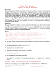
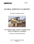
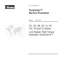
Pump Design Features
P2 Series
Note:
Picture illustrates
P2-060 & P2-075
construction.
(Torque Control
Option not shown).
1
1.
2.
3.
4.
2
3
4
5
Input shaft
Seal carrier with shaft seal
Spherical roller bearing
Saddle bearing
6
5.
6.
7.
8.
7
8
Swashplate
Ball seat
Retainer
Housing
9
10
9.
10.
11.
12.
13.
11
12
13
Piston with piston shoe
Valve plate
Servo piston
Control
Rear cover
P2 Series Piston Pump features include:
• New functionality adds value - Parker’s line of variable piston pumps are compact, with a low noise level and a high selfpriming speed. Our new pump line also boasts a unique port layout and generates less pressure pulsations than previous
designs.
• Compact and easy to install - Attaching this pump to your machinery is easy because of its compact design and unique
port layout. Normally it will not require an offset gearbox, which will lower the total installation cost.
• Less noise to insulate - The rigid housing design, combined with the reduced pressure ripple, decreases airborne as well
as hydraulic generated noise. These features will significantly reduce the need for costly insulation.
• Reliable - High self-priming speed and the reduced pressure ripple increase the service life of
the pump while lowering maintenance costs of the system.
• Flexible - The modular design of the P2 line will readily accommodate future control variations.
- Adjustable maximum displacement stop is standard.
- Inlet and outlet gage ports are standard.
4
Parker Hannifin Corporation
Hydraulic Pump/Motor Division
Greeneville, Tennessee US
Piston Pump Service Procedure
P2 / P3 Series
Bulletin HY13-1650-M1/USA
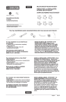
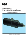
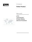
Pump Design Features
P3 Series
15
Note:
Picture illustrates
P3-075 construction.
14
1
1.
2.
3.
4.
5.
2
3
4
5
6
Input shaft
6.
Seal carrier with shaft seal 7.
Spherical roller bearings
8.
Saddle bearing
9.
Swashplate
10.
7
8
9
10
Slipper retainer
Ball seat
Housing
Impeller
Piston assembly
11
12
11.
12.
13.
14.
15.
13
Servo piston
Compensator control
Rear cover
Air bleed
Torque control cartridge
P3 Series Piston Pump features include:
• All the same advantages of the P2 Series, namely a reliable, compact package with very low noise levels.
• Because of the unique built in impeller, P3 offers significantly higher self priming speeds than competitive designs and the
capability to operate the pump successfully at high elevations, without the need for pressurized reservoirs.
• Unique port layout with both operating ports on the same side of the pump, resulting in more accessible plumbing.
• Built in air bleed valve for automatic priming of the pump at start up.
5
Parker Hannifin Corporation
Hydraulic Pump/Motor Division
Greeneville, Tennessee US
Bulletin HY13-1650-M1/USA
Introduction
Piston Pump Service Procedure
P2 / P3 Series
This service manual has one purpose: to guide you in
maintaining, troubleshooting, and servicing the P2 & P3
series piston pumps.
Material in this manual is organized so you can work on
the Pump and get results without wasting time or being
confused. To get these results, you should read this
entire manual before you begin any work on the Pump.
This manual also contains troubleshooting information
and checklist. If you must service the Pump, the
checklist will help you to determine where the problem
may be.
The three-column format of the Disassembly and
Inspection, and Assembly sections will make it easier
for you to conduct work on the Pump. Column 1 gives a
brief key for each procedure. Column 2 explains in
detail the procedure you should follow. Column 3
illustrates this procedure with photographs. Read all
material carefully and pay special attention to the
notes, cautions, and warnings.
Pages with the various pump sizes exploded assembly
view are provided several places in this manual. The
component part names and item numbers assigned on
these exploded assembly views correspond with names
and item numbers (in parentheses) used in the disassembly and assembly procedures set forth in this
manual.
Service part list charts are also provided in this manual
with the part names and exploded view item numbers
cross referenced to Parker service part numbers.
Service parts are available through the Original Equipment Manufacturer or Parker approved P2 & P3 Distributors.
As you gain experience in servicing the Pump, you may
find that some information in this manual could be clearer
or more complete. If so, let us know about it. Do not try to
second guess the manual. If you are stuck, contact us.
Servicing the Pump should be a safe and productive
procedure, in order for the unit to deliver the reliable, longlife operation engineered into it.
6
Parker Hannifin Corporation
Hydraulic Pump/Motor Division
Greeneville, Tennessee US
Bulletin HY13-1650-M1/USA
Troubleshooting Guide
Piston Pump Service Procedure
P2 / P3 Series
NOTE: Before troubleshooting any system problem, check service literature published by the equipment and/or
component manufacturers. Follow their instructions, if given, for checking any component other than the Pump unit.
Preparation
Hydraulic Components
Make your troubleshooting easier by preparing as
follows:
• work in a clean, well-lighted place;
• have proper tools and materials nearby;
• have an adequate supply of clean petroleum-based
solvent.
If you think the problem is caused by a hydraulic
component, start by checking the easy-to-reach items.
Check all hoses and lines for cracks, hardening, or
other signs of wear. Reroute any usable hoses that are
kinked, severely bent, or that rest against hot engine
parts. Look for leaks, especially at couplings and
fittings. Replace any hoses or lines that don’t meet
system flow and pressure ratings.
Next, go to the reservoir and filter or filters. Check fluid
level and look for air bubbles. Check the filter(s).
20/18/14 filtration is recommended per ISO 4406.
Visually check other components to see if they are
loosely mounted, show signs of leaks, or other damage
or wear.
Excessive heat in a hydraulic system can create
problems that can easily be overlooked. Every system
has its limitation for the maximum amount of temperature. After the temperature is attained and passed, the
following can occur:
• oil seal leaks
• loss of efficiency
• pump loss of efficiency
• pump failure
• hoses become hard and brittle
• hose failure
WARNING: SINCE SOLVENTS ARE FLAMMABLE, BE
EXTREMELY CAREFUL WHEN USING ANY SOLVENT, EVEN A SMALL EXPLOSION OR FIRE COULD
CAUSE INJURY OR DEATH.
WARNING: WEAR EYE PROTECTION AND BE SURE
TO COMPLY WITH OSHA AND OTHER MAXIMUM AIR
PRESSURE REQUIREMENTS.
Preliminary Checks
Hydraulic systems are often trouble-free. Hence, the
problem an operator complains of could be cause by
something other than the hydraulic components.
Thus, once you have determined that a problem exists,
start with the easy-to-check items, such as:
• parts damaged from impact that were not properly
repaired, or that should have been replaced; and
• improper replacement parts used in previous
servicing
• mechanical linkage problems such as binding,
broken, or loose parts or slipping belts
A normal temperature range means an efficient hydraulic system. Consult the manuals published by equipment and/or component manufacturers for maximum
allowable temperature and hydraulic tests that may be
necessary to run on the performance of the hydraulic
components. The pump is not recommended for hydraulic systems with maximum temperatures above 70°C
(158°F).
Normal working temperatures are 0° - 70°C (-32° 158°F).
Maximum case drain temperature is 90°C (194°F).
7
Parker Hannifin Corporation
Hydraulic Pump/Motor Division
Greeneville, Tennessee US
Piston Pump Service Procedure
P2 / P3 Series
Bulletin HY13-1650-M1/USA
Troubleshooting Checklist
Trouble
Cause
Remedy
Oil Leakage
1. Hose fittings loose, worn or
damaged.
Check & replace damaged
fittings or “O” Rings. Torque to
manufacturers specifications.
Replace oil seal rings by disassembling Pump unit.
2.Oil seal rings deteriorated by
excess heat.
3.Bolt loose or its sealing area
deteriorated by corrosion.
(a) Loosen then tighten single bolt to
torque specification.
(b) Replace bolt.
4.Shaft seal worn or damaged.
(a) If pump is single shaft seal option:
- Remove seal carrier from pump.
- Remove damaged seal from seal
carrier.
- If shaft is worn, install new seal in the
inner position.
- Reinstall seal carrier.
(b) If pump is dual shaft seal option:
- Remove seal carrier from pump.
- If shaft is damaged or worn, replace
shaft and seals.
- If shaft is not damaged, replace seals
and reinstall seal carrier.
NOTE: Check fluid leaking from housing weep
hole to better determine which seal has failed.
If pump is leaking hydraulic fluid the inboard
seal has failed. If the pump is leaking transmission fluid the outboard seal has failed.
1. Pump not installed correctly.
Check proper drive rotation. Make sure pump shaft
is turning (i.e. drive coupling is engaged). Check for
sources of suction leaks, inlet flange tight?
Pinched o-rings?
2. Pump not getting oil.
Make sure reservoir is full of oil.
Can’t Build Any
Pressure
1. Flow has an unrestricted path
Is it an open circuit to the reservoir.
Can only build a
few hundred PSI
(20-30 bar)
1. Pump control settings too low.
Is compensator setting backed out? If load sense,
is there a load sense pressure signal? Is the
system relief valve vented?
2. Control is malfunctioning.
Assure orifices in control are not plugged. Assure
control spools/springs are assembled correctly.
If non-torque control pump, assure m 6x6 set screw
is installed in torque control feed port.
3. Internal leakage in cylinders,
valves, motors or pumps.
Repair component.
No Flow from
Pump (If pump
does not prime in
30 seconds STOP!)
CAUTION: If the hydraulic system fluid becomes overheated [in excess of 90°C (194°F), seals in the system
can shrink, harden or crack, thus losing their sealing ability.
8
Parker Hannifin Corporation
Hydraulic Pump/Motor Division
Greeneville, Tennessee US
Bulletin HY13-1650-M1/USA
Troubleshooting Checklist
Piston Pump Service Procedure
P2 / P3 Series
Trouble
Cause
Remedy
Pump won’t
compensate
Control is malfunctioning.
Clean orifices in control of contamination. Confirm
orifice and plugs are properly assembled.
If torque control pump, is saturation orifice in place.
Tools and Materials Required for Servicing
•
•
•
•
•
•
•
•
•
•
•
•
•
•
•
•
Clean, petroleum-based solvent
Vise with soft jaws
Air pressure source
Arbor press
Screw driver
Breaker bar
Torque wrench-(Nm) ft lbs: Range: 0-425 Nm
Adjustable crescent wrench
Fluid mineral oil ISO VG 32 @ 40oC
Clean corrosion resistant grease, oil or petroleum jelly.
Hex bits and Allen Keys (or T-handle).
Metric: 3mm, 5mm, 6mm, 8mm, 10mm, 12mm and 14mm
SAE: 1/8”, 5/32”, 3/16”, 3/8”, 1/2”, 9/16” and 5/8”
Sockets (deepwall)
Metric: 17mm, 19mm, 32mm or 36 mm and 38 mm
SAE: 9/16” and 1”
Internal snapring pliers: small and large
Box end wrench: 13mm (1/2”), 17mm deep offset
Pencil magnet
Loctite 242
CAUTION: Mixing greases that have different bases can be detrimental to bearing life.
9
Parker Hannifin Corporation
Hydraulic Pump/Motor Division
Greeneville, Tennessee US
Piston Pump Service Procedure
P2 / P3 Series
Bulletin HY13-1650-M1/USA
Technical Information
CONVERSIONS
mm
0.4
0.8
1.0
1.2
1.6
2.0
3.0
4.0
5.0
10.0
15.0
20.0
25.0
25.4
INCHES
.0157
.0314
.0393
.0472
.0629
.0787
.1181
.1574
.1968
.3936
.5905
.7873
.9842
1.000
Torque Chart
Nm
2.0
4.0
5.0
10.0
11.0
12.0
13.5
20.0
25.0
ft lbs
1.48
2.95
3.68
7.37
8.11
8.85
10.0
14.75
18.43
Nm
30.0
35.0
40.0
45.0
50.0
55.0
60.0
65.0
70.0
ft lbs
22.12
25.81
29.50
33.19
36.87
40.56
44.25
47.94
51.63
Nm
75.0
80.0
85.0
90.0
95.0
100.0
125.0
150.0
200.0
ft lbs
55.32
59.00
62.69
66.38
70.06
73.76
92.19
110.63
147.51
Nm
250.0
300.0
350.0
400.0
450.0
ft lbs
184.39
221.27
258.15
295.02
331.90
Temperature
o
C = 0.56 (oF -32)
o
F = 1.8 (oC +32)
Pressure
1 PSI = .06896 Bar
1 Bar = 14.5 PSI
Length
1 inch = 0.0394 x 1mm
1mm = 25.4 x 1 inch
Torque
1 Ft-Lb = 0.738 x 1 N-m
1 In-Lb = 8.85 x 1 N-m
1 N-m = 0.113 x 1 In-Lb
10
Parker Hannifin Corporation
Hydraulic Pump/Motor Division
Greeneville, Tennessee US
Bulletin HY13-1650-M1/USA
Technical Information
Piston Pump Service Procedure
P2 / P3 Series
SERVICE NOTES:
*
*
*
*
*
Use a clean lubricant (compatible with the working fluid) on all pump components during assembly.
Thoroughly clean the reservoir, suction lines, suction strainer, drain lines, etc. before re-installing the pump.
Most premature pump failures occur when contaminants from a previous failure have not been completely
removed from the system, or cause for previous failure is still present (i.e. water in oil, filter bypassing, etc.).
Always fill the case with the clean fluid before starting a new or service pumps (fill as high as inlet port will
allow on a P3 style pump). For flooded suction, purge air from suction lines by cracking the inlet fitting or vent/
gage plug on pump body. This should prevent an airlock condition and allow for faster priming. Starting the
pump slowly by jogging (or turning over engine without allowing it to start) will help the pump prime and makes it
easier to determine when priming has occurred. Plumb P3 style pump air bleed directly to tank if pump is
mounted above tank.
Check for proper shaft rotation if there is a possibility it may have changed during a system rebuild.
Start pump with an open circuit whenever possible. Reduce the compensator to its minimum setting during
start-up. Cycle the pump on and off stroke while increasing the compensator to its required setting. This will
assist in break-in of new components and help purge air from the case.
11
Parker Hannifin Corporation
Hydraulic Pump/Motor Division
Greeneville, Tennessee US
Bulletin HY13-1650-M1/USA
Disassembly and Inspection
Piston Pump Service Procedure
P2 / P3 Series
Preparation Before Disassembly
• Before you disassemble the Pump unit or any of its components read this entire manual. It provides important
information on parts and procedures you will need to know to service the P2 or P3 Pump.
• Determine whether the Pump you are about to disassemble is the P2 or P3 Pump Series so you can follow those
procedures that pertain to that Series Pump. The first two letters of the “spec” number on the Pump identification
tag is the Series designation.
• Refer to “Tools and Materials Required for Services” section for tools and other items required to service the Pump
and have them available.
• Thoroughly clean off all outside dirt, especially from around fittings and hose connections, before disconnecting
and removing the Pump.
• Remove coupling shaft connections and hose fittings and immediately plug port holes and fluid lines.
• Remove rust or corrosion from coupling shaft..
• Remove the Pump from system, drain it of fluid and take it to a clean work surface.
• Plug all ports and wash complete pump and remove any remaining outside dirt, rust and corrosion.
• Clean and dry the Pump before you start to disassemble the unit.
• As you disassemble the Pump clean all parts, except seals, in clean petroleum-based solvent, and blow them
dry.
WARNING: petroleum-base solvents are flammable. Be extremely careful when using any solvent. Even a small
explosion or fire could cause injury or death.
WARNING: WEAR EYE PROTECTION AND BE SURE TO COMPLY WITH OSHA OR OTHER MAXIMUM AIR
PRESSURE REQUIREMENTS.
CAUTION: Never steam or high pressure wash hydraulic components. Do not force or abuse closely fitted parts.
• Keep parts separate to avoid nicks and burrs.
• Discard all seals and seal rings as they are removed from the Pump. Replace all seals, seal rings and any
damaged or worn parts with genuine Parker or OEM approved service parts.
89
Parker Hannifin Corporation
Hydraulic Pump/Motor Division
Greeneville, Tennessee US
Bulletin HY13-1650-M1/USA
Disassembly and Inspection 060/075
Piston Pump Service Procedure
P2 / P3 Series
Place pump in a
vise.
Place pump into foot mounting bracket or
a soft jawed vise, if foot mount is not
available. If using a vise clamp firmly the
pilot flange with shaft pointing down. See
figure 1
WARNING
WARNING: IF THE PUMP IS NOT FIRMLY
HELD IN THE VICE, IT COULD BE DISLODGED DURING THE SERVICE PROCEDURES, CAUSING INJURY.
Figure 1
Remove Cover
Bolts
NOTE:
1. Once the cover bolts are loosen remove
pump from vise and set unit on a clean
workbench. See figure 2.
If bushing is damaged the shaft journal
may be damaged as well. If journal is
damaged, replacement of the shaft assembly will be necessary.
Figure 2
Remove Cover
NOTE:
2. Check port plate for erosion, scoring, scratching, or an out of flat condition. If port plate is
damaged, replace it. Check bushing for
excessive wear, if bushing is damaged replace
cover assembly. See figures 3 & 4.
Cover is pre-loaded by the rotating group
and may seperate from the housing on its
own. If not, tap the cover away from the
housing using a dead blow hammer. Do
Not pry cover off with a screwdriver as
damage to the scaling surface may occur.
Figure 3
Figure 4
90
Parker Hannifin Corporation
Hydraulic Pump/Motor Division
Greeneville, Tennessee US
Bulletin HY13-1650-M1/USA
Disassembly and Inspection 060/075
Remove Rotating
Group
NOTE
Piston Pump Service Procedure
P2 / P3 Series
3. Inspect the barrel face for any scoring or
scratching. Inspect barrel for worn or damaged
splines. Inspect the piston slippers for
smearing, scratching or rolling. Remove the
pistons from barrel, inspect each piston and
piston bore for scoring and galling. Inspect the
ball seat and slipper retainer for scoring and
galling. If any component is damaged, replace
rotating group. (P3 Barrel shown) See figure 5.
On a P3075, if the impeller is damaged,
replace barrel assembly.
Figure 5
Figure 6
Remove snap ring 4. Look for any damage such as nicks, cuts or
and seal carrier
heat damage to seal and o-rings around the
assembly
O.D. of the seal carrier. See figures 7 & 8.
NOTE
If damage to shaft seal has occurred make
sure to check mating surface on shaft. If
shaft is damaged, replace with new seal in
inner location for single shaft applications. Pump with dual shaft seals replace
both shaft seals and shaft.
Figure 7
Remove shaft
snap ring.
5. Remove snap ring that retains the shaft and
bearing assembly in the pump housing. Be
careful not to scratch bearing bore when
removing snap ring. If snap ring scratches
the bearing bore during removal of the o-rings
on the seal carrier may be cut when the
pump is reassembled resulting in a leaking
pump.
91
Parker Hannifin Corporation
Hydraulic Pump/Motor Division
Greeneville, Tennessee US
Bulletin HY13-1650-M1/USA
Disassembly and Inspection 060/075
Remove Shaft
Piston Pump Service Procedure
P2 / P3 Series
6. Remove shaft and inspect all splines of the
shaft for excessive wear or damage. Check
rear cover bushing journal and shaft seal
journal for excessive wear. Inspect rollers in
the bearing for damage or pitting. If there are
any defects in these areas discard and replace
with new components. If pump has the single
shaft seal option a new seal may be used in
the inner position if the shaft seal journal in
that location has not been damaged. If the
pump has the dual shaft seal option and is
damaged replace the shaft. See figure 8.
NOTE
Check and make sure bearing has not
spun in the bearing bore, if so housing
must be replaced.
Remove Torque
Control, if present
If pump has torque control, remove torque
control cartridge and check for any damage
to o-rings. Check ball in torque control travel
seat. If damaged, replace torque control link piston may also need to be replaced if it
is worn. See figure 9.
Figure 8
Figure 9
Remove bias
spring plug
7. Remove bias spring plug, spring and spring
guide. Check the cone in spring guide for
excessive wear or galling. Check for any
damage to the o-rings such as cuts, nicks or
heat damage. See figure 10.
Figure 10
Remove Max
8. Remove maximum volume assembly and
Volume Assembly
check for any excessive wear on the maximum volume stop and also any damage to
the o-ring. See figure 11.
NOTE
If maximum volume stop is adjusted or
removed while servicing the pump,
resetting of pump displacement will be
necessary.
Figure 11
92
Parker Hannifin Corporation
Hydraulic Pump/Motor Division
Greeneville, Tennessee US
Bulletin HY13-1650-M1/USA
Disassembly and Inspection 060/075
Remove Servo
Piston
Piston Pump Service Procedure
P2 / P3 Series
9. Remove servo piston and check for excessive scoring or galling to the bore or on the
piston itself. Check to make sure that all
three seals rings are not damaged. Make
note to how many shims are under the servo
piston. Pump must be rebuilt using the same
number of shims. See figure 12.
Figure 12
Remove swash
plate
10. Remove the swash plate, check the swash
plate journals and slipper running face for any
scratching or galling. If pump has a torque
control option check the link piston for
excessive wear. If a groove is present
replace link piston. Chain link must be tight
in both the link piston and swashplate. If
excessive clearance is present, replace
swashplate assembly. See figure 13.
Figure 13
Remove saddle
bearing and
stepped pins
11. Remove both saddle bearing and stepped
pins. If bearings have excessive wear
replace with new components. See figures
14.
Figure 14
Remove 4
Compensator
Mounting Bolts
12. Remove compensator assembly and check
the o-rings for any damage and replace if
necessary. See figure 15.
Figure 15
93
Parker Hannifin Corporation
Hydraulic Pump/Motor Division
Greeneville, Tennessee US
Piston Pump Service Procedure
P2 / P3 Series
Bulletin HY13-1650-M1/USA
Pump Assembly 060/075
Reference Exploded Assembly View
Replace all seals and seal rings with new ones. Each time you reassemble the pump unit
lubricate all seals and o-rings with petroleum jelly or light mineral based grease before
assembly.
Note:
Seals and o-rings are part of the complete
seal kit. Parts should be available through
most OEM part distributors or Parker approved Pump Distributors. Contact your local
dealer for availability.
Wash all parts in clean petroleum-based
solvents before assembly. Blow them dry with
compressed air. Remove any paint chips from
mating surfaces of the cover, housing and
sealing areas.
WARNING
Since they are flammable, be extremely
careful when using any solvent. Even a small
explosion or fire could cause injury or death.
WARNING
Wear eye protection and be sure to comply
with OSHA or other maximum air pressure
requirements.
Note:
For ease of installation and assembly do not
clamp in foot mount or vise until cover
assembly installation requires torque of bolts
for rear cover assembly.
Wash
housing
and install
on fixture
Wash housing and dry.
Install
Saddle
Bearing
1. Install stepped pins and saddle bearings in
housing, Locate hole in saddle bearing over
stepped pin. See figure 17.
Figure 16
Figure 17
94
Parker Hannifin Corporation
Hydraulic Pump/Motor Division
Greeneville, Tennessee US
Bulletin HY13-1650-M1/USA
Pump Assembly
Install Shims
Piston Pump Service Procedure
P2 / P3 Series
2. Install shims onto link piston and keep link
piston threads dry and free from oil. See
figure 18.
Figure 18
Install Swash Plate
3. Lubricate saddle bearing with hydraulic oil
and install swash plate assembly into
housing. See figure 19.
Figure 19
Servo Piston
Assembly
4. If seal rings were removed from servo piston
reinstall making sure that the three seal rings
split are 90 degrees apart from each other.
Check to ensure ends of seal rings are not
overlapped. If so, adjust seal rings so they
are properly aligned and no sharp edges are
noticeable by touch. See figure 20.
Figure 20
NOTE
Threads of servo piston and link piston must
be clean and free of oil prior to assembly.
Apply one drop of Loctite 242 to third interior
thread of servo piston. See figure 21.
Wipe excess loctite off bottom of servo piston
and make sure loctite will not run out of servo
piston in the servo bore of the pump housing.
Figure 21
95
Parker Hannifin Corporation
Hydraulic Pump/Motor Division
Greeneville, Tennessee US
Bulletin HY13-1650-M1/USA
Pump Assembly
Installation of
Servo Piston
NOTE
Piston Pump Service Procedure
P2 / P3 Series
5. Apply light film of oil to exterior of servo
piston. Install servo piston into servo bore.
Align the link piston by hand and thread the
servo piston onto link piston. DO NOT over
tighten. Torque servo piston to proper value.
See figure 22.
DO NOT use excessive oil. Be careful to
keep oil out of the interior threads of the
servo piston and off of the threads on the
link piston.
Figure 22
NOTE
Install Servo
Plug
Step 6 & 7 MUST be performed in the
following order or damage to the servo bore
may occur.
6. Thread servo plug assembly into servo bore
and torque servo plug. See figure 23.
Figure 23
Install Bias Spring 7. Insert bias spring onto spring guide and bias
and Plug
spring plug. Install in housing making sure
spring guide seats properly on swash plate
wear pin. Torque bias spring plug. See figure
24.
NOTE
Mineral based grease may be used to keep
spring guide from falling out of bias spring.
Figure 24
8. Install shaft assembly into housing. Shaft
bearing is a slip fit and should slide easily to
the bottom of the bore DO NOT hammer. See
figure 25.
NOTE
Shaft bearing is a spherical bearing and
outer race can rotate off of rollers. Make
sure outer race is properly aligned before
installing shaft.
Figure 25
96
Parker Hannifin Corporation
Hydraulic Pump/Motor Division
Greeneville, Tennessee US
Bulletin HY13-1650-M1/USA
Pump Assembly
Install Shaft
Seal Carrier
NOTE
Piston Pump Service Procedure
P2 / P3 Series
9. Install shaft seal carrier assembly into housing
behind shaft assembly. Shaft seal lip must be
lubricated with grease before installing shaft
assembly. See figure 26.
Be careful not to roll the lip of the shaft seal
when installing the seal carrier.
If the shaft is keyed, remove key before
install seal carrier.
Figure 26
Install Snap
Ring
NOTE
Install O-Ring
Plugs
10. Insert snap ring.
It may be necessary to tap the snap ring down
against the seal carrier with a small hammer
and flat nosed punch in order to compress the
seal carrier o-ring and seat the snap ring.
11. Install all o-ring plugs in housing and torque.
12. Lubricate swash plate surface with hydraulic
Installation of
fluid install rotating group over shaft, line up
Rotating Group
the spline, and seat rotating group against
swash plate. (P3 Barrel shown) See figure
27.
Figure 27
Installation of
Housing/Cover
Assembly
13. Apply grease to o-ring and install into housing. See figure 28.
Figure 28
97
Parker Hannifin Corporation
Hydraulic Pump/Motor Division
Greeneville, Tennessee US
Bulletin HY13-1650-M1/USA
Pump Assembly
Piston Pump Service Procedure
P2 / P3 Series
14. Obtain cover assembly and check to ensure oring has been installed in cover and port plate is
in proper position and is flat on the cover. Apply
hydraulic oil to bushing in rear cover and place
rear cover assembly onto pump. See figure 29.
NOTE
When installing rear cover be careful to
keep proper alignment to keep from
gouging the bushing.
On a P2060 or a P2075, the outlet on the
rear cover is oriented toward the servo
piston.
Figure 29
On a P3075, the outlet in the cover must
be oriented on the same side of the pump
as the housing inlet.
Install Cover
Bolts
15. Insert cover bolts, tighten evenly and torque.
When torquing, always use crisscross pattern
and repeat torque on first bolt. If any o-ring
plugs were removed from rear cover reinstall
and torque. See figures 30.
Figure 30
NOTE
On a P3075, if the airbleed was removed
from the rear cover, reinstall and torque.
See figure 31.
Figure 31
98
Parker Hannifin Corporation
Hydraulic Pump/Motor Division
Greeneville, Tennessee US
Bulletin HY13-1650-M1/USA
Pump Assembly
Piston Pump Service Procedure
P2 / P3 Series
NOTE
The airbleed comes in a standard position
from the factory but can be installed in any
of three locations in the rear cover to meet
plumbing needs. If the airbleed is moved
to another location, the o-ring plug from
that port must be installed in the port
vacated by the airbleed. Both the airbleed
and o-ring plug must be torqued to specified amount before operating the pump.
If any o-ring plugs were removed from rear
cover, reinstall and torque.
Installation of
Compensator
16. Attach compensator with four screws and
torque. When torquing, always use diagonal
pattern and repeat torque on first bolt. Make
sure all four o-rings are present on compensator mounting face. See figure 32.
Figure 32
Install Torque
Conrol
If pump is fitted with the torque control
option, install torque control port and torque.
See figure 33.
Figure 33
Pressure Test
17. To verify correct assembly and installation of
seals, pessure test the pump. Block off all
ports and apply air pressure to pump case as
detailed on page 112. Air leak test. See
figure 34.
Figure 34
99
Parker Hannifin Corporation
Hydraulic Pump/Motor Division
Greeneville, Tennessee US
Bulletin HY13-1650-M1/USA
Disassembly and Inspection 105/145
Piston Pump Service Procedure
P2 / P3 Series
Place pump in a
vise.
Place pump into foot mounting bracket or
a soft jawed vise, if foot mount is not
available. If using a vise clamp firmly the
pilot flange with shaft pointing down.
WARNING
WARNING: IF THE PUMP IS NOT FIRMLY
HELD IN THE VICE, IT COULD BE DISLODGED DURING THE SERVICE PROCEDURES, CAUSING INJURY.
Figure 35
Remove Airbleed
(P3 only)
1. Remove the airbleed from the ripple chamber
port in the rear cover. Use a drip pan to
catch the oil that has been retained in the
ripple chamber. Check o-rings for damage.
See figure 36.
Figure 36
Remove O-ring
Plugs
2. Remove the o-ring plugs from the ripple
chamber port on the rear cover. There is one
plug on a P2 pump and two plugs on a P3
pump. Use a drip pan to catch the oil that
has been retained in the ripple chamber.
Check o-rings for damage.
Remove Cover
Bolts
3. Once the cover bolts are loosened, it may be
easier for disassembly to remove pump from
vise and set unit on a clean workbench. See
figure 37.
NOTE
Cover is pre-loaded by the rotating group
and may separate from the housing on its
own. If not, tap the cover away from the
housing using a dead blow hammer. Do
Not pry cover off with a screwdriver as
damage to the sealing surface may occur.
100
Figure 37
Parker Hannifin Corporation
Hydraulic Pump/Motor Division
Greeneville, Tennessee US
Bulletin HY13-1650-M1/USA
Disassembly and Inspection 105/145
Remove Cover
NOTE
Piston Pump Service Procedure
P2 / P3 Series
4. Check port plate for erosion, scoring,
scratching, or an out of flat condition. If port
plate is damaged, replace it. Check bushing
for excessive wear, if bushing is damaged
replace cover assembly. See figure 38.
If bushing is damaged the shaft journal
may be damaged as well. If journal is
damaged, replacement of the shaft assembly will be necessary.
Figure 38
Destroke Pump
5. Using calipers, measure the distance from
the top of the volume adjustment screw to
the top of the seal nut and record this
dimension. Resetting the volume screw to
the height during pump reassembly will return
the pump to the factory set displacement.
Remove seal nut and turn volume adjustment
screw in (clockwise) until last thread is flush
with the top of the servo cover plate. See
figure 39.
Figure 39
Remove Impeller
(P3 Only)
NOTE:
6. For a P3105, slide impeller off of barrel.
For a P3145, remove the six shoulder bolts
from the barrel/impeller face and slide the
impeller off of barrel. See figure 40.
If impeller does not slide freely off barrel,
remove the barrel and impeller as one unit
in the next step. Once the barrel is out of
the pump use a dead blow hammer and
lightly tap on the back side of the impeller
and remove it from the barrel.
Figure 40
Remove Barrel
7. Inspect the barrel for any scoring or scratching to the barrel face and for worn or damaged splines. Inspect the piston bores for
scoring or galling. If any of the bronze
sleeves are damaged or cracked, replace
barrel. See figure 41.
Figure 41
101
Parker Hannifin Corporation
Hydraulic Pump/Motor Division
Greeneville, Tennessee US
Bulletin HY13-1650-M1/USA
Disassembly and Inspection 105/145
Remove the 4
screw from the
slipper retainer
hold down plates
Piston Pump Service Procedure
P2 / P3 Series
8. Remove the two fixed clearance hold down
plates. Inspect hold down plates for wear or
galling. If hold down plates worn more than
0.1mm, replace. See figure 42.
Figure 42
Remove the
pistons/slipper
retainer
9. Inspect the piston slippers for smearing,
scratching or rolling. Inspect pistons for
galling or scratching. Inspect slipper retainer
for an out of flat condition or wear. If any
component is damaged replace the rotating
group. See figure 43.
Figure 43
Remove snap ring 10. Look for any damage such as nicks, cuts or
heat damage to seal and o-rings around the
and Seal carrier
O.D. of the seal carrier. See figure 44.
assembly
NOTE
If damage to shaft seal has occurred make
sure to check mating surface on shaft. If
shaft is damaged replace the shaft seal
with a new seal in the inner location for
single shaft applications. For pumps with
dual shaft seals replace both shaft seals
and shaft.
Figure 44
102
Parker Hannifin Corporation
Hydraulic Pump/Motor Division
Greeneville, Tennessee US
Bulletin HY13-1650-M1/USA
Disassembly and Inspection 105/145
Remove Shaft
Snap Ring
NOTE
Piston Pump Service Procedure
P2 / P3 Series
11. Remove snap ring that retains the shaft and
bearing assembly in the pump housing. Be
careful not to scratch bearing bore when
removing snap ring. If snap ring scratches
the bearing bore during removal of the o-rings
on the seal carrier may be cut when the
pump is reassembled resulting in a leaking
pump. Remove shaft and inspect all splines
of the shaft for excessive wear or damage.
Check rear cover bushing journal and shaft
seal journal for excessive wear. Inspect
rollers in the bearing for damage or pitting. If
any defects are present in these areas
discard and replace with new components. If
pump has the single shaft seal options a new
seal may be used in the inner position if the
shaft seal journal in that location has been
damaged. If the pump has the dual shaft
seal option replace the shaft and bearing
assembly. See figure 45.
Figure 45
Check and make sure bearing has not
spun in the bearing bore, if the bearing
has spun replace the housing.
12. Turn volume adjustment screw out (counter
clockwise) until it comes to a hard stop. DO
NOT use an air gun to do this.
Remove torque
control
13. If pump has torque control, remove torque
control cartridge and check for any damage
to o-rings and backup rings. If the o-rings
and backup rings are damaged, replace them.
See figure 46.
Check ball in torque control travel seat. If it
is damaged replace torque control - link
piston may be also needed to be replaced.
Figure 46
Remove bias
spring
14. Remove bias spring plug, spring and spring
guide check the cone in spring guide for
excessive wear or galling. Check for any
damage to the o-rings such as cuts, nicks or
heat damage. If any components are
damaged, replace. See figure 47.
Figure 47
103
Parker Hannifin Corporation
Hydraulic Pump/Motor Division
Greeneville, Tennessee US
Bulletin HY13-1650-M1/USA
Disassembly and Inspection 105/145
Remove Max
Volume Cover
Assembly
Piston Pump Service Procedure
P2 / P3 Series
15. Loosen and remove the four bolts retaining
the maximum volume assembly and remove
assembly. Check for any excessive wear on
the maximum volume stop and any damage
to the o-rings. See figure 48.
Figure 48
Remove Servo
Piston
Unthread the servo piston and check for
excessive scoring or galling to the bore on
the piston. Check to make sure that all three
seal rings are not damaged or broken. See
figure 49.
Figure 49
Remove
Swashplate
Retaining Pins
(145 only)
16. Remove the swashplate retaining pins and
check for damage to the o-rings. Replace orings if necessary. See figure 50.
Figure 50
Remove
swashplate
17. Remove the swashplate check the
swashplate journals and slipper running face
for any scratching or galling. If pump has a
torque control option check the link piston for
excessive wear. If a groove is present, rotate
link piston 180 degrees and reinstall. If pump
has previously been serviced and a groove is
present on both sides, replace link piston.
Chain link must be tight in both the link
piston and swashplate. If excessive end play
is present, replace swashplate assembly.
Check wear pin for wear or galling. If it is
worn, replace swashplate assembly. See
figure 51.
104
Figure 51
Parker Hannifin Corporation
Hydraulic Pump/Motor Division
Greeneville, Tennessee US
Bulletin HY13-1650-M1/USA
Disassembly and Inspection 105/145
Remove Saddle
Bearings
Piston Pump Service Procedure
P2 / P3 Series
18. Remove both saddle bearings and both
stepped pins. If bearings have excessive
wear replace with new components. See
figure 52.
Figure 52
Remove
Compensator
Remove compensator assembly and check
the o-rings for any damage and replace if
necessary. See figure 53.
Figure 53
Remove o-ring
plugs
19. Remove all remaining o-ring plugs in the
housing and replace all o-rings during assembly.
105
Parker Hannifin Corporation
Hydraulic Pump/Motor Division
Greeneville, Tennessee US
Piston Pump Service Procedure
P2 / P3 Series
Bulletin HY13-1650-M1/USA
Pump Assembly 105/145
Reference Exploded Assembly View
Replace all seals and seal rings with new ones. Each time you reassemble the pump unit
lubricate all seals and o-rings with petroleum jelly or light mineral based grease before
assembly.
NOTE
Seals and o-rings are part of the complete
seal kit. Parts should be available through
most OEM part distributors or Parker approved Pump distributors. (Contact your local
deal for availability).
Wash all parts in clean petroleum-based
solvents before assembly. Blow them dry with
compressed air. Remove any chips from
mating surfaces of the cover housing and
sealing areas.
WARNING
WARNING: SINCE THEY ARE FLAMMABLE,
BE EXTREMELY CAREFUL WHEN USING
SOLVENT. EVEN A SMALL EXPLOSION OR
FIRE COULD CAUSE INJURY OR DEATH.
WARNING: WEAR EYE PROTECTION AND BE
SURE TO COMPLY WITH OSHA OR OTHER
MAXIMUM AIR PRESSURE REQUIREMENTS.
NOTE
For ease of assembly do not clamp in foot
mount or vise until cover assembly installation requires torque of bolts and ripple
chamber plugs for rear cover assembly.
Wash Housing
1. Wash housing and dry.
Install Saddle
Bearings
2. Installed stepped pins and saddle bearings in
housing. Locate hole in saddle bearing over
the small diameter of the stepped pin. See
figure 54.
Figure 54
106
Parker Hannifin Corporation
Hydraulic Pump/Motor Division
Greeneville, Tennessee US
Bulletin HY13-1650-M1/USA
Pump Assembly 105/145
Install swashplate
Piston Pump Service Procedure
P2 / P3 Series
2. Lubricate saddle bearings with hydraulic oil
and install swashplate assembly into housing. It is very important to keep the link
piston threads dry and free from oil. See
figure 55.
Figure 55
Install swashplate 3. Install swashplate retaining pins and torque.
retaining pins (145
Nose of pin fits in the slot on the side of the
only)
swashplate. See figure 56.
Figure 45
Install seal rings
on servo piston
NOTE
NOTE
Install servo
piston
NOTE
4. If the seal rings were removed from servo
piston reinstall then making sure that the
three seal ring split are 90 degrees apart from
each other. Check to ensure the ends of the
seal rings are not overlapped. If so, adjust
seal rings so they are properly aligned and no
sharp edges are noticeable by touch. See
figure 57.
Make sure the threads of servo piston and
link piston are clean and free of oil prior
to assembly. Apply one drop of loctite 242
to interior threads of servo piston.
Figure 57
Wipe excess Loctite off bottom of servo
piston and make sure the Loctite will not
run out of servo piston into the servo bore
or pump housing.
5. Apply light film of oil to exterior of servo
piston. Install servo piston into servo bore.
Wipe excess oil from hands and align the link
piston by hand and thread the servo piston
onto link piston. DO NOT tighten servo
piston above specified torque. Damage to
the chain link may occur. See figure 58.
DO NOT use excessive oil. Be careful to
keep oil out of the interior threads of the
servo piston and off of the threads on the
link piston.
107
Figure 58
Parker Hannifin Corporation
Hydraulic Pump/Motor Division
Greeneville, Tennessee US
Bulletin HY13-1650-M1/USA
Pump Assembly 105/145
NOTE
Piston Pump Service Procedure
P2 / P3 Series
Steps 6 & 7 MUST be performed in the
following order or damage to the servo
bore may occur.
Install servo cover 6. Install servo cover onto servo bore and
torque the four cap screws. Make sure all orings are in place before installing. See figure
59.
Figure 59
Install bias spring 7. Insert bias spring onto spring guide and bias
spring plug. Install in housing making sur
spring guide seats properly on swash plate
wear pin. Compress bias spring while
threading the servo plug in the bore. Be
careful not to cross threads. Torque bias
spring plug. See figure 60.
NOTE
Mineral based grease may be used to keep
spring guide from falling out of bias
spring.
Figure 60
Install shaft and
snap ring
NOTE
8. Install shaft assembly into housing. Shaft
bearing is a slip fit and should slide easily to
the bottom of the bore DO NOT hammer.
Install snap ring into bearing bore. Be careful
not to scratch the bearing bore with the snap
ring. If it is scratched, the o-rings on the
outside of the seal carrier may not seal
resulting in a leaking pump. See figure 61.
Shaft bearing is a spherical bearing
and outer race can rotate off the rollers.
Make sure outer race is properly aligned
before installing shaft.
Figure 61
Install Snap Ring
Figure 62
108
Parker Hannifin Corporation
Hydraulic Pump/Motor Division
Greeneville, Tennessee US
Bulletin HY13-1650-M1/USA
Pump Assembly 105/145
Piston Pump Service Procedure
P2 / P3 Series
Install seal carrier 9. Install shaft carrier assembly into housing
behind shaft assembly. Shaft seal lip and orings must be lubricated with grease before
installing shaft assembly. See figure 63.
NOTE
Be careful not to roll the lip of the shaft
seal over when installing the seal carrier.
Insert snap ring.
NOTE
It may be necessary to tap the snap ring
down against the seal carrier with a small
hammer and flat nosed punch in order to
compress the seal carrier o-ring and seat
the snap ring.
Figure 63
Install all o-ring plugs in housing and
torque.
NOTE
Destroke pump
NOTE
Install Fixed
Clearance Holddown Plates
If pump does not have a torque control
and the M6x6 set screw was removed from
the torque control feed port, the set screw
must be reinstalled before installing oring plug.
10. Turn volume adjustment screw in clockwise
until last thread is flush with servo cover.
See figure 64.
11. If barrel spring, washers, snap ring were
removed from the barrel, reinstall. Insert
pistons into slipper retainer. Lubricate swash
plate surface with hydraulic fluid install
rotating group over shaft, line up the spline,
and seat rotating group against swash plate.
12. Before installing hold-down shoes, make sure
all piston slippers are seated against the
swashplate. To do this, using two screwdrivers on either side of the barrel push the
slipper retainer back until it comes to a hard
stop and all the slippers are flat against the
swashplate. If this is not done, damage to
the slippers can occur when the hold down
shoes are installed.
109
Figure 64
Parker Hannifin Corporation
Hydraulic Pump/Motor Division
Greeneville, Tennessee US
Bulletin HY13-1650-M1/USA
Pump Assembly 105/145
Piston Pump Service Procedure
P2 / P3 Series
Apply loctite to the four cap screws, install
the hold-down shoes, and properly torque the
cap screws. Before torquing bolts make sure
the slipper retainer is properly seated beneath
the flange of both hold-down plates. See
figure 65.
NOTE
Make sure bolts and threaded holes in
swashplate are clean and free of oil before
applying Loctite and installing hold-down
shoes.
Figure 65
Reset volume
adjusting
13. Adjust volume screw full counter clockwise
and install seal nut. Adjust the volume screw
clockwise to the distance that was measured
from the end of the screw to the top of the
seal nut during disassembly. Torque seal nut.
This will reset the pump at the same displacement as it was originally factory set.
Airgun should not be used.
Apply grease to cover o-rings and install into
housing. See figure 66.
Figure 66
Install cover
14. Obtain cover assembly and check to ensure
o-ring has been installed in cover and port
plate is in proper position and is flat on the
cover. Apply hydraulic oil to bushing in rear
cover and place rear cover assembly onto
pump.
NOTE: When installing rear cover be careful
to keep proper alignment to keep from
gouging the bushing.
Insert cover bolts, tighten evenly and torque.
When torquing, always use crisscross pattern
and repeat torque on first bolt. See figure 67.
Install airbleed
(P3 only)
Figure 67
15. Install the airbleed in the same port it was
removed from and torque. The standard
position for the airbleed is the port next to the
volume adjustment screw. However, it may
be installed in any of the three ripple chamber
ports.
If any o-ring plugs were removed from the
rear cover reinstall and torque. See figure 68.
NOTE
It is very important that the o-ring plugs
and the airbleed (P3 only) in the ripple
chamber of the rear cover are torqued
properly, otherwise o-ring failure can
occur.
110
Figure 68
Parker Hannifin Corporation
Hydraulic Pump/Motor Division
Greeneville, Tennessee US
Bulletin HY13-1650-M1/USA
Pump Assembly 105/145
Install
compensator
Piston Pump Service Procedure
P2 / P3 Series
16. Attach compensator with four screws and
torque. When torquing, always use diagonal
pattern and repeat torque on first bolt. Make
sure all four o-rings are present on compensator mounting face. See figure 69.
Figure 69
Install torque
control
17. If pump is fitted with torque control option,
install torque control into torque control port
and torque. See figure 70.
Figure 70
Pressure Test
18. To verify correct assembly and installation of
seals, pressure test pump. Block off all
ports and apply air pressure to pump case as
detailed on page 112. See figure 71.
Figure 71
111
Parker Hannifin Corporation
Hydraulic Pump/Motor Division
Greeneville, Tennessee US
Bulletin HY13-1650-M1/USA
Final Checks
Piston Pump Service Procedure
P2 / P3 Series
Final Checks
•
Pressurize the Pump with 2 bar (29 psi). dry air or nitrogen and submerge in solvent to check for
external leaks.
•
Use test stand if available, to check operation of the Pump.
Hydraulic Fluid
Premium hydraulic fluid with a normal operating viscosity range between 15 - 40 cSt (80 - 100 SUS). Maximum
viscosity is 1000 cSt (4600 SUS) for short periods. Minimum viscosity is 10 cSt (60 SUS) for short periods. Oil
should have maximum antiwear properties, rust and oxidation inhibitors.
CAUTION: Do not mix oil types. Any mixture, or an unapproved oil, could deteriorate the seals. Maintain
the proper fluid level in the reservoir. When changing fluid, completely drain old oil from the system. It
is suggested also that you flush the system with clean oil.
Filtration
For maximum pump and system component life, fluid contamination should be limited to 20/18/14 according to ISO
4406. Due to the nature of variable volume pumps, pump inlet conditions, types of fluids and duty cycles must be
considered before specifying suction filtration. Contact Parker Representative for assistance.
Oil Temperature
Normal working fluid temperature in tank 0o - 70oC (+32oF + 158oF)
Maximum operating case drain/control drain temperature 90°C (+194°F)
Cold start temperature -40°C (-40°F)
112
Parker Hannifin Corporation
Hydraulic Pump/Motor Division
Greeneville, Tennessee US
Bulletin HY13-1650-M1/USA
Tips
Piston Pump Service Procedure
P2 / P3 Series
Tips for Maintaining the Pump Hydraulic System
•
Do not combine case drains or control drains with any other pressure, return, or case return lines. Plumb
directly tank, overpressurization of pump case will shorten pump life or cause component failure.
•
Adjust fluid level in reservoir as necessary.
•
Encourage all operators to report any malfunction or accident that may have damaged the hydraulic system
or component.
•
Do not remove or circumvent any pump control lock outs.
•
Do not attempt to weld any broken Pump component. Replace the component with original equipment only.
•
Do not cold straighten, hot straighten, or bend any Pump part.
•
Prevent dirt or other foreign matter from entering the hydraulic system. Clean the area around and the filler caps
before checking oil level.
•
Investigate and correct any external leak in the hydraulic system, no matter how minor the leak.
•
Comply with manufacturer’s specifications for cleaning or replacing the filter.
CAUTION: Do not weld, braze, solder or any way alter any Pump component.
CAUTION: Maximum operating pressure must not exceed recommended Pump pressure capacity.
CAUTION: Always carefully inspect any system component that may have been struck or damaged
during operation or in an accident. Replace any component that is damaged or that is questionable.
CAUTION: Do not force any coupling onto the Pump coupling shaft as this could damage the unit
internally.
Parker extends close technical cooperation and assistance. If problems occur which you cannot solve, please
contact your local Parker approved Distributor or Parker Technical Support. Our phone number and fax number
and address are on the back cover of this manual.
•
Before adjusting pump differential or torque control settings contact factory.
113
Parker Hannifin Corporation
Hydraulic Pump/Motor Division
Greeneville, Tennessee US
Bulletin HY13-1650-M1/USA
Notes
Piston Pump Service Procedure
P2 / P3 Series
114
Parker Hannifin Corporation
Hydraulic Pump/Motor Division
Greeneville, Tennessee US
Bulletin HY13-1650-M1/USA
Notes
Piston Pump Service Procedure
P2 / P3 Series
115
Parker Hannifin Corporation
Hydraulic Pump/Motor Division
Greeneville, Tennessee US
Bulletin HY13-1650-M1/USA
Notes
Piston Pump Service Procedure
P2 / P3 Series
116
Parker Hannifin Corporation
Hydraulic Pump/Motor Division
Greeneville, Tennessee US
Bulletin HY13-1650-M1/USA
Notes
Piston Pump Service Procedure
P2 / P3 Series
117
Parker Hannifin Corporation
Hydraulic Pump/Motor Division
Greeneville, Tennessee US
Bulletin HY13-1650-M1/USA
Notes
Piston Pump Service Procedure
P2 / P3 Series
118
Parker Hannifin Corporation
Hydraulic Pump/Motor Division
Greeneville, Tennessee US
Bulletin HY13-1650-M1/USA
Offer of Sale
Piston Pump Service Procedure
P2 / P3 Series
The items described in this document and other documents or descriptions provided by Parker Hannifin Corporation, its subsidiaries and its authorized
distributors are hereby offered for sale at prices to be established by Parker Hannifin Corporation, its subsidiaries and its authorized distributors. This
offer and its acceptance by any customer ("Buyer") shall be governed by all of the following Terms and Conditions. Buyer’s order for any such items,
when communicated to Parker Hannifin Corporation, its subsidiary or an authorized distributor ("Seller") verbally or in writing, shall constitute acceptance
of this offer.
1. Terms and Conditions of Sale: All descriptions, quotations, proposals,
offers, acknowledgments, acceptances and sales of Seller’s products are
subject to and shall be governed exclusively by the terms and conditions
stated herein. Buyer’s acceptance of any offer to sell is limited to these
terms and conditions. Any terms or conditions in addition to, or inconsistent with those stated herein, proposed by Buyer in any acceptance of
an offer by Seller, are hereby objected to. No such additional, different
or inconsistent terms and conditions shall become part of the contract
between Buyer and Seller unless expressly accepted in writing by Seller.
Seller’s acceptance of any offer to purchase by Buyer is expressly
conditional upon Buyer’s assent to all the terms and conditions stated
herein, including any terms in addition to, or inconsistent with those
contained in Buyer’s offer, Acceptance of Seller’s products shall in all
events constitute such assent.
2. Payment: Payment shall be made by Buyer net 30 days from the date
of delivery of the items purchased hereunder. Amounts not timely paid
shall bear interest at the maximum rate permitted by law for each month
or portion thereof that the Buyer is late in making payment. Any claims
by Buyer for omissions or shortages in a shipment shall be waived unless
Seller receives notice thereof within 30 days after Buyer’s receipt of the
shipment.
3. Delivery: Unless otherwise provided on the face hereof, delivery shall
be made F.O.B. Seller’s plant. Regardless of the method of delivery,
however, risk of loss shall pass to Buyer upon Seller’s delivery to a carrier.
Any delivery dates shown are approximate only and Seller shall have no
liability for any delays in delivery.
4. Warranty: Seller warrants that the items sold hereunder shall be free
from defects in material or workmanship for a period of 18 months from
date of shipment from Parker Hannifin Corporation. THIS WARRANTY
COMPRISES THE SOLE AND ENTIRE WARRANTY PERTAINING TO
ITEMS PROVIDED HEREUNDER. SELLER MAKES NO OTHER WARRANTY, GUARANTEE, OR REPRESENTATION OF ANY KIND WHATSOEVER. ALL OTHER WARRANTIES, INCLUDING BUT NOT LIMITED
TO, MERCHANTABILITY AND FITNESS FOR PURPOSE, WHETHER
EXPRESS, IMPLIED, OR ARISING BY OPERATION OF LAW, TRADE
USAGE, OR COURSE OF DEALING ARE HEREBY DISCLAIMED.
NOTWITHSTANDING THE FOREGOING, THERE ARE NO WARRANTIES WHATSOEVER ON ITEMS BUILT OR ACQUIRED WHOLLY OR
PARTIALLY, TO BUYER’S DESIGNS OR SPECIFICATIONS.
5. Limitation Of Remedy: SELLER’S LIABILITY ARISING FROM OR IN
ANY WAY CONNECTED WITH THE ITEMS SOLD OR THIS CONTRACT
SHALL BE LIMITED EXCLUSIVELY TO REPAIR OR REPLACEMENT OF
THE ITEMS SOLD OR REFUND OF THE PURCHASE PRICE PAID BY
BUYER, AT SELLER’S SOLE OPTION. IN NO EVENT SHALL SELLER
BE LIABLE FOR ANY INCIDENTAL, CONSEQUENTIAL OR SPECIAL
DAMAGES OF ANY KIND OR NATURE WHATSOEVER, INCLUDING
BUT NOT LIMITED TO LOST PROFITS ARISING FROM OR IN ANY WAY
CONNECTED WITH THIS AGREEMENT OR ITEMS SOLD HEREUNDER,
WHETHER ALLEGED TO ARISE FROM BREACH OF CONTRACT,
EXPRESS OR IMPLIED WARRANTY, OR IN TORT, INCLUDING WITHOUT LIMITATION, NEGLIGENCE, FAILURE TO WARN OR STRICT
LIABILITY.
6. Changes, Reschedules and Cancellations: Buyer may request to
modify the designs or specifications for the items sold hereunder as well
as the quantities and delivery dates thereof, or may request to cancel all
or part of this order, however, no such requested modification or
cancellation shall become part of the contract between Buyer and Seller
unless accepted by Seller in a written amendment to this Agreement.
Acceptance of any such requested modification or cancellation shall be
at Seller’s discretion, and shall be upon such terms and conditions as
Seller may require.
7. Special Tooling: A tooling charge may be imposed for any special
tooling, including without limitation, dies, fixtures, molds and patterns,
acquired to manufacture items sold pursuant to this contract. Such special
tooling shall be and remain Seller’s property notwithstanding payment of
any charges by Buyer. In no event will Buyer acquire any interest in
apparatus belonging to Seller which is utilized in the manufacture of the
items sold hereunder, even if such apparatus has been specially
converted or adapted for such manufacture and notwithstanding any
charges paid by Buyer. Unless otherwise agreed, Seller shall have the
right to alter, discard or otherwise dispose of any special tooling or other
property in its sole discretion at any time.
8. Buyer’s Property: Any designs, tools, patterns, materials, drawings,
confidential information or equipment furnished by Buyer or any other
items which become Buyer’s property, may be considered obsolete and
may be destroyed by Seller after two (2) consecutive years have elapsed
without Buyer placing an order for the items which are manufactured using
such property, Seller shall not be responsible for any loss or damage to
such property while it is in Seller’s possession or control.
9. Taxes: Unless otherwise indicated on the face hereof, all prices and
charges are exclusive of excise, sales, use, property, occupational or like
taxes which may be imposed by any taxing authority upon the manufacture, sale or delivery of the items sold hereunder. If any such taxes must
be paid by Seller or if Seller is liable for the collection of such tax, the amount
thereof shall be in addition to the amounts for the items sold. Buyer agrees
to pay all such taxes or to reimburse Seller therefore upon receipt of its
invoice. If Buyer claims exemption from any sales, use or other tax imposed
by any taxing authority, Buyer shall save Seller harmless from and against
any such tax, together with any interest or penalties thereon which may
be assessed if the items are held to be taxable.
10. Indemnity For Infringement of Intellectual Property Rights: Seller
shall have no liability for infringement of any patents, trademarks,
copyrights, trade dress, trade secrets or similar rights except as provided
in this Part 10. Seller will defend and indemnify Buyer against allegations
of infringement of U.S. Patents, U.S. Trademarks, copyrights, trade dress
and trade secrets (hereinafter ‘Intellectual Property Rights’). Seller will
defend at its expense and will pay the cost of any settlement or damages
awarded in an action brought against Buyer based on an allegation that
an item sold pursuant to this contract infringes the Intellectual Property
Rights of a third party. Seller’s obligation to defend and indemnify Buyer
is contingent on Buyer notifying Seller within ten (10) days after Buyer
becomes aware of such allegations of infringement, and Seller having sole
control over the defense of any allegations or actions including all
negotiations for settlement or compromise. If an item sold hereunder is
subject to a claim that it infringes the Intellectual Property Rights of a third
party, Seller may, at its sole expense and option, procure for Buyer the
right to continue using said item, replace or modify said item so as to make
it noninfringing, or offer to accept return of said item and return the
purchase price less a reasonable allowance for depreciation. Notwithstanding the foregoing, Seller shall have no liability for claims of infringement based on information provided by Buyer, or directed to items
delivered hereunder for which the designs are specified in whole or part
by Buyer, or infringements resulting from the modification, combination or
use in a system of any item sold hereunder. The foregoing provisions of
this Part 10 shall constitute Seller’s sole and exclusive liability and Buyer’s
sole and exclusive remedy for infringement of Intellectual Property Rights.
If a claim is based on information provided by Buyer or if the design for
an item delivered hereunder is specified in whole or in part by Buyer, Buyer
shall defend and indemnify Seller for all costs, expenses or judgments
resulting from any claim that such item infringes any patent, trademark,
copyright, trade dress, trade secret or any similar right.
11. Force Majeure: Seller does not assume the risk of and shall not be
liable for delay or failure to perform any of Seller’s obligations by reason
of circumstances beyond the reasonable control of Seller (hereinafter
‘Events of Force Majeure’). Events of Force Majeure shall include without
limitation, accidents, acts of God, strikes or labor disputes, acts, laws, rules
or regulations of any government or government agency, fires, floods,
delays or failures in delivery of carriers or suppliers, shortages of materials
and any other cause beyond Seller’s control.
12. Entire Agreement/Governing Law: The terms and conditions set
forth herein, together with any amendments, modifications and any
different terms or conditions expressly accepted by Seller in writing, shall
constitute the entire Agreement concerning the items sold, and there are
no oral or other representations or agreements which pertain thereto. This
Agreement shall be governed in all respects by the law of the State of Ohio.
No actions arising out of the sale of the items sold hereunder or this
Agreement may be brought by either party more than two (2) years after
the cause of action accrues.
9/91-P
119
Parker Hannifin Corporation
Hydraulic Pump/Motor Division
Greeneville, Tennessee US
Parker Hannifin Corporation
2745 Snapps Ferry Road
Greeneville, TN 37745 USA
Tel:
(423) 639-8151
FAX: (423) 787-2418
www.parker.com/pumpmotor
P2 / P3, 4/2002