1
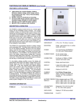
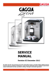
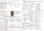
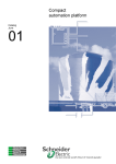
Atkinson Electronics, Inc.
TABLE OF CONTENTS
Features Diagram . . . . . . . . . . . . . . . . . . . . . . . . . . . . . . . . . . . . . . . . . 1
Charge Controller Display Kit
Description . . . . . . . . . . . . . . . . . . . . . . . . . . . . . . . . . . . . . . . . . . . . . . 2
PART NO. PVDM4LC/PVCM20D
Kit Contents . . . . . . . . . . . . . . . . . . . . . . . . . . . . . . . . . . . . . . . . . . . . . . 3
Operating and Installation Instructions
Description of Operation PVCM20D . . . . . . . . . . . . . . . . . . . . . . . . . . . 3
Description of Operation PVDM4-LC . . . . . . . . . . . . . . . . . . . . . . . . . . . 4
Installation Instructions for PVCM20D . . . . . . . . . . . . . . . . . . . . . . . . . . 5
Hookup Diagram for PVCM20D . . . . . . . . . . . . . . . . . . . . . . . . . . . . . . . 6
Installation Tips for PVCM20D . . . . . . . . . . . . . . . . . . . . . . . . . . . . . . . . 6
Installation Instructions for PVDM4-LC . . . . . . . . . . . . . . . . . . . . . . . . . 7
Battery Adjust Pot. and Jack Locations . . . . . . . . . . . . . . . . . . . . . . . . . 8
Installation Tips for PVDM4-LC . . . . . . . . . . . . . . . . . . . . . . . . . . . . . . . 8
Hookup Diagram for PVDM4-LC . . . . . . . . . . . . . . . . . . . . . . . . . . . . . . 9
User Instructions . . . . . . . . . . . . . . . . . . . . . . . . . . . . . . . . . . . . . . . . . 10
Features
Trouble Shooting Tips . . . . . . . . . . . . . . . . . . . . . . . . . . . . . . . . . . . . . 11
PVDM4-LC v
v
v
PVCM20D
v
v
v
In-line charge controller with temperature compensation, may
mount in DC breaker panel or in battery box
LED indication of solar charge and battery level status
Internal current shunt will handle up to 20 Amps @ 28V DC from
PV panels
Selectable operation: sealed/flooded batteries
Pulse action reduces battery sulfation
v
v
v
Fully automatic operation on 12V or 24V DC systems
Micro-controller for digital accuracy and reliability
Connect via RJ-45 jacks and Cat-5 network patch cable
v
v
Both Units
Light-switch sized module that can be surface mounted via cutout,
or electrical box mounted
Displays 4 battery functions: Battery voltage, Solar charge current,
Accumulated solar amp-hours, percent battery charge remaining
Back-lit LCD for reading in dim locations
NOTE: Read and follow these instructions before using this product.
Cleaning Tips . . . . . . . . . . . . . . . . . . . . . . . . . . . . . . . . . . . . . . . . . . . 12
Specifications PVCM20D . . . . . . . . . . . . . . . . . . . . . . . . . . . . . . . . . . 13
Specifications PVDM4-LC . . . . . . . . . . . . . . . . . . . . . . . . . . . . . . . . . . 14
Limited Warranty . . . . . . . . . . . . . . . . . . . . . . . . . . . . . . . . . . . . . . . . . 15
Template for PVDM4-LC . . . . . . . . . . . . . . . . . . . . . . . . . . . . . . . . . . . 16
Rev. 12/03
FEATURES DIAGRAM
PVDM4-LC
DESCRIPTION
PVDM4-LC
v Display Processor - Micro processor controls all display and
read-out functions.
v RJ-45 Jack - Power and signal connection point to PVCM20D
charge controller module. (Requires Cat-5 patch cable)
v Battery Voltage Adjust P1 - Displays battery voltage adjustment
potentiometer. (Set during step 2 of PVDM4-LC installation)
v Cable Error LED - lights when a crossover cable is connected.
v 3 Digit Backlit LCD Display - lights for 15 seconds every time the
select button is pressed.
v Mode Select Button - Allows user to change display read out,
reset solar amp hour accumulator, and lock display setting.
v Selection Indicators - Indicates which of 4 readings is displayed.
PVCM20D
PVCM20D
v Mounting Holes - accepts a #8 sheet metal or wood screw.
v 14" Yellow 14 awg. Wire - Connects to the + wire of the PV panel.
v 14" Red 14 awg. Wire - Connects to the + Battery terminal or wire.
v 16" Black 18 awg. Wire - Connects to the - Battery terminal or wire.
v Optional External Load Shunt Input - Used with PVDM6-LC display
unit. Input designed for 500 amp./50 mv load shunt.
v RJ-45 Jack - Power and signal connection point for the PVDM4-LC
display module. (Requires Cat-5 patch cable)
v Charge & Battery Status LEDs - Red charge status LED indicates
when charging. Battery charge level LEDs indicate: Full - Green,
Partial - Yellow, Low - Blinking Orange.
-1-
-2-
KIT CONTENTS
PVDM4-LC DESCRIPTION OF OPERATION
The PVDM4-LC display module serves as a remote digital readout for the
PVCM20D and PVDM6 for the PVCM40D charge controllers. The PVCM
charge controllers contain an internal solar current shunt, RJ-45 network jack
and associated internal wiring to provide power and signals to the PVDM4-LC
through a T568A or T568B standard computer network patch cable which plugs
into the RJ-45 jack on the back of the PVDM4-LC. If the wrong configuration
network cable, such as the crossover type, is used then the “error” LED on the
back of the PVDM4-LC will light indicating that the proper cable needs to be
plugged in for the display to work properly.
PVCM20D
PVDM4-LC
PVDM4-LC Mounting Screws
5' Cat. 5 Patch Cable
PVCM20D DESCRIPTION OF OPERATION
The PVCM20D micro-processor based photo-voltaic (PV) charge controller
connects PV panels to 12V or 24V DC storage batteries. The PVCM20D
determines which mode to operate in, 12V or 24V, by measuring both battery
and PV charge voltages. The PVCM20D performs five basic functions:
The PVDM4-LC’s normal display indication is battery voltage and its associated
LED. The select button allows the user to turn on the displays backlight,
advance to the next display setting, reset the solar and battery amp hour
accumulators, lock display or current setting, or activate scroll mode (see User
Instructions). The PVDM4-LC will automatically switch back to the battery
voltage display setting after 4 minutes unless the display setting lock is
activated. The backlight will come on for 15 seconds any time the select button
is pushed and will stay on continuously in scroll mode.
If a low battery voltage condition occurs, the display will automatically switch
back to the battery voltage setting (if not already there) and blink the display
reading and Battery voltage LED. If the user accesses other display settings
while in this condition, they will be displayed for 5 seconds then switch back to
battery voltage setting until the low battery voltage problem is corrected. Any
accumulated values may be meaningless if the battery voltage remains below
11V as this is the minimum voltage for the PVDM4-LC to operate properly. The
PVDM4-LC display will continue to accumulate amp-hours, they just won’t be
displayed without reverting back to the flashing battery voltage after 5 seconds.
The battery voltage signal tells the PVDM4-LC module what battery system
voltage it is: 12V, 24V or 48V.
1. Senses when the battery is fully charged and disconnects the PV charge
current to avoid over-charging the battery.
2. Resumes charging the battery when the battery voltage has dropped
sufficiently to accept additional charge current.
3. Checks the availability of PV charge current, by cycling the relay every
4 minutes. If there is insufficient charge current available, it will disconnect
the battery to prevent discharge through the PV panels at night.
4. It compensates for battery temperature and adjusts the charge threshold
voltages when mounted in battery case.
5. Its microprocessor reduces the charging rate of fully charged batteries to
minimize water addition requirements.
-3-
-4-
INSTALLATION INSTRUCTIONS (PVCM20D)
HOOKUP DIAGRAM (PVCM20D)
1. Complete the mounting installation of the Photo Voltaic Panel(s), verify and
label the + PV wire and - PV wire by measuring the PV voltage with sun light
applied to panel(s) if not already labeled. Now cover panel(s) with it’s
shipping box(es) to prevent PV panel output from being shorted during the
routing of the PV wiring to the location where the PVCM20D is to be
mounted.
2. If the PVCM20D is to be mounted somewhere other than next to the storage
batteries, a pair of 12 awg. wires (1 red, 1 black) may have to be pulled to the
PVCM20Ds mounting location from the battery compartment. Do not connect
either end of the pair of wires at this time.
3. Mount the PVCM20D with the screws provided. Do not remove the tape
covering the RJ-45 jack until you are installing the PVDM4-LC remote display
unit.
4. Now with the PV panel(s) covered and the pair of 12 awg. battery wires not
connected to the battery, it’s time to connect the PVCM20D wires.
5. First connect together the (-) negative wires from the PV panel, PVCM20D
(black) and black battery wires using a wire nut or butt splice (not provided).
Next connect the PV + wire and PVCM20D’s yellow wire together using a
wire nut or butt splice (not provided). Next connect the (+) Battery and
PVCM20D’s red (+) wires together using a wire nut or butt splice (not
provided).
6. Now at the battery box measure your battery voltage and note the voltage for
the next step. Next connect the black (-) wire to the (-) negative of the Battery.
Next connect the red (+) wire to the (+) positive of the battery.
7. The PVCM20D will power up, orange LED will light, then will blink or switch
to either yellow or green depending on the battery voltage. (Orange blinks
below 11.7V, yellow between 11.7V to 13.2V, green above 13.2VDC.)
8. Next remove the box(es) from the PV panel(s). If panel(s) are in the sun light
the PVCM20D will sense the PV voltage (16+V) and turn on the charge relay,
charging the storage battery(s). As the Battery voltage comes up the yellow
LED will switch to green LED @ 13.2V. When the Battery voltage reaches
14.2V the PVCM20D will stop charging the Battery until it is ready to accept
a charge again by either the battery falling below 12.7V @ 708 F), or an
ample load is applied to drop the battery voltage. (See PVCM20D
specifications for temperature reset voltages for charging on/off points.)
9. Replace the box(es) over the PV panel while the PVCM20D is charging and
watch for the red charge LED and relay to turn off. (Note: depending where
you are in the charge cycle it could be 4 minutes. The Charge controller only
looks at the PV voltage once every 4 minutes.)
10. Seal all connections with electrical tape, grease or silicone.
-5-
INSTALLATION TIPS (PVCM20D)
1. Exposed connections should be waterproofed. Grease or silicon will
adequately protect connections such as splices or the network cable jack.
Clip blue jumper wire for sealed battery threshold change.
2. When wiring the PV panel into the battery system, adequate wire size must
be used. 12 awg. or larger wire is recommended. If smaller wire is used,
the battery may not achieve full charge.
3. Check the battery fluid level occasionally (at least every 90 days) and add
water as necessary.
4. Install the PVCM20D in the battery enclosure for the temperature
compensation to work properly.
-6-
INSTALLATION INSTRUCTIONS (PVDM4-LC)
BATTERY ADJUST POT & JACK LOCATIONS
1. Complete the installation and test the operation of the PVCM20D charge
control module.
2. Before mounting the PVDM4-LC remove tape from the RJ-45 jack on the
PVCM20D and plug in the network cable to both the PVCM20D and PVDM4LC charge controller. Verify that all the readings work properly. Calibrate
the battery voltage reading by first measuring the battery voltage with an
accurate digital voltmeter. Adjust the PVDM4-LC's battery voltage reading
to match by adjusting the (P1) potentiometer (less than 1/4 turn), next to the
RJ-45 jack, on the back of the PVDM4-LC module. (See diagram to the
right.) Unplug the network cable on both ends.
3. Determine the mounting method to be used, surface-cutout or single gang
electrical box.
4. For surface-cutout mounting, place the template (found on page 16 of this
manual) over the desired mounting location and mark through the template
the two mounting screw locations. Drill two pilot holes into the cabinet or
mounting surface at the marked locations. Use a power drill to drive screws
into the mounting surface before mounting the display module. Back out the
screws, cut-out the template leaving the mounting screw tabs and attach the
template with the screws to the mounting surface. Draw around the template
on the mounting surface marking through the template around the mounting
screw tabs. Carefully cut out the marked area using a saber saw or router
leaving the mounting screw tabs.
5. Plug the network cable into the RJ-45 jack, after pulling it through the cutout
hole. Insert the screws through the front of the module and into the holes
and tighten by hand with a screwdriver. USING A POWER DRILL TO DRIVE
IN THE SCREWS THROUGH THE PVDM4-LC MODULE WILL VOID THE
WARRANTY BY DAMAGING THE PVDM4-LC MODULE!!!
6. For single gang electrical box mounting, mount the box securely and install
conduit (at least 3/4 in. EMT) as desired. Route or pull the display end of the
network cable into the electrical box being careful not to damage the RJ-45
plug. Plug the network cable into the back of the PVDM4-LC module and
mount the module with 6-32 screws into the tabs of the single gang box.
Hand tighten the screws to avoid damaging the PVDM4-LC module.
7. Now plug the charge controller end of the network cable into its RJ-45 jack
and verify that the display is working properly. Use grease or silicone to
cover the controller side of the network cable plug to avoid corrosion and fill
the end of conduit.
-7-
The Battery voltage calibration potentiometer is located in the lower left hand corner
of the PVDM4-LC below the RJ-45 jack, along with a cable error LED.
INSTALLATION TIPS (PVDM4-LC)
1.
If a network cable (up to 50 feet long), other than the one supplied in this kit, is
used to connect the PVDM4-LC to the PVCM20D charge controller, it must be
the same “straight through” type or the display will not read properly. A “cable
error” LED may light up on the back of the meter if the wrong type of cable such
as the “crossover” type is used.
2.
The minimum solar charge current the PVDM4-LC will indicate is about .20
amps. Below this value the PVDM4-LC will display “chr” if the PVCM20D is
passing solar charge current to the battery. The current display will indicate “0"
if the controller is not charging.
3.
The solar current shunt used in the PVCM20D in this kit is for a maximum of 20
amps. There are other meters and charge controllers in the Atkinson Electronics
product line. Only charge controllers and meters from this PVDM4-LC/
PVCM20D kit may be interchanged with other controllers and meters from kits
of the same part number.
-8-
HOOKUP DIAGRAM (PVDM4-LC)
USER INSTRUCTIONS
1. The power and signals to the PVDM4-LC display are supplied through the
CAT-5 network cable connecting the PVDM4-LC to a PVCM20D charge
controller or PVDAM adaptor module.
2. The PVDM4-LC will normally revert back to the continuous battery voltage
display after approximately 4 minutes in any other reading.
3. "Select" button operation:
a. “Tapping” or pressing the “select” button activates the backlight for 30
seconds.
b. Pressing for ½ to 1 second then releasing the button advances to the
next reading.
c. From the battery voltage display only, pressing and holding the button
will advance the display automatically through each of the readings.
1) If the button is released before returning to the battery voltage
display, the reading will remain in that position until the display times
out (4 minutes).
2) If the button is held through all readings then released at the battery
voltage display, the PVDM4-LC will enter the scroll mode, advancing
to the next reading every 3 seconds, indefinitely.
3) “Tapping” the button exits the scroll mode.
4) A low battery voltage condition will also exit the scroll mode.
d. Display lock mode is available for Solar Charge Amps and Battery
Percentage.
1) To lock display from timing out and reverting to battery voltage,
advance display to desired position then press and hold the button
until the display flashes (approximately 3 seconds).
2) Release button when the display stops flashing, it will remain
indefinitely in that reading.
3) “Tapping” the button while the display is flashing prevents entering
the lock mode.
4) Advancing to the next reading (see par. 3b) cancels the lock mode.
5) Low battery voltage also cancels the lock mode.
e. Resetting the Solar Accumulated Amp Hour reading to zero.
1) Pressing and holding the button for approximately 6 seconds will
reset the display value. The display starts flashing after 3 seconds,
the reading goes to zero after 6 seconds and the display stops
flashing.
2) Releasing the button while the display is flashing cancels the reset.
The display will stop flashing and retain its current value after
several seconds.
3) Note: There is no display lock for the accumulation displays. They
will revert to battery voltage after approximately 4 minutes.
4. Low battery voltage will cancel any user selections. The user can advance
to any reading, but it will automatically return to the flashing low battery
voltage display after 5 seconds.
-9-
- 10 -
TROUBLE SHOOTING TIPS
Problem
Solution
-
Module doesn’t click on and there is sunlight on the PV panels.
Verify that the battery voltage is less than 12.75V (or 25.5V on
a 24V DC system) and that the open PV voltage is greater
than 16V or (32V). If both conditions are met, wait for 4
minute delay period.
Problem
Solution
-
Module clicks every several minutes.
This is the normal operating sequence.
Problem
-
Solution
-
Module charges for a few seconds then shuts off for 4 minutes
or longer.
The batteries are fully charged and the charge current was at
maximum output.
It may also mean that the batteries have a poor connection or
a bad cell with high internal resistance.
Problem
-
Solution
-
Problem
-
Solution
-
CLEANING TIPS
Do not apply water or cleaning solution directly to the face plate or LCD of the
PVDM4-LC. The liquid could run between the face plate and the LCD causing
damage to the electronics and void the warranty.
Recommendation for cleaning PVDM4-LC: apply water or cleaning solution
to a soft cloth and spot clean the face plate as needed.
Module switches on for 1 or 2 minutes and then is off for a
much longer period of time.
This is also normal if the battery is at or nearly fully charged
and the PV charge current is at or near maximum.
The battery load has been left on and the storage battery has
discharged below 6V DC. The PV system is not charging when
the load is turned off.
The PVCM20D needs at least 6V DC from the battery to
operate properly. Place panel in direct sunlight and jumper the
red and yellow wires for a few minutes, thus bypassing the
charge controller allowing the battery voltage to rise to at least
7V DC. Disconnecting the jumper will allow the PVCM20D to
charge the battery up to normal levels.
- 11 -
- 12 -
PVCM20D SPECIFICATIONS
PVDM4-LC SPECIFICATIONS
SIZE/WEIGHT:
2.1 x 4.0 x 1.3 inches, 6 ounces
SIZE/WEIGHT:
2.75 x 4.5 x .75 inches, 3 ounces
ENCLOSURE:
Epoxy potted in PVC plastic
MOUNTING:
Single - gang electric box or surface mount with cutout
MOUNTING:
POWER:
2 #8 x .75" L screws
6 to 30V DC from storage battery
POWER:
12 to 24V DC from PVCM20D or
12 to 48V with PVDAM adaptor
LOAD CAPACITY:
20 Amps @ 28V DC
(Minimum is 20 watt panel)
CURRENT DRAW:
15 mA normal mode
35 mA with back light on
TEMPERATURE
COMPENSATION:
Flooded Battery Thresholds:
below 08C
On @ 13.3VDC
between 0-58C On @ 13.3VDC
between 5-108C On @ 13.1VDC
between 10-158C On @ 12.9VDC
between 15-308C On @ 12.7VDC
between 30-358C On @ 12.7VDC
between 35-408C On @ 12.6VDC
between 40-458C On @ 12.6VDC
Temps > 458C On @ 12.7VDC
CONNECTION:
RJ-45 jack to T568A or T568B network Cat-5 patch cable
CONTROL:
Single select/reset button
DISPLAY:
3 digit LCD to 999 or 99.9 with decimal
.35 inch character height
VOLTAGE:
Displays 0 to 60V DC
Off @ 15.0VDC
Off @ 14.8VDC
Off @ 14.6VDC
Off @ 14.4VDC
Off @ 14.2VDC
Off @ 14.0VDC
Off @ 13.8VDC
Off @ 13.6VDC
Off @ 14.2VDC
Sealed Battery Thresholds: *Blue Jumper Clipped *
Voltages are 0.3VDC less than above threshold voltages.
Rm temp 20-258C
On @ 12.4VDC Off @ 13.9VDC
Double above threshold values for 24V DC systems.
ACCURACY:
6 0.1V DC (12V System) 6 0.2V DC (24V System)
CURRENT DRAW:
Continuous - [7mA
During charge - [ 55mA
LED INDICATION:
Charging Mode
Battery Voltage
Red
Green ] 12.75V DC or 25.5V DC
Yellow 11.2V DC to 13.3V DC or 22.4V DC to 25.5V DC
Orange [ 11.2V or 22.4V
VOLTAGE DROP:
0.10V DC @ 20 Amps
MINIMUMS:
Charge current - 80mA
Open PV Voltage - 16V or 32V DC
INTERNAL SHUNT:
.005 V, 100 millivolt @ 20 Amps
TEMPERATURE:
-30 to 758 C
RELAY LIFE:
100 million mechanical operations
- 13 -
CURRENT
DISPLAY:
0 to 20 Solar Charge Amps
(below .25 amps the display will indicate “chr”
if the controller is charging)
BATTERY PERCENT
DISPLAY:
While charging reads over 100%
12.8V = 100%, 10.8V = 0%, 12V system
25.6V = 100%, 21.6V = 0%, 24V system
51.2V = 100%, 43.2V = 0%, 48V system
LOW BATTERY
VOLTAGE:
Detects @ 11.2V, 22.4V & 44.8V
for 12V, 24V & 48V systems
AMP-HOURS:
Displays 0 TO 999 accumulated
TEMPERATURE:
0 to 508 C
- 14 -
LIMITED WARRANTY
LIMITED WARRANTY
Atkinson Electronics, Inc. gives this express warranty (along with extended warranty
endorsements, where applicable) in lieu of all other warranties, express or implied,
including (without limitation), warranties of merchantability and fitness for a particular
purpose. This constitutes Atkinson Electronics, Inc.'s sole warranty and obligation with
regard to our products as well as the Customer's sole remedy.
4.
Atkinson Electronics, Inc. will not accept responsibility for any invoiced goods or
services that are not covered by an Atkinson Electronics, Inc. written purchase
order. Under no circumstances does Atkinson Electronics, Inc. agree to pay for
labor or other related expenses associated with the troubleshooting and/or repair
of our product without prior specific written authorization.
Atkinson Electronics, Inc. expressly disclaims all liability and responsibility for any
special, indirect or consequential damages or any further loss of any kind whatsoever
resulting from the use of our product. The Customer's sole and exclusive remedy and
the limit of Atkinson Electronics, Inc.'s liability for any loss whatsoever, shall not exceed
the purchase price paid by the Customer for the product to which a claim is made.
5.
Information in our descriptive literature is based on product specifications that are
current at the time of publication. Product specifications, design and descriptive
literature are subject to change as improvements are introduced. Although we
announce changes as they occur, we cannot guarantee notification to every
Customer. Atkinson Electronics, Inc. warrants delivered products to conform to the
most current specifications, design and descriptive literature.
Countries or States that do not allow limitations of incidental or consequential damages
or on how long an implied warranty lasts, the above limitations may not apply to you.
This warranty gives you specific legal rights and you may also have other rights which
vary from State to State or Country to Country.
All products manufactured by Atkinson Electronics, Inc. are warranted to be free from
defects in material and workmanship in accordance with and subject to the following
terms and conditions:
1.
This warranty is limited to the original customer only. It cannot be transferred or
assigned to third parties unless the intent to transfer to a third party is expressly
indicated in a purchase order and/or warranty processing arrangements have been
agreed upon in writing by Atkinson Electronics, Inc.
2.
Atkinson Electronics, Inc. will correct any defects in material or workmanship which
appear within two (2) years from the date of shipment by Atkinson Electronics, Inc.
(or its authorized distributors) to the original Customer. Atkinson Electronics, Inc.
will repair or replace, at our option, any defective products, provided that our
inspection discloses that such defects developed under normal and proper use.
This warranty does not extend to goods subjected to misuse, neglect, accident or
improper installation, or to maintenance or repair of products which have been
altered or repaired by anyone except Atkinson Electronics, Inc., unless otherwise
stated in writing.
This warranty policy may be expanded or limited, for particular categories of products
or Customers, by information sheets published as deemed appropriate by Atkinson
Electronics, Inc.
TEMPLATE (PVDM4-LC)
Atkinson Electronics, Inc. will correct any defects in material or workmanship of
OEM products (designated as such in our catalog or web site) which appear within
two (2) years from the product date code or from the factory invoice date,
whichever is later.
3.
An appropriate charge (25% of product list price) may be made for testing, repairs,
replacement and shipping for a returned product which is not defective or found to
be defective as the result of improper use, maintenance or neglect.
-Cut out of booklet-
- 15 -
- 16 -