1
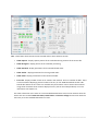
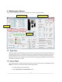
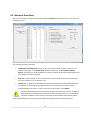
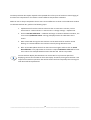
Dealer4
PC Software
User
Manual
Service
Software
Manual
ver:ver:
1.11.2
1. Introduction .................................................................................................. 3
Introduction................................................................................................................................2
2.1 Main
Menu ................................................................................................... 4
2.1.
Main Menu window.................................................................................................4
Summary of additional functions.................................................................................................3
2.2.
Board Set statistics...................................................................................................6
2
Installing
the Service
Software ....................................................................................................4
3.3 File
command
group......................................................................................
7
3.1.
New command.........................................................................................................7
Read Service File function ...........................................................................................................5
3.2.
Load command ......................................................................................................10
Save command
53.3. Maintenance
Screen ......................................................................................................11
...................................................................................................................7
3.4.
Exit command ........................................................................................................12
4
5.1
Gates Test ..........................................................................................................................7
4. Deal command ............................................................................................ 13
4.1.
with the Dealer4 machine.............................................................13
5.2 Communication
Focus Check .......................................................................................................................7
4.2.
Deal function description .......................................................................................14
5.3
Enlarge picture...................................................................................................................8
4.3.
Dealing boards.......................................................................................................18
4.4.
multiple
copies
of the same board .............................................................1910
5.4 Dealing
Advance
Functions
...........................................................................................................
4.5.
Dealing a Subset of the Board Set...........................................................................19
5.4.1 Errors counting............................................................................................................. 11
4.6.
Dealing Errors ........................................................................................................19
Board
number
checking.
........................................................................................2013
64.7. Display
Control
Screen
..............................................................................................................
5. Read command ........................................................................................... 23
6. Edit command ............................................................................................. 25
6.1.
6.2.
Board Set Editing ...................................................................................................26
Current Board Editing.............................................................................................28
7. Analyze ....................................................................................................... 31
7.1.
7.2.
Basic description....................................................................................................31
Possible errors during analysis. ..............................................................................33
8. Print command ........................................................................................... 34
Version information:
8.1.
Print Hands Record to printer.................................................................................34
Ver
1.0: Initial
issue :Hands
02/08/2013
8.2.
Print
Record to the text file..........................................................................43
8.3.
Print Score Cards....................................................................................................45
Ver 1.1 added features for version 4.70 issued: 30/10/2014
__________________________________________1_________________________________________
__________________________________________1_________________________________________
1 Introduction
This manual describes the Service version of the PC Dealer4 software. The Service Software is intended
for technicians and has additional functions useful during diagnostics and setup.
The Service Software should not be given to the customer.
This manual describes version 4.70 of the Service Software. New features in version 4.70 are:
•
Display recent errors counts
•
Service functions for Display Control
In this manual the following signs are used to highlight important information:
Critical information for safety and proper operation of the Dealer4 machine. Always read
and folow.
Warnings.
Additional important information.
__________________________________________2_________________________________________
2 Summary of additional functions
The Service Software has all functions of the standard software, however it also has additional functions,
most of which can be found in the Maintenance window. These are:
•
Read Service File
•
Gates Test
•
Focus
•
Enlarge card picture view
•
Set Number of Dealt Boards
•
Errors List display
•
Set Hardware ID
•
Set Serial number
•
Set Manufacture Date
For Display Control Screen additional functions are:
•
Format Dealer4+ Internal Memory
•
Dealer4+ RTC calibration
__________________________________________3_________________________________________
3 Installing the Service Software
The Service Software is distributed as a single exe file - Dealer4.exe. To install it please do following
steps:
•
Install the standard Dealer 4 Software Version 4.70 on the computer.
•
Download Dealer4.exe file from www.dealer4.com/Beta_versions/Service4v70/Dealer4.exe
•
Replace existing Dealer4.exe with the downloaded file. The Dealer4.exe file is located in
C:\Program Files\Dealer4 directory (or C:\Program Files (x86) for 64 bit Windows version). To
replace the exe file it may be required to login as an administrator.
Starting the Dealer4 Software will now open the Service Software. Any shortcuts or link from the desktop
will continue working normally. The Main Menu screen is the same as the normal version expect the
notification in the bottom left corner as shown below:
Do not run Dealer4.exe from any location other then original one in the Program Files
folder. Running from any other location will cause malfunction or crash the program.
__________________________________________4_________________________________________
4 Read Service File function
The Read Service File function will show all the information received from a user via the Service File.
Service Files contain all the information usually displayed on the Maintenance Screen and some
additional information which makes is possible to remotely diagnose problems with a machine.
Read Service File function can be entered from Main Menu. Click on Maintenance then on the Read
Service File:
Then the standard file dialogue box will appear. Choose the Service File to be opened and click Open.
The file will be read and convert into the screen similar to the Maintenance screen but because it is not a
"real" Maintenance screen most of the controls will not work. This screen is only used to read the Service
File information not control a machine. There are also few additional features and controls compared to
the standard Maintenance screen:
__________________________________________5_________________________________________
Info - information when Service File was created and on which software version
•
Show Capture - display capture picture of the card taken during creation of the service file
•
Show Recognize - display picture of the card after processing
•
Show Standard - display parameters for the Standard Card Index
•
Show Jumbo - display parameters for the Large Card Index
•
Show Small - display parameters for the Small Card Index
•
Errors list - display number of each error stored in the machine. Error 0 is number of deals. There
are three columns displaying overall number of errors, for last 1000 boards dealt and for 100
boards deal. Recent errors counts are available only for firmware 3.10. If Service File was done
using earlier firmware these columns display all zeros. (Like on the example above). For more
information see chapter 5.4.
The other information is the same as on the standard Maintenance screen at the moment when the
Service File was created. Draw Start Point, Draw frames and Picture enlarge functions will work the
same way as on the standard Maintenance screen.
__________________________________________6_________________________________________
5 Maintenance Screen
There are few additional functions on the Maintenance Screen in Service Software:
Enlarge picture
Advance Functions
Gates Test
Focus Check
5.1 Gates Test
Gates Test, when checked will open and close all gates. This function can be used to test gates for an
extended period of time - for example when there is a problem with gate which happens only after a
hundred boards are dealt or once when machine becomes warm. It also can be used to check gate
operation by listen to the "clicking" sound. The number on the right of checked box shows how many
times gates are opened or closed.
5.2 Focus Check
Focus Check function is used to check the focus of the camera. A Focus score is calculated every time
Capture is clicked. To set the focus perform following procedure:
•
Put 10 of spade or club in the feeder.
•
Check Camera LEDs and Camera Power boxes.
__________________________________________7_________________________________________
•
Be sure that Start Point is inside the symbol - if not perform Auto Setup first
•
Click on Capture. In the Focus window the number will appear. The number represents the
focus of the camera and can be from 100 (perfect focus) to 0 (no focus at all).
•
Rotate lens of camera and click Capture again
•
Repeat this procedure until value between 90 and a 100 will be obtained. For older
machines when lens is "used" it is allowed to have focus value down to 80 - the machine still
will be working correctly. Anything below required lens to be replaced.
If lens is dirty - proper focus cannot be set - clean the lens first. If cleaning does not help it means
that lens might be damaged (scratched) and should be replaced.
It is not required to click Show during focus setup procedure. Clicking on Capture is
enough to update focus value.
Tightening the lens locking screw may change the focus - usually making it worse. If this
happens, unlock the screw, turn the lens 1/8 of the turn and tighten it again.
The recheck the focus. Repeat this procedure until a satisfactory value is obtained.
Focus value depends on quality of the card used. Use only new card with sharp prints
when checking the focus.
5.3 Enlarge picture
By clicking on the card picture it is possible to see an enlarged version of it. It will open in the new
window shown below:
__________________________________________8_________________________________________
There are some controls on the top right corner - Raster will display pixel outlines, Refresh will
redraw the picture and Brightness shows the pixel value at the X, Y position. Highlight function
shows on blue all pixels with brightness value between From value and To value. It is useful for
advance analysis of the card recognition problem but is rather for development team then the
service technician.
To return to the Maintenance screen - close this window by clicking on the control in the top right
corner.
__________________________________________9_________________________________________
5.4 Advance Functions
The rest of the Service functions are available under the Advance button. Clicking on it will open the
following window:
The following functions available:
•
Set Number of Dealt Boards - Resets or sets the number of boards dealt. To do this, first
change the number in the Boards Dealt window and the click on Set Number of Dealt
Boards. This function is used to update the number of dealt boards when replacement of the
main electronic board is required.
•
Errors list - shows number of errors stored in the machine. Refer to Software User Manual
for more information on a particular error.
•
Parameters - includes Serial Number of the machine, Manufacturing date and Hardware ID.
Parameters can be changed by typing new number in the particular text box or check /
uncheck Hardware ID option. To store new values into machine - click Update.
Correctly setup Hardware ID is essential for proper operation of the machine. As with all
other parameters, Hardware ID is stored in the main electronic board - so if this board is
replaced - Hardware ID have to be set according to the hardware requirements. More
details about Hardware ID setup will be available in the Dealer4 Electronics Service Manual.
__________________________________________10_________________________________________
5.4.1 Errors counting
In version 4.70 of the PC software and firmware 3.10, a more sophisticated errors counting system was
introduced. It shows not only the overall number of particular errors but also the number of errors which
occurred for last 1000 and 100 correctly dealt boards. This shows if errors happened recently (thus
indicating a problem which needs to be fixed) or if they are “old” errors which are not causing any
problems right now.
There are three columns in the Error window. The first, shows the overall number of errors (Error 0 is
number of correctly dealt boards). The second column shows the number of error for last 1000 correctly
dealt boards and third column – for last 100. Analyzing these values can give information about the
current condition of the machine:
In the above example Error 5 (which is Extra Card in S) happened 48 times in last 100 boards so every
second board dealt. This indicates that in is a recent problem with the South Gate which has to be fixed.
On the other hand Error3 happened only once for the last 1000 boards – so this is not an issue now.
Error 25 overall happened 418 times per 43549 boards dealt so the ratio is around 1/100 which is
maintained for last 1000 and 100 boards – this should be treated as normal.
Error 0 which is number of boards dealt for second column shows always 1000 and for third column
shows always 100 unless the machine has dealt then less 1000 or 100 boards. This will happen for new
machines or for machines which have recently been updated to firmware 3.10.
__________________________________________11_________________________________________
If second and third column shows all zeros – machine has a firmware earlier then 3.10 and recent errors
are not counted.
For error descriptions see Dealer4 Software User Manual Appendix B.
__________________________________________12_________________________________________
6 Display Control Screen
The Display Control screen for the Service version of Dealer4 PC software version 4.70 is shown below:
Service version additional
functions
The service version has two additional functions:
•
Format Internal Dealer4+ memory
•
RTC calibration
The Format Internal Memory option erases all information in the Dealer4 memory and formats it to the
original state. It can be used if this memory is corrupted for any reason or causing any problems. Internal
Memory works similar to a USB Flash drive. It is protected against unexpected events like power loss
during write etc. however over time errors can accumulate (just like any PC disk drive) which can end up
causing a loss of capacity or other problems with reading/writing files. To restore it to the original state,
the format function will have to be used.
The Real Time Clock which is built into Dealer4+ machines has an accuracy of around 1s per 24h. To
maintain this accuracy, a calibration function is available. Calibration is always performed during
__________________________________________13_________________________________________
machine production but maybe required to be repeated after a few years of use due to natural aging of
the electronic components or if machine is used in different temperature conditions.
Dealer4+ time is always compared to the PC time. Current difference is shown in the calibration window.
To calibrate Dealer4+ RTC, perform the following steps:
1. Update PC time from the internet to be sure that it is accurate. To do this, click on
Control Panel -> Date and Time -> Internet Time -> Change settings -> Update now
2. Click on Start RTC calibration – calibration will begin. In the RTC calibration window , the
current state (Calibration status: running) is displayed. Also the calibration time is
shown.
3. Wait at least 48h. During this time machine can be switched off or used for normal
dealing. It is recommended to use machine normally during calibration time.
4. After at least 48h update the PC from the internet time again and then click on Finish
RTC calibration. If any adjustment to the clock is required Calibration value will be not 0.
If this value is for example 9740 that means that RTC will add 1s every 9740s.
Current Dealer4+ display firmware does not use the RTC for any function apart from
displaying current time and date on the Front Display. Therefore, having accurate time is not
important for Dealer4+ operation. RTC will be used in the future especially when writing to a
Flash Drive will be implemented.
__________________________________________14_________________________________________


![SpeedAngle SA to KML Converter User Manual [April 2013]](http://vs1.manualzilla.com/store/data/005858940_1-650ff431a5d53db72218f3209001fa9f-150x150.png)