1
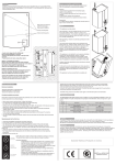
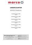
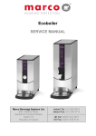
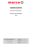
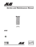
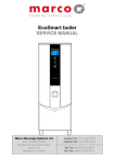
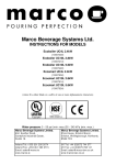
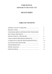
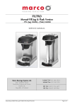
Ecoboiler WMT5 Ecoboiler WMPB5 Ecoboiler WMT3 Ecoboiler WMPB3 SERVICE MANUAL Marco Beverage Systems Ltd. 63d Heather Road, Sandyford Industrial Estate, Dublin 18, Republic of Ireland Ireland Tel: (01) 295 2674 Ireland Fax: (01) 295 3715 UK Tel: (0207) 274 4577 UK Fax: (0207) 978 8141 CONTENTS: PAGE 1. INTRODUCTION 3 2. SAFETY INSTRUCTIONS 3 3. BASIC INSTRUCTIONS 4 3.1. 3.2. 3.3. 3.4. 3.5. 3.6. 3.7. 3.8. Installation Details Operation Calibration Troubleshooting Maintenance Cleaning Limescale Cautions and Safety Tips 4. 4 4 5 5 5 6 6 6 TECHNICAL DATA 4.1. 4.2. 4.3. 4.4. 4.5. 4.5.1. 4.5.2. 4.5.3. 4.6. 4.7. 4.8. 4.9. 4.10. General Description External Arrangement Internal Arrangement Access to internal components PCBs PCB Layout PCB Ecoboiler Control – 1600345 PCB Ecoboiler Display 10L – 1600349 Troubleshooting – Diagnostic guide Tank Components Descaling procedure Wiring Diagram 1000671 Ecoboiler WM5 Spare Parts List Service Manual Ecoboiler wallmount 1000671 100676 061010 6 7 7 8 9 9 10 11 11 14 15 16 18 Page 2 of 18 1. INTRODUCTION: The information provided in this manual is intended to assist in the installation and maintenance of the Marco Ecoboiler Wallmount Range. Please read the instructions carefully to prevent accidents and ensure an efficient installation. This manual is not a substitute for any safety instructions or technical data affixed to the machine or its packaging. All information in this manual is current at the time of publication and is subject to change without notice. Only technicians or service providers authorised by Marco should carry out installation and maintenance of these machines. Marco accepts no responsibility for any damage or injury caused by incorrect or unreasonable installation and operation. 2. SAFETY INSTRUCTIONS: Read all instructions. Do not operate any appliance with a damaged cord, plugs, or after the appliance malfunctions or has been damaged in any manner. Switch off at the mains (unplug or disconnect from outlet) and turn off the water supply when not in use and before cleaning. Allow to cool before removing components. The use of spares and accessories not recommended by Marco may cause damage and/or injuries. Do not use outdoors. Do not place on or near a hot gas or electric burner. Do not use the appliance for anything other than its intended use. Save these instructions. Service Manual Ecoboiler wallmount 1000671 100676 061010 Page 3 of 18 3. BASIC INSTRUCTIONS: 3.1. INSTALLATION DETAILS: Electrical installation: o 2.4kW o Suitable cabling and fusing for a 2.4-3 kW circuit. o Ensure the machine is fully earthed. Plumbing installation procedure: Note: Marco recommend that this machine be positioned over a counter with a drainage facility. Marco cannot be held responsible for any flood damages. Mains water pressure required (limits): 5-50psi (35-345kPa) Fit a stop Valve on a cold water line and attach a 3/4" BSP male fitting, (e.g. 3/4" x 1/2" 311 or washing machine type stop valve). Connect straight tailpiece of the inlet hose to the stop valve fitting. Make sure that the preattached sealing washer is fitted. Turn on the water to flush any impurities, dust etc from the inlet hose and water pipe. Allow several litres through. Connect the hose to the inlet valve of the boiler (again 3/4" BSP). The orientantion of the tail piece will vary depending on whether machine is plumbed at the rear or at the underside. o When the machine is plumbed from the rear , connect right-angled tailpiece to the inlet valve of the boiler (again ¾” BSP) o When the machine is plumbed from the underside , connect non-angled tailpiece to the inlet valve of the boiler (again ¾” BSP). Make sure the sealing washer is fitted here also. Turn on water and check for leaks. 3.2. OPERATION: Check that all installation procedures have been carried out. Ensure water valve is on and there is power to the appliance. The “Ready/Status” light will cycle two red flashes while the machine is filling to the safe level. After this amount of water has heated to about 96ºC the boiler will draw more water in until the temperature drops by 1 or 2 degrees. The boiler will then heat again. This heat fill cycle continues until the boiler is full. Whilst the machine is above the safe level and filling, the “Ready/Status” light will remain blank. The “Ready/Status” light will glow green when the machine is both full and up to normal operating temperature. The boiler is now ready for use. NOTE: Because the boiler is electronically controlled no priming is necessary. The element cannot switch on until a safe level of water is reached. Service Manual Ecoboiler wallmount 1000671 100676 061010 Power Button Ready/Status Indicator Ecomode Button Page 4 of 18 3.3. CALIBRATION The Ecoboiler control PCB (1600345) has the ability to have the desired set-point temperature at whatever setting is required. During manufacture of the PCB it is set to the default temperature of around 95°C. If the temperature setting needs to be modified on-site please follow the steps below: 1. To Enter Calibration mode: a. Turn the machine off at the mains power supply. b. Then, whilst depressing the tactile switch on the PCB, turn the mains power back on. c. All available LED’s on the front panel will now blink continuously. d. The machine is now in Calibration mode. 2. In Calibration Mode the machine will heat continuously until the tactile switch on the PCB is pressed for a second time (NB: The tactile switch should be pressed for at least 1 second) 3. Using a thermometer to measure the temperature at the thermistor pocket, the machine should be allowed to reach the desired set-temperature. (NB: It may be necessary to let the unit cool down if the desired set point is lower than the units current temperature) 4. Following a correct calibration procedure the tank temperature should be maintained within 3°C of the desired set-point temperature. In the event of an incorrect calibration process the steps below should be followed: 5. If the tactile switch is pressed too early and the temperature is set lower than desired, the tester should simply repeat calibration. 6. If the tactile switch is pressed too late and the set temperature is too high, the tester will need to wait for the temperature in the tank to cool, or add cool water, and then repeat calibration. 3.4. TROUBLESHOOTING The Ready/Status light signals various errors or problems. A cycle of red flashes indicates an error. The number of flashes in a cycle corresponds to the symptom in the table below: Status/Diagnostic light guide: No of Symptom flashes Action required 2 Water level below elements. Normal when machine first fills. Check water pressure , if this is OK then call service agent. 3 Temperature sensor failure (o/c) Call service agent 4 Water not heating Call service agent 5 Temperature sensor failure (s/c) Call service agent 6 Machine not filling Check water pressure. If OK – switch machine off and on again. If problem reoccurs - call service agent. Note: Some of the error sequences w ill be displa yed if there is low water pressure. Please chec k that there is w ater pressure and that the w ater stop valve is open before calling your service agent. 3.5. MAINTENANCE: Marco machines have been designed to give many years of trouble free service. Marco Beverage Systems manufacture and test to ISO9002:2000 standard. The only regular maintenance required is occasional de-scaling. Service Manual Ecoboiler wallmount 1000671 100676 061010 Page 5 of 18 3.6. CLEANING: The exterior of these machines may be cleaned with a damp cloth and a light detergent. Do not use abrasive cloths or creams, as this will spoil the finish of the machine. Do not use a water jet or spray. Beware of accidentally operating the draw off tap or push button when cleaning the front of the machine. 3.7. LIMESCALE: In common with all water boiler manufacturers, service calls resulting from limescale are not covered by warranty. Fitting a scale reducer is recommended, especially in hard water areas. This can reduce the build-up of scale but may not stop it altogether. The frequency that descaling is required depends on the local water supply; hard water areas need more attention. A scale reducer can reduce the build up of scaling, but may not stop it altogether. Descaling of the machine should ideally be carried out by qualified service personnel. 3.8. CAUTIONS AND SAFETY TIPS: This appliance must be earthed. Risk of flooding. The hose supplied with this unit is non-toxic food quality tested to 190psi. However, a hose is not a permanent connection. It is, therefore, advisable to switch off boiler and close the stopcock valve when boiler is not in use, e.g. overnight, weekends etc. Risk of scalding. Beware of accidentally operating the water draw off tap especially when cleaning the front of the boiler. The utmost care has been taken in the manufacture and testing of this unit. Failure to install, maintain and / or operate this boiler according to the manufacturer’s instructions may result in conditions that can cause injury or damage to property. If in any doubt about the serviceability of the boiler always contact the manufacturer or your own supplier for advice. 4. Technical Data: 4.1. GENERAL DESCRIPTION: Dimensions Performance Electrical Plumbing ECO Boiler WMT3, WMPB3, WMT5, WMPB5 WMT3 WMPB3 WMT5 Height (mm) 447 447 447 Width (mm) 325 325 325 Depth (mm) 222 222 222 Immediate Draw-Off (litres) 5.6ltr 5.6ltr 5.6ltr Max. Hourly Output 24ltr 24ltr 24ltr (litres/hour) Connection 2.4kW, 230V. Fittings 0.75” BSP Pressure Food grade inlet hose supplied 5-50 psi (35-345 kPa) Service Manual Ecoboiler wallmount 1000671 100676 061010 WMPB5 447 325 222 5.6ltr 24ltr Page 6 of 18 4.2. EXTERNAL ARRANGEMENT: Top tank access Lid Side Panel Fixed centre panel Tap/ Push Button 4.3. INTERNAL ARRANGEMENT: PCB Ecoboiler Control (1600345) High Level Probe Assembly (2300463) PCB Bracket Mid Level Probe Assembly (2300463) Terminal Mains Connector 1502011 Thermal Switch 130Deg (1502087) Valve inlet Solenoid (1502190) Overflow TuberHose Low Level Probe Assembly (2300463) Thermistor Pocket U Shape 2300765 Service Manual Ecoboiler wallmount 1000671 100676 061010 ELEMENT 2.4kW 230V 1500950 Page 7 of 18 4.4. ACCESS TO INTERNAL COMPONENTS: ANY MAINTENANCE WORK ON ANY sECOBOILER PRODUCT SHOULD ONLY BE CONDUCTED BY A TRAINED SERVICE ENGINEER. Removal 1. Disconnect the machine from the 2. 3. 4. 5. electrical supply. Allow to cool sufficiently. The removable Side Panels are fixed at the top of the machine. Unscrew with a Philips head screwdriver. Remove the panels in an upward and outward motion. Reassembly To re-attach the side panels, complete the removal actions in steps 4 & 5 in reverse order. Ensure that the panel screws are securely fastened. 6. Reassembly 7. 8. To re-attach the side panels, complete Service Manual Ecoboiler wallmount 1000671 100676 061010 the removal actions in steps 4 & 5 in reverse order. Ensure that the panel screws are securely fastened. Page 8 of 18 Inlet Solenoid Access: To access the inlet solenoid, Unscrew the two crossrecessed pan headed screws holding the bracket in place. 4.5. PCBs: 4.5.1. PCB Layout: Internal PCB Layout: PCB Ecoboiler Control (1600345): Controls the heater switching Controls the water inlet switching Controls tank temperature/temperature adjustment PCB Ecoboiler Display 10L (1600349) consists of: Power On/Off button Power On LED Status/Ready LED ECO Mode On/Off Button ECO Mode On LED PCB Ecoboiler Display 10L (1600349) PCB Ecoboiler Control (1600345) Service Manual Ecoboiler wallmount 1000671 100676 061010 Page 9 of 18 4.5.2. PCB Ecoboiler Control: 8 9 10 7 11 6 6 12 5 13 4 14 3 15 2 19 1 19 16 17 18 COMPONENTS OF PCB ECOBOILER CONTROLLER 2008: 1. Dispense Solenoid Tab 2. Inlet Solenoid Tab 3. Neutral Tabs 4. Transformer 5. Mains Live In Tab 6. Relays - Heater Switch the element 7. Heater Tab 8. On/Off 2-way Connector Short circuited on this Ecoboiler machines – power switch controlled through the display PCB 9. LED 5-way Connector 10. Earth Tab 11. Daughter PCB Connector (low voltage) Service Manual Ecoboiler wallmount 1000671 100676 061010 Page 10 of 18 Connects to Daughter PCBs – allows switching of more than one element 12. External Connector 13. Thermistor Connector 14. Dip Switch – 3 way Allows selection of software for specific machine 15. Tactile Switch For use during calibration procedure (refer to Calibration in Sec 3.3) 16. Water Level – 5-way connector (low voltage) Connects to Low level and high level probes. Also connects push button on PB variants. 17. Button Connector – 4-way 18. Data I/O Connector – 4-way 19. Relays – Inlet Solenoid 4.5.4. 1. 2. 3. 4. 5. 6. 7. PCB Display Ecoboiler 10L (1600349 ) Power On LED’s - shows that machine is switched on Power On/Off switch Status LED’s -displays Error signals via a flashing RED LED Eco Mode On LED’s Eco Mode On/Of Switch 5 way connector – to PCB Ecoboiler LED connector 4 way connector – to PCB Ecoboiler BUTTONS connector 1 2 3 4 5 7 6 4.6. TROUBLESHOOTING – DIAGNOSTIC GUIDE: 2 FLASH CYCLES – BELOW LOW LEVEL Display pattern: 2 flashes then a short pause - repeated. Electronic check and action: This indicates that the low level circuit is open i.e. the probe is not in contact with the water. The element is switched OFF at this stage and the inlet is left ON. (Note that if this is a low probe wiring fault, the water will stop at the high level probe regardless of the status of the low level). This is a recoverable error i.e. the machine does not need to be reset when the problem is solved. (e.g. if a closed mains water stop valve is the problem, opening the valve will allow water into the machine and normal function will resume when the low level probe is reached) Service Manual Ecoboiler wallmount 1000671 100676 061010 Page 11 of 18 Probable causes: 1. The water level is below the low level probe, which is normal when the machine fills for the first time. (Can be flashing for up to 2 min at start up) 2. The low level probe wire is disconnected, or there is another wiring fault (e.g. a bad earth (return) connection between the PCB and the Tank) Action required: 1. Check that the water pressure is OK and ensure that the stop valve is open. 2. Check that the inlet solenoid is working. 3. If the water level is above the level of the low probe, check the probe circuit wiring 3 FLASH CYCLE – THERMISTOR OPEN CIRCUIT Display pattern: 3 flashes then a short pause - repeated. Electronic check: This indicates that the Thermistor is measuring such a large resistance that it assumes the thermistor circuit is open. The element and inlet valve are turned OFF when this error is detected This is a recoverable error. When the correct range of resistance is measured, normal operation resumes Probable causes: 1. The thermistor probe is unplugged from the 4way connector on the PCB or the thermistor has failed open circuit. Action required: 1. Check that the thermistor is plugged in to the PCB correctly. If it is, replace the thermistor. 4 FLASH CYCLES – NOT HEATING Display pattern: 4 flashes then a short pause - repeated. Electronic check: This checks that the temperature is increasing when the heater is on. Measures the rate that the temperature increases in a specified time. This error is only displayed after 20 mins of the heater being on continuously. When the error is detected, the element and inlet valve are turned off. This is a non recoverable error. The machine needs to be reset when this problem is solved. Probable causes: 1. The elements have failed 2. Wiring fault Action required: 1. Check that the resistance on the elements. If there is a reasonable resistance (1525Ω) on the element it probably has not failed, so the wiring might be at fault. Service Manual Ecoboiler wallmount 1000671 100676 061010 Page 12 of 18 5 FLASH CYCLE – THERMISTOR SHORT CIRCUIT Display pattern: 5 flashes then a short pause - repeated. Electronic check: This indicates that the Thermistor is measuring zero resistance. It assumes the thermistor has failed sort circuit. The element and inlet valve are turned OFF when this error is detected This is a recoverable error. When the correct range of resistance is measured, normal operation resumes. Probable causes: 1. The thermistor has failed. Action required: 1. Replace the thermistor. 6 FLASH CYCLES – NOT FILLING Display pattern: 6 flashes then a short pause - repeated. Electronic check: This checks that the water in the tank cools when the inlet solenoid valve is switched on. This is a non-recoverable error. This checks that the water in the tank is cooled by when the inlet solenoid valve is opened. If the water pressure is within the specifications (550psi), the inlet solenoid should not be on for more than a few seconds. If this water temperature has not decreased by the required amount (1 degree per minute), the inlet solenoid is switched off and the 6 flash cycle is displayed. Probable causes: 1. Mains water pressure problem or the mains water stop valve is closed. 2. Inlet solenoid valve failure. Action required: 1. Check the mains water supply. (Note: Temporary loss of water pressure can occur in certain sites – particularly when various machines are plumbed to the same mains water supply.) If the water supply is ok, reset the machine (switch the machine Off and On again). This will reset the error and if the water supply is ok, the machine will return to normal operation. NOTE: If the water supply is the problem, ensure that this is rectified or this error will re-occur. 2. If there is no problem with the mains water supply, check that the inlet solenoid valve is working. Service Manual Ecoboiler wallmount 1000671 100676 061010 Page 13 of 18 4.7. Tank Components The tank internals are detailed below. Care should be taken when cleaning inside the tank. The level probes provide much of the control inputs into the PCB and are critical to the operation of the machine. The wiring to these should be checked regularly and the probes themselves should be cleaned whenever the machine is serviced. Overflow Pipe Probe Assembly (2300463)high position Water inlet Probe Assembly (2300463)eco position Thermistor Pocket – ensure that this is not touching the element. Element (1500985) Outlet Probe Assembly (2300463) – low position Service Manual Ecoboiler wallmount 1000671 100676 061010 Page 14 of 18 4.8 Descaling Procedure Descaling Procedure: Isolate machine from power supply. Isolate machine from water supply. ALLOW TO COOL COMPLETELY! Drain water from machine, drain hose is located at the base of the machine, which is accessible by removing right side panel. Use ScaleKleen, Marco part No. 8000270 or similar. Follow instructions carefully. Remove lid located on the top of machine. Remove insulation. Using a nut spinner remove clean out plate. Thoroughly clean and flush the machine before re-use. Reassemble clean out door, adding a new “O-ring. Follow installation and first time operation instructions. Service Manual Ecoboiler wallmount 1000671 100676 061010 Page 15 of 18 4.9. W iring Diagrams Service Manual Ecoboiler wallmount 1000671 100676 061010 Page 16 of 18 Service Manual Ecoboiler wallmount 1000671 100676 061010 Page 17 of 18 4.13. Spare Parts List Part Number 1400550 1401170 1500950 1501217 1502156 1502190 1600345 1600349 1600691 2100279 2301463 8000240 8800121 1500470 1501217 Description Circlip for Tap Nut Chromed for Tap ELEMENT 2.4kW 230V Push Button Metal 230V Valve Dispense Solenoid Muller Valve Inlet Solenoid PCB Ecoboiler Control Rev 2.0 PCB Ecoboiler Display 10L Rev 1.0 Thermistor Assembly Tap Hot Water Level Probe Assembly Urn Cleanser (800g Tub) Descale Box – 6 Packs O RING CLEANOUT DOOR Push Button Metal 230V Model Variant T3 T5 X X X X X X X X X X X X X X X X X X X X X X X PB3 PB5 X X X X X X X X X X X X X X X X X X X X X X X Part Number Description Model Variant T3 T5 PB3 PB5 ECOW-026F ECOW-015F ECOW-006F ECOW-020F ECOW-021F ECOW-012F ECOW-019F Exterior Lid Base cover plate WM Clean out door Left Wing Right Wing Center Panel THERMAL SWITCH BRACKET x x x x x x x x x x x x x x x x x x x x x x x x x x x x MARCO is an ISO9001:2000 Registered Company. Service Manual Ecoboiler wallmount 1000671 100676 061010 Page 18 of 18