1
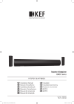
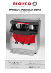
Qwikbrew 2 Service Manual Marco Beverage Systems Ltd. 63d Heather Road, Sandyford Industrial Estate, Dublin 18, Republic of Ireland Ireland Tel: (01) 295 2674 Ireland Fax: (01) 295 3715 UK Tel: (0207) 2744577 UK Tel: (0207) 9788141 Contents Page 1. Introduction 3 2. Safety instructions 4 3. General description 5 4. Installation 8 5. Start Up 9 6. Operation Brewing Coffee Hot water Lock function 9 10 10 11 7. Hygiene 11 8. Technical Data Access to Internal Components PCBs PCB Brewer Display PCB Timer Single 2002 PCB Brew Board 2002 Probes Element De-scaling the tank Pipework and Sprayhead 12 12 12 12 15 16 19 20 20 22 9. Wiring Diagrams 24 10. Amendments 27 11. Spare Parts List 35 Service Manual 1000379 Qwikbrew 2 01-10-12Page 2 of 37 1. INTRODUCTION The information provided in this manual is intended to assist in the installation and maintenance of the Marco Qwikbrew 2 Boiler Brewer. Please read the instructions carefully to prevent accidents and ensure an efficient installation. This manual is not a substitute for any safety instructions or technical data affixed to the machine or its packaging. All information in this manual is current at the time of publication and is subject to change without notice. Only technicians or service providers authorised by Marco should carry out installation and maintenance of these machines. Marco accepts no responsibility for any damage or injury caused by incorrect or unreasonable installation and operation. Service Manual 1000379 Qwikbrew 2 01-10-12Page 3 of 37 2. SAFETY INSTRUCTIONS 1. Read all instructions. 2. To protect against electric shock do not immerse cord and plugs in water or other liquid. 3. Do not let cord hang over edge of table or counter; or touch hot surfaces. 4. Switch off at mains (unplug from outlet) and turn off water supply when not in use and before cleaning. Allow to cool before putting on or taking off parts. 5. Do not operate any appliance with a damaged cord, plugs, or after the appliance malfunctions or has been damaged in any manner. 6. The use of spares and accessories not recommended by Marco may cause damage and/or injuries. 7. Do not use outdoors. Do not place on or near a hot gas or electric burner. 8. Close supervision is necessary when the appliance is used by or near children. 9. Do not use the appliance for anything other than its intended use. 10. Save these instructions. Service Manual 1000379 Qwikbrew 2 01-10-12Page 4 of 37 3. GENERAL DESCRIPTION Qwikbrew 2 – 2.8kW Performance Electrical Coffee output: Half Brew Full Brew Hot Water: Immediate Draw Off Total Recovery at 2.8kW: Connection Fittings Plumbing Pressure Dimensions Height Height incl. Cup Rail Width Depth Depth incl. Drip Tray Service Manual 1000379 Qwikbrew 2 01-10-12Page 5 of 37 Up to 3.4 litres (6 pints) Up to 6.8litres (12 pints) 5.5 litres (10pints) 0.48litres/min (0.85pints/min) 230V 2.8kW c/w 1.5m flex + 13A plug 0.75” BSP Food grade inlet hose supplied 5-50 psi (35-345 kPa) 705mm 775mm 365mm 440mm 575mm Fig.1 - General Arrangement 1 2 3 4 5 6 7 8 9 10 11 12 13 1. 2. Description Cup Rail - 1801510 Label Header Marco - 1900690 Description 9. PCB Brew Display (switches) - 1600324 10. Tap Coffee - 2100295 3. Basket complete - 2300085 11. Tap Hot Water - 2100275 4. Urn Lid - 2300350 12. Curved Panel 5. Plastic Body - 1801480 13. Drip Tray Complete (255mmX186mm)- 2300299 6. Plastic Service Face - 1801490 7. Label Face - 1900700 8. Label Controls - 1900710 Service Manual 1000379 Qwikbrew 2 01-10-12Page 6 of 37 Fig.2 - Internal Arrangement 14 15 16 17 28 18 19 27 20 26 25 21 22 24 23 Description and Part Number 14. Probe Brew Level - 2301310 15. Probe High Level - 2301300 Description and Part Number 22. Pump Nikkiso - 1501540 23. Tee Plastic Overflow - 1801250 16. Probe Low Level - 2301320 24. Inlet Solenoid Valve – 1502190 (1502170 see amendments/part list) 17. Sight Glass - 1700260 25. Element 2.8kW 230V – 1500975 18. Lamp Ballast – 1501211 26. Thermistor Assembly - 1600691 19. Lamp – 1501213 27. PCB Brew Board – 1600321 (1600326 – see amendments/parts list) 20. Lampholder - 1501212 28. PCB Timer – 1600322 (1600323 – see amendments) 21. Drain Valve - 2100100 Service Manual 1000379 Qwikbrew 2 01-10-12Page 7 of 37 4. INSTALLATION Plumbing: 1. Fit a stop valve on a cold water line and attach a ¾” BSP male fitting (e.g. ¾” x ½” 311 or washing machine type stop valve). 2. Connect straight tailpiece of the hose to the stop valve fitting. Make sure that preattached sealing washer is secure. 3. Connect right angled tail piece of the hose to the inlet valve of the boiler (again ¾” BSP). Make sure pre-attached sealing washer is also secure here - see Figure 3. 4. Turn on water supply and check fittings have sealed. 5. A hose is not a permanent connection so it is advisable to close the stop when not in use. Electrical: A moulded 13A plug is factory fitted. A suitable 13A outlet is all that is required. Fig.3 – Plumbing and Electrical Connections Service Manual 1000379 Qwikbrew 2 01-10-12Page 8 of 37 5. START UP Turn the water on at the stop valve and switch the power on at the plug. Press the POWER ON button at the front of the machine. A red light next to the button will illuminate and the machine will start to fill. Note: The machine will not heat until the water has reached the low level probe. When the low-level probe is reached the element is switched on this water is heated to the pre-set temperature (93 – 94.5°C). The machine takes in another small body of water, while continuing to heat. This method of staggered filling (heat-fill cycle) ensures that the temperature in the tank remains within 3 degrees of set temperature. This heat-fill cycle continues until: a) the water level reaches the high level probe and b) the water temperature reaches the pre-set temperature as above. This may take up to 1 hour. Note: When the level of water is at a safe height above the low level, the green READY TO BREW light illuminates. The machine is not full at this level. A brew can be selected, but no hot water is available. Unless a brew is selected, the full quantity of hot water should be available within 25minutes of reaching this level. 6. OPERATION The machine is ready to brew Coffee and 10 pints of Hot Water is available for immediate draw-off when the machine is full and up to temperature. The machine has one large water tank, with an urn recessed into it. When a brew is selected, hot water is pumped from the tank up to the sprayhead and into the filter basket. The coffee runs out of the filter basket into the urn. Since the water tank surrounds the urn, the brewed coffee is kept at temperature. The machine works on a heat fill cycle which means that the temperature in the tank does not drop by more than 3 degrees. The machine will only allow small amounts of cold water into the tank, while continuing to heat to ensure that the temperature does not drop too low. If more hot water is used than the machine can recover (0.48l/min), the amount of water in the tank decreases. If the full quantity of Hot Water is drawn off, the machine will take approximately 25min to recover back up to the high level probe. Note: a brew can still be selected when no Hot Water is available out of the tap. This is due to a buffer of hot water beneath the level of the ‘hot water stand pipe’ inside the tank. This should preferably be a half brew rather than a full brew to ensure shorter recovery times. Drawing off Hot Water while brewing Coffee should not affect the quality of the brew. When the level has dropped to a point where a brew cannot be completed, the ready to brew light goes out and a brew cannot be selected. A 3rd level sensor probe, the ‘Brew Level Probe’ controls this level. After a recovery period (up to 20min), the machine will be ready to brew once again. Note: a longer recovery is required before any substantial amount of Hot Water can be drawn off. Service Manual 1000379 Qwikbrew 2 01-10-12Page 9 of 37 Brewing Coffee: Slide out the coffee filter basket and place a single sheet of filter paper inside Put the correct amount of ground coffee into the filter paper. Your coffee supply company may have pack sizes to suit the brews of your new Qwikbrew 2; if not, as an approximate guide for your first brews: Try about: 110g-130g (4-4½oz) for a 5 pint brew (2.85 litres) 220g-260g (8-9oz) for a 10 pint brew (5.7 litres) Depending on the coffee grind and roast, and on water quality, you may have to adjust these quantities to obtain the optimum flavour. Level off the surface of coffee by gently shaking the filter basket. See Figures 4 and 5. Slide the coffee filter basket into the guide rails in the brew head and push fully home. Select the correct brew on the front panel by pressing either the Half Brew button for a 5 pint brew or the Full Brew button for a 10 pint brew. Press the button until the amber light illuminates. If you make a mistake press the Power switch to turn the machine off. Wait 3 seconds and turn back on again. Select the correct brew. A half brew should take around 4-5min. A full brew should take around 8-10min. These depend on the set up of the machine (factory). As soon as possible after brewing – remove the filter paper with the spent grinds. Note: allow time for all the coffee to drain from the filter basket before removing. A brew can be selected any time the green ‘Ready to brew’ light is illuminated. Fig.4 – Filter Basket Fig.5 – prepared Hot Water: 10 pints of water is available as an immediate draw-off when the machine is full; after this no water is available until the ‘heat fill cycle’ has recovered. This is to ensure that any water drawn off is at the correct temperature. Service Manual 1000379 Qwikbrew 2 01-10-12Page 10 of 37 Lock Function (see figure 6) This is to prevent untrained personnel operating the machine, or accidental misuse by trained personnel. If the lock button is pressed for approx. 5 seconds, a red light next to the button will illuminate. At this point the rest of the control board is locked. The machine will operate as normal, i.e. If it is brewing – it will continue to brew. Once completed another brew cannot be selected, until the lock is disabled. NOTE: The ‘Ready to Brew’ light will still be illuminated, but no brew will be able to be selected. To disable the lock – hold the lock button for 5 seconds once again. This is a particularly useful function in a self-service environment. Fig.6 – Display 7. HYGIENE Like any cooking utensils, the coffee-holding urn of your Qwikbrew 2 must be cleaned properly, regularly. MARCO recommend cleaning after each day's brewing using a proprietary urncleansing compound. MARCO URN CLEANSER is available in 1kg tubs for this purpose. Full instructions are given on each tub. A large Urn cleaning brush and a small sight-glass cleaning brush are supplied to assist in thorough cleaning. Service Manual 1000379 Qwikbrew 2 01-10-12Page 11 of 37 8. TECHNICAL DATA Maintenance should be carried out by Marco approved technicians only. Access to internal components: The Qwikbrew 2 has been designed with ease of service in mind. All the components (PCB’s, inlet solenoid, probes, pump and element) are accessible from the front of the machine. See figure 2 on page 7. Switch off and unplug machine. Remove the two mounting screws positioned in the plastic service panel (near the tap spigots - see Figure 7). Pull the bottom of the plastic service panel away from the curved steel panel. Push the service panel down towards the counter, to release the tongue (top edge), from the plastic body. Gently lift away from the taps (the display board is still connected to the machine! See figure 8) Remove curved steel panel by levering the top edge out first. PCBs: (also see amendments) Figure 9 shows the PCBs and their connections. Three PCBs control the functions of the Qwikbrew 2. 1. Main control board (1600321 - P.C.B. Brew Board 2002) 2. Timer board (1600322 - P.C.B. Timer Single 2002) 3. Display controls (1600324 – P.C.B. Brewer Display Board 2002) P.C.B. Brewer Display Board – 1600324 This PCB consists of four black buttons, five LEDs and three 4-way connectors which connect to the timer board (PCB Timer Single 2002 – 1600322). The board is screwed into brass inserts mounted in the plastic service panel. These screws should be M4 x 6mm s/s. Note: Some early models have M3 mounting screws. When attaching the board to the plastic, ensure that all buttons move freely within the locating holes in the plastic. If they are sticking at all, unscrew slightly and reposition before tightening again. Note that the ribbon cables are unmarked and care should be taken to connect them correctly. Ribbon Connections: 1. Display Top (Between Lock [SW1] /Power [SW2]) Timer Board J1 2. Display Middle (between Power [SW2]/Half brew [SW3]) Timer Board J2 3. Display Bottom (between Half brew [SW3]/Full brew [SW4]) Timer Board J3 (See Figure 10) Service Manual 1000379 Qwikbrew 2 01-10-12Page 12 of 37 Fig.7 – Plastic Service Panel Plastic Service Panel Mounting Screws Fig.8 – Plastic Service Panel Removed Service Manual 1000379 Qwikbrew 2 01-10-12Page 13 of 37 Fig.9 – PCB connections Fig.10 – Display PCB connections Service Manual 1000379 Qwikbrew 2 01-10-12Page 14 of 37 P.C.B. Timer Single 2002 – 1600322 Figure 11 shows a close up of the timer board. This timer developed in 2002 is a simple timer/pump driver, which uses information supplied by the Brew Board (1600321) to control brewing function. Ribbon Connection: 1. Timer Board J6 Brew Board DATA I/O The switching is done using a line driver (triac based - zero voltage switching). This component operates off the neutral from the pump. Note: The pump has a live wire connected permanently. The switching is done on the return/neutral side. Adjusting Brew Times: The pot on the timer board adjusts the half brew time. The full brew time is always double the half brew time. The half brew range is currently set at approx: 3 minutes to 6 minutes. Adjusting clockwise – increases half brew time. Adjusting anti-clockwise – decreases half brew time. Note: the first batch of machines (serial no. 08022211 – 08022230) requires that the timer board be reset for changes to take effect. Once the pot has been turned, the machine needs to be switched off and switched on again for the new settings to be saved. The brew times will not change until the machine has been reset. Machines with serial numbers outside of this range DO NOT need to be reset. The change will automatically be detected before a brew commences. Connector J5 (not used) Fig.11 – Timer PCB Connector J6 To PCB Brew Board Data I/O Time Adjust Pot Neutra from PCB Brew Board Connector J1 To Display PCB top Connector J2 To Display PCB middle Connector J3 To Display PCB bottom Microchip Software:SM5023-.. matches Brew PCB code SM5022-.. From Pump Neutral (black/white) P.C.B. Brew Board 2002 – 1600321 (NOTE: also see amendments) Service Manual 1000379 Qwikbrew 2 01-10-12Page 15 of 37 This is a modification to the EZT boiler PCB. The software code on this PCB (SM1078-05 or SM5022-..) enables it to be used in this brewer or any other standard Marco Boiler – EZT 400/700, Comet2, Aquarius 15, 3/30,6/30,6/45. The jumper J12 (6below) selects either boiler or brewer mode. Fig.12 – PCB Brew Board 2002 1 2 3 4 5 24 23 6 22 7 21 8 20 19 9 18 10 17 16 11 15 14 13 12 Service Manual 1000379 Qwikbrew 2 01-10-12Page 16 of 37 Components of PCB Brew Board 2002 (fig. 12): 1. 2. Transformer Power On/Off – 2way connector o looped on this machine LEDs - 5way connector o not used on this machine Data I/O – 4way o connects to timer PCB J6 Earth Tab Mode of Operation Jumper to be positioned closest to the transformer for Boiler mode to be positioned furthest away from transformer for Brewer mode Water Level – 5way connector connects to Low level, High level and Brew level probes. 3. 4. 5. 6. 7. 8. Microchip – version number The software code on this microchip is very important. Part no, 1600321 should have the software code SM5022-.. The Timer PCB should have software code SM5023-.. These two PCBs are matched. Subsequent modifications have been made to the PCBs and care should be taken that the Timer and Brewer PCB are matched together. (See amendments) 9. 10. 11. 12. 13. 14. Temperature Adjust Pot o to increase temp – adjust clockwise o to decrease temp – adjust anti-clockwise Temperature Range Jumper o controls three temperature ranges o should be on the middle pins for boiler/brewer operation Thermistor Connector Daughter PCB Connector o used in 5.6kW machines Relay - Heater Safety o backup relay for element Relay – Heater o switches the element 15. Triac controls the switching of relays at zero voltage. this lengthens the life of relays, by removing the arc (flash) during switching which wears the contacts on the relay. 16. 17. 18. 19. 20. 21. 22. 23. 24. Heater/Element Tab Live Tab Inlet Solenoid Tab Live tab - spare Suppressor Relay – Inlet Solenoid o switches the inlet solenoid Fuse Neutral tab Neutral tab – spare Service Manual 1000379 Qwikbrew 2 01-10-12Page 17 of 37 General Operation - PCB Brew Board 2002 (software vers. SM5022-..) -1600321 When the machine is switched on, the PCB checks what state the machine is in, by checking probe levels and temperature. If the low level probe is uncovered, the machine will take in mains water until this probe is in contact with the water. At this level, the element is switched on and this body of water is heated to the preset temperature (temp adjust pot), approx 93.5-96C. More mains water is taken in (heating does not stop) until the temperature sensor senses a drop of 1-2 degrees. The machine stops taking in water and allows time for this water to reach preset temperature. This is the Heat-Fill cycle. This cycle will continue until the high level probe is reached. If the water level drops off the high level probe, this cycle is repeated. By using this method, the water in the tank remains between favourable temperature limits. However, this does mean that the machine can run out of hot water. Note: old versions of the Qwikbrew did not work on the heat fill system, and the level of the water remained at the high level probe regardless of temperature. In between the low level and high level is a 3rd level probe – ‘the brew level probe’. There is 12-13 pints of water between this level and the low level. A brew of coffee can be started at any point above this level. A normal full brew is approx. 11 pints of water – so this is a safe level, even in a situation of mains pressure drop. In normal circumstances approx. 6 pints of water is taken in and recovered during a full brew. Therefore, there should always be at least 7 pints of water above the low level cut off. Approximately 15mm (2 pints) above the Brew level probe is the Hot Water Draw off limit. This is the level in the tank at which the Hot Water tap runs out of water. A brew can still be selected at this point. Drawing off water at any time should not affect the brewing system. Service Manual 1000379 Qwikbrew 2 01-10-12Page 18 of 37 Probes: As mentioned earlier, there are 3 probes (low level, high level and brew level) on the Qwikbrew 2, the positions of which are shown in figure 2. Figures 13 and 14 show how the probes are removed. Note: Tank does not have to be drained to remove any probes. The probes and bracket are sealed against the wall of the tank with 2 M6 nuts that screw onto studs welded to the tank. Remove these nuts and pull the probe assembly out. Fig.13- remove nuts Fig.14 – remove probe Low Level Probe assembly - 2301320 (see figure 15) The low level probe is mounted on the sight glass side of the machine, and is connected to the Brew Board PCB with a yellow wire. High Level Probe assembly - 2301300 (see figure 15) The high level probe is mounted in the top centre of the tank, and is connected to the Brew Board PCB with an orange wire. Brew Level Probe assembly - 2301310 (see figure 15) The brew level probe is mounted on the tank near to timer PCB, and is connected to the Brew Board PCB with a red wire. Fig.15- probe assemblies Low Level Probe Assembly 2301320 High Level Probe Assembly 2301300 Brew Level Probe Assembly 2301310 Service Manual 1000379 Qwikbrew 2 01-10-12Page 19 of 37 Element: Figures 16 and 17 show the two types of element used on the Qwikbrew 2. The element shown in figure 16 is used on the first batches of the machine. This is either a 2.8kW 220V or a 2.8kW 240V depending on whether the machine is in Ireland or the UK. Since the European standard voltage is 230V, we are in the process of changing our elements to suit this. Figure 17 shows the element to be used on new batches of the Qwikbrew 2. This shape of element has a great advantage. Fig.16 Fig.17 Replacing the Element: Switch off the machine and remove the plug from the socket. Drain the tank using the drain valve at the front of the machine (see figure 18). Unscrew the 8 M6 nuts that clamp the clean out door against the tank wall. Pull clean out door back and check element. If element is of the type in fig. 16, remove element nuts on the front of the clean out door. Remove clean out door. (If element is of type in figure 17, pull the assembly straight out of the tank.) Not the position of the red silicone o-ring - remove and discard. Remove element by sliding one leg out at a time (see figures 21 and 22). Replace in reverse order. Use a new red silicone O-ring (1800770). Do not over-tighten M6 nuts. Check that the clean out door is sealed at temperature before leaving site. Service Manual 1000379 Qwikbrew 2 01-10-12Page 20 of 37 De-scaling the tank: Follow instructions for removing the element. The tank can now be cleaned through the clean out door (see figure 23). Fig.18 Fig.20 Fig.22 Service Manual 1000379 Qwikbrew 2 01-10-12Page 21 of 37 Fig.19 Fig.21 Fig.23 Pipework and Sprayhead: Figure 24 highlights the hoses and connections at the front of the machine. Figure 25 details hose connections beneath the tank. Figure 26 highlights the hoses and connections at the back of the machine. Fig.24 Urn Overflow - to Drip tray Tank Overflow - to Drip tray Pump Inlet Plastic T-piece - 1801250 Fig.25 Inlet Solenoid to Tank (see amendments) Pump Outlet to Sprayhead Fig.26 Hose Clip Restrictor – 1800545 (obsolete - see amendments) Sprayhead (obsolete - see amendments) T-piece plastic – 1801255 (obsolete - see amendments) Pump Outlet to Sprayhead (obsolete - see amendments) Service Manual 1000379 Qwikbrew 2 01-10-12Page 22 of 37 The Sprayhead: (see amendments) To access the sprayhead, simply pull out the cup rail and lift off the lid (see figures 27, 28 and 29). Fig.27 Fig.28 Fig.29(see amendments) The pump feed to the sprayhead is shown in figure 26. A length of silicone hose (12mmID) connects the pump to a T-piece (either stainless steel or high temp plastic – plastic to be standard on future machines). A short length of hose connects the T-piece to a stainless steel tube welded to the tank. Another piece of hose connects the T-piece to the sprayhead. There are currently two types of sprayhead on the Qwikbrew 2: The adjustable sprayhead is shown in figure 30. (obsolete – see amendments) This has a ball valve attached to the sprayhead - opening or closing the valve can adjust the flow. These sprayheads will not be used on future models. The standard sprayhead is shown in figure 31. (obsolete – see amendments) This sprayhead has a tail-piece connection with an 8mmID silicone tubing sleeve attached to it. This acts like a reducer, so that the 12mmID hose can connect to the tailpiece. Small pieces of this 8mmID silicone hose might be positioned inside the larger hose at the inlet and outlets of the T-piece. These act as restrictors and help control the flow rate. The other control restrictor is a black hose clip type E (1800545). This fits around the silicone hose feeding to the sprayhead. The flow can be adjusted by closing the hose clip. There are no restrictors of the type found on previous Marco brewers. The flow rate is controlled by pipe work and in some cases hose clips. The larger bores in the hoses should prevent failures due to scale blockages. Fig.30 (obsolete) Service Manual 1000379 Qwikbrew 2 01-10-12Page 23 of 37 Fig.31 9. WIRING DIAGRAMS (also see amendments): Wiring diagram for 2.8kW machines with serial numbers up to 04031237 Service Manual 1000379 Qwikbrew 2 01-10-12Page 24 of 37 Wiring diagram for 2.8kW machines with serial numbers from 10040001 Service Manual 1000379 Qwikbrew 2 01-10-12Page 25 of 37 Wiring diagram for 5.6kW machines Service Manual 1000379 Qwikbrew 2 01-10-12Page 26 of 37 AMENDMENTS NOTE: The first four digits of the serial number denote the month and year of manufacture. The remaining four digits represent a factory assigned sequential serial number. This is important for identifying machine versions. See example below. 04 03 2906 MONTH YEAR FACTORY NUMBER Machines with serial numbers 04031237 to 10040001: These machines have the following modifications: 1. The inlet solenoid valve is the right-angled type - Part no. 1502170. This replaces Part no. 1502190.The inlet hose from the inlet connects to an elbow welded to the bottom of the tank. 2. The sprayhead design is the flow through type. The sprayhead has two pipes attached to it. The small pipe comes directly from the pump. The large silicone tube is the bypass and feeds back into the hot water tank. See the picture below. Sprayhead Complete – part no. 1401550 Service Manual 1000379 Qwikbrew 2 01-10-12Page 27 of 37 AMENDMENTS (cont): Machines with serial numbers 10040001 - present: These machines have the following modifications: 1. The PCB Brew Board 2004 (software: SM5029-..) - Part No. 1600326 replaces the PCB Brew Board 2002 (software: SM5022-..) – Part No. 1600321. This PCB is essentially the same, but with new software on the microchip. The PCB Timer Dual 2004 (software: SM5023-..) – Part No. 1600323 replaces the PCB Timer Single 2002 (software: SM5023-..) – Part No. 1600322. These PCBs allow the brewer to be operated in heat-fill mode or continuous fill mode. The software has been modified so that the error diagnostic signals can be displayed by flashing the red Power On/Off LED. The following section details the PCB change. Qwikbrew2 PCB modification: Electronics modification: Timer and Brew Board Replacement Marco are currently phasing out the PCB brew board 2002 (Part No. 1600321) and the PCB Single Timer (Part No. 1600322). These are found on all Qwikbrew 2 machines produced to date. Future batches of Qwikbrew 2 machines will use the PCB Brew Board 2004 (Part No. 1600326) and the PCB Dual Timer (Part No. 1600323) as standard. Note that the TIMER-MAIN PCB (Brew Board) combination is critical. The software codes are linked between the Timer and the Brew board PCB. Therefore, if a timer PCB is replaced with the new version, the Main PCB (or microchip) should be replaced too. The machine will not operate unless the Timer and Main PCB combination is correct. Each PCB has a label on the microchip, which has the software code version printed on it. These software codes and corresponding part no’s are detailed below: Obsolete PCB combination (being phased out): 1600321 – PCB Brew Board 2002 – (software code SM5022-..) 1600322 – PCB Timer Single – (software code SM5023-..) New PCB combination: 1600326 – PCB Brew Board 2004 – (software code SM5029-..) 1600323 – PCB Timer Dual – (software code SM5030-..) The procedure for changing the Timer PCBs is detailed on the following pages. Service Manual 1000379 Qwikbrew 2 01-10-12Page 28 of 37 AMENDMENTS: Machines with serial numbers 10040001 - present: Modification of Qwikbrew 2 – replacing the Single Timer with the Dual Timer: 1. Press the power button to switch the machine off. 2. Unplug the machine. 3. Disconnect the Display PCB (1600324) ribbon cable links from the Single Timer PCB (1600322). Disconnect the Brewer PCB (1600321) ribbon cable link from the Single Timer PCB (1600322). Disconnect the spade terminals from the Single Timer PCB (1600322). See Fig.1 below. 4. Remove Single Timer PCB (1600322). 1600322 1600321 1600324 Fig.1 Service Manual 1000379 Qwikbrew 2 01-10-12Page 29 of 37 AMENDMENTS: Machines with serial numbers 10040001 – present Qwikbrew2 PCB modification (cont): 5. Fit the new Dual Timer PCB (1600323) into position. This can only be fitted one way. The mains connectors will be at the top. Ensure that the PCB is pressed firmly on to the pillar supports (this is necessary to keep a good clearance between the mains terminals and PCB bracket). See Fig.2 below. 1600324 1600323 1600326 Fig.2 6. 7. 8. 9. Reconnect the Display PCB (1600324) as follows: The top ribbon cable to J1 on the Dual Timer PCB (1600323). The middle ribbon cable to J2 on the Dual Timer PCB (1600323). The bottom ribbon cable to J3 on the Dual Timer PCB (1600323). See Fig.2 and Fig.3. Reconnect the ribbon cable from the Brewer PCB (1600321) Data I/O to J6 on the Dual Timer PCB (1600321). See Fig.2 and Fig.3. Reconnect the spade terminals as shown in Fig.2 and Fig.3. The selector switches should be in the positions shown in the inset in Fig.3. VR1 SELECTOR SWITCHES J6 J1 J2 J3 Fig.3 Service Manual 1000379 Qwikbrew 2 01-10-12Page 30 of 37 AMENDMENTS: Machines with serial numbers 10040001 – present Qwikbrew2 PCB modification (cont): NOTE: Whenever the Dual Timer 1600323 replaces the single timer 1600322, a new main Brewer PCB 1600326 is required. The existing PCB 1600321 on the unit can be converted to the new PCB 1600326 by replacing the main microchip on the PCB. If a microchip has been supplied, carefully remove the microchip from the Brewer PCB (1600321) and replace with the new chip. Ensure that the chip is inserted the correct way – the semi circle groove should be at the bottom. NOTE: THESE COMPONENTS ARE FRAGILE AND SHOULD BE HANDLED WITH CARE. This new chip contains the software to drive the Dual Timer PCB and contains code that allows the machine to be used in Heat-Fill mode or Continuous Fill mode. The position of the Jumper J12 above the microchip determines the mode of operation. For Heat fill mode, the jumper should be positioned nearest the transformer. For Continuous Fill mode, the jumper should be positioned furthest away from the transformer. Fig.4 shows the jumper in Continuous Fill mode. J12 Fig.4 The software version on the Brewer PCB microchip should be version SM5029-01 or above (SM5029-02 or SM5029-03 etc). Note that the temperature may need to be reset on the machine. The Half brew time can be adjusted through VR1 on the Dual Timer PCB (1600323). Increase the Half brew time by turning VR1 clockwise. To decrease the brew time – anticlockwise. The Full brew time is double the Half brew time. Service Manual 1000379 Qwikbrew 2 01-10-12Page 31 of 37 AMENDMENTS: Machines with serial numbers 10040001 – present Diagnostic indication Any Qwikbrew 2 machine fitted with the PCB Brew Board 2004–Part No. 1600326 (software code: SM5029-..) and PCB Dual Timer-Part No. 1600323 (software code: SM5030-..), will display error signals via flashes of the Power LED. This LED will flash when an error is detected. The number of flashes in a cycle references a particular problem. This is detailed in the diagnostic guide. TROUBLESHOOTING – DIAGNOSTIC GUIDE: If an error is detected a sequence of flashes is displayed through the POWER LED. The length of time and recovery method of each of these flashing displays is detailed below: 2 Flash Cycle – below low level Display pattern: 2 quick flashes then a short pause - repeated. Electronic check and action: This indicates that the low level circuit is open i.e. the probe is not in contact with the water. The element is switched OFF at this stage and the inlet is left ON. (note that if this is a low probe wiring fault, the water will stop at the high level probe regardless of the status of the low level). This is a recoverable error i.e. the machine does not need to be reset when the problem is solved. (e.g. if a closed mains water stop valve is the problem, opening the valve will allow water into the machine and normal function will resume when the low level probe is reached) Probable causes: 1. The water level is below the low level probe, which is normal when the machine fills for the first time. (Can be flashing for up to 5 min at start up) 2. The low level probe wire is disconnected, or there is another wiring fault (eg. a bad earth (return) connection between the PCB and the Tank) Action required: 1. Check that the water pressure is OK and ensure that the stop valve is open. 2. Check that the inlet solenoid is working. 3. If the water level is above the level of the low probe, check the probe circuit wiring Service Manual 1000379 Qwikbrew 2 01-10-12Page 32 of 37 AMENDMENTS: Machines with serial numbers 10040001 present TROUBLESHOOTING – DIAGNOSTIC GUIDE cont: 3 Flash Cycle – thermistor open circuit Display pattern: 3 quick flashes then a long delay (up to 15 seconds) - repeated. Electronic check: This indicates that the Thermistor is measuring such a large resistance that it assumes the thermistor circuit is open. The element and inlet valve are turned OFF when this error is detected This is a recoverable error. When the correct range of resistance is measured, normal operation resumes Probable causes: 1. The thermistor probe is unplugged from the 4way connector on the PCB or the thermistor has failed open circuit. Action required: 1. Check that the thermistor is plugged in to the PCB correctly. If it is, replace the thermistor. 4 Flash Cycle (Heat Fill Mode Only) – NOT HEATING Display pattern: 4 quick flashes then a short pause - repeated. Electronic check: This checks that the temperature is increasing when the heater is on. Measures the rate that the temperature increases in a specified time. This error is only displayed after 20 mins of the heater being on continuously. When the error is detected, the element and inlet valve are turned off. This is a non recoverable error. The machine needs to be reset when this problem is solved. Probable causes: 1. All the elements have failed 2. Wiring fault Action required: 1. Check that the resistance on the elements. If there is a reasonable resistance (1525Ω)on the element it probably has not failed, so the wiring might be at fault. NOTE: for this error to be displayed all elements would have to fail. 5 Flash Cycle – THERMISTOR SHORT CIRCUIT Display pattern: 5 quick flashes then a short pause - repeated. Electronic check: This indicates that the Thermistor is measuring zero resistance. It assumes the thermistor has failed sort circuit. The element and inlet valve are turned OFF when this error is detected This is a recoverable error. When the correct range of resistance is measured, normal operation resumes. Probable causes: 1. The thermistor has failed. Action required: 1. Replace the thermistor. Service Manual 1000379 Qwikbrew 2 01-10-12Page 33 of 37 AMENDMENTS: Machines with serial numbers 10040001 – present TROUBLESHOOTING – DIAGNOSTIC GUIDE cont: 6 Flash Cycle (heat Fill Mode Only) – NOT FILLING Display pattern: 6 quick flashes then a short pause - repeated for approx 2min. Then normal function resumes for 1min30secs – then flashes for 2min again – this cycle is repeated. Electronic check: This checks that the inlet solenoid valve is not kept ON for more than 1min30secs when in the heat fill cycle. Note: this error is only checked once the water level has reached the low level probe and the machine has begun the heat fill cycle. This is a recoverable error. In the heat fill cycle, even with reasonably low water pressure the inlet solenoid valve usually only stays ON for approx 5-6 seconds. If the inlet valve stay ON for more than 1min30secs, there is a problem with the inlet valve or the mains water supply. After 1min30seconds the 6 flash cycle is displayed for 2min – the inlet solenoid valve is turned OFF during this time. After this 2min cycle, normal operation resumes i.e. the machine attempts to fill by opening the inlet solenoid valve once more. If after 1min30secs no water has come into the machine, the 6flash sequence is displayed again. This cycle is repeated. Probable causes: 1. Mains water pressure problem or the mains water stop valve is closed. 2. Inlet solenoid valve failure. Action required: 1. Check the mains water supply. If it is good, wait 5 minutes to check that the error cycle is continuing. 2. If the mains water supply is good, check that the inlet solenoid valve is working. Service Manual 1000379 Qwikbrew 2 01-10-12Page 34 of 37 11. PART LISTS Machines with serial numbers before 04031237 PART NO. 1801510 1900690 1900700 1900695 1900710 1801480 1801490 1801436 2300085 2300350 2100295 2100275 1401170 1400550 1600324 1600322 1600321 1600691 2301320 2301310 2301300 1700260 1501213 1501212 1501211 2100100 1400990 1402370 1501540 1801250 1801255 1800545 1800540 1800555 1502190 1500975 1800770 1801195 1801200 1800190 1401800 8000150 1800690 8000240 1700010 1700000 DESCRIPTION CUP RAIL LABEL HEADER MARCO LABEL FACE LABEL BLANK CLEAR (SIGHTGLASS) LABEL DISPLAY/CONTROLS PLASTIC BODY PLASTIC SERVICE FACE PLASTIC DRIP TRAY COMPLETE (BLACK) BASKET COMPLETE URN LID TAP 'COFFEE' COMPLETE TAP 'HOT WATER' COMPLETE 3/4" BSP CHROME NUT FOR TAP CIRCLIP FOR TAP PCB DISPLAY QB2 PCB TIMER SINGLE 2002 (SM5023-..) PCB BREW BOARD 2002 (SM5022-..) THERMISTOR ASSEMBLY PROBE LOW LEVEL QB2 SINGLE PROBE BREW LEVEL QB2 SINGLE PROBE HIGH LEVEL QB2 SIGHTGLASS LAMP LAMPHOLDER LAMP BALLAST DRAIN VALVE LOCKNUT 1/2" BSP BRASS (DRAIN VALVE) COPPER WASHER (FOR DRAIN VALVE) PUMP NIKKISO TEE PIECE PLASTIC OVERFLOW TEE PIECE PLASTIC (TO SPRAYHEAD) HOSE CLIP TYPE E (SMALL - FOR RESTRICTOR) HOSE CLIP TYPE F (FOR T-PIECES, SPRAYHEAD ETC.) HOSE CLIP TYPE M (LARGE - FOR PUMP INLET) VALVE INLET SOLENOID ELEMENT 2.8KW 230V (IF AVAILABLE) O-RING 4" RED SILICONE (FOR CLEANOUT DOOR) SPRAYHEAD COMPLETE STRAIN RELIEF BUSH (FOR ELECTRICAL CORD) FEET NYLON SCREW PLASTITE FOR FEET FILTER PAPER WATER INLET HOSE URN CLEANSER URN BRUSH SIGHTGLASS BRUSH Service Manual 1000379 Qwikbrew 2 01-10-12Page 35 of 37 Machines with serial numbers 04031237-10040001 PART NO. 1801510 1900690 1900700 1900695 1900710 1801480 1801490 2300299 2300085 2300350 2100295 2100275 1401170 1400550 1600324 1600322 1600321 1600691 2301320 2301310 2301300 1700260 1501213 1501212 1501211 2100100 1400990 1402370 1501540 1801250 1800540 1800555 1502170 1500975 1800770 1402550 1801200 1800190 1401800 8000150 1800690 8000240 1700010 1700000 DESCRIPTION CUP RAIL LABEL HEADER MARCO LABEL FACE LABEL BLANK CLEAR (SIGHTGLASS) LABEL DISPLAY/CONTROLS PLASTIC BODY PLASTIC SERVICE FACE DRIP TRAY COMPLETE (255mmX186mm) BASKET COMPLETE URN LID TAP 'COFFEE' COMPLETE TAP 'HOT WATER' COMPLETE 3/4" BSP CHROME NUT FOR TAP CIRCLIP FOR TAP PCB DISPLAY QB2/MB2 PCB TIMER SINGLE 2002 (SM5023-..) PCB BREW BOARD 2002 (SM5022-..) THERMISTOR ASSEMBLY PROBE LOW LEVEL QB2 SINGLE PROBE BREW LEVEL QB2 SINGLE PROBE HIGH LEVEL QB2 SIGHTGLASS LAMP LAMPHOLDER LAMP BALLAST DRAIN VALVE LOCKNUT 1/2" BSP BRASS (DRAIN VALVE) COPPER WASHER (FOR DRAIN VALVE) PUMP NIKKISO TEE PIECE PLASTIC OVERFLOW HOSE CLIP TYPE F (FOR T-PIECES, SPRAYHEAD ETC.) HOSE CLIP TYPE M (LARGE - FOR PUMP INLET) VALVE INLET SOLENOID - 90deg ELEMENT 2.8KW 230V M-SHAPE O-RING 4" RED SILICONE (FOR CLEANOUT DOOR) SPRAYHEAD COMPLETE STRAIN RELIEF BUSH (FOR ELECTRICAL CORD) FEET NYLON SCREW PLASTITE FOR FEET FILTER PAPER WATER INLET HOSE URN CLEANSER URN BRUSH SIGHTGLASS BRUSH Service Manual 1000379 Qwikbrew 2 01-10-12Page 36 of 37 Machines with serial numbers 10040001- present PART NO. 1801510 1900690 1900700 1900695 1900710 1801480 1801490 1801436 2300085 2300350 2100295 2100275 1401170 1400550 1600324 1600323 1600326 1600691 2301320 2301310 2301300 1501191 1700260 1501213 1501212 1501211 2100100 1400990 1402370 1501540 1801250 1800540 1800555 1502170 1500975 1800770 1402550 1801200 1800190 1401800 8000150 1800690 8000240 1700010 1700000 DESCRIPTION CUP RAIL LABEL HEADER MARCO LABEL FACE LABEL BLANK CLEAR (SIGHTGLASS) LABEL DISPLAY/CONTROLS PLASTIC BODY PLASTIC SERVICE FACE PLASTIC DRIP TRAY COMPLETE (BLACK) BASKET COMPLETE URN LID TAP 'COFFEE' COMPLETE TAP 'HOT WATER' COMPLETE 3/4" BSP CHROME NUT FOR TAP CIRCLIP FOR TAP PCB DISPLAY QB2/MB2 PCB TIMER DUAL 2004 (SM5030-..) PCB BREW BOARD 2004 (SM5029-..) THERMISTOR ASSEMBLY PROBE LOW LEVEL QB2 SINGLE PROBE BREW LEVEL QB2 SINGLE PROBE HIGH LEVEL QB2 HARNESS PROBE QB2 SINGLE & TWIN SIGHTGLASS LAMP LAMPHOLDER LAMP BALLAST DRAIN VALVE LOCKNUT 1/2" BSP BRASS (DRAIN VALVE) COPPER WASHER (FOR DRAIN VALVE) PUMP NIKKISO TEE PIECE PLASTIC OVERFLOW HOSE CLIP TYPE F (FOR T-PIECES, SPRAYHEAD ETC.) HOSE CLIP TYPE M (LARGE - FOR PUMP INLET) VALVE INLET SOLENOID - 90deg ELEMENT 2.8KW 230V M-SHAPE O-RING 4" RED SILICONE (FOR CLEANOUT DOOR) SPRAYHEAD COMPLETE STRAIN RELIEF BUSH (FOR ELECTRICAL CORD) FEET NYLON SCREW PLASTITE FOR FEET FILTER PAPER WATER INLET HOSE URN CLEANSER URN BRUSH SIGHTGLASS BRUSH Service Manual 1000379 Qwikbrew 2 01-10-12Page 37 of 37