1
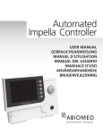
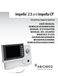
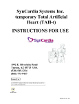
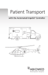
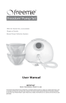
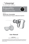
BVS 5000t Operator’s Manual
ABIOMED® BVS® 5000t
BI-VENTRICULAR SUPPORT SYSTEM
TRANSPORT/ BACKUP CONSOLE
Operator's Manual
CAUTION
Federal (U.S.A.) law restricts this device to sale, distribution
and use by or on the order of a physician.
For use only by personnel trained in accordance with the
ABIOMED Training Program.
Read all warnings, precautions, and instructions carefully prior to use.
Manufactured by:
ABIOMED, Inc.
22 Cherry Hill Drive
Danvers, MA 01923 USA
N. America: 1-800-422-8666
(24-Hour, Emergency Hotline)
or (978) 777-5410
BVS 5000t Transport / Backup Console:
UL 2601-1 Classifications
Class 1 Equipment
Type B Applied Part
IPX1 Protection
Continuous Operation
0050-9000 Rev. C
September 2002
ABIOMED, Inc.
page 1
BVS 5000t Operator’s Manual
ABIOMED, Inc. and our authorized representatives and distributors are responsible
for the effect of safety, reliability, and performance of the equipment only if:
All service, repairs, and periodic maintenance are carried out by
ABIOMED, Inc. or its authorized representative or distributor.
The BVS 5000t is only used in accordance with the Instructions for Use.
Only use the BVS 5000t console with the BVS Blood Pumps, BVS Cannulae, and BVS Accessories.
Copyright 2000, 2001, 2002
by ABIOMED, Inc.
All rights reserved.
“ABIOMED, BVS, Angioflex, and the AB logo are registered trademarks of ABIOMED, Inc. in the United
States, and trademarks of ABIOMED, Inc. in the other countries. Additional trademarks registrations are
being applied for in the U.S. and other countries”
Tyvek and Mylar are trademarks of E.I. Dupont de Nemours and Co. Inc.
Hemashield is a trademark of Meadox Medicals, Inc.
ABIOMED, Inc.
page 2
BVS 5000t Operator’s Manual
TABLE OF CONTENTS
Section 1 Introduction
1.1
1.2
1.3
1.4
1.5
System Overview ......................................................................................................................
BVS Blood Pump ......................................................................................................................
BVS Cannulae...........................................................................................................................
BVS Console.............................................................................................................................
Accessories...............................................................................................................................
5
5
5
6
6
Section 2 Indications For Use............................................................................................ 9
Section 3 Contraindications For Use.................................................................…...........10
Section 4 Specifications
4.1
4.2
Console..................................................................................................................................... 11
BVS Blood Pump Specifications ............................................................................................... 13
Section 5 Installation and Operation
5.1
5.2
5.3
5.4
5.5
5.6
5.7
Installation…………................................................................................................................... 15
Console Power Up and Self-Test............................................................................................... 15
BVS Blood Pump Preparation.................................................................................................... 16
Recommended Cannulation Method.......................................................................................... 16
Interconnection Procedure.......................................................................................................... 16
Pumping...................................................................................................................................... 16
Battery Operation and Transport................................................................................................ 17
Section 6 Alarms and Status Indicators
6.1
6.2
6.3
6.4
6.5
6.6
Introduction................................................................................................................................ 20
Pressure and Vacuum Alarms.................................................................................................... 20
Alarm Mute..................................................................................................................................21
Alarm Volume............................................................................................................................. 21
Battery Status............................................................................................................................. 21
Surge Protection Status.........................…................................................................................. 22
Section 7 Console Failure
7.1
7.2
7.3
Foot Pump.................................................................................................................................. 23
Removing and Operating the Foot Pump................................................................................... 23
Stowing Foot Pump.................................................................................................................... 23
Section 8 Routine Maintenance and Shipment
8.1
Routine Check of Backup Systems............................................................................................ 25
8.2
Foot Pump Test.......................................................................................................................... 25
8.3
Self-Test Routine....................................................................................................................... 25
8.4
Separating Upper and Lower Modules...................................................................................... 25
8.5
Packaging for Shipment............................................................................................................. 25
8.6
Cleaning..................................................................................................................................... 25
8.7
Scheduled Maintenance............................................................................................................ 26
8.8
BVS Replacement Parts............................................................................................................ 26
8.9
Service....................................................................................................................................... 26
8.10 Ordering Information.................................................................................................................. 27
Operating Instruction Placard............................................................................................................ 29
Symbol Definitions.............................................................................................................................. 33
Patient Transport with the BVS 5000® Bi-Ventricular Support System....................................... 35
ABIOMED, Inc.
page 3
BVS 5000t Operator’s Manual
THIS PAGE LEFT BLANK INTENTIONALLY
ABIOMED, Inc.
page 4
BVS 5000t Operator’s Manual
SECTION 1: INTRODUCTION
1.1
System Overview
The ABIOMED BVS 5000 Bi-Ventricular Support System is an automated bi-ventricular support
device intended to provide short term support of the left and/or right sides of the heart. The
system drive console, the BVS 5000t Transport/Backup Console, supplies pneumatic power to
a disposable blood pump. The beat rate and systolic/diastolic intervals are fixed.
The ABIOMED BVS 5000t is indicated for use as a backup console for either an ABIOMED
BVS 5000 Bi-Ventricular Support System or an ABIOMED BVS 5000i Bi-Ventricular Support
System. It can also be used to facilitate patient transport. The device requires constant
monitoring by a trained operator.
1.2
BVS Blood Pump (Refer to Instructions For Use)
The disposable BVS blood pump (Figure 1.1) is a pneumatically driven two-chambered device,
which supports one side of the heart. The pump is placed external to the patient. Blood inflow
from the left atrium is returned to the thoracic aorta. Inflow from the right atrium returns to the
pulmonary artery. Connection of the blood pump to the patient uses transthoracic cannulation
techniques.
Figure 1.1 BVS Blood Pump
1.3
BVS Cannulae (Refer to Instructions for Use)
There are two cannulae supplied with each blood pump; one for left and right atrial
connections, and one for the aortic or PA connection. The atrial and arterial cannulae are both
supplied with tie wraps, a tunneling bullet for tunneling the cannula through the skin, and a
cannula restraint for the cannula connector junction. The arterial cannula is manufactured with
a coated woven graft bonded to one end. This graft permits end-to-side anastomosis of the
cannula to the PA or aorta. The coating on the graft eliminates the need for preclotting and
provides a graft porosity <1cc/min/cm2.
ABIOMED, Inc.
page 5
BVS 5000t Operator’s Manual
1.4
BVS 5000 Transport / Backup Console
The BVS 5000t Console (Figure 1.2) is a logic device-controlled pneumatic drive system which
can operate one or two disposable blood pumps. The console operates at a fixed beat rate and
systolic/diastolic ratios. Beat rate is displayed on the control panel.
The console incorporates several systems to ensure safe operation. Automatic self-testing
upon power up alerts the operator about potential problems while the operator observes the
control panel during the test procedure. Battery backup is provided for one hour (when fully
charged) of portable or power fail operation. Alarms alert the operator to abnormal flow or
pressure conditions.
The console also has a level of operational redundancy. Should the console fail, a footoperated pump allows continued support. It also has a failsafe battery back up system to
provide a minimum of one hour of operation should AC Mains power fail.
Figure 1.2 BVS System 5000t Transport/ Backup Console
1.5
Accessories
Pole Mount: (Refer to Instructions For Use - Section 5.7.1)
The BVS I.V. Pole Mount is provided as a mounting bracket for the BVS Blood Pump while in
use. It attaches to an I.V. pole and can accommodate two blood pumps.
Bed Mount: (Refer to Instructions For Use - Section 5.7.1)
The BVS Bed Mount is also an accessory that can be used to secure the blood pump during
patient transport. It slides between the mattress and bed and can accommodate two pumps.
This obviates the need for transporting the pumps on an I.V. pole next to the patient.
ABIOMED, Inc.
page 6
BVS 5000t Operator’s Manual
BVS Blood Pump Sling: ( See instructions for Use later in patient transport section)
This accessory is only used with the BVS 5000t. It allows for horizontal positioning of the blood
pump attached to the stretcher or bed.
Pump Mount Set:
Includes Pole and Bed Mounts, as described above.
ABIOMED, Inc.
page 7
BVS 5000t Operator’s Manual
THIS PAGE LEFT BLANK INTENTIONALLY
ABIOMED, Inc.
page 8
BVS 5000t Operator’s Manual
SECTION 2.0: INDICATIONS FOR USE
The BVS 5000t is indicated for use as a backup console for either an ABIOMED BVS 5000 BiVentricular Support System or an ABIOMED BVS 5000i Bi-Ventricular Support System. It can
also be used to facilitate patient transport. The BVS 5000 systems are indicated for use in
patients suffering from reversible ventricular dysfunction. These are patients who have
undergone successful cardiac surgery and subsequently develop low cardiac output, or patients
who suffer from acute cardiac disorders leading to hemodynamic instability. The intent of BVS
device therapy is to provide circulatory support, restore normal hemodynamics, reduce ventricular
work, and allow the heart time to recover adequate mechanical function. The BVS console
device is external to the patient and is intended for short-term use.
Appropriate patient groups include those that are likely to recover cardiac function after the
myocardium is permitted to rest on ventricular support. Examples include but are not limited to:
• Patients who fail to wean from cardiopulmonary bypass following heart surgery.
• Failed transplant patients who require ventricular assist following heart transplantation.
• Patients who require right heart assist (RVAD) support
ventricular assist devices (LVAD’s).
while on implantable left
• Patients suffering from acute cardiac disorders such as viral myocarditis.
A patient is a candidate for mechanical assistance with the BVS device if she/he meets all of the
following criteria:
a) Patient has a body surface area > 1.3 m2 and is < 75 years of age.
b) Patient is in relatively good health other than the cardiovascular problem for which
surgery was undertaken.
c) All appropriate measures have been attempted to correct low arterial pH, arterial blood
gas abnormalities, electrolytes, hypovolemia, hypervolemia, inadequate cardiac rate,
dysrhythmias, and residual hypothermia.
d) Cardiac resuscitation employing pharmacologic agents in a systematic fashion has
been attempted. While the use of the Intra-Aortic Balloon Pump (IABP) is
recommended prior to BVS assistance, its use may not always be appropriate (e.g.,
fibrillating heart, peripheral atherosclerosis).
e) Patient is unable to be weaned from cardiopulmonary bypass or is unable to maintain
acceptable hemodynamics in the immediate postoperative period (< 6 hours after the
first attempt to wean from CPBP) or
Patient is unable to maintain acceptable hemodynamics following a significant cardiac
event despite the measures cited above.
SECTION 3.0: CONTRAINDICATIONS FOR USE
1)
Major cardiac or extracardiac catastrophes occurring during operation or in the
postoperative period which preclude survival such as uncontrolled hemorrhage, massive air
embolization, interstitial pulmonary hemorrhage with inability to maintain adequate
ventilation, pump oxygenator or perfusion difficulties, or massive transfusion reaction,
hemolysis during bypass, or inadequate BVS cannulation.
2)
Central nervous system damage resulting in fixed and dilated pupils.
ABIOMED, Inc.
page 9
BVS 5000t Operator’s Manual
THIS PAGE LEFT BLANK INTENTIONALLY
ABIOMED, Inc.
page 10
BVS 5000t Operator’s Manual
SECTION 4.0: SPECIFICATIONS
4.1
BVS 5000t Transport/ Backup Console
4.1.1
Physical
Width:
16.3 inches (41.4 cm)
Depth:
11.2 inches (28.5 cm)
Height:
36.4 inches (92.5 cm)
Weight:
approximately 125 lbs (56.8 kg)
Operating Temperature Range:
10°C to 40°C
Operating Humidity Range:
30% to 75%
Operating Atmospheric Pressure Range:
10,000 ft (700 hPa) to -1000 ft (1060
hPa)
Storage and Transport Temperature Range:
-15°C to +50°C
Storage and Transport Humidity Range:
10 to 95%
Storage and Transport Pressure Range:
18,000 ft (500 hPa) to -1000 ft (1060
hPa)
CAUTION:
4.1.2
4.1.3
If the console has been stored in an environment exceeding the
Operating Ranges, let the console stabilize at the operating ambient
prior to use to ensure specified performance.
Electrical
Mains voltage:
120 VAC
Mains frequency:
60 Hz
Mains current:
3.3 A maximum at 120 V
Average power consumption:
< 400 W
Line leakage current:
Less than 300 uA at any input voltage.
Power cable:
11 ft. (3.4 m) of #16 AWG Type SJT; hospital
grade plug.
Battery:
Internal 12 V battery provides 1 hour operating
time when fully charged. Charging time is less
than 16 hours to full charge after 1 hour of use.
Mechanical System
Drive medium:
ABIOMED, Inc.
Compressed air
page 11
BVS 5000t Operator’s Manual
Drive technology:
4.1.4
4.1.5
Operator Controls
Pump controls:
Pressing Left or Right ON button initiates
pumping. Pressing Left or Right OFF button
twice within 13 seconds (typical) ceases
pumping.
Alarm mute:
Silences audible alarm for one minute except for
battery operation, which has a separate alarm.
Alarm volume:
Cycles alarm volume through three levels.
Outputs
LEFT and RIGHT device output:
4.1.6
4.1.7
Compressor
system
drives
independent
pressure-regulated systems. Switching from a
pressurized to a non-pressurized state in the
blood pump is via independent 3-way solenoid
valves. Return air is allowed to vent to
atmosphere or vacuum.
Left line pressure
regulated to 320 mmHg. Right line pressure
regulated to 200 mmHg. Left and right vacuum
regulated to -38 mmHg vacuum.
Blood pump interface 1/4 in (6 mm) I.D. hose
barb.
Pumping System Control
General:
Filling and emptying of disposable is controlled
by operator placement of the blood pump.
Pumping rate:
75 +/- 1 BPM
Flow Rate:
With pump height as specified in Section 5.6:
Left side: >4.8 L/min at outflow pressures of 90
mmHg and inflow pressure of >10 mmHg. Right
side: >4.8 L/min at outflow pressure of 40
mmHg and inflow pressure of >10 mmHg.
Alarm Limits
Pressure Fault (no System Fault):
Left side: <250 mmHg during systole.
Right side: <160 mmHg during systole
Right & left side: <-25 mmHg during early
diastole vacuum.
Right & left side: >20 mmHg during vent after
diastole vacuum.
Pressure Fault and System Fault:
Left side: <250 mmHg or >360 mmHg.
Right side: <135 mmHg or >240 mmHg.
Vacuum Fault (no System Fault):
Right & left side: >-25 mmHg during late diastole
vacuum.
Right & left side: <-10 mmHg during vent after
diastole vacuum.
ABIOMED, Inc.
page 12
BVS 5000t Operator’s Manual
4.1.8
Vacuum Fault and System Fault:
Right & left side: <-80 mmHg or > -10 mmHg.
vacuum.
Battery Low:
Displayed when a) line cord is connected and
battery < 80% charged or b) line cord is
disconnected and less than 30 minutes of
battery time remains. (This is the minimum time
remaining when Battery Low first comes on.)
Battery Fault:
System has automatically shut down in battery
mode or battery requires service (if Fault LED
accompanies Battery Charging LED).
Backup System
Foot Pump:
4.2
See section 7.
BVS Blood Pump Specifications
Parameter
Specifications
No. of bladders
Two: filling and pumping
No./type of valves
Two: inflow and outflow/ ABIOMED trileaflet
Angioflex® Polyurethane
Bladder/valve material
Angioflex Polyurethane
Volume of pumping bladder
100 cc
Volume of filling bladder
100 cc
Extracorporeal volume (system)
<660 cc
Operating pressures on bladder
Left side: 320 mmHg
Bladder burst pressure
>325 mmHg
Valve prolapse pressure
>410 mmHg
Valve forward flow ∆P
<6.5 mmHg at 10L/min.
Drive medium applied to bladder
Compressed air
Housing material
Class VI medical grade polycarbonate
Right side: 200 mHg
Patient connections:
Blood Pump inflow
ABIOMED, Inc.
48 inches (1.2m) of 1/2 inch (12.7mm) I.D., 3/32
inch (2.4mm) wall thickness Class VI surgical
grade PVC tubing with 1/2 inch (12.7mm) to 1/2
inch (12.7mm) Class VI polycarbonate tubing
connector attached.
page 13
BVS 5000t Operator’s Manual
Blood Pump outflow
72 inches (2m) of 1/2 I.D., 3/32 inch (2.4mm)
wall thickness Class
VI surgical grade PVC
tubing with 1/2 inch (12.7mm) to 1/2 inch
(12.7mm) tubing connector attached.
Atrial cannula,
Supplied with Cannula
restraint, tunneling bullet,
and tie wraps
• 42 French (14mm) reinforced
• 36 French (12mm) reinforced malleable
backbone
• 32 French (10.7mm) Cannula
Arterial cannula,
Supplied with Cannula
restraint and tunneling
bullet
• 12 mm reinforced with precoated outflow graft
• 10 mm non-wire reinforced with pre-coated
Hemashield ™graft
Drive line connection
72 inches (2m) of PVC Class VI tubing 1/4 inch
(6.4mm) I.D., attached to the blood pump for
console interface. It should be connected to
appropriate (left, right) hose barb on the
console.
Sterilization
The disposables are ethylene-oxide gas
sterilized or gamma sterilized Hemashield
cannula only. The blood pump is packaged in a
Tyvek™/PETG tray, and the cannulae in a
Tyvek/Mylar™ pouch.
Weight
3.5 lbs (1.6 kg)
Mounting methods
BVS blood pump can be mounted to an I.V. pole
or vertical pole mount or to the bed with the
appropriate selection of accessories.
Blood Pump mounting height
42 Fr. (14mm)
0-10 inches (0-25cm) below the level of the
patient's atrium.
36 Fr. (12mm) and 32 Fr. (10.7mm)
4-14 inches (10-35cm) below the level of the
patient's atrium.
Storage conditions
ABIOMED, Inc.
10°C to 40°C, relative humidity 30% to 75%
page 14
BVS 5000t Operator’s Manual
SECTION 5: INSTALLATION & OPERATION
5.1
Installation:
Prior to clinical use, on-site installation and testing of this Console shall be
performed by an authorized ABIOMED Service Representative.
CAUTION: Device must be plugged into AC outlet to maintain battery
charge when not in use.
5.2
Console Power Up and Self-Test
DANGER: Explosion risk if used with Flammable Anesthetics.
CAUTION: If the console has been stored in an environment exceeding the Operating
Ranges, let the console stabilize at the operating ambient prior to use to ensure
specified performance.
If possible, the BVS console should be powered up one hour before use; however, there is no
minimum warm-up time required. A self-test procedure automatically runs after power up, and
requires about ten seconds to complete. During self-test, the console illuminates all indicators,
sounds the alarm tone, and pumps air through the drive ports. The operator should observe
the control panel and sounds emanating from the device during the self-test to detect
any abnormalities.
Figure 5.1 BVS 5000t Control Panel
a) The handle on the top of the console can be extended to aid maneuverability of the unit.
Loosen the handle knob in a counter-clockwise direction, rotate the handle up and away
from the unit until it stops. Tighten the handle knob in a clockwise direction to lock the
handle in place. The handle can be rotated back to its position flush with the back of
console when not needed.
b) Unwrap the line cord and plug into an outlet. (Check that the Battery Charging indicator is
lighted on the lower unit’s front panel.) Where the integrity of the external protective
conductor in the installation or its arrangement is in doubt, the console shall be operated
from its internal battery. Activate the console with the power switch on the front panel. The
system will automatically begin to run its self-test.
ABIOMED, Inc.
page 15
BVS 5000t Operator’s Manual
c) Check visible and audible machine functions. Watch for illumination of all alarm and status
lamps (Figure 5.1). Red LEDs will illuminate for PRESSURE, VACUUM and SYSTEM
faults, for pump OFF controls and in all segments of the BEAT RATE display. Yellow LEDs
will illuminate for RATE indicators and for the ALARM MUTE control. Green LEDs will
illuminate for pump ON controls.
Listen for the alarm tone. The alarm will default to sound at its highest volume level.
Listen for valve actuation and the sound of air venting from the drive ports.
d) Check the condition of the battery. If the Battery Low indicator is illuminated, the battery is
not capable of providing a full hour’s operation of the console. Allow more charging time
before portable use.
The console is now ready for operation.
CAUTION: Do not lean on or place any objects on the control panel.
CAUTION: Minimize the exposure of the console to sources of electromagnetic,
magnetic, optical and thermal radiation. Exposure to sources of
electromagnetic radiation, such as cell phones and walkie-talkies, or
other types of radiation may cause operational interference. To clear
symptoms of interference, turn off the interfering device. The console
should resume normal operation.
CAUTION: Minimize the exposure of the console to vibration and mechanical
shocks during transport. See section "Patient Transport with the BVS
5000t Bi-Ventricular Support System". Lift the device over steps or
obstructions.
CAUTION: Avoid activities that may build up static charges on the console or on
personnel contacting the console. Avoid brushing bed sheets across
the console or touching the console immediately after performing
activities likely to build static charge.
If electrostatic discharge
interrupts operation of the console, cycle the POWER ON/OFF switch.
CAUTION: Operation of the console may interfere with the operation of other
devices. If this is suspected, maximize the distance between the
console and the device.
5.3
BVS Blood Pump Preparation
See BVS 5000 Bi-Ventricular Support System Blood Pump Instructions for Use prior to
operation.
5.4
Recommended Cannulation Method
See BVS 5000 Bi-Ventricular Support System Atrial/Arterial Cannulae Instructions for Use prior
to operation.
5.5
Interconnection Procedure
See BVS 5000 Bi-Ventricular Support System Blood Pump Instructions for Use prior to
operation.
ABIOMED, Inc.
page 16
BVS 5000t Operator’s Manual
5.6
Pumping
5.6.1
Expected Flow Rates
The specification reflects flows of > 4.8 L/Min for both right and left side under 10
mmHg of inflow pressure and outflow pressures of 40 mmHg and 90 mmHg
respectively.
5.6.2
Adjustment of Blood Pump Filling
Proper filling of the blood pump can easily be assessed through an examination of
blood pump flow and the behavior of the upper bladder.
To optimize blood flow, first make certain that the patient is appropriately hydrated, with
filling pressures within their normal ranges. If the patient is hypovolemic, administer
fluids according to standard procedures. Second, observe the filling and emptying of
the upper bladder. The bladder should just barely fill the plastic chamber during pump
systole, and just empty during pump diastole. If the bladder is too full, move the blood
pump higher to reduce inflow pressure. If the bladder is too empty and the patient is
sufficiently hydrated, lower the pump to increase inflow pressure.
The top of the upper bladder chamber should be positioned between 0 and 14 inches
(35cm) below the patient’s atria. If the pump is raised above the level of the patient’s
atria or is lowered more than 14 inches (35cm) below the patient’s atria, a decrease in
pump flow may result. After adjusting blood pump height, observe bladder filling for
several minutes before adjusting again. This will allow the system to reach steady state
before further adjustment.
5.6.3
To Start or Stop Pumping
To start pumping- Press the ON button for the appropriate side. The pump will start to
run at 75 BPM with a fixed rate operation.
To stop pumping- Press the appropriate OFF button twice within thirteen seconds.
The button must be pressed twice to stop the pump. This is a safety feature to prevent
accidental operation. A single press of the OFF button will be ignored after thirteen
seconds
5.7
Battery Operation and Transport
When the patient is transported, the blood pump can be mounted to the bed. The console is
unplugged from the wall (removed from mains voltage) and rolled along with the patient. The
internal battery, when fully charged, will automatically power the console for a minimum of one
hour.
The battery requires approximately 16 hours to charge after one hour of use.
ABIOMED, Inc.
page 17
BVS 5000t Operator’s Manual
5.7.1
Mounting the Blood Pump to the Accessory BracketError! Bookmark not defined.
Two types of accessory brackets are available to mount the blood pump for transport
(Figure 5.2). Each bracket can hold one or two blood pumps. The BVS I.V. Pole Mount
attaches to a standard I.V. pole. The BVS Bed Mount slips under the patient’s mattress.
Figure 5.2 Blood Pump accessory
mounting brackets
A third option is a BVS Blood Pump Sling. This sling allows for the pump to be operated
in a horizontal position for transporting the patient. The sling is transparent and has
attachment straps for mounting the pump to the bed or stretcher.
5.7.1.1 To attach the BVS Pole Mount to the I.V. pole:Error! Bookmark not defined.
1) Unscrew the screw clamp enough to fit the clamp around the I.V. pole.
2) Tighten the screw clamp onto the I.V. pole by turning the black knob
clockwise.
3) Adjust the height of the Pole Mount by turning the central adjustment lever
counter clockwise one half turn to loosen it, while holding the handle
(instead of pointing down, the adjustment lever will now be pointing up
towards 12 o’clock).
4) Move the Pole Mount up or down with the handle to the desired position.
5) Turn the central adjustment lever clockwise, back to its original position, to
secure the Pole Mount in place.
5.7.1.2 To attach the BVS Pole Mount to the Bed Mount:
1) Hold the bed plate so the metal post faces up.
2) Slide the bed plate under the head of the mattress, (between mattress and
bed) so that the metal post is facing up next to the mattress.
3) The weight of the mattress and the patient will hold the Bed Mount Plate in
ABIOMED, Inc.
page 18
BVS 5000t Operator’s Manual
place.
4) Hold the Pole Mount by the handle.
5) Unscrew the screw clamp enough to fit the clamp around the metal post.
6) Tighten the screw clamp onto the metal post by turning the black knob
clockwise.
7) Adjust the height of the Pole Mount by turning the central adjustment lever
counter clockwise, one half turn to loosen it, while holding the handle. See
section 5.6.2.
8) Instead of pointing down, the central adjustment lever will now be pointing
towards the 12 o'clock position.
9) Move the Pole Mount up or down with the handle to the desired position.
10) Turn the central adjustment lever clockwise, back to its original position, to
secure the Pole Mount in place.
5.7.1.3 To attach the BVS Blood Pumps to the Pole MountError! Bookmark not
defined.
1) A long plastic plate is attached to the back of the blood pump.
2) At the top of this plate, slightly above the upper inflow bladder, is a square
backplate designed to slide into the blood pump bracket.
3) Hold the blood pump securely so the inflow and outflow tubing is at the top of
the blood pump and the drive line is at the bottom of the blood pump.
4) Slide the backplate into one of the blood pump brackets from the top down.
5) Make sure that both edges of the blood pump bracket fully engage the blood
pump back plate to ensure that it is attached securely.
6) Adjust the pump height according to the instructions in 5.6.2.
5.7.1.4 To attach the BVS Blood pumps to the BVS Blood Pump Sling
1) Always hold the pump below the patient’s heart.
2) Lay the pump into the sling being careful not to kink or bend the blood or air
tubing.
3) Close the sling around the pump by joining the 2 Velcro ends.
4) Attach the pump sling to the bed or stretcher using the mounting straps
around the bed rail.
5)
Adjust the pump height according to the instructions in 5.6.2.
5.7.1.5 Attaching the BVS Blood Pumps to the console
1) Connect the drive line from the blood pump to the respective right or left
hose connector on the front of the console .
ABIOMED, Inc.
page 19
BVS 5000t Operator’s Manual
5.7.2
Battery Status
As long as the console line cord is plugged into an AC power source, the internal
battery will be kept in a charged state. A row of indicators below the control panel
(Figure 5.3) shows the status of the battery.
Figure 5.3 Battery Status indicators
Battery Charging green LED is illuminated when the console is plugged in.
Battery On yellow LED appears when the line cord is disconnected and the console is
operating on its battery. A periodic two-beep audible signal also indicates that the
battery is on.
Battery Low red LED appears when a) the line cord is connected and the battery is less
than 80% charged, or b) when the line cord is disconnected and less than 30 minutes
(minimum) of battery operation remains during battery operation. A loud periodic threeor four-beep audible signal is produced to advise the operator of low battery status. The
operator should either plug in the console line cord or obtain a backup console.
Battery Fault red LED appears when the system has automatically shut down in battery
mode. The operator should plug in console and wait until the battery has fully charged
(>16 hours) or obtain a backup console.
Battery Fault red LED with Battery Charging green LED indicates that the battery
requires service. The operator should obtain a backup console and contact Service.
5.7.3
Preparing the Console for Transport
Battery operation is automatically activated by unplugging the line cord. When ready
for transport, unplug the line cord, and wind it around the top handle. Roll the console
carefully to avoid kinking or disconnection of the drive line.
To carry the console over obstacles, grasp the handles at the sides, top or bottom.
ABIOMED, Inc.
page 20
BVS 5000t Operator’s Manual
SECTION 6: ALARMS AND STATUS INDICATORS
6.1
Introduction
The BVS console provides alarms for incorrect pressure, vacuum or flow levels. These alarms
appear on the front panel. Status indicators of the battery system are located on the lower unit.
The BVS console also provides an indication of the surge suppression functional status on the
front panel.
6.2
Pressure and Vacuum Alarms
The pressure and vacuum alarms (Table 6.1) are derived from the pressure within the drive line
to the blood pump and the supply pressures and vacuum leading to the drive line. These
pressures are measured inside the BVS console. Pressure alarms will typically indicate an
external problem such as a blocked drive line or blood line or indicate that blood pump
placement is at the wrong height relative to the patient. Activation of the alarms will result in
flashing of the alarm LEDs alternating with flashing of the "75" beat rate display.
THE BVS 5000t WILL ALWAYS ATTEMPT TO MAINTAIN PUMPING THROUGH ANY ALARM
CONDITIONS THAT IT ENCOUNTERS.
Alarm Message
Pressure Fault
Pressure Fault with Vacuum Fault and System
Fault
Effects / Probable Causes
Low flow due to:
•
obstruction of blood lines
•
blood pump placed too high relative to
atrium
•
inadequate blood volume
•
drive line or blood pump lines kinked or
occluded
Low flow due to:
•
disconnection or leak in drive line
Pressure Fault with System Fault
•
incorrect internal supply pressures
Vacuum Fault with System Fault
•
incorrect internal supply vacuum
Table 6.1 Pressure and Vacuum alarms
CAUTION: Obtain a backup console if all of the external faults above have been checked
and these alarms continue to occur.
ABIOMED, Inc.
page 21
BVS 5000t Operator’s Manual
6.3
Alarm Mute
Pressing the alarm mute switch silences the audible alarm for one minute but does not affect
the visual display of the alarm conditions. A yellow light indicates that the alarm mute is
activated.
At the end of the minute the alarm will be enabled again, without operator intervention.
6.4
Alarm Volume
Pressing the alarm volume switch cycles between three levels of alarm volume.
defaults to the loudest level upon startup.
6.5
Console
Battery Status
As long as the console line cord is plugged into an AC power source, the internal battery will be
kept in a charged state. A row of indicators below the control panel shows the status of the
battery (Table 6.2).
The console will issue a two-beep audible indication every minute while operating on battery. If
the battery system enters the LOW condition, the indication becomes a louder four beeps every
15 seconds.
Message
Cause
Action
Battery Charging
Illuminated when console is
plugged in
Normal
Battery On
Line cord disconnected and
console running on battery
Expect less than one hour
operation on battery power
Battery Low
Illuminated when a) the line
cord is disconnected and less
than 30 minutes of battery
operation remain or b) the line
cord is connected and the
battery is less than 80%
charged
Plug in console (if
disconnected) and wait until
light is extinguished or
obtain a backup
Battery Fault
Illuminated when system has
automatically shut down in
battery mode.
Plug in console and wait
until battery charged (>16
hours) or obtain a backup
Battery Fault with Battery
Charging
Illuminated
when
requires service
battery
Contact Service and obtain
backup console
Table 6.2 Battery status indicators
6.6
Surge Protection Status
The BVS console has an internal device used for AC surge suppression. The device will selfsacrifice if exposed to surges beyond its capability. In this instance, normal functioning of the
console will continue, but the loss of the surge suppression capability will be indicated. The
surge suppression capability has been exceeded when the System Fault light illuminates
without blinking but there is no accompanying audible alarm. The console should be
repaired once a backup is obtained.
ABIOMED, Inc.
page 22
BVS 5000t Operator’s Manual
Section 7: Console Failure
7.1
Foot Pump
In the case of console failure, the foot-operated pump allows manual operation of the blood
pump. The foot pump is stored inside the front cover. It can be removed for use after
compressing the pedal. A console failure is indicated by no air being pumped regardless of how
the controls are operated.
7.2
Removing and Operating the Foot Pump
a)
Turn off the console. Open the front cover.
b)
Squeeze the pedal closed using the finger holes and the pedal strap, and pull it out of the
slot, as shown in Figure 7.1.
Figure 7.1 Removing the Foot Pump
7.3
c)
Place the pump on a level floor. Remove the drive lines from the console and reattach to
the foot pump. Either pump can be connected to any barb.
d)
Completely depress the pump with your foot. Allow it to fully return to its original
position. Repeat. This should result in a normal pumping rate of 30 to 40 times per minute.
Observe the blood pump for proper filling and emptying.
e)
Obtain a backup BVS console. Power it up and allow the self-test to run. Begin pumping by
pressing the ON button. Transfer the drive lines from the failed console to the backup.
f)
Call service personnel at the earliest opportunity to repair the failed console.
Stowing Foot Pump
a)
Squeeze the pump closed and slide it into the slot. Close the front cover.
ABIOMED, Inc.
page 23
BVS 5000t Operator’s Manual
THIS PAGE LEFT BLANK INTENTIONALLY
ABIOMED, Inc.
page 24
BVS 5000t Operator’s Manual
SECTION 8: ROUTINE MAINTENANCE AND SHIPMENT
8.1
Routine Check of Backup Systems
It is recommended that the BVS console emergency systems be checked out regularly. This
should be done on the day previous to transport, and during preventive maintenance. The
procedure is to test the foot pump and run the regular power up self-test.
8.2
Foot Pump Test
With the unit off, open the front cover. Remove and set up the foot pump (refer to Section 7).
Operate the pump and check that air flows out of both nozzles. Replace the foot pump.
8.3
Self-Test Routine
Plug the line cord into an outlet. Turn on the power switch. Check the illuminated panel indicators.
Assure that all indicator lights work and that the alarm tone sounds. Listen for valve actuation,
and for the sound of air venting from the pump connections.
The display should display no pressure, vacuum or system faults. If any of these faults is
indicated, or if the Battery Fault is illuminated, consider the unit inoperable. Obtain a backup unit
and call qualified service personnel immediately.
Refer to Section 5.2 for more details.
8.4
Separating Upper and Lower Modules (not recommended)
Although it is not recommended, the upper module can be separated from the lower module
when not in use as needed. Unscrew the cable connecting the two modules, screw the
protective cap onto the upper module connector, and disconnect the three latches securing the
top module to the bottom. The upper unit can now be separated from the lower unit allowing the
two modules to be moved separately. Reattach and reconnect the two modules when done and
plug the upper unit into an outlet. The upper module will not maintain the charge of the
battery in the lower module if the connector between the units is left disconnected.
8.5
Packing for Shipment
If it becomes necessary to ship the BVS console a long distance by vehicle, it should be shipped
only in its original shipping crate. If the original crate is not available, contact ABIOMED for a
substitute crate and packing instructions.
8.6
Cleaning
The BVS blood pump can only be cleaned by the use of soap and water on all accessible parts.
The console display/control panel area should be cleaned with isopropyl alcohol and cotton. It is
recommended that the display window only be cleaned this way or with soap and water to avoid
scratching. Use of a mild detergent with a wet sponge is suggested for the console enclosure if
necessary.
Note: Do not allow the following agents to come in contact with the BVS Blood Pump
because they may attack the plastic and cause damage to the device: halogenated
hydrocarbon-based anesthetic agents, other halogenated hydrocarbons such as
chloroform, highly alkaline chemicals such as sodium hydroxide, aromatic
hydrocarbons such as line, and ketones such as acetone.
ABIOMED, Inc.
page 25
BVS 5000t Operator’s Manual
8.7
Scheduled Maintenance
The BVS console should be installed and maintained by ABIOMED, Inc., an authorized service
agent, or distributor only. The periodic maintenance schedule calls for:
Maintenance
Period
Perform cleaning, functional test, and calibration.
1 year
Replace batteries. *
4 years
Replace solenoid valves.
700 hours of use
Replace compressor.
700 hours of use
Estimated initial useful console life. **
600 hours of use ***
Please contact the authorized distributor if the hospital record does not show that this schedule
has been maintained.
8.8
*
Warning: Sealed lead battery, must be recycled or disposed of properly.
**
At end of console life, remove the battery and recycle or dispose of properly. Do not
incinerate the battery as this could result in an explosion. Dispose of the remaining
console per applicable local regulations or contact your authorized ABIOMED
representative.
***
Console estimated life may be extended by the manufacturer at a future date.
BVS Replacement Parts
Contact your authorized ABIOMED representative for spare parts list.
8.9
Service
For service, contact:
North America:
ABIOMED, Inc.
22 Cherry Hill Drive
Danvers, Massachusetts 01923
(978) 777-5410
(800) 422-8666
ABIOMED, Inc.
page 26
BVS 5000t Operator’s Manual
8.10
Ordering Information
BVS Equipment
Catalog Number
Description
Mains voltage
0050-0000
BVS 5000t Console
120 VAC
Catalog Number
Description
Contents
0005-0090
BVS I.V. Pole Mount
1 per box
0005-0080
BVS Bed Plate Mount
1 per box
0005-0060
BVS Pump Mounting Set
1 per box
0050-9010
BVS 5000t Console
1 per box
Service Manual (English only)
0050-3200
BVS Blood Pump Sling
1 Per box
0050-3240
BVS 5000t Mounting Plate
1 Per box
0505-3170
BVS Blood PumpTubing Covers 1 Per Box
BVS Disposables
Blood pump sets (Blood Pump with select Cannula) and individual Cannula are available.
Contact your representative or call 1-800-422-8666.
ABIOMED, Inc.
page 27
BVS 5000t Operator’s Manual
THIS PAGE LEFT BLANK INTENTIONALLY
ABIOMED, Inc.
page 28
BVS 5000t Operator’s Manual
OPERATING INSTRUCTIONS PLACARD
1) Turn power ON (switch on front and line cord on top).
2) Wait for self-test to finish
3) Connect pneumatic line(s) from disposable at front.
4) To start pumping, depress appropriate ON button.
5) To stop pumping, depress OFF button twice within thirteen seconds.
Battery
Battery, activated by disconnecting line cord, provides approximately one
hour of operation when charged. With AC power on, Battery Low
message is displayed if charge is less than 80% capacity.
ALARMS
Pressure Fault
Obstruction of blood lines
Blood Pump placed too high relative to atrium
Inadequate blood volume
Air line or blood pump lines kinked or occluded
Pressure Fault with
Vacuum Fault and System Fault
Disconnection or leak in air line
Battery Low
Low batteries (< 30 min. of battery power): plug machine
in or obtain backup BVS console.
Battery Fault
Battery charging fault; obtain backup BVS console.
System Fault
Obtain backup BVS console.
ABIOMED, Inc.
page 29
BVS 5000t Operator’s Manual
THIS PAGE LEFT BLANK INTENTIONALLY
ABIOMED, Inc.
page 30
BVS 5000t Operator’s Manual
ABIOMED, INC.
BVS 5000t DOMESTIC LIMITED SERVICE WARRANTY
ABIOMED, Inc. warrants that, at the time of installation, all BVS 5000t consoles (the “Goods”)
sold will be free from defects in material and workmanship and remain free from defects under
normal use and service for a period of one (1) year from the date of installation. Extended
warranty and service may, at ABIOMED's option, be offered for an additional charge, in which
event separate or additional terms and conditions may apply.
The express warranty set forth on this page is the only warranty given by ABIOMED with
respect to any goods furnished hereunder. ABIOMED makes no other warranty, express,
implied or arising by custom or trade usage, and specifically makes no warranty of
merchantability or of fitness for any particular purpose. Said express warranty shall not be
enlarged or otherwise affected by ABIOMED's rendering of technical or other advice or
service in connection with the Goods.
ABIOMED shall not be liable for incidental or consequential losses, damages or expenses,
directly or indirectly arising from the sale, handling or use of the Goods, or from any other cause
relating thereto, and ABIOMED’s sole responsibility under this warranty will be, at its option, to 1)
repair or replace the Goods or any components of the Goods found to be defective in
workmanship or material during the foregoing warranty period, or 2) to refund the purchase price
paid. All replaced components and Goods will become the property of ABIOMED. This warranty
shall not apply if the Goods have been: (a) repaired or altered in any way by other than
ABIOMED or ABIOMED authorized service personnel; (b) subjected to physical or electrical
abuse or misuse; or (c) operated in a manner inconsistent with ABIOMED's instructions for use of
the Goods. If ABIOMED determines that a claim was not caused by ABIOMED or ABIOMED's
authorized service personnel, then Buyer shall pay ABIOMED for all related costs incurred by
ABIOMED. This warranty is not transferable without the express written consent of ABIOMED.
Under this warranty, ABIOMED will provide at no charge, updates or modifications which directly
affect the safe operation of the Goods. ABIOMED is not obligated to provide updates or
modifications which provide (a) product improvement or enhancement; (b) new product features,
or (c) options to the Goods.
ABIOMED has no obligation to provide a loaner system during service or maintenance of the
Goods, however, at ABIOMED's sole discretion, ABIOMED may provide such loaner systems.
This warranty applies to the BVS 5000t console only and not to any disposable or other
component of the BVS 5000 system. Specific items excluded from this warranty include, but are
not limited to, blood pumps, cannula, and external tubing.
This warranty may not be amended without the express written consent of an authorized officer of
ABIOMED, Inc.
U.S. Patents 4,782,817 and 4,826,477.
ABIOMED, Inc.
page 31
BVS 5000t Operator’s Manual
THIS PAGE LEFT BLANK INTENTIONALLY
ABIOMED, Inc.
page 32
BVS 5000t Operator’s Manual
SYMBOL DEFINITIONS
Symbol
Description
Symbol
Description
Alternating Current
Off (Battery charger is active)
Direct current
On
Protective earth
Type B Applied Part
Earth
Dangerous voltage
Equipotentiality
Rechargeable battery
Protected against dripping water
Year of manufacture
IPX1
Attention, consult instructions
Serial number
SN
REF
ABIOMED, Inc.
Part number
page 33
BVS 5000t Operator’s Manual
THIS PAGE LEFT BLANK INTENTIONALLY
ABIOMED, Inc.
page 34
BVS 5000t Operator’s Manual
PATIENT TRANSPORT WITH THE BVS 5000t BI-VENTRICULAR SUPPORT SYSTEM
In some instances, a patient on BVS 5000 support may need to be transported to another
medical center. Examples of potential reasons for transport include moving patients to centers
with greater cardiac support experience and resources. If a patient needs to be transported to
another medical center, the following information should be considered. Planning ahead and
being prepared is important and makes any transport easier.
Blood Pump considerations:
1. The top of the blood pump should be level with or below the patient’s atrium to give good
flows. Use of the BVS 5000t allows the blood pump to be mounted in a horizontal orientation.
Remember that pump filling is identical to the BVS 5000i and is accomplished by gravity and
the patient’s preload.
2. Ensure that the Blood Pump is not damaged during transport by providing adequate
clearance.
3. Check the driveline(s) that connect the blood pump to the console. Make sure there are no
kinks.
4. Carry ¼ inch tubing for any needed repairs or driveline extension. Driveline extension up to 6
feet (for a total maximum of 12ft.) has been done, with some decrease in flow. However, this
may not be appropriate for patients already in low flow conditions. After repairing or
extending the driveline, depress “OFF” twice, wait 3 seconds and depress “ON”. Again, make
sure that there are no kinks.
5. Use of BVS bed mount or BVS blood pump sling rather than IV pole may make maneuvering
the blood pumps easier.
Console considerations:
1. Planning adequate space is crucial. Console specifications include:
Weight = approximately 125 lbs. (56.8 kg); height = 36.4 inches (92.5cm); width = 16.3 inches
(41.1 cm) and depth = 11.2 inches (28.5cm)
2. Load as many pieces of ancillary equipment (monitors, ventilators, etc.) into transport vehicle
as possible before bringing patient down from the hospital Intensive Care Unit or Operating
Room.
3. Pull the foot pump out of the console prior to loading console into transport vehicle so that it
will be readily accessible if it is needed.
4. Load the console into the transport vehicle prior to loading the patient. If necessary use the 6
ft, tubing adapter to extend the tubing length during transport use. Try to situate the console in
a position where the display is readily visible. Load patient into the vehicle feet first.
Monitoring the patient’s condition will be through observation of clinical markers available on
the ancillary patient monitor and visual observation of the blood pump filling.
Console has an average worst case power consumption of 400 watts. Make sure that the vehicle
is able to provide the necessary power.
5. Make sure battery is fully charged prior to transport.
6. Satisfactory operation should be expected from a nominal 120 Vac. 60 Hz sine wave
source with a minimum of 500 watt capacity or from a 120 Vac. 60 Hz quasi-sine or
modified sine wave source (e.g. Vanner Model 20-1000TUL). A clipped sine wave
inverter can also be used. A square-wave source should not be used. Remember that
the foot pump is available for use if needed.
7. The transport vehicle’s inverter should be operating before the BVS line cord is
connected. All power in the transport vehicle, including lights, should be ON before
plugging in console.
ABIOMED, Inc.
page 35
BVS 5000t Operator’s Manual
8. Unplug console’s power cord prior to transport vehicle shutdown.
9. Monitor battery life. Console has a maximum battery life of one hour, when fully charged.
Much, if not all, of this can be consumed during the transfer back and forth from the
ambulance to the ICU. Remember that the foot pump is available for use if needed.
10. Fasten the console to the ambulance/aircraft with appropriate straps or fixture to prevent
movement.
Examples of Additional Equipment to Consider:
1.
2.
3.
4.
5.
6.
Power strips for extra outlets (for use with equipment other than the BVS 5000 system)
Extra oxygen tanks
Bed Mount for BVS 5000 Blood Pump
Sterile gloves, tubing clamps, irrigation bowl, irrigation syringe, and sterile sponges
Nylon straps to secure console
BVS 2 sets of blood pump tubing covers
ABIOMED, Inc.
page 36