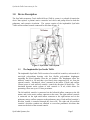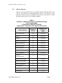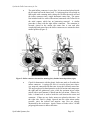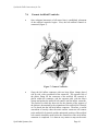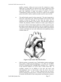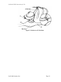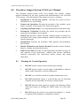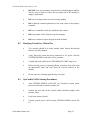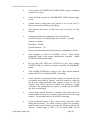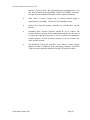
1
SynCardia Systems Inc. temporary Total Artificial Heart (TAH-t) INSTRUCTIONS FOR USE 1992 E. Silverlake Road Tucson, AZ 85713 USA (520) 545-1234 (866) 771-9437 STERILE EO CAUTION: Federal (USA) law restricts this device to sale by or on order of a physician. 0086 16 MAY 2005 950000-001 Rev. 004 SynCardia TAH-t Instructions for Use Table of Contents Page 1.0 Device Description.…………………………………………...…... 1.1 Implantable TAH-t…………………………...………...…… 1.2 External Console………………………………….….......... 3 3 4 2.0 Indications for Use………………………………………....…..… 4 3.0 Contraindications………………………………………………... 4 4.0 Warnings ...........................………………………………………. 5 5.0 Precautions……………………………………………........…..... 6 6.0 Summary of Clinical Study……………………………………… 6.1 Trial Success……………………………………………….. . 6.2 Hemodynamics……………………………………………….. 6.3 Adverse Events……………………………………………….. 6.4 TAH-t Reliability……………………………………………….. 7 7 7 8 9 7.0 Implant Procedures.......................................................................... 7.1 Materials Needed but not Provided………………………… 7.2 Preparation.............................................................................. 7.3 Removal of Native Ventricles................................................. 7.4 Preparing the Atria................................................................... 7.5 Outflow Connectors.................................................................. 7.6 Connect Artificial Ventricles.................................................... 10 10 11 11 13 15 16 8.0 Operator’s Manual for Console………………………………… 8.1 Warnings for Console Operation…………............................. 8.2 Readying Console for Clinical Use............................................ 8.3 TAH-t Startup Procedure...................................................……… 20 20 21 21 9.0 Explant Procedures…………………………………...……...…… 23 10.0 System Components............................................................................. 24 Appendix A: Patient Selection and Management……………………………….. Patient Selection...……………………………....…...…….……………… Anticoagulation………………………………..…......…………….....…... Exit Site…………………………………………………………………… 25 25 25 26 Appendix B: Outline of Training Program…………………………………….. 27 Appendix C: Materials Matrix…………………………………………………… 28 SynCardia Systems, Inc. Page 2 SynCardia TAH-t Instructions for Use 1.0 Device Description The SynCardia temporary Total Artificial Heart (TAH-t) system is a pulsatile biventricular device that replaces a patient's native ventricles and valves and pumps blood to both the pulmonary and systemic circulation. The system consists of the implantable SynCardia TAH-t and an external console connected by drivelines (Figure 1). Figure 1: SynCardia TAH-t System 1.1 The Implantable SynCardia TAH-t The implantable SynCardia TAH-t consists of two artificial ventricles, each made of a semi-rigid polyurethane housing with four flexible polyurethane diaphragms separating the blood chamber from the air chamber. The diaphragms allow the artificial ventricle to fill and then eject blood when compressed by air from the external console. Mechanical valves, mounted in the inflow (27mm) and outflow (25mm) ports of each artificial ventricle, control the direction of blood flow. The maximum dynamic stroke volume of each ventricle is 70 ml, which allows for generating a flow rate up to 9.5 liters per minute. The left artificial ventricle is connected via the left atrial inflow connector to the left atrium, and via the aortic outflow connector to the aorta. The right artificial ventricle is connected via the right atrial inflow connector to the right atrium and via the pulmonary artery outflow connector to the pulmonary artery. Each artificial ventricle’s driveline conduit is tunneled through the chest wall. The right and left artificial ventricle’s driveline conduits are attached to seven-foot pneumatic drivelines that connect to the back of the external console. SynCardia Systems, Inc. Page 3 SynCardia TAH-t Instructions for Use 1.2 The External Console The external console operates and monitors the SynCardia TAH-t. The console includes a monitoring computer that provides noninvasive diagnostic and monitoring information to the user. Device rate, dynamic stroke volumes, and calculated cardiac outputs are displayed on a beat-to-beat basis. Drive pressure and flow waveforms, along with cardiac output trends are provided. Patient related alarms (e.g., low cardiac output) are also displayed on the computer screen. A separate alarm panel on the console provides information on critical drive pressure and backup air and battery status. In addition, an alarm is generated if the computer is not monitoring the patient. All alarms generate audio and visual feedback to the user. A backup air supply (two air tanks) and electrical power (backup power supply and console battery) are automatically activated if the external compressed air and/or AC power are interrupted. This can occur during patient transport or in the event of a failure in the hospital’s air or electrical supply. The controller is the major component of the external console, and supplies pulses of pneumatic pressure to the right and left drivelines, which connect into the air chambers of the respective implanted artificial ventricles. These pulses cause the diaphragms to distend and thereby eject blood from the right artificial ventricle into the pulmonary circulation (typically 50-70mmHg) and from the left artificial ventricle into the systemic circulation (typically 180-200mmHg). 2.0 Indications for Use The SynCardia temporary Total Artificial Heart (hereinafter called the TAH-t) is indicated for use as a bridge to transplantation in cardiac transplant-eligible candidates at risk of imminent death from biventricular failure. The SynCardia TAH-t System is intended for use inside the hospital. 3.0 Contraindications The SynCardia TAH-t is contraindicated for use in: Patients who are not cardiac transplant eligible. Patients who do not have sufficient space in the chest area vacated by the natural ventricles. Generally this includes patients who have body surface areas <1.7m², or who have a distance between the sternum and the 10th anterior vertebral body measured by computed tomography imaging (CT scan) < 10 cm. Patients who cannot be adequately anticoagulated on the TAH-t. SynCardia Systems, Inc. Page 4 SynCardia TAH-t Instructions for Use 4.0 Warnings 1) Setup and operation of this device should only be undertaken by personnel trained in accordance with the SynCardia training program. A thorough understanding of the technical principles, clinical applications, and risks associated with the device is necessary. Prior to use, refer to this IFU and to the Circulatory Support System (CSS) User’s Manual for important operating instructions. 2) Sterile components of the SynCardia TAH-t are intended for single use only. Do not use if package is opened or damaged. Do not re-sterilize or reuse. 3) Safe use of this system has not been established in pregnant patients. 4) Do not subject patients implanted with the SynCardia TAH-t to magnetic resonance imaging (MRI) scans. 5) Safety and effectiveness in populations other than those of idiopathic and ischemic cardiomyopathies has not been established. 6) Do not use this device if the implantable artificial ventricles cannot fit in the chest area vacated by the natural ventricles. Inferior vena cava and left pulmonary venous compression are possible consequences. 7) Do not allow any catheter to get near the inflow valves of the SynCardia TAH-t. If a catheter gets into an inflow valve, the valve could become stuck, limiting flow. Confirm by x-ray after catheter insertion. A percutaneously inserted central catheter may migrate into the inflow valve when the patient raises his/her arm. 8) There is a potential for air embolism. De-air the artificial ventricles to minimize the possibility of air inadvertently entering the device. 9) Do not allow the external drivelines to become kinked. If there is any low cardiac output alarm, inspect the external drivelines for kinking. 10) A reduction in the maximum stroke volume on the external console’s monitoring computer to below 50 milliliters may indicate a failure of one of the diaphragms in an artificial ventricle of the SynCardia TAH-t. SynCardia Systems, Inc. Page 5 SynCardia TAH-t Instructions for Use 5.0 Precautions 1) Measures should be taken to prevent infection or sepsis. Use strict aseptic techniques during implantation. 2) The outflow grafts must be pre-clotted before use. 3) When closing the chest, a reduction in device output may indicate inflow obstruction. Reposition the artificial ventricles by anchoring to a rib or moving into the left plural space. 4) Do not use an antifibinolitic agent like Aprotinine or Amicar with an active clotting agent like FEIBA. 5) Use only water-soluble antiseptic cleaners around the exit site. Ointments may delay tissue in-growth into the driveline conduits. 6) Each external console contains a primary and a backup controller. An additional external console should also be available for use. 7) A sudden reduction in SynCardia TAH-t flow may be due to a kink in the pneumatic drivelines, or some inflow obstruction to the TAH-t, such as tamponade. Defibrillation or CPR will not be effective. 8) Flows should be kept at a reasonable output so that proper washing of the ventricles is established. SynCardia Systems, Inc. Page 6 SynCardia TAH-t Instructions for Use 6.0 Summary of Clinical Study The multi-center (5) clinical study focused on use of the SynCardia TAH-t as a bridge to cardiac transplantation in transplant eligible patients at risk of imminent death from biventricular failure. Ninety-five patients (ages 16-67) were implanted with the SynCardia TAH-t; 81 (70 males, 11 females) met all inclusion/exclusion criteria and were designated the core implant group. All patients were in NYHA Class IV at time of enrollment. Additional characteristics of the core implant group at the time of entry into the study are: 1) 15 patients were on heart-lung machine/ECMO support, 2) 51 patients had central venous pressure > 18 mmHg, 3) 11 patients had right ventricular ejection fraction < 20%, and 4) all patients had relative or absolute contraindications to VAD support as evidenced by refractory arrhythmias or unresuscitatable cardiac arrest (25), hypokinetic right/left/global ventricles (23), aortic regurgitation, stenosis or prosthesis (13), massive myocardial infarction or direct myocardial injury that affects technical insertion of a VAD through the left ventricle (10), failure to wean from cardiopulmonary bypass with bi-ventricular injury (4), left, right ventricular or mural thrombus (3) or septal defect (3). All patients were on maximal medical therapy and at imminent risk of death before a donor heart could be obtained. 6.1 Trial Success Treatment success was defined as patients who, at 30 days post transplant, were 1) alive; 2) NYHA Class I or II, 3) ambulatory; 4) not ventilator dependent; and 5) not on dialysis. Trial success was achieved in 56 (69%) of the 81 core patients. Sixty-four of the 81 core patients (79%) reached transplant after a mean time of 79 days (range 1-414). Fifty eight (72%) survived to 30 days post transplant. 6.2 Hemodynamics The hemodynamic performance of the SynCardia TAH-t was assessed through a comparison of pre- and post-implant values of cardiac index, systolic arterial blood pressure, and central venous pressure. Hemodynamic indices were effectively restored to near normal values. Average cardiac index increased from 1.9 to 3.0 L/min/m², average systolic blood pressure increased from 93mmHg to 120mmHg, and average CVP decreased from 20mmHg to 14mmHg. The average perfusion pressure (mean aortic pressure minus CVP) increased from 49mmHg to 63mmHg, which was associated with recovery of renal and hepatic function. SynCardia Systems, Inc. Page 7 SynCardia TAH-t Instructions for Use 6.3 Adverse Events Adverse events collected for all 81 core patients while on the SynCardia TAHt device are presented in descending order below. The adverse events represent 17.6 device years of experience for an overall event rate of 1.9 events per month while on the device awaiting transplant. Table 1 Incidence of Adverse Events in Core Patients During Device Implantation, in Decreasing Order of Frequency (Represents 17.6 years or 6411 days on the device) Number of Events Number (%) of Patients n=81 Any Adverse Event 400 76 (93.8%) Infection 125 58 (71.6%) Bleeding 55 34 (42.0%) Respiratory Dysfunction 44 24 (29.6%) Hepatic Dysfunction 30 29 (35.8%) Neurological Event 26 20 (24.7%) Renal Dysfunction 23 21 (25.9%) Reoperation 18 17 (21.0%) Device Malfunction 18 15 (18.5%) Peripheral Thromboembolism 14 9 (11.1%) Reduced Blood Pressure 13 12 (14.8%) Reduced Cardiac Index 11 7 (8.6%) Technical/Procedural 11 3 (3.7%) Fit Complication 5 5 (6.2%) Hemolysis 3 3 (3.7%) Miscellaneous 3 3 (3.7%) Adverse Event SynCardia Systems, Inc. Page 8 SynCardia TAH-t Instructions for Use 6.4 SynCardia TAH-t Reliability: Reliability testing was conducted to determine with reasonable assurance how long a device would perform as intended, without failure. Three separate sets of in vitro reliability testing were conducted. In one test, four TAH-t units were run for a period of 180 days. During this time there were no failures or abnormalities observed. In a second in vitro reliability trial, four TAH-t units were tested in a “run to failure” study design and are ongoing. After 35 months of testing, there were no failures or abnormalities observed. A third test was initiated using three TAH-t units which had expired their 3 year sterilization expiration date. This provided information about the effects of long-term storage on the fatigue resistance properties of the TAH-t. After 24 months of testing, there were no failures or abnormalities observed. In conclusion, a total of eleven units have been run for various lengths of time over the last six years with no device-related failures. The cumulative number of days used for calculation was 6715 and there have been no failures or signs of appreciable wear observed. When the 11 units are used to calculate reliability with a 90% confidence, the reliability at 30, 60 and 365 days is as reported in the table below. Table 2 Reliability Test Results with 90% Confidence # days run MTBF* 6715 2916 SynCardia Systems, Inc. Reliability in number of days run 30 60 365 0.99 0.98 0.88 Page 9 SynCardia TAH-t Instructions for Use 7.0 Implant Procedures This section contains the Implant Procedures. Patients receiving the SynCardia TAH-t are prepared for the implant per standard hospital procedures for any cardiac surgery. An arterial line, a central line, and standard artificial ventilation are required prior to the start of surgery. Transesophogeal echocardiography is recommended. 7.1 Materials Needed but not Provided • • 7.2 Three 15 by 20 centimeter sheets of membrane are used to create a neopericardium to prevent adhesions. Teflon felt buttresses strips. These are cut to approximately 10-12 mm in width and are generally 10 cm in length. It most often takes at least two of these to extend around the entire atrial cuff. (See Section 7.3) Preparation • • • • • • Pass the SynCardia TAH-t sterile components into the sterile field. After a standard median sternotomy is performed and before starting heparin, 1) prepare the arterial outflow connectors, 2) trim atrial inflow connectors to appropriate size, and 3) tunnel the artificial ventricle conduits through the skin. Preclot the two arterial outflow connectors three times with the patient's blood before giving the heparin. After exposure to the blood (approx. 30 cc for each connector each time) stretch connector, let dry for about 5 minutes and preclot again. The connectors are coated on the outside with biologic glue (cryoprecipitate with calcium and topical thrombin). Stretch again and let dry. This is done before cannulation so there is plenty of time to obtain sufficient preclotting of the outflow connectors. If the patient has been heparinized before deciding to implant the SynCardia TAH-t, the arterial outflow connectors should be preclotted with a combination of heparinized blood, protamine, and thrombin. Trim the two inflow connectors. Cut edges of the atrial quick connects for the atrial anastomoses to a radius extending out from the connector for 5-7 mm. Cut in a completely circular fashion. Then stretch and invert them. Pass the drivelines conduits through their subcutaneous pathways before heparinization of the patient. Position the left-sided ventricle conduit in the epigastrium at the level of the midclavicular line and approximately 2 inches below the costal margin. Make a semicircular skin flap incision on the left midclavicular line approximately 5 to 10 cm below the costal margin. Place a long clamp through the subcutaneous tissue, rectus fascia, rectus muscle, and into the chest as a chest tube would be placed. Use a similar approach to place the driveline conduit for the prosthetic right SynCardia Systems, Inc. Page 10 SynCardia TAH-t Instructions for Use • 7.3 ventricle, approximately 4 to 5cm medial to the left ventricle conduit so that no necrosis between the two exit sites will result. Enlarge pathway by opening the clamp and inserting a 1-inch Penrose drain through the pathway. Place the end of the conduit in the Penrose drain and advance approximately 8-10 cm. Pull Penrose drains through the pathway that delivers the driveline conduit. Position the artificial ventricles lateral to the wound and cover with a towel while the rest of the procedure takes place. This provides ample opportunity for small bleeders in the driveline pathway to clot. Removal of the Native Ventricles • Cannulation of the aorta and both superior and inferior vena cava is done in a standard fashion. Umbilical tape chokers are used on the cavae. Dissection around the aorta and pulmonary artery is limited to the proximal portion of the aorta in anticipation of transplantation, thus leaving some untouched areas that will not be very fibrotic. Cardiopulmonary bypass is instituted and the heart is fibrillated. Total bypass is instituted by pulling on the choker tapes. • The heart is fibrillated and excision of the heart begun. The excision is different from that used for transplantation. It seeks to preserve the annulus of both the tricuspid and mitral valves. Thus, an incision is made on the ventricular side of the AV groove of the right ventricle (Figure 2). Figure 2: First Incision of Ventricle Excision SynCardia Systems, Inc. Page 11 SynCardia TAH-t Instructions for Use • Incision can be done with a knife and extended with a knife or scissors. It is extended anteriorly across the right ventricular outflow tract and just proximal to the pulmonary valve. Posteriorly, it is extended to the interventricular septum and across the septum, staying on the left side of the arterioventricular (AV) groove and preserving the entirety of the mitral annulus. The anterior and posterior lines of incision are dissected apart from each other out to the level of the pulmonary bifurcation. • Trim the excess muscle on the right and left sides down to near the AV valves. All chordae are trimmed away, and a 2 mm edge of valve tissue along with the annulus is left intact. The atrial cuff generally extends 1 cm beyond the AV valves and consists of residual ventricular muscle and fat in the AV groove. The portion of the cuff in the left ventricular outflow tract consists of the residual anterior leaflet of the mitral valve and some aortic tissue. Most of the aortic tissue is trimmed away; however, some is left intact because it is felt to present strong tissue for the sewing of the inflow connector. The great vessels are then separated from the remaining ventricular myocardium above the valvular level. The great vessels are separated from each other (Figure 3). Figure 3: Ventricles Removed Over-sew the coronary sinus entrance into the right atrium. This prevents backflow of blood through the coronary sinus and out to the cut vessels on the AV groove. SynCardia Systems, Inc. Page 12 SynCardia TAH-t Instructions for Use • 7.4 Three 15 by 20 centimeter sheets of membrane are used to create a neopericardium to prevent adhesions. On the right side a sheet is anchored with non-absorbable suture to the pericardial reflection at the level of the superior vena cava, pulmonary veins and inferior vena cava. On the left side, a second sheet is sutured to the pericardial reflection just anterior to the left pulmonary veins. On the diaphragmatic side, a third sheet is sutured so as to cover the entire diaphragmatic pericardial surface. The 3 sheets are then folded upon themselves to keep them out of the operative field while the SynCardia TAH-t is implanted. Preparing the Atria The outer walls of the entire right and left atrial cuff complex are encircled with Teflon felt buttresses. These are placed in such a way that they can be used for strengthening the anastomosis to the inflow connector and also to tamponade and control all possible bleeding from the AV groove portion of the connector. These are cut to approximately 10-12 mm in width and are generally 10 cm in length. It most often takes at least two of these to extend around the entire atrial cuff. They are placed on the outer edge of the cuff and sewn in place with a running 3-0 polypropylene (Figure 4). A long needle is used to accomplish this (MH needle) and, after completing this, the left and right atrial cuffs are surrounded by Teflon felt buttresses. Figure 4: Atrial Sutures SynCardia Systems, Inc. Page 13 SynCardia TAH-t Instructions for Use • The atrial inflow connector is sewn first. It is inverted and placed inside the left atrial cuff on the lateral wall. 3-0 polypropylene is used with an MH needle with a running stitch, taking care to tailor the atrial cuff and the inflow connector into a single hemostatic suture line. The suture line includes both free walls of the atrium, buttressed with Teflon felt in the atrial septum, which has no buttressing material. A similar procedure is done with the right inflow connector. The connector is inverted, placed in the atrium, the suture line is run, and after completing both suture lines, the inflow connectors are returned to their normal position (Figure 5). Figure 5: Inflow connector inverted for suturing (left), finished normal position (right) • Check for hemostasis with the plastic leak tester made to fit within the inflow connector. A syringe (60-100 cc) is used to inject into a threeway stopcock connected with the tester to test the left atrial suture line. The surgeon places his hand posterior to the left atrium and compresses the right and left pulmonary veins, while the assistant injects saline mixed with a small amount of blood into the left atrium. Observe for leaks. A dental tool is used to break the seal between the tester and connector. If there are any leaks, sutures are placed at this time. On the right side, fluid is simply injected into the right atrium under pressure, since the inferior and superior vena cava are already obstructed by the caval tapes. Again, closure of leaks with a 3-0 MH polypropylene suture is done at this time. SynCardia Systems, Inc. Page 14 SynCardia TAH-t Instructions for Use 7.5 Outflow Connectors • Great vessel connections are made. The pulmonary artery anastomosis is made first. The lengths of the outflow connectors are determined by placing the artificial ventricles in position within the pericardial cavity. Place the outflow connector between the aortic or pulmonic valve and its respective great vessel and measure the distance. Cut outflow connectors to the appropriate lengths, usually 3 to 5 cm. • The pulmonary artery anastomosis is made with a running 4-0 polypropylene suture in an end-to-end fashion, beginning with lateral wall and running the back wall of the anastomosis from the inside (Figure 6). Figure 6: Outflow Connector Suturing • A similar anastomosis is made with the aortic suture line. Then, the outflow connector leak tester is used, which is inserted into the aortic outflow connector. Saline is injected under pressure, observed for leaks, and then any leaks are closed with a 4-0 polypropylene suture. The pulmonary artery needs to be cross-clamped in order to test the integrity of the pulmonary artery to connector anastomosis. The pulmonary artery and aortic tester is the same, but smaller, than the one utilized for the atrial inflow connector. SynCardia Systems, Inc. Page 15 SynCardia TAH-t Instructions for Use 7.6 Connect Artificial Ventricles • Once adequate hemostasis of all suture lines is established, placement of the artificial ventricles begins. First, the left artificial ventricle is connected (Figure 7). Figure 7: Connect Ventricles • Grasp the left inflow connector with two large Mayo clamps placed side by side, with a good hold of the connector. The opposite side of the plastic fitting for the connector of the artificial left ventricle is placed within the connector, and the operator pulls with the Mayo clamps and pushes the artificial left ventricle into the inflow connector. The position in which the heart sits for the duration of the support of the patient is determined by the orientation of the artificial left ventricle as it is placed into the left atrial inflow connector. Therefore, a careful assessment of exactly where the aortic outflow connector will connect to the artificial left ventricle and the anticipated position of the artificial left ventricle should be made before the connection of the atrial inflow connector is completed. It is then an easy matter to snap on the aortic SynCardia Systems, Inc. Page 16 SynCardia TAH-t Instructions for Use outflow connector, taking care not to twist the connector or aorta. While this is being done, the artificial left ventricle should be filled with saline through the aortic valve as well as the outflow connector. Once the connection is made, the patient is placed in a steep Trendelenburg position and large vent sites are placed in the highest point of the aortic outflow connector and the aorta for removal of air. • The artificial right ventricle is then connected. The atrial connection is made first, again taking care with the orientation of the artificial right ventricle so that the direction of flow from the outlet valve is appropriate for the anatomy of the patient. After the atrial connection is made, the pulmonary outflow connection is made, again, taking care not to twist. Before connecting the pulmonary outflow connector graft, the chokers on the superior and inferior vena cava should be removed. This allows a flow of blood into the right atrium and the right artificial ventricle, and flushes air out as the connection to the pulmonary artery is made (Figure 8). Figure 8: SynCardia TAH-t Final Position • With the patient in extremely steep Trendelenburg position and lungs being slowly ventilated, begin pumping at a very slow rate (40 BPM, 40%SYS, 180mmHg-LDP, 60mmHg-RDP, 0mmHg-VAC). Agitation of the artificial ventricles, as well as atria, is done at this time. If available, monitor for air bubbles in the atria and aorta with transesophageal echo to help decide when the device has been completely de-aired. As air is slowly removed from the device, increase pumping rate and pressure. Generally, this process takes about 10 minutes and should be done with patience and attention to remove SynCardia Systems, Inc. Page 17 SynCardia TAH-t Instructions for Use air before the SynCardia TAH-t takes over from the heart-lung machine. Decrease flow on the heart-lung machine temporarily to help move air through the lungs and into the device. Once satisfied that all air is out of the device, close vent sites and begin full pumping as the heart-lung machine is weaned off. The patient should be kept in steep Trendelenburg for an additional 15-20 minutes. • As the table is flattened out, try to position the artificial ventricles within the mediastinum. The pleura on both sides should not be opened and the pericardium should be left intact for closure. In smaller patients, there may be a need to force the right ventricle under the left edge of the sternum. Care should be taken to examine the left pulmonary veins and the inferior vena cava for evidence of compression. This is facilitated with trans-esophageal echo. • Check for hemostasis. After protamine has been administered and hemostasis obtained, a trial closure of the sternum is done using towel clips. If the fit of the device is judged adequate by hemodynamic stability and by transesophageal echo examination of the caval and pulmonary venous flows, reopen the chest and bring together the edges of the Gortex sheets to form a tent or neo-pericardium. Take care to make a loose fit, without impingement upon the cavae and tension on the device. Prior to closure of the cephalic part of the neo-pericardium, pass a rectangular piece of Gortex membrane around the proximal ascending aorta and anchor with non-absorbable suture. This is to provide a surgical plane at explant between the aorta and pulmonary artery to facilitate encircling and cross clamping the aorta. • One chest tube is placed in the neo-pericardium and a second in the native pericardial space. Irrigate with antibiotic solution before closure. Close the sternum and remaining incision in a routine fashion. Check device output, central venous pressure, and device filling when the chest is closed, because chest closure may alter the anatomy, causing pressure on the left-sided pulmonary veins, inferior vena cava, and occasionally the right-sided pulmonary veins. If decreased flow is noted, the chest must be reopened and changes made in the position of the device. One change has been to mobilize the diaphragmatic attachment of the pericardium, allowing the device to sit more leftward in the chest. This requires opening the left pleura, allowing the SynCardia TAH-t to slightly migrate into the left pleural space. If decreased flow is still observed, the right artificial ventricle may need to be anchored to a rib using umbilical tape (Figure 9). SynCardia Systems, Inc. Page 18 SynCardia TAH-t Instructions for Use Figure 9: Solution to a Fit Problem SynCardia Systems, Inc. Page 19 SynCardia TAH-t Instructions for Use 8.0 Circulatory Support System (CSS) User’s Manual The Circulatory Support System (CSS) User’s Manual, Part #950001, contains detailed information on the setup, operation and troubleshooting of the SynCardia TAH-t system. A brief description of the contents is given as a reference. Introduction to the External Console: Describes the system overview, indications for use, and warnings. Features and Operations: Describes the operation of the controller, power supply, air supply, vacuum pump, UPS, alarms and computer. Unpacking and Initial Setup: Covers unpacking instructions and initial setup. Performance Verification: Describes the console test procedure and the preparation for standing by for an implant. Clinical Use: Describes console operation, readying system for clinical use, SynCardia TAH-t startup, patient transport, transfer to backup controller, and console replacement. Specifications: Describes the SynCardia TAH-t physical and performance specifications. Routine Maintenance and System Checkout: Describes console checkout, batteries, cleaning, and checkout procedure. Field Service Guide: Describes air tank replacement, scheduled servicing, air tank connector O-ring replacement, controller pilot pressure calibration, controller replacement, fuse replacement, inactive storage, and crating instructions. 8.1 Warnings for Console Operation • DO NOT operate or adjust system without proper training. • DO NOT operate console on an air supply of substandard or unknown quality, either from tanks or in-house compressors. • DO NOT use a controller outside of its planned maintenance cycle. • DO NOT intentionally operate a system having only one functional controller for any longer than is necessary to switch systems. • DO NOT defeat the alarm system by turning it off, tampering with the alarm mute button, by muffling the audible alarms, or by any other means. • DO NOT expose the system to any unusual environment, i.e. electric or magnetic fields, dampness or temperature extremes. SynCardia Systems, Inc. Page 20 SynCardia TAH-t Instructions for Use 8.2 8.3 • DO NOT leave key in primary controller key switch during an implant. The key may be kept on Velcro near top right side of the backup air supply compartment. • DO have a backup system in a state of ready standby. • DO set backup controller parameters to the same values as the primary controller. • DO have a controller switch key attached to the console. • DO keep system casters locked except for transport. • DO have a number of spare charged air tanks on hand. Readying Console for Clinical Use • Two consoles should be in ready standby mode. Ensure that backup batteries are fully charged. • Verify that each system has been connected to AC power with the SYSTEM POWER switch in the ON (1) position • Confirm that each controller AC POWER/BATT CHRG lamp is on. • Before moving system to Operating Room, moisten a clean cloth with an antibacterial agent and wipe down all exterior surfaces of the console. • Do not spray any cleaning agent directly on system. SynCardia TAH-t Startup Procedures • Turn SYSTEM POWER switch OFF (0); disconnect system mains power cord and move system to patient site. • Position the rear side of the console within driveline length of the patient’s chest. • Lock front casters (wheels). • Connect system power cord and turn SYSTEM POWER switch ON (1). SynCardia Systems, Inc. Page 21 SynCardia TAH-t Instructions for Use • Verify console AC POWER and CHARGE LEDs are green, indicating system has AC power. • Verify that both controller AC POWER/BATT CHRG indicator lights are on. • Connect main air supply and verify pressure is 50–110 psi (340-575 kPa) at system power interface panel gauge. • Open primary and reserve air tank valves and verify they are fully charged. • Set primary and backup controllers to values listed below: Left Drive Pressure = 0 mmHg; Right Drive Pressure = 0 mmHg Vacuum = 0 mmHg Heart Rate = 40 bpm Systolic Duration = 33% Be sure vacuum remains off until the patient’s mediastinum is closed. • Turn computer on. Wait for WCOMDU to load. Select Patient Monitoring Mode. Enter patient identification requested. Inhibit WCOMDU alarms during startup. • Be sure that LDP, RDP and VACUUM are zero. Turn primary CONTROLLER key switch On and press controller ALARM RESET button. • Turn ALARM SYSTEM key switch to ON. Mute console hardware alarms until LDP > 90 mmHg and RDP > 20 mmHg. • Verify controller is operating normally; connect left ventricle driveline to controller upon order by surgeon. After left ventricle is connected and de-aired, await instructions from surgeon to start. To start left ventricle, raise LDP to about 100 mmHg. You should see a slight overload of the cardiopulmonary bypass waveform and WCOMDU may show a small output. • Connect right ventricle driveline to controller. After right ventricle is connected and de-aired, await surgeon’s instructions to start the right ventricle. To start right ventricle, raise RDP to 40 mmHg. • As the perfusionist begins to slow venous return, SynCardia TAH-t filling should increase. As filling increases, adjust drive pressures, heart rate and systolic duration to prevent full fill and to provide full ejection. Normal range is LDP= 170-210 mmHg, RDP= 60-100 SynCardia Systems, Inc. Page 22 SynCardia TAH-t Instructions for Use mmHg, % Systole=50-60. Be vigilant during the weaning process, you may need to make rapid adjustments. Observe WCOMDU waveforms for signs of flow obstruction and other cardiac output information. • After chest is closed, vacuum may be started (normal range is approximately 10 mmHg). Do not exceed 30 mmHg vacuum. • Remove key from the primary controller key switch before moving patient. • Pneumatic drive ejection pressures should be set to achieve full ejection. Pressure tracings on the monitoring computer can be viewed to assure the right drive pressure is set to overcome the pulmonary systolic pressure, and the left drive pressure is set to overcome the aortic systolic pressure. • The SynCardia TAH-t rate should be set to achieve a stroke volume between 50 and 65 milliliters on the monitoring computer. SynCardia TAH-t beat rates should be between 100 and 130 beats per minute. SynCardia Systems, Inc. Page 23 SynCardia TAH-t Instructions for Use 9.0 Explantation Procedures Explantation of the device should be handled like any other redo cardiac procedure. Great care should be taken in the separation of the sternum from the device, the great vessel connector, and the drivelines. Explantation may be easier if the device is covered with a Gortex membrane. Cardiopulmonary bypass is initiated with dual caval cannulation with tourniquets, the aorta is cross-clamped, and the SynCardia TAH-t is turned off. The artificial ventricles are separated from the atrial inflow cannula. The great vessels outflow connectors are amputated at the level of the connector/great vessel anastomosis. The artificial ventricles are transected at the base to the driveline conduit connection, and the SynCardia TAH-t is removed from the operating field. The driveline conduits are pulled through the skin. The remaining atria inflow connectors are still in the remaining portion of ventricular muscle where they were initially sutured. They are removed by transecting the AV groove throughout. The remaining atria and great vessels can now be trimmed to accept the donor heart. SynCardia Systems, Inc. Page 24 SynCardia TAH-t Instructions for Use 10.0 System Components The SynCardia TAH-t system is comprised of the following: • Implant Kit - Part # 500101 (Sterile) Contains left artificial ventricle, right artificial ventricle, 2 inflow connectors, 2 outflow connectors, and an ancillary pack with drivelines, inflow pressure test plug, outflow pressure test plug, locking ties, and 2 de-airing needles (all sterile). All sterile components are packaged in double aseptic transfer packages. • Surgical Spares Kit - Part # 500177 (Sterile) Contains inflow connector, outflow connector, drivelines, inflow pressure test plug, outflow pressure test plug, and locking ties. • Circulatory Support System (External Console) – Part # 400207 (Non-sterile) • Air Tank - Part # 390004 (Non-sterile) There should be two complete implant kits, one surgical spares kit, two circulatory support systems and eight air tanks. SynCardia Systems, Inc. Page 25 SynCardia TAH-t Instructions for Use Appendix A Patient Selection and Management Management and coordination of successful SynCardia TAH-t support requires a multidisciplinary team that has experience with circulatory support systems. Teams can include surgeons, cardiologists, heart transplant coordinators, perfusionists, engineers, nurses, cardiac rehabilitation therapists and coagulation specialists. The following reports the experience and recommendation of the largest enrolling clinical site, University Medical Center, Tucson, Arizona. Patient Selection Successful bridge to transplant with the SynCardia TAH-t involves selecting patients who are transplant eligible and who additionally are assessed in two main areas: 1) evaluation of fit of the SynCardia TAH-t in the patient’s chest, and 2) evaluation of the potential for reversal of any end organ dysfunction. Once the SynCardia TAH-t is implanted, and there are no fit issues, flow is maximized through the TAH-t. The controller nominal settings are: left drive pressure of 180-220 mmHg, right drive pressure of 50-70mmHg, device rate of 110-130 BPM, percent systole of 50-55%, and diastolic vacuum of 8-12 mmHg. With these settings an average device output of 6.5-7.5 LPM should be achieved, with a CVP of 8-12 mmHg. The SynCardia TAH-t is specified for patients with body surface areas of at least 1.7 m². At a cardiac index of 2.5 l/min/m², the calculated flow would be 4.25 liters/min. This is the flow used to simulate hypotensive conditions tested during product reliability testing. The TAH-t console is pre-set with an alarm to indicate flows <3.5 l/min. With normalized hemodynamics, device outputs remain relatively constant, changing as the CVP fluctuates. This “Starling like response”, (where an increase in CVP fills the SynCardia TAH-t with more volume, which is ejected on the next beat, increasing device output), requires no controller adjustments. Constant device output and high flow under normal CVP provides washing of the artificial ventricles. Anticoagulation therapy The level of anticoagulation will vary depending on the patient’s coagulation status. In general, the patients require systemic anticoagulation, similar to that used for patients with mechanical valves. The following guidelines are recommended based on the experience of the largest enrolling clinical site, University Medical Center. Pre-operative baseline Obtain results of PT, PTT, bleeding time, TEG, platelet count, platelet aggregation studies and fibrinogen. Intra-operative period Heparinize for CBP per usual routine. Protamine may be used for reversal per usual routine. SynCardia Systems, Inc. Page 26 SynCardia TAH-t Instructions for Use Post-operative period (immediate) Start Dipyridamole at 100 mg -250 mg PO or NG every 6 hours. The dose is adjusted to balance platelet aggregation factors: keep collagen factor positive; keep ADP, epinephrine, arachnadonic acid factors negative. If all factors are positive, the dose of dipyridamole should be maximized. If only one factor other than collagen is positive, dipyridamole or ASA is increased until only collagen is positive. Platelet aggregation studies are checked twice per week. Start ASA when platelet aggregation shows any factor other than collagen is positive, usually within 24 hours post-operative. The ASA dose is started between 81-650 mg PO per day. If all platelet aggregation factors are positive and the dipyridamole is already started, 325 mg of ASA is used per day to start. If only one factor, other than collagen, is positive, ASA is started at 81 mg per day. The dipyridamole is adjusted according to the results of Platelet Factor 4 and Beta Thromboglobulin. If these tests are elevated, the platelets are very active and the dipyridamole needs to be increased. ASA is adjusted with the platelet aggregation and bleeding time studies. The bleeding time is kept between 10 - 20 min if possible. If the collagen is negative, too much dipyridamole or ASA is being given; daily dosages of one or both are decreased to prevent bleeding. Pentoxifylline 400 mg is started PO every 8 hours in the early post-operative period (2-3 days). Pentoxifylline may be increased if fibrinogen increased above normal. Post-operative (chest tubes pulled) Start IV Heparin at 25,000 units in 250 cc of D5W at 500-1000 units per hour, when chest tubes are discontinued. IV Heparin is continued to maintain PTT at 50-55 sec for 2 weeks, then converted to Coumadin to keep INR 2.5-3.5 or PT 18-22 sec, then IV Heparin is stopped. Exit Site Management Take care to keep driveline exit sites clean and dry. Infections should be treated according to hospital protocol. SynCardia Systems, Inc. Page 27 SynCardia TAH-t Instructions for Use Appendix B Outline of Training Program Operation of this device should only be undertaken by personnel trained in accordance with the SynCardia Training Program. The training will include the following topics: 1) Indications and Contraindications 2) System Overview 3) Implant Procedures 4) Operation of the console 5) Explant Procedures 6) Patient Management 7) Summary of Clinical Studies 8) Animal Procedure – a minimum of one implant needs to be performed. 9) Practical Experience - Physicians will be required to minimally view one live implant procedure or have their first procedure proctored. SynCardia will maintain centers of excellence where surgeons may view implantations. Further, proctors will be made available by SynCardia for surgical teams during their first case. SynCardia Systems, Inc. Page 28 SynCardia TAH-t Instructions for Use Appendix C Materials Matrix The SynCardia TAH-t ventricle components are manufactured from the raw materials as defined in the matrix below. The artificial ventricles have met the test requirements of ISO 10993, Biological Evaluation of Medical Devices. SynCardia TAH-t Patient Contacting Materials Matrix Component Ventricle and diaphragm Material Segmented polyurethane Nylon Inflow connector Segmented polyurethane Polyester fabric Outflow connector Segmented polyurethane Polyethylene material Valves Titanium and pyrolitic carbon (Medtronic Hall Heart Valves) Drivelines Polyvinyl chloride tubing ©2005-2010 Syncardia Systems, Inc. SynCardia Systems, Inc. Page 29