1
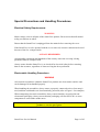
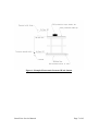
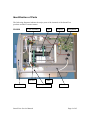
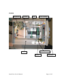
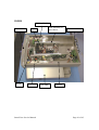
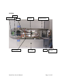
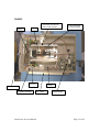
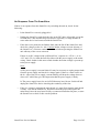
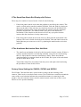
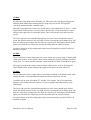
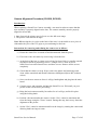
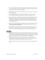
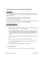
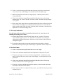
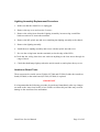
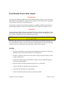
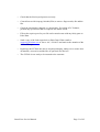
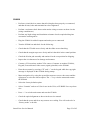
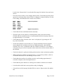
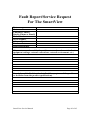
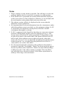
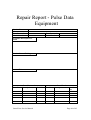
SmartView Service Manual V1.21
September 2002
Copyright Notice
All rights reserved. No part of this publication may be reproduced in any form
whatsoever without the express written permission of Pulse Data International Limited.
Every effort has been made to ensure that the information contained within this manual is
correct at the time of issue. Neither Pulse Data International Limited nor its agents
assume responsibility for errors or omissions in this information. No liability is assumed
for damages resulting from the use of this information.
Copyright © 2001 by Pulse Data International Limited, Christchurch, New Zealand.
SmartView Service Manual
Page 1 of 45
Contents
COPYRIGHT NOTICE ..........................................................................................1
CONTENTS ..........................................................................................................2
SERVICE POLICY ................................................................................................4
Service Agreement .............................................................................................................. 4
About This Manual.............................................................................................................. 4
Level of Servicing ............................................................................................................... 4
Technotes ............................................................................................................................. 5
Dealers Section of www.pulsedata.com............................................................................. 5
SPECIAL PRECAUTIONS AND HANDLING PROCEDURES .............................6
Electrical Safety Requirements........................................................................................... 6
Electrostatic Handling Procedures ..................................................................................... 6
IDENTIFICATION OF PARTS...............................................................................8
SV1000................................................................................................................................. 8
SV3000................................................................................................................................. 9
SV5000............................................................................................................................... 10
SV7000............................................................................................................................... 11
SV8000:.............................................................................................................................. 12
COMMON FAULTS AND REPAIR PROCEDURES ...........................................13
Introduction........................................................................................................................ 13
Specialist tools required for servicing SmartView Products .......................................... 13
No Response From The SmartView................................................................................. 14
If The SmartView Starts But Displays No Picture .......................................................... 15
If The Autofocus Mechanism Does Not Work................................................................ 15
Factory Setup Settings for SV8000, SV7000 and SV5000............................................. 15
Camera Alignment Procedure (SV1000, SV3000) ......................................................... 17
Camera Alignment Procedure (SV5000, SV7000, SV8000).......................................... 19
Lighting Assembly Replacement Procedure.................................................................... 21
Autofocus Board Tests...................................................................................................... 21
FINAL QUALITY CHECKS AFTER REPAIR .....................................................23
SV1000............................................................................................................................... 23
SV3000............................................................................................................................... 25
SV5000............................................................................................................................... 28
SV7000............................................................................................................................... 30
SmartView Service Manual
Page 2 of 45
SV8000............................................................................................................................... 32
SOFTWARE UPGRADE PROCEDURES...........................................................35
SV1000............................................................................................................................... 35
SV3000............................................................................................................................... 36
SV5000............................................................................................................................... 37
SV7000............................................................................................................................... 38
SV8000............................................................................................................................... 39
FAULT REPORT FORMS...................................................................................41
CONTACT INFORMATION ................................................................................45
SmartView Service Manual
Page 3 of 45
Service Policy
Service Agreement
It is envisaged that anyone using this manual, or servicing SmartView Products is
familiar with, and bound by, the distributors agreement between Pulse Data and the
Servicing Company. This agreement describes the required level of service, quality and
responsiveness required to meet the market expectation. The document also describes the
required reporting and warranty claim procedures.
It is strongly recommended that the Servicing Company be fully conversant with the
Distributors Agreement before attempting to service any Pulse Data product.
About This Manual
The approach to servicing contained within this manual is for major component
replacement rather than “board level” diagnosis.
This manual does not cover every single fault that could occur with the SmartView
products. It is intended as an introduction to the technical operation of the SmartView’s
as well as a brief introduction to the theory of operation and basic faults.
It is intended that this manual be utilized with Technotes, which are documents that
address specific technical issues to do with the product as noted below.
Level of Servicing
SmartView Servicing should be restricted to:
a) The replacement of modules
b) The correction of mechanical faults in joints, connectors and wiring.
Circuit diagrams have not been included in this manual. Faultfinding and repair at the
component level requires specialized equipment and knowledge and should not be
attempted.
SmartView Service Manual
Page 4 of 45
Technotes
Technotes are documents published by Pulse Data from time to time to address issues
relating to changes to products. Technotes can cover fixes to bugs, product enhancements
and notification of software upgrades.
Each Technote has a description of what as happened and the reasons for the change. The
Technote will also contain instructions for field upgrades (if required). Copies of all
Technotes as well as copies of Service Manuals are held on the Dealers section of the
Pulse Data website (http://www.pulsedata.com/csw). There is also a mailing list, which
will advise the publication of a new Technote. To subscribe to this list, please contact
[email protected].
Dealers Section of www.pulsedata.com
The Dealers section of the http://www.pulsedata.com/csw website is a restricted section
requiring password access. Within this site can be found copies of spare parts lists,
service manuals and Technotes as well as other dealer related information.
In order to be given access to this section of the website, please contact your local Pulse
Data distributor.
SmartView Service Manual
Page 5 of 45
Special Precautions and Handling Procedures
Electrical Safety Requirements
WARNING
Mains voltage exists in all parts of the SmartView product. Please ensure that all normal
safety precautions are taken.
Ensure that the SmartView is unplugged from the mains before removing the cover.
If the SmartView is to be operated with the cover removed, extreme caution must be used
because of the live voltages inside.
ALWAYS REMEMBER
All applicable regulations and standards of the country where the servicing is being
performed must be complied with.
Always ensure that the SmartView’s are checked for electrical safety before returning
them to the customer, regardless of what servicing has been performed.
Electrostatic Handling Procedures
WARNING
All electronic assemblies within the SmartView products are electrostatic sensitive and
can be damaged if not handled properly.
When handling the assemblies, always ensure a properly connected wrist or foot strap is
used, and that workbenches are electrostatically protected (refer to Figure 1 for examples)
When transporting electronic assemblies, always ensure that they are packed in nonelectrostatic packaging. Always ensure that the packaging will not flex PCB’s or cause
components to come under undue stress.
Failure to follow these procedures will void any warranty on the SmartView
product or service spare parts.
SmartView Service Manual
Page 6 of 45
Figure 1: Example Electrostatic Protected Work Station
SmartView Service Manual
Page 7 of 45
Identification of Parts
The following diagrams indicate the major parts of the internals of the SmartView
products and their common names.
SV1000
Lens Assembly
Inverter
Front Panel
SmartView Service Manual
Lens
Camera
Main Board
Table
Lighting Module
Chassis
Page 8 of 45
SV3000
Main Board
Camera
Lens Assembly
Lens
Lighting Module
Chassis
Inverter
SmartView Service Manual
Front Panel
Page 9 of 45
SV5000
Lighting Module
Front Panel
Mirror
Lens Assembly or
Sub-chassis
Lens
Inverter
SmartView Service Manual
XY Table
Connector Board
Chassis
Page 10 of 45
SV7000
Mirror
Mode button
Lens
Main Board
SmartView Service Manual
Camera
XY-Table
Light Housing
Base
Power Supply
Module
Page 11 of 45
SV8000:
Autofocus Board (on
side of sub-chassis)
Lens
Mirror
Inverter
Lens Assembly
or Sub-Chassis
Chassis
Front Panel
Lighting Module
SmartView Service Manual
XY Table
Main Board
Page 12 of 45
Common Faults and Repair Procedures
Introduction
The following list of fault symptoms is given as much as to create an understanding of
the operation of the SmartView units as it is to diagnose the “common” faults that can be
found on SmartView products.
It is assume d that before any of the following remedies are tried, some simple checks
such as making sure all connections are secure, are performed.
It is recommended that, where possible, the SmartView unit undergoing service is
compared to a new “out of the box” unit. In this way, any operation can be verified
against a good unit to see whether the behavior is normal.
Please note that the final quality checks noted at the end of this section must be
performed after any servicing has taken place and before the unit is returned to the
customer. This is to ensure that the unit performs well, is safe, and complies with the
regulations applicable to the country where the SmartView is serviced.
Specialist tools required for servicing SmartView Products
Most tools required to service SmartView products should be commonly available
through hardware or electronics outlets. However, the following list indicates some of the
tools that may nor form part of a standard tool kit, or are worthy of special mention.
•
•
•
•
•
•
•
•
•
Soldering iron with wide and narrow tips.
An IC remover (for socketed IC’s)
A 2mm right angled Allen key (for the colour camera)
A 1.5mm Allen key (for the 6:1 lens)
A miniature metric socket set with extensions.
A dongle for reprogramming SV8000’s (Available as a service part)
A socket suitable for D-SUB connector nuts.
A pair of vice grips suitable for gripping on to the 6:1 lens (in particular, the
grooved ring at the rear of the lens).
A TV pattern generator (NTSC format)
SmartView Service Manual
Page 13 of 45
No Response From The SmartView
If there is no response from the SmartView by switching the unit on, check for the
following:
•
Is the SmartView correctly plugged in?
•
Unplug the SmartView and check the fuse in the IEC inlet. All models except the
SV7000 have a fuse and this may have blown, especially if a large monitor or
some other device has been used with the SmartView.
•
If the above two points do not find the fault, take the lid off the SmartView and
check for voltages on the d.c. side. Caution: Mains voltages exist in all parts of
the SmartView’s. Extreme caution must be used when operating the SmartView
unit with any of the covers removed.
If there is no DC voltage inside (All SmartView’s operate on +12V d.c., or on
+12V and +5V d.c.) then the fault lies either with the power supply or the mains
wiring. Check further in this area to find whether the mains voltage is present up
to the power supply.
Note:
a) The power supply is current limited. It may be necessary to unplug output leads
from the power supply and check for voltage again. If there is a short circuit on
the d.c. side of the power supply, current limiting will drop the voltage down to
close to 0V which may give the impression that the power supply is faulty.
b) The power supply has a fuse on its PCB that may have blown. Switch off and
unplug the SmartView before checking the continuity of the fuse.
•
If the d.c. voltage is reaching the main board, it is most likely that the main board
is faulty. Turn off the SmartView, disconnect from the power and replace the
main board. Once the new board is fully re-connected and bolted in place, re-start
the SmartView to check if this was the problem.
SmartView Service Manual
Page 14 of 45
If The SmartView Starts But Displays No Picture
There may be a number of causes for this. Check for the following:
•
If the front panel controls work, then the problem is most likely the camera. This
can be verified on the Autofocus models (SV8000, 7000 and 5000) by placing an
object on the table. If the unit does not Autofocus, then turn off the SmartView,
disconnect from the power supply and replace the camera using the alignment
procedure noted below. The camera sends a sync pulse to the Autofocus
mechanism. If the Autofocus unit does not receive any sync pulse from the
camera, then the Autofocus circuitry cannot work.
•
If the front panel controls do not work, then it is likely that the main board is the
problem. This can be double checked on the SV8000, 7000 and 5000 because the
main lights may not come on as well. Try replacing the main board to solve this
problem.
If The Autofocus Mechanism Does Not Work
•
The Autofocus mechanism is driven by the Sync pulse from the camera. If there is
a picture and the SmartView is behaving normally, except for not Autofocusing,
then it is likely that the Autofocus mechanism is faulty. Please note that the
Autofocus Board is a separate board on the SV8000, but is part of the main board
on the SV5000 and SV7000.
Turn off the SmartView, disconnect from the power and replace the board using
the procedures of later in this section.
Factory Setup Settings for SV8000, SV7000 and SV5000
The SV8000, 7000 and 5000 have special modes to help with the centering of the
cameras. These involve cross hairs on the screen. The SV8000 has a small box around the
center of the cross hairs that indicates the permissible tolerance in centering for this
product. Also, the Autofocus units can have manual control on the lens to allow zoom
and focus to be operated manually.
SmartView Service Manual
Page 15 of 45
SV8000:
To enter this setup mode on the SV8000, you will need to have the Keypad plugged in.
Hold the mode button upon startup until two long beeps are heard. This puts the
Autofocus mechanism into a manual mode.
When the copyright notice can be seen on the screen, press and hold “CE” and “=” on the
keypad until a menu appears on screen. Move down to the “Zoom Lens Check” option
and press the right arrow to select this option. This will bring the cross hairs on to the
screen.
The focus and zoom are controlled through the size knob. Once started in the factory
mode, the default control for the size knob is Zoom. Pressing the preset button (you will
hear two short beeps) changes the Size knob to control focus. Pressing the Preset button
again (you will hear one long beep) puts the Size knob back in control of Zoom.
In order to break out of this setting and resume normal operation, turn the SV8000 off
and back on again.
SV7000:
The SV7000 has a similar setting but has a more simple way of activating it. Simply hold
in the square button on the remote control when starting the SV7000 until the cross hairs
can be seen. To resume normal operation, simply turn the SV7000 off and then on again.
The toggle switch on the remote control controls either zooms or focus. Pressing the
square button on the remote changes the toggle switch between zoom and focus.
SV5000:
The SV5000 has a factory mode which is activated by holding in the Mode button when
turning the unit on. Keep holding the button in until one long beep is heard.
Crosshairs can be seen on both the TV and the VGA outputs. The VGA output also
displays some numbers that are used for version recognition and other factory setup
information.
The focus and zoom are controlled through the size knob. Once started in the factory
mode, the default control for the size knob is Zoom. Pressing the preset button (you will
hear two short beeps) changes the Size knob to control focus. Pressing the Preset button
again (you will hear one long beep) puts the Size knob back in control of Zoom.
In order to break out of this setting and resume normal operation, turn the SV5000 off
and back on again.
SmartView Service Manual
Page 16 of 45
Camera Alignment Procedure (SV1000, SV3000)
Introduction:
When replacing a SmartView Camera Assembly, care must be taken to ensure that the
new assembly is properly aligned on the lens. The camera assembly must be properly
aligned to ensure that:
1. Once focused, the picture stays in focus over the full zoom range.
2. The picture is not tilted at an angle.
Note: When using the vice grips on the back of the lens, it is advisable to use a piece of
cloth under the jaws of the vice grips to prevent damage to the lens.
Instructions for removing and refitting the camera are as follows:
a) Ensure the SmartView is turned off and disconnected from the power.
b) First remove the old camera by unscrewing it from the lens.
c) At the back of the lens is a large grooved ring. In front of this is a smaller smooth
ring that is locked in position by screws. A single screw is used in recent
SmartViews but earlier SmartViews used three screws. Remove all the screws
completely.
d) Check that the camera is clean. If not, remove the plastic and metal rings and
clean with a cotton bud and SDA4F solution or Methylated Spirits WP (without
colour).
e) Screw on the new camera as far as it will go, hand tighten and plug into the main
board.
f) Connect power and a monitor and turn the SmartView on. Wait until you get a
picture on the screen before proceeding.
g) Bring the lens/camera assembly forward as far as it will go, and lock in place
using the locking knob.
h) Position a document under the camera. Set the "Size" control to maximum and
focus the image using the "Focus" control. During this step, don't worry about the
alignment of the picture.
i) Set the "Size" control to minimum and focus the image by rotating the camera and
allowing both lens rings to rotate.
SmartView Service Manual
Page 17 of 45
j) Fit the smooth ring's locking screw that is nearest to the top of the lens. There is
no need to fit the other two screws. Tighten the screw until it just catches. Make
sure that the "Focus" control still turns freely.
k) Repeat step h to see if the picture still looks good. If not, re-do the camera setup
from the beginning.
l) Hand tighten the locking screw. Repeat step h again as the camera may have
moved in tightening. Repeat any steps necessary if the camera has moved.
m) Position a grid target on the XY table using the rear lip of the XY table to ensure
that the paper is square. Use the KeyPad to display the horizontal line markers.
Slightly loosen the large grooved ring. Rotate the camera to align the picture
horizontally then firmly tighten the grooved ring while keeping the alignment of
the camera horizontal.
n) Move the lens/camera assembly to the back as far as it will go, lock in place and
check that everything still looks good by performing step h. Re-do the camera
setup if the quality is unacceptable.
o) When complete, use Loctite or lock lube to seal the camera setting position in
place. The correct positions will be noted on the camera that has been removed,
and the lens. Ensure that the liquid does not get into any other moving parts.
Final Check:
a) Slide the lens/camera assembly to the frontmost position and repeat steps a) to d)
to ensure that: the image stays focused and the image is square over the full range
from maximum to minimum magnification, without any adjustment to the camera.
Repeat the procedure above if the result found here is not satisfactory.
b) Fit the lid to the SmartView and, for the SmartView, slide the lens/camera
assembly from the frontmost position to the rearmost position to ensure that the
cable between the Controller board and the camera is free to move.
c) Slide the lens/camera assembly fully forward and lock in place using the locking
screw.
SmartView Service Manual
Page 18 of 45
Camera Alignment Procedure (SV5000, SV7000, SV8000)
1. Introduction
When replacing a SmartView Camera Assembly, care must be taken to ensure that the
new assembly is properly aligned on the lens. The camera assembly must be properly
aligned to ensure that:
1. Once focused, the picture stays in focus over the full zoom range.
2. The center of the picture stays in the center over the full zoom range.
3. The picture is not tilted at an angle.
In order to perform the camera setup effectively, the SmartView will need to be started in
its “factory mode” so that focus and zoom can be controlled manually.
2. The Alignment Procedure
2.1. The Focus Adjustment
a) Fit the new camera assembly to the lens but do not fully tighten the camera clamp
screw. Connect the camera to the Controller board.
b) For the SV8000, turn the unit on and press “CE” and “=” when the copyright
message is displayed. When the menu appears, select the “Test Camera” option.
A screen will appear after a few seconds. There are three tests performed. All tests
must pass for a camera to be suitable. If any test fails, reject and replace the
camera.
c) Start up the SmartView in factory mode to allow the manual control of focus and
zoom.
d) Zoom in to maximum magnification and then focus on the image.
e) Zoom out to minimum magnification and then focus the image by sliding the
camera along the lens barrel.
f) Repeat steps c) and d), then tighten the camera clamp screw.
2.2. Centering the Picture
a) Place a grid target (use a piece of 1/10 inch graph paper) on the XY table.
SmartView Service Manual
Page 19 of 45
b) Zoom in to maximum magnification and adjust the grid target to position the
cross at the center of the display over an intersection of the grid target.
c) Mark the particular intersection on the grid paper so that its position can be
clearly identified.
d) Zoom out to minimum magnification and check that the center of the image
remains static. An error of one half of a block in each direction of the grid target
is acceptable.
e) If the center of the image moves more than one half of a block of the grid, loosen
the CCD PCB mounting screws and adjust the PCB position to ensure that the
image remains static when the zoom is adjusted from maximum to minimum. Retighten the CCD PCB mounting screws.
2.3 The Angle Adjustment
Note: this part of the procedure is normally performed at the same time as the
centering of the image in 2.2 above.
a) Position the grid target on the XY table using the rear lip of the XY table to
ensure that the paper is square. For SmartView models that use the Keypad,
display the horizontal line markers. Otherwise, use the bottom of the monitor as
an alignment guide.
b) Loosen the camera clamp screw and rotate the camera assembly so that the
horizontal lines align to the grid on the display. Tighten the camera clamp screw.
2.4 The Final Check
a) Zoom in to maximum magnification and focus on the image.
b) Zoom out to minimum magnification ensuring that the image stays focused.
c) Using the grid target, zoom in to maximum magnification and adjust the grid
target to position the cross at the center of the display over an intersection of the
grid target.
d) Zoom out to minimum magnification and check that the center of the image
remains within one block of the grid target.
e) Using the grid target and the horizontal line markers, ensure that the horizontal
lines align to the grid on the display.
f) If the camera needs to be adjusted for any reason, repeat the final check procedure
starting at step a).
SmartView Service Manual
Page 20 of 45
Lighting Assembly Replacement Procedure
1. Make sure that the SmartView is unplugged.
2. Remove the top cover and save the 2 screws.
3. Remove the wiring loom from the Lighting Assembly inverter using a small flatblade screwdriver to loosen the terminals.
4. Remove the M3 nylock nut and screw attaching the lighting assembly to the chassis.
5. Remove the lighting assembly
6. Install the new lighting assembly and secure with the nylock nut and screw.
7. Re-wire the wiring loom into the terminals (red to the edge of the PCB)
8. Check that the wiring loom does not catch on anything as the lens moves through its
range of travel.
9. Check that both lamps light up when the unit it turned on, and replace the top cover.
Autofocus Board Tests
These tests must be carried out on SV8000, SV7000 and SV5000 if either the Autofocus
board (SV8000) or the main board (SV7000, SV5000) is replaced.
IMPORTANT
It is important that the following procedure be performed immediately after any changes
are made to the Auto focus board, or lens. Failure to follow this procedure may result in
damage to the Autofocus lens mechanism.
SmartView Service Manual
Page 21 of 45
1) Start up the unit being serviced and place it in Factory Mode.
2) Set the size knob to control focus. Run the focus through its range and watch the
motor (the front motor on the lens). Check that as it reaches each end of its range
that there is a small “bounce back”. This lets you know that the optical end stops
are working correctly. If the bounce back is not encountered, there is a
problem. Do not attempt to continue using the SmartView until the problem
can be diagnosed as this may cause damage to the lens motors.
3) Set the size knob to control zoom (the rearmost motor on the lens) and repeat the
test as for the focus motor. If the bounce back is not encountered, there is a
problem. Do not attempt to continue using the SmartView until the problem
can be diagnosed as this may cause damage to the lens motors.
4) If both these checks are OK, then the Autofocus unit is OK for use. Continue with
any other checks required, including a basic check to see whether the Autofocus is
working (you will need to turn the unit off and then on again to clear the
“manual” mode.
SmartView Service Manual
Page 22 of 45
Final Quality Checks After Repair
IMPORTANT
It is imperative that any technician servicing the SmartView product is conversant with
all requirements and standards required to be complied with according to the regulations
of the country where the servicing takes place.
No reference is made to any particular regulation or standard within this manual due to
the differing regulations in all of the countries where the SmartView product is sold.
WARNING
Do not attempt any High Voltage or Insulation Resistance test between the Phase (Live)
and Neutral of the input circuit of this product, or between Positive and Negative of the
DC circuitry as damage will occur to the internal circuitry.
The Warranty on the SmartView product, or service spares will be void if the above
tests are performed.
The following procedure is to be followed as a final quality check before returning any
serviced SmartView to the customer. Pulse Data recommends that a different technician
to the one who serviced the unit, where possible, performs these checks.
SV1000
•
Perform a visual check to ensure that all wiring has been properly re-connected,
and that all nuts, bolts and terminals have been tightened.
•
Perform a resistance check between the mains wiring to ensure no short-circuits
(using a multi-meter)
•
Perform any high-voltage and insulation resistance checks required taking into
account the warning above.
•
Plug the SV1000 in with all outputs and mains power connected.
•
Turn the SV1000 on and check for the following:
•
Check that the lens belts are neatly aligned.
•
Check for smooth operation of the focus and zoom knobs.
SmartView Service Manual
Page 23 of 45
•
Check that the end float on the shafts is not excessive (1mm max).
•
Check that the XY-table moves freely and the slides are not knocking.
•
Check that the margin stops move freely and lock the table in the central position.
•
Check the friction pad assembly and tension it in the rear position for shipping.
•
Inspect the wire harnesses for damage and neatness.
•
Check the optical alignment and back focus conform to the specifications noted in
the camera alignment procedures.
•
Set the SV1000 in High Contrast mode and use the Picture knob to check that the
settings are as follows: (The positions are starting at the left hand position)
1)
2)
3)
4)
5)
6)
7)
8)
Negative High Contrast
Negative Medium-High Contrast
Negative Medium Low Contrast
Negative Low Contrast
Positive Low Contrast
Positive Medium Low Contrast
Positive Medium High Contrast
Positive High Contrast
•
Check the subjective quality of the image by checking that the picture appears
normal and the quality is satisfactory.
•
Check for the tamper evident seal on the lens, camera and PCB. Ensure that
excess varnish does not contact the Zoom Ring.
•
Ensure the camera is tight on the lens
•
Check that the light bulbs are firmly in place and that the wires are tidy.
•
Check that the PCB and mirror mounting screws are tight
•
Check that the lid will not squash the front panel cable.
•
Check that the lens carriage slides freely.
•
Check that the lamp covers are in the correct position.
•
Pull the lens assembly forward and lock in place (Tighten the locking screw
clockwise).
SmartView Service Manual
Page 24 of 45
•
Front panel setup:
a) Size knob fully clockwise (minimum magnification)
b) Picture knob fully anticlockwise (black on white text, maximum contrast).
c) Focus knob to the unit is in focus.
d) The unit to be left in High Contrast mode.
•
Clean all areas with isopropyl alcohol (IPA) to remove finger marks, dirt and the
like.
•
Check that the XY-Table is locked in the shipping position.
•
Check the part that has changed very thoroughly. If working off a Technote,
perform any special tests that are required as a double-check.
•
Fill out the repair report for your file and eventual return with any faulty parts to
Pulse Data.
•
Send a copy of the fault report back to Pulse Data. Either email to
[email protected] or fax to +64 3 384 4933 and mark to the attention of the
Service Manager.
•
Repackage the SV1000 unit into its original packaging, taking care to ensure that
all manuals, accessories and the like are put back in to the box.
•
The SV1000 is now ready to be returned to the customer.
SV3000
•
Perform a visual check to ensure that all wiring has been properly re-connected,
and that all nuts, bolts and terminals have been tightened.
•
Perform a resistance check between the mains wiring to ensure no short-circuits
(using a multi-meter)
•
Perform any high-voltage and insulation resistance checks required taking into
account the warning above.
•
Plug the SV3000 in with all outputs and mains power connected.
•
Turn the SV3000 on and check for the following:
•
Check that the lens belts are neatly aligned.
SmartView Service Manual
Page 25 of 45
•
Check for smooth operation of the focus and zoom knobs.
•
Check that the end float on the shafts is not excessive (1mm max).
•
Check that the XY-table moves freely and the slides are not knocking.
•
Check that the margin stops move freely and lock the table in the central position.
•
Check the friction pad assembly and tension it in the rear position for shipping.
•
Inspect the wire harnesses for damage and neatness.
•
Check the optical alignment and back focus conform to the specifications noted in
the camera alignment procedures.
•
Use the keypad to check that the lines and blinds function normally.
•
Set the SV3000 in High Contrast mode and use the Picture knob to check that the
false colours are as follows:
a)
b)
c)
d)
e)
f)
g)
h)
Positive High Contrast
Negative High Contrast
Black / Green
Black / Orange
Black / Blue
Black / Violet
Black / Yellow
Blue / Yellow
Blue / White
Black / White
Green / Black
Orange / Black
Blue / Black
Violet / Black
Yellow / Black
Yellow / Blue
White / Blue
White / Black
•
Set the time and date (if not already set). Turn the SV3000 off and back on. Check
that the time and date has been preserved.
•
Use the footswitch and Keypad to switch between the internal camera, and the
external VGA source.
•
Check that the lights turn off after switching to the external VGA source. This
may take a few seconds. Check that the lights turn back on when returning to the
internal camera.
•
Check the subjective quality of the image by checking that the picture appears
normal and the quality is satisfactory.
•
Check for the tamper evident seal on the lens, camera and PCB. Ensure that
excess varnish does not contact the Zoom Ring.
SmartView Service Manual
Page 26 of 45
•
Ensure the camera is tight on the lens
•
Check that the light bulbs are firmly in place and that the wires are tidy.
•
Check that the PCB and mirror mounting screws are tight
•
Check that the lid will not squash the front panel cable.
•
Check that the lens carriage slides freely.
•
Check that the lamp covers are in the correct position.
•
Pull the lens assembly forward and lock in place (Tighten the locking screw
clockwise).
•
Front panel setup:
a) Size knob fully clockwise
b) Picture knob fully clockwise.
c) Focus knob fully anti-clockwise.
•
Clean all areas with isopropyl alcohol (IPA) to remove finger marks, dirt and the
like.
•
Check that the XY-Table is locked in the shipping position.
•
Check the part that has changed very thoroughly. If working off a Technote,
perform any special tests that are required as a double-check.
•
Fill out the repair report for your file and eventual return with any faulty parts to
Pulse Data.
•
Send a copy of the fault report back to Pulse Data. Either email to
[email protected] or fax to +64 3 384 4933 and mark to the attention of the
Service Manager.
•
Repackage the SV3000 unit into its original packaging, taking care to ensure that
all manuals, accessories and the like are put back in to the box.
•
The SV3000 is now ready to be returned to the customer.
SmartView Service Manual
Page 27 of 45
SV5000
•
Perform a visual check to ensure that all wiring has been properly re-connected,
and that all nuts, bolts and terminals have been tightened.
•
Perform a resistance check between the mains wiring to ensure no short-circuits
(using a multi-meter)
•
Perform any high-voltage and insulation resistance checks required taking into
account the warning above.
•
Plug the SV5000 in with all outputs and mains power connected.
•
Turn the SV5000 on and check for the following:
•
Check that the XY-table moves freely and the slides are not knocking.
•
Check that the margin stops move freely and lock the table in the central position.
•
Check the friction pad assembly and tension it in the rear position for shipping.
•
Inspect the wire harnesses for damage and neatness.
•
Connect a VGA monitor and a TV to the SV5000.
•
Check the optical alignment as shown in this manual.
•
Check that the zoom and focus stop sensors are working. You will need to be in
“Factory mode” to do this. Look for the “Bounce back” at each end of the range
for both the focus and zoom motors.
•
Press the mode switch to select a high contrast mode. Check that the picture knob
operates by selecting false colours (VGA monitor) or changes in contrast (TV).
For the VGA monitor, check that the false colours are as follows:
Black
Blue
Blue
Black
Black
Black
Black
Black
- White
- White
- Yellow
- Yellow
- Purple
- Light Blue
- Orange
- Green
SmartView Service Manual
(Left most position)
(Right most position)
Page 28 of 45
•
Check the subjective quality by looking at the monitor colours and picture quality.
•
While running the SV5000 in normal mode (i.e., not in Factory Mode), check to
see that the lens motors are not making excessive noise.
•
Check that the Autofocus is working correctly, and is taking approximately 2
seconds to complete each focusing maneuver.
•
Check that the preset function is working in accordance with the users manual.
•
Lock the table in the back center position ready for shipping.
•
Clean all areas with isopropyl alcohol (IPA) to remove finger marks, dirt and the
like.
•
Check the part that has changed very thoroughly. If working off a Technote,
perform any special tests that are required as a double-check.
•
Fill out the repair report for your file and eventual return with any faulty parts to
Pulse Data.
•
Send a copy of the fault report back to Pulse Data. Either email to
[email protected] or fax to +64 3 384 4933 and mark to the attention of the
Service Manager.
•
Repackage the SV5000 unit into its original packaging, taking care to ensure that
all manuals, accessories and the like are put back in to the box.
•
The SV5000 is now ready to be returned to the customer.
SmartView Service Manual
Page 29 of 45
SV7000
•
Perform a visual check to ensure that all wiring has been properly re-connected,
and that all nuts, bolts and terminals have been tightened.
•
Perform a resistance check between the mains wiring to ensure no short-circuits
(using a multi-meter)
•
Perform any high-voltage and insulation resistance checks required taking into
account the warning above.
•
Plug the SV7000 in with all outputs and mains power connected.
•
Turn the SV7000 on and check for the following:
•
Check the on/off switch for free movement.
•
Check the picture and contrast knobs for free movement and positive feel.
•
Check the movement of the lamp holder for smoothness.
•
Ensure all screws and connectors are firmly in place and tightened where
appropriate.
•
Check the assembly for wiring neatness.
•
Connect power, a VGA monitor, remote control and a TV to the arm.
•
Check the optical alignment as noted in the camera replacement procedures.
•
Check that the contrast and picture controls are working correctly in both highcontrast and photo modes.
•
Use the remote to check that the zoom and preset functions work normally.
•
Check for the tamper evident seal on the lens, camera and PCB. Ensure that there
is no excess varnish that could interfere with the operation of any part of the
SV7000 unit.
•
Check that the XY-Table moves freely without knocking.
•
Check the margin stops of the table for smooth operation. Lock the table in the
center position.
SmartView Service Manual
Page 30 of 45
•
Check that the friction pad operates correctly.
•
Clean all areas with isopropyl alcohol (IPA) to remove finger marks, dirt and the
like.
•
Check the part that has changed very thoroughly. If working off a Technote,
perform any special tests that are required as a double-check.
•
Fill out the repair report for your file and eventual return with any faulty parts to
Pulse Data.
•
Send a copy of the fault report back to Pulse Data. Either email to
[email protected] or fax to +64 3 384 4933 and mark to the attention of the
Service Manager.
•
Repackage the SV7000 unit into its original packaging, taking care to ensure that
all manuals, accessories and the like are put back in to the box.
•
The SV7000 is now ready to be returned to the customer.
SmartView Service Manual
Page 31 of 45
SV8000
•
Perform a visual check to ensure that all wiring has been properly re-connected,
and that all nuts, bolts and terminals have been tightened.
•
Perform a resistance check between the mains wiring to ensure no short-circuits
(using a multi-meter)
•
Perform any high-voltage and insulation resistance checks required taking into
account the warning above.
•
Plug the SV8000 in with all outputs and mains power connected.
•
Turn the SV8000 on and check for the following:
•
Check that the XY-table moves freely and the slides are not knocking.
•
Check that the margin stops move freely and lock the table in the central position.
•
Check the friction pad assembly and tension it in the rear position for shipping.
•
Inspect the wire harnesses for damage and neatness.
•
Connect a VGA monitor, another VGA source (Computer or another SV8000),
Keypad, Footswitch and video source (signal generator) to the SV8000.
•
Enter the test menu by pressing “CE” and “=” on the keypad while the copyright
message is displayed on the SV8000 during startup.
•
Menu navigation is by using the up and down arrows to move the cursor and the
right arrow to select the chosen option. The “=” key exits the menu and restarts
the SV8000.
•
Select the factory defaults option.
•
Select “Controls” and set to USA for use in the USA, or EUROPE for everywhere
else.
•
Press “=” to exit the main menu and start the SV8000.
•
Check the optical alignment as shown in the service manual.
•
Check that the zoom and focus stop sensors are working. You will need to be in
“Factory mode” to do this
SmartView Service Manual
Page 32 of 45
Look for the “Bounce back” at each end of the range for both the focus and zoom
motors.
•
Press the mode switch to select a high contrast mode. Check that the picture knob
operates by selecting false colours (USA) or changes in contrast (Europe). For the
USA setting, check that the false colours are as follows:
Black
Blue
Blue
Black
Black
Black
Black
Black
- White
- White
- Yellow
- Yellow
- Purple
- Light Blue
- Orange
- Green
(Left most position)
(Right most position)
•
Check that the lines and blinds function normally.
•
Check the split-screen option by ensuring that the split screen (between the
SV8000 and the external sources) is of good quality and does not jump when left
for approximately 10-15 seconds.
•
Check that the image from the video source is displayed, by pressing the “PC”
key or the footswitch.
•
Set the time and date (if not already set). Turn the SV8000 off and on again to
ensure that the time and date are preserved. While doing this, check that the
external VGA source is displayed while the SV8000 is turned off – the monitor
will need to be powered by a separate mains connection, and not from the back of
the SV8000.
•
Check the subjective quality by looking at the monitor colours and picture quality.
•
While running the SV8000 in normal mode (i.e., not in Factory Mode), check to
see that the lens motors are not making excessive noise.
•
Check that the Autofocus is working correctly, and is taking approximately 2
seconds to complete each focusing maneuver.
•
Check that the preset function is working in accordance with the users manual.
•
Lock the table in the back center position ready for shipping.
•
Clean all areas with isopropyl alcohol (IPA) to remove finger marks, dirt and the
like.
SmartView Service Manual
Page 33 of 45
•
Check the part that has changed very thoroughly. If working off a Technote,
perform any special tests that are required as a double-check.
•
Fill out the repair report for your file and eventual return with any faulty parts to
Pulse Data.
•
Send a copy of the fault report back to Pulse Data. Either email to
[email protected] or fax to +64 3 384 4933 and mark to the attention of the
Service Manager.
•
Repackage the SV8000 unit into its original packaging, taking care to ensure that
all manuals, accessories and the like are put back in to the box.
•
The SV8000 is now ready to be returned to the customer.
SmartView Service Manual
Page 34 of 45
Software Upgrade Procedures
Software upgrades are introduced to the products from time to time to introduce new
features or to address difficult to detect bugs.
Software upgrades are notified by the publication of a Technote. The Technote will
explain the reason for the revision as well as a recommend course of action to effect the
change.
For all products, any SmartView’s in the field would need to be returned to a service
center or distributor for the upgrade to take place.
SV1000
The software on the SV1000 is held on a J-TAG re-programmable which is permanently
soldered onto the main board. The most practical way to change the software version is
by replacing the main board with one having the new software already loaded. The old
board can then be returned to Pulse Data for reprogramming.
To change a board, perform the following procedure:
1) Turn off the SV1000 and disconnect from the power by unplugging all power
leads from the IEC connectors at the rear.
2) Take the top lid off the SV1000
3) Remove the PCB from the chassis by:
a) Remove all the connectors from the board.
b) Remove the four screws holding the board in place.
4) Place the new board in position and connect by performing step 3 in reverse.
5) Replace the top lid.
6) Reconnect the power and a monitor. Run the SV1000 and ensure the correct
version appears on the screen at startup.
Perform the final quality checks on the SV1000.
SmartView Service Manual
Page 35 of 45
SV3000
The software for the SV3000 is held on a one-time-programmable (OTP) chip on the
main board. This chip is socketed and will have a white label on it indicating the versions
of software.
To change the OTP chip, perform the following procedure:
7) Turn off the SV3000 and disconnect from the power by unplugging all power
leads from the IEC connectors at the rear.
8) Take the top lid off the SV3000
9) Remove the PCB from the chassis by:
a) Remove all the connectors from the board
b) Unscrew the D-SUB connector locking screws
c) Remove the four screws holding the board in place.
10) Remove the OTP chip using an IC extraction tool.
11) Place the new chip in the socket and push firmly until the chip is in place. Be
careful to ensure the chip is oriented in the correct direction or damage to the
chip, the socket and the board may occur.
12) Replace the board in position and reconnect by performing step 3 in reverse.
13) Replace the top lid
14) Reconnect the power and a monitor. Run the SV3000 and ensure the correct
version appears on the screen at startup.
15) Perform the final quality checks on the SV3000.
SmartView Service Manual
Page 36 of 45
SV5000
The software for the SV5000 is held on four separate chips on the main board. These
chips are soldered on to the board and cannot be replaced. In order to upgrade the
software, the main board would need to be replaced with one containing the upgraded
software. The old board can then be returned to Pulse Data for reprogramming using
specialist equipment.
To change the main board, perform the following procedure:
1) Turn off the SV5000 and disconnect from the power by unplugging all power
leads from the IEC connectors at the rear.
2) Take the top lid off the SV5000
3) Remove the four nylock nuts holding the sub-chassis in place and put aside.
4) Carefully lift the sub-chassis out and disconnect all of the cables, noting which
cable goes to where.
Caution: Treat the Sub-chassis with care as rough handling could disturb the
optical alignment.
5) Undo the screws holding the main board in place.
6) Replace the old board with the new one.
7) Reconnect all the wiring to the main board.
8) Carefully replace the sub-chassis and replace the nylock nuts ensuring everything
is firm.
9) Replace the top lid
10) Reconnect the power and a monitor. Run the SV5000 in factory mode and ensure
the correct version appears on the screen.
11) Turn the SV5000 off and on again to run in normal mode to check that it appears
to operate correctly.
12) Perform the final quality checks on the SV5000 as stated on page 20
SmartView Service Manual
Page 37 of 45
SV7000
The SV7000 uses the same main board as the SV5000. Likewise, the software can only
be upgraded by replacing the existing board with one containing the new software.
The main board replacement procedure is as follows:
1) Turn off the SV7000 and disconnect from the power by unplugging all power
leads from the IEC connectors at the rear.
2) Take the top lid off the SV7000
3) Remove the screw and bolt holding the board onto the chassis.
4) Carefully lift the main board out and disconnect all of the cables, noting which
cable goes to where.
5) Remove the locator brackets attached to the board.
6) Fit the locator brackets to the new board.
7) Connect all the cables to the new board and gently fit back in place.
8) Bolt the main board to its securing bracket.
9) Replace the top lid
10) Reconnect the power and a monitor. Run the SV7000 in factory and ensure the
correct version appears on the screen.
11) Turn the SV7000 off and on again to start it in normal mode. Check to see that the
unit operates correctly.
12) Perform the final quality checks on the SV7000 as stated on page 20
SmartView Service Manual
Page 38 of 45
SV8000
Main Software:
The main software (the version that shows up on the screen at startup) is held in a
permanently fixed EEPROM on the main board. This software can be reprogrammed at
the service center by the use of a “dongle”.
It is this software that is most likely to change on this product.
To upgrade the main software, perform the following procedure:
1) Take the SV8000 and plug it in to the power, but leave turned off.
2) Plug the dongle into the Keypad socket at the back of the SV8000.
3) Turn the SV8000 on. The SV8000 will beep continuously for about 1 minute and
then it will restart. Check that the screen displays the new (and correct) version
information.
Note: Sometimes the SV8000 may behave erratically after dongling. Simply turn
the SV8000 off, remove the dongle and turn the SV8000 on again. The SV8000
should now work normally.
Also, if the version of software in the dongle is the same as that of the SV8000,
the SV8000 will beep once, and then start up normally.
Furthermore, if power is lost, or the unit switched off during dongling, simply
switch the SmartView off and on again to restart the dongling process.
4) Perform the final quality checks on the SV8000 as stated on page 20.
Autofocus Board Software:
The Autofocus Board has two different versions of software. One is loaded into the
Xilinx FPGA chip and the other is into the EEPROM on the processor. The only way to
change the software version is by board replacement, using the following procedure:
1) Turn off the SV8000 and disconnect from the power by unplugging all power
leads from the IEC connectors at the rear.
2) Take the top lid off the SV8000
3) Remove the four nylock nuts holding the sub-chassis in place and put aside.
SmartView Service Manual
Page 39 of 45
4) Carefully lift the sub-chassis out and disconnect all of the cables, noting which
cable goes to where.
Caution: Treat the Sub-chassis with care as rough handling could disturb the
optical alignment.
5) Undo the screws holding the Autofocus board in place.
6) Replace the old board with the new one.
7) Reconnect all the wiring to the main board.
8) Carefully replace the sub-chassis and replace the nylock nuts ensuring everything
is firm.
9) Replace the top lid
10) Reconnect the power and a monitor. Start up the SV8000 and check that the
Autofocus feature is working (simply place some material on the table, and see
whether the SV8000 will focus on it.)
11) Perform the final quality checks on the SV8000 as stated on page 20
SmartView Service Manual
Page 40 of 45
Fault Report Forms
In order to ensure that any problems in the field are understood by PDI in an effort to try
and eliminate them, we request that fault repairs are routinely reported.
The following pages are copies of report forms to be used for passing information back to
Pulse Data.
The Fault Report/ Service request form is intended customers, distributors or service
people notifying us of a fault and asking for help. The form is designed to collect all of
the appropriate information so Pulse Data is able to provide an efficient and effective
service.
The Repair Report creates a record of the repairs performed to a unit. A copy should be
kept at the service center, and a further copy returned to Pulse Data.
SmartView Service Manual
Page 41 of 45
Fault Report/Service Request
For The SmartView
Date
Customer Name
Customer Contact
Details (Phone or Email)
Model Number
Serial Number
Software Version
Purchase Date
Dealer/Distributor
Circumstances under which the problem occurs (i.e. relevant details of
equipment settings, external connections, external environment, etc.)
Description of the Problem (i.e. details of the symptoms of the problem
or deviation from the product specifications)
SmartView Service Manual
Page 42 of 45
Notes.
1. Please complete as many details as possible. This will help us resolve the
problems quickly since we won’t have to contact you with questions.
2. If the SmartView is operational, the model number should be displayed
on the screen when it is first switched on. Otherwise, it can be found with
the serial number on the product label at the rear of the unit.
3. The software version will also be displayed on the screen when the
SmartView is first switched on.
4. It is important that all relevant information about the circumstances under
which the problem occurs is provided, e.g. the equipment settings, if a PC
is connected to the SmartView and any factors about the external
environment that might be relevant.
5. If a PC is connected to the SmartView then there are some more relevant
questions. Which display mode(s) does the problem occur in, i.e. fullscreen camera, full-screen PC, split-screen mode? If the problem occurs
in split-screen mode, is the camera half of the picture affected or the PC
half or both? If the problem occurs in split-screen mode, what video
mode is the PC set to? You can check this by holding down the PC button
on the keypad for 2 or 3 seconds. Does the problem occur if the PC’s
video mode is set to 640 x 480, 60Hz?
6. It is also important that the symptoms of the problem are described as
accurately as possible. For example, “flicker” has been used in the past to
describe a problem with a SmartView. Flicker can mean different things
to different people. Is the effect constant or periodic? Does the flicker
only affect the text or the whole picture? Is the flicker up and down or
sideways? How large is the movement?
SmartView Service Manual
Page 43 of 45
Repair Report - Pulse Data
Equipment
Service Centre
Customer
Date Received
Model Number
Customer Description of
Fault
Date Returned
Serial Number
Service Centre Findings
Action Taken
Part No.
Parts Removed
Description
SmartView Service Manual
Serial No.
Part No.
Parts Fitted
Description
Serial
No.
Page 44 of 45
Contact Information
For service enquiries, please contact your local Pulse Data dealer, or contact
[email protected].
SmartView Service Manual
Page 45 of 45