1
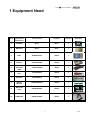
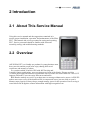
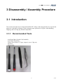
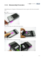
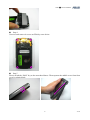
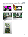
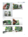
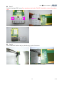
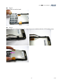
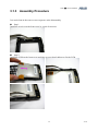
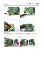
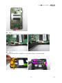
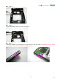
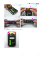
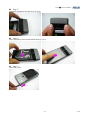
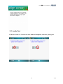
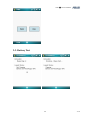
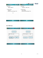
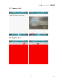
TSD ■ Service Manual ASUS P527 Service Manual (L1&L2) 1 V1.0 TSD ■ Service Manual 1 EQUIPMENT NEED............................................................................................................................. 3 2 INTRODUCTION ................................................................................................................................. 4 2.1 ABOUT THIS SERVICE MANUAL ......................................................................................................... 4 2.2 OVERVIEW ........................................................................................................................................... 4 2.3 PRODUCT SPECIFICATION ................................................................................................................... 5 3 DISASSEMBLY / ASSEMBLY PROCEDURE................................................................................... 6 3.1 INTRODUCTION .................................................................................................................................... 6 3.1.1 RECOMMENDED TOOLS ...................................................................................................................... 6 3.1.2 DISASSEMBLY PROCEDURE ................................................................................................................ 7 3.1.3 ASSEMBLY PROCEDURE ................................................................................................................... 15 3.2 EXPLODED DIAGRAM ........................................................................................................................ 22 4 MMI TESTING ................................................................................................................................... 23 2 V1.0 TSD ■ Service Manual 1 Equipment Need NO# Equipment Description ASUS Part# Supplier Quantity 1 Computer None None 1 2 SIM Card None None 1 3 P527 80A-S5G1003 ASUS 1 4 Battery 07G016043459 ASUS 1 5 USB download cable 14G000506200 ASUS 1 6 Screwdriver (T5) 16-T00362002 ASUS 1 7 Tweezers 16-000600014 ASUS 1 8 Plastic Wrench 13GV0400PZZZ ASUS 1 9 Micro SD Card 04G352800500 ASUS 1 10 ADAPTER 04G267013800 ASUS 1 3 Remarks V1.0 TSD ■ Service Manual 2 Introduction 2.1 About This Service Manual Using this service manual and the suggestions contained in it assures proper installation, operation, and maintenance of the PDA P527. This manual aids service personnel in testing and repairing P527. Service personnel should be familiar with electronic assembly, testing, and troubleshooting methods. 2.2 Overview ASUS PDA P527 is a friendly use product for young business man, heavy traveler and the people who enjoy sharing their travel experience and memory to others. As a product which is built-in GPS with full Travelog and Location Courier applications, users can share travel route with friends. Elegant and slim (15.4mm) ID design with numeric keypad and 8 hot keys make one touch come true. Also, P527 supports FM radio. Users can enjoy latest news and music. RSS Reader can help to receive up-to-date news or message without active access. ASUS ZIP makes users not to worry if the download file is compressed or not, just one click to open it. Memory auto clean let it always keeps enough memory space for the operation. Power saving is extra benefit. BCR digitizes contact information with high recognition rate. TSD ■ Service Manual 2.3 Product Specification Networking EDGE/GPRS/GSM 850/900/1800/1900 system EGPRS Class B, Multi-slot Class 10 Operating System Microsoft Windows Mobile 6 Professional CPU TI OMAP 850 (200MHz) Dimensions 113 x 58 x 15.4 mm, 125g Battery 1300 mAh Lithium-Ion Talk time 4-5 hour Standby time 150-200 hours Form Factor Bar type with numeric keypad Color Dark Gray Display 2.6“, 65K, TFT , 240 x 320 Connectivity WLAN 802.11 b+g / Bluetooth 2.0+EDR / FM / USB v1.1 Browsing HTTP and WAP 1.2.1/2.0 Messaging SMS/MMS/Email/MSN Memory 128 MB Flash + 64 MB SDRAM Expansion Slot Micro-SD (SDHC supports) GPS GPS (SiRF III Solution with internal antenna) JAVA J2ME Camera 2 Mega-Pixel (Auto focus) Audio MP3, WMA, and AAC Video MPEG4 / H.263 Playback and Recording Ringtone MIDI and MP3 PIM/Utilities Word (editor), Excel (editor), and Power Point (viewer) Advanced Travelog, FM radio, Bluetooth Presenter, Location courier Business Card Recognition, RSS reader, Meeting planner, Memory auto clean, GPS catcher, TMC(optional) 5 V1.0 TSD ■ Service Manual 3 Disassembly / Assembly Procedure 3.1 Introduction This section describes how to disassemble PDA P527. Many of the integrated devices used in this phone are vulnerable to damage. Ensure adequate static protection is in place when handling, shipping, and servicing any internal components. 3.1.1 Recommended Tools Anti-Static Mat (Ground Cord included) Anti-Static Wrist Strap Torque Screw Driver (T5 type, torque is set to 1.2kg-cm) Tweezers Plastic blade 6 V1.0 TSD ■ Service Manual 3.1.2 Disassembly Procedure The following set of diagrams will demonstrate the correct sequence and action to disassemble P527. Step 1 Take the stylus away from the PDA. Step 2 Remove the battery case and take the battery away. Step 3 Take off the antenna cover by plastic blade. 7 V1.0 TSD ■ Service Manual Step 4 Unscrew and remove 4 screws on PDA by screw driver. Step 5 Please switch the “Hold” key as the arrowhead shows. Then separate the middle cover from front cover by plastic blade. 8 V1.0 TSD ■ Service Manual Step 6 Remove the speaker by a pair of tweezers. Step 7 Remove the vibrator by a pair of tweezers. 9 V1.0 TSD ■ Service Manual Step 8 Release the antenna FPC by a pair of tweezers. Then tear off the antenna FPC from middle cover by hand. Step 9 Open the LCM connector by plastic blade and release the LCM FPC by a pair of tweezers. Step 10 Separate the main board from front cover. Pay attention to the hook at the bottom of the front cover. Main board should be released from it first. 10 V1.0 TSD ■ Service Manual Step11 Open the camera connector by plastic blade and remove it from main board by hand. Step12 Open the touchpad FPC connector and release the FPC by a pair of tweezers. 11 V1.0 TSD ■ Service Manual Step13 Take the touchpad FPC away. Pay attention to the hooks. The FPC should be released from them first. Step14 Take off the MIC rubber and joy stick key by a pair of tweezers. 12 V1.0 TSD ■ Service Manual Step15 Take off the keypad by hand. Step16 Remove the two top bezel rubbers by a pair of tweezers and then take the LCD module away. 13 V1.0 TSD ■ Service Manual Step17 Remove the receiver by a pair of tweezers. 14 V1.0 TSD ■ Service Manual 3.1.3 Assembly Procedure It is carried out in the exact reverse sequence as the disassembly. Step 1 Install the receiver on the front cover by a pair of tweezers. Step 2 Install the LCM on the front cover and place two top bezel rubbers to fix the LCM. 15 V1.0 TSD ■ Service Manual Step 3 Install the keypad and arrange the keypad properly in the front cover. Step 4 Install the joystick key and MIC rubber by a pair of tweezers. Step 5 Install the keypad FPC on main board and press gently to arrange it into the hooks. 16 V1.0 TSD ■ Service Manual Step 6 Connect the keypad FPC with main board by a pair of tweezers and close the connector by plastic blade. Step 7 Install the camera by hand and close its connector by plastic blade. Step 8 Install the main board on front cover and press gently to fix it into the hook. Please notice the hook on top of front cover. The main board should be inserted first and then arranged into the hook at bottom of front cover. 17 V1.0 TSD ■ Service Manual Step 9 Connect the LCM FPC by a pair of tweezers and close its connector by plastic blade. Step 10 Install the antenna FPC on middle cover and then arrange it by plastic blade. 18 V1.0 TSD ■ Service Manual Step 11 Install the vibrator by a pair of tweezers. Step 12 Then install the speaker by a pair of tweezers. Step 13 Install the middle cover and press four sides to lock it into the hooks. Pay attention to the “Hold” key, please switch it firstly as the arrowhead shows. 19 V1.0 TSD ■ Service Manual Step 14 Secure 4 screws on middle cover by screw driver. 20 V1.0 TSD ■ Service Manual Step 15 Install the antenna cover and press to fix it. Step 16 Place the battery back and install the battery cover. Step 17 Insert the stylus. 21 V1.0 TSD ■ Service Manual 3.2 Exploded Diagram 22 V1.0 TSD ■ Service Manual 4 MMI Testing 1. Download & Copy files to micro SD card. 2. Insert micro SD card. 23 V1.0 TSD ■ Service Manual 3. Please follow instructions as displayed. 3-1. Touch Panel Calibration Test 24 V1.0 TSD ■ Service Manual 3-2. Audio Test In this test, item 1 & 2 need to be done with the headphone, otherwise, just bypass. 25 V1.0 TSD ■ Service Manual 26 V1.0 TSD ■ Service Manual 27 V1.0 TSD ■ Service Manual 3-3. Battery Test 28 V1.0 TSD ■ Service Manual 3-4. FM Test 29 V1.0 TSD ■ Service Manual 3-5. Keypad Test 3-6. Bluetooth Test 30 V1.0 TSD ■ Service Manual 3-7. Camera Test 3-8. Display Test 31 V1.0 TSD ■ Service Manual 32 V1.0 TSD ■ Service Manual 33 V1.0 TSD ■ Service Manual 3-9. LED Test 3-10. Vibrator Test 34 V1.0 TSD ■ Service Manual 3-11. Reset Button Test 35 V1.0