1
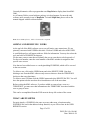
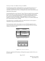
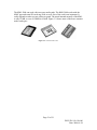
KANTRONICS
KML-5000 TraveLog
USER MANUAL
DWG ID: 181-0104-00
Date: 2006-01-24
Kantronics Co., Inc.
3115 West 6th Street, Suite A
Lawrence, Kansas 66049
Phone: 785-842-7745
Fax: 785-842-2031
Web: http://www.kantronics.com
DWG ID: 181-0104-00
Date: 2006-01-24
1
REVISIONS
Revisio
Date
n
0.1
2004-05-10
0.2
2005-09-09
Description
Preliminary
Revised with smaller CCA and packaging. Added installation
information
Page 3 of 21
DWG ID: 181-0104-00
Date: 2006-01-24
2
TABLE OF CONTENTS
1REVISIONS.......................................................................................................................3
2TABLE OF CONTENTS...................................................................................................4
3GENERAL INFORMATION............................................................................................5
3.2Sales/Inquiries.................................................................................................................5
4.2Technical Support...........................................................................................................5
5.2Miscellaneous.................................................................................................................5
6.2Disclaimer Notice...........................................................................................................5
7.2Kantronics Warranty Registration..................................................................................6
Date of Purchase: ___________________________..................................................................6
Dealer: _________________________________________________________________.......6
8.2Important Information.....................................................................................................7
9.2License Agreement.........................................................................................................7
3.1.1 License........................................................................................................................7
3.1.2 Term............................................................................................................................7
3.1.3 Object Code................................................................................................................7
3.1.4 Limited Warranty........................................................................................................7
3.1.5 General........................................................................................................................7
3.1.6 Other...........................................................................................................................8
10.2Limited Warranty..........................................................................................................8
3.1.7 WARRANTY.............................................................................................................8
3.1.8 REMEDY....................................................................................................................8
3.1.9 EXCLUSIVE REMEDY............................................................................................8
3.1.10 DISCLAIMER..........................................................................................................9
3.1.11 APPLICABLE PRODUCTS AND PERIODS.........................................................9
3.1.12 EXCLUSIONS..........................................................................................................9
3.1.13 REMEDY PROCEDURE.......................................................................................10
3.1.14 NON-ASSIGNMENT.............................................................................................10
3.1.15 OTHER RIGHTS....................................................................................................10
Return/Repair Procedures..................................................................................................10
3.1.16 Return Procedures...................................................................................................11
3.1.17 Service department contact information:................................................................11
Repair Service Charges......................................................................................................11
SPECIFICATION OF PRODUCT....................................................................................12
PRODUCT INFORMATION............................................................................................13
Model Identification...........................................................................................................13
What is the KML................................................................................................................14
How does it work...............................................................................................................14
What software can I use.....................................................................................................14
Adding and Removing Users.............................................................................................15
What are Pushpins..............................................................................................................15
What is a Territory.............................................................................................................16
Importing GPS data............................................................................................................16
What is the ACK file..........................................................................................................16
Page 4 of 21
DWG ID: 181-0104-00
Date: 2006-01-24
Working with GPS data.....................................................................................................17
Generating User reports.....................................................................................................17
Hardware Installation.........................................................................................................18
LED Indicators...................................................................................................................20
Page 5 of 21
DWG ID: 181-0104-00
Date: 2006-01-24
3
GENERAL INFORMATION
3.2 Sales/Inquiries
Phone:
Fax:
E-mail:
Web site:
785-842-7745 (8 AM to 5 PM, Central Time, Monday through Friday)
785-842-2031
[email protected]
http://www.kantronics.com
4.2 Technical Support
Phone:
Fax:
E-mail:
785-842-4476 (8 AM to Noon and 1 PM to 5 PM, Central Time, Monday
through Friday)
785-842-2031
[email protected]
5.2 Miscellaneous
The Kantronics TraveLog is manufactured in the U.S.A.
All brands and product names are trademarks of their respective companies.
6.2 Disclaimer Notice
We have attempted to make this manual technically and typographically correct as of the
date of the current issue. Production changes to the TraveLog may add changes to the
manual at a later date.
Send comments or suggest corrections to Kantronics Co., Inc., 1202 E. 23rd Street, Suite
A, Lawrence, KS 66046, or e-mail [email protected].
Information in this document is subject to change without notice.
Contents of this publication or the firmware/software within the TraveLog may not be
reproduced in any form without the written permission of the copyright owner.
Published in the United States of America.
Page 6 of 21
DWG ID: 181-0104-00
Date: 2006-01-24
7.2 Kantronics Warranty Registration
(Note: Print this page, fill out the form, and mail in.)
Please take the time to fill out a copy of the warranty registration form and mail it to
Kantronics, including a copy of your sales receipt, to register your purchase. Kantronics
must receive warranty registration within 10 days of purchase of the Kantronics
TraveLog to be valid. Both must be on file at Kantronics in order for you to receive
warranty service. Refer to the warranty policy in this manual for further information.
Mail form and sales receipt to:
Kantronics
1202 E 23rd Street, Suite A
Lawrence, KS 66046
Warranty Registration
Entity Name: ____________________________________________________________
Address: _______________________________________________________________
City: __________________________________________________________________
State: _______________________________ Zip/Postal Code: ____________________
Country: _______________________________________________________________
Contact Person’s Name: ___________________________________________________
Telephone Nr: ___________________________________________________________
E-mail: _________________________________________________________________
Product: TraveLog
Serial Nr: _________________________________
Date of Purchase: ___________________________
Dealer:
________________________________________________________________
_
Page 7 of 21
DWG ID: 181-0104-00
Date: 2006-01-24
8.2 Important Information
READ THIS SECTION BEFORE INSTALLING THIS KANTRONICS PRODUCT
This product contains SOFTWARE in FLASH Memory, which is protected by both
United States copyright law and international treaty provisions.
If you install or use this product, you are bound by the terms of the SOFTWARE license
shown below. If you do not wish to be bound by such license, return the (unused)
complete product package to your supplier for refund. The supplier may deduct
restocking/re-packaging costs.
9.2 License Agreement
3.1.1
License
In consideration of payment of the License Fee, which is included in the price of the
product, the Licensor Kantronics Company, Inc. (Kantronics) grants (you) a nonexclusive right to use the SOFTWARE and associated documentation. No ownership
rights to the SOFTWARE or its Documentation are transferred from Kantronics to you.
3.1.2
Term
This License Agreement is effective until terminated. You may terminate this Agreement
by returning or destroying the unit and destroying the documentation. You may not rent
or lease the SOFTWARE, but you may transfer the SOFTWARE and accompanying
written materials on a permanent basis provided you retain no copies and the recipient
agrees to the terms of this Agreement. Kantronics may terminate this Agreement without
notice if you violate any terms or conditions of the agreement. In the event of termination
of the Agreement, provisions relating to Kantronics' disclaimers of warranties, limitation
of liability, remedies, or damages and Kantronics' proprietary rights shall survive.
3.1.3
Object Code
The SOFTWARE is delivered in object code only. You shall not reverse compile or
otherwise reverse engineer the SOFTWARE.
3.1.4
Limited Warranty
This product is covered by the standard Kantronics Company, Inc. Limited Warranty.
3.1.5
General
This License Agreement constitutes the complete Agreement between you and
Kantronics. The SOFTWARE and/or Documentation may not be exported or re-exported
Page 8 of 21
DWG ID: 181-0104-00
Date: 2006-01-24
in violation of any export laws or regulations of the United States of America or any
other applicable jurisdiction. This Agreement shall be governed by and interpreted under
the laws of the State of Kansas, United States of America. Use, duplication, or disclosure
by the Government of the United States is subject to restrictions as set forth in
subparagraph (c)(1)(ii) of the Rights in Technical Data and Computer SOFTWARE
clause of DFARS 252.227-7013. Kantronics may in its sole discretion, provide you with
upgrades of the SOFTWARE and/or Documentation if you have provided Kantronics
your completed Warranty registration with a copy of your receipt showing the amount
you paid.
3.1.6
Other
LICENSEE ACKNOWLEDGES HAVING READ AND UNDERSTOOD THIS
AGREEMENT AND AGREES TO BE BOUND BY ITS TERMS. LICENSEE
FURTHER AGREES THAT THIS AGREEMENT IS THE COMPLETE AND
EXCLUSIVE STATEMENT OF THE AGREEMENT BETWEEN LICENSEE AND
LICENSOR AND SUPERSEDES ANY PROPOSAL OR PRIOR AGREEMENT, ORAL
OR WRITTEN, AND ANY OTHER COMMUNICATIONS RELATING TO THE
SUBJECT MATTER OF THIS AGREEMENT.
10.2Limited Warranty
KANTRONICS COMPANY, INC.
Effective 2003-09-01
To receive notice of future updates, or free copy of this manual, please go to
http://www.kantronics.com.
NOTE: Return of the Warranty Registration and proof of purchase is a pre-condition to
warranty coverage.
3.1.7
WARRANTY
Kantronics Co., Inc. ("Kantronics") warrants to the first consumer purchaser ("you"), for
the Applicable Warranty Period (as described below), that the Applicable Product (as
described below) will be free from defects in material and workmanship.
3.1.8
REMEDY
Kantronics agrees that, for any Applicable Product found by Kantronics to be in violation
of the warranty within the Applicable Warranty Period, it will, at its option, repair or
replace the defective Applicable Product at no charge to you, excluding in-bound
shipping charges.
3.1.9
EXCLUSIVE REMEDY
Page 9 of 21
DWG ID: 181-0104-00
Date: 2006-01-24
Repair or replacement of the Applicable Product, as provided herein, is the sole remedy
available to you against Kantronics, and in no event will Kantronics be responsible for
any other liability or damages or for incidental, special, or consequential damages,
regardless of whether purported liability is predicated upon negligence, strict tort,
contract, or other products liability theory and whether or not Kantronics is warned about
the possibility of such liability or damages. SOME STATES DO NOT ALLOW THE
EXCLUSION OR LIMITATION OF INCIDENTAL OR CONSEQUENTIAL
DAMAGES, SO THE ABOVE LIMITATION OR EXCLUSION MAY NOT APPLY
TO YOU.
3.1.10 DISCLAIMER
This Limited Warranty is in lieu of all other warranties expressed or implied and no
representative or person is authorized to assume for Kantronics any other liability in
connection with the sale of its products. KANTRONICS SPECIFICALLY DISCLAIMS
THE IMPLIED WARRANTY OF MERCHANTABILITY AND IMPLIED
WARRANTY OF FITNESS FOR A PARTICULAR PURPOSE FOR ANY
APPLICABLE PRODUCT. IF, HOWEVER, YOU ARE A CONSUMER WITHIN THE
MEANING OF 15 U.S.C. 2301(3), THE ABOVE DISCLAIMER OF IMPLIED
WARRANTIES IS EFFECTIVE ONLY FOR PERIODS OUTSIDE THE APPLICABLE
WARRANTY PERIOD. SOME STATES DO NOT ALLOW LIMITATIONS ON HOW
LONG AN IMPLIED WARRANTY LASTS, SO THE ABOVE LIMITATION MAY
NOT APPLY TO YOU.
3.1.11 APPLICABLE PRODUCTS AND PERIODS
Kantronics products are of two types: (1) hardware units and (2) firmware and software
for operation of these units, whether incorporated into the units themselves or separate
from the units as adjuncts or accessories to the units. Hardware units and the media
containing firmware, software, and documentation are sold to the consumer purchaser
and become property of the purchaser. Firmware and software are licensed for use by the
consumer purchaser in return for a fee included in the purchase price of the units and do
not become the property of the consumer. The product to which this warranty applies
(herein "Applicable Products") and the period during which the warranty shall apply
(herein, "Applicable Warranty Period") are as follows:
Applicable Product: KML-5000 TraveLog.
Applicable Warranty Period: Two (2) years from date of purchase.
3.1.12 EXCLUSIONS
This Limited Warranty does not apply to the cosmetic appearance of the Applicable
Product; to broken or cracked cabinets; to any accessory not supplied by Kantronics
which is used with the Applicable Product; to any product that has been subject to
misuse, abuse, or over-voltage; to any product that has been modified by non-Kantronics
personnel unless specifically authorized in writing by Kantronics; or to any product
Page 10 of 21
DWG ID: 181-0104-00
Date: 2006-01-24
damaged or impaired by shipping (whether or not caused by poor packaging), neglect,
accident, wiring not installed by Kantronics, improper parameter settings which are
cleared by performing a hard reset, or use in violation of instructions furnished by
Kantronics or of generally accepted industry practice. Kantronics does not warrant that
the functions contained in any software will meet your requirements or achieve your
intended results; or that operation of any software will be uninterrupted or error-free or
without effect upon other software used with it. Responsibility for the selection of the
hardware and software program to achieve your intended results rests with you.
3.1.13 REMEDY PROCEDURE
Should you need to make a warranty claim, first contact the dealer from whom you
purchased the product. If the dealer is unable to assist you, contact Kantronics Co., Inc.:
• By mail at 1202 East 23rd Street, Suite A, Lawrence, Kansas 66046 USA
• By fax at 785-842-2031
• By phone at our Customer Support number 785-842-4476 (Hours: 8 AM to Noon and
1 PM to 5 PM, Central Time)
• Or by e-mail at [email protected].
Contact us prior to returning an Applicable Product to receive a Return Authorization
Number. (As a practical matter, problems can often be solved in such a manner without
the product having to be returned to Kantronics for repair or replacement.) Return of any
Applicable Product for the enforcement of rights under this Limited Warranty shall be at
your expense. Any product returned for warranty service, which Kantronics determines to
be without defect or not covered by this Limited Warranty, shall be subject to a minimum
labor charge and the product will be returned to you at your sole expense. Please note, no
warranty service will be provided until Kantronics has been furnished with your
Warranty Registration and copy of proof of purchase establishing purchase date.
3.1.14 NON-ASSIGNMENT
This Limited Warranty is not assignable by you. Any attempt to assign or transfer any of
the rights, duties, or obligations hereof is void.
3.1.15 OTHER RIGHTS
This Limited Warranty gives you specific legal rights and you may also have other rights,
which vary from jurisdiction to jurisdiction.
Return/Repair Procedures
Important: Our repair statistics show that a large percentage of units returned for
service, do not, in fact, require any service. Therefore, we advise you to please doublecheck the following list of common, user-solvable, sources of difficulty before contacting
Kantronics about returning your unit for service. An RMA (Return Merchandise
Authorization) number must be requested and received, and included with the unit
Page 11 of 21
DWG ID: 181-0104-00
Date: 2006-01-24
returned for repair. If a unit is received without an RMA number, the shipment will be
denied.
3.1.16 Return Procedures
When calling the service department, have the following information available:
•
The unit name and serial number (the serial number is found on the bottom of the
unit)
3.1.17 Service department contact information:
Kantronics Co., Inc.
1202 E. 23rd Street, Suite A
Lawrence, KS 66046
The Service Department telephone hours are 8 AM to Noon and 1 PM to 5 PM
Central Time, Monday through Friday. Telephone access to the service department
is not available outside the stated hours.
Phone:
Fax:
E-mail address:
Web site:
785-842-4476 (8 AM to Noon and 1 PM to 5 PM, central time)
785-842-2031
[email protected]
http://www.kantronics.com
When writing, faxing, or sending e-mail to Kantronics, include a clear description of the
problem and unit name.
Be sure to include a return fax number, mailing address, and/or e-mail address.
Returns direct to the factory for refund or exchange, are strictly regulated. The sales
department must approve any return for refund or exchange.
If the unit was recently purchased from one of our authorized dealers, contact that dealer
first.
Repair Service Charges
Consult the limited warranty policy in this manual for the service provisions offered by
Kantronics at no charge. This warranty is considered to be in force only when the
customer has submitted a completed warranty registration within ten days (10 d) of
purchase, and when the stipulations of the warranty have been met.
Violations of warranty clauses will automatically void the warranty, and cost of service
or repairs will be charged to the owner. Service outside the warranty period will be
charged at the cost of parts, labor, and return shipping, at the time of the repair or service.
Page 12 of 21
DWG ID: 181-0104-00
Date: 2006-01-24
Units sent in for service or repair, without prior Return Authorization, will be subject to
the minimum charge for labor plus cost of return shipping and handling.
Repair or DAMAGE to a unit, whether accidental or otherwise, is not covered by any
warranty provided by Kantronics, in which case, normal repair charges will apply.
Contact the Service Department at:
• 785-842-4476 (hours: 8 AM to Noon and 1 PM to 5 PM Central Time)
• Or e-mail to [email protected]
to obtain a Return Authorization number.
Repaired units will be returned via FedEx (or UPS) C.O.D., if other payment
arrangements have not already been arranged. C.O.D. charges can be avoided by
providing payment information (VISA, MasterCard, or Discover) either at the time of the
return authorization request, or included with the unit, when it is sent to be repaired.
PRODUCT INFORMATION
The TraveLog equipment uses a GPS receiver, microcontroller unit, Flash EEPROM, and
peripheral components to log GPS location and time data and then download it to an
MMC.
Note: This equipment is only for installation in a transportation vehicle including a
motor vehicle.
Model Identification
Model
KML-5000 TraveLog
Kantronics P/N
001-0020-01
SPECIFICATION OF PRODUCT
Supply Voltage
+12 V dc nominal (vehicle applications)
Page 13 of 21
DWG ID: 181-0104-00
Date: 2006-01-24
Operating Supply Current @ 13.8 V dc
Supply Current in sleep mode (ignition off)
Power Connector
Operating Temperature
Humidity, maximum
Dimensions w/o Protrusions
Weight/Mass
100 mA maximum
1.60 mA maximum
RIA Connect 3-pole Header
-30 to +60 °C
95 % non-condensing
0.904” H X 1.690” W X 2.625” D
TBD ounces (TBD g)
WHAT IS THE KML 5000
The KML-5000 Passive Tracker provides recording of vehicle or equipment location for
later retrieval.
Kantronics' KML-5000 Passive Tracker includes a GPS receiver and a data-logger. Once
installed in a vehicle, it can record up to 36 eight-hour days of GPS data (location,
velocity, time) in a non-volatile internal memory. At your convenience, the captured
history can be transferred from the internal memory to a removable memory card for
transport to a personal computer for viewing and analysis.
This product is optimized for uses such as logging the travel of a fleet of vehicles (e.g.,
used by pharmacy reps, account reps, bus drivers). Important features include low cost
(since no cell phone or radio is used), convenience, and the ability to capture accurate,
complete location data.
HOW DOES IT WORK?
The KML 5000 simply stated is a smart file cabinet. When the vehicle ignition is on, the
KML 5000 locates its position with GPS and then logs that position every couple seconds
to a file stored internally.
When you need to know where a vehicle has been you can download the stored GPS
information to a media card and then load it into a PC and view a map with generated
data from the media card to give a graphic representation of locations, direction, speeds,
etc.
This can be accomplished with a single user or a whole fleet of vehicles and can even be
broken up into territories.
WHAT SOFTWARE CAN I USE?
Page 14 of 21
DWG ID: 181-0104-00
Date: 2006-01-24
Currently Kantronics offers a program that uses Map Point to display data from KML
5000.
As of January 2006 a second software package is in development. For now the only
software suite currently in use is MapPoint. To install MapPoint, please refer to the
manual shipped with the software bundle.
Note: To use KML software, .NET 1.1 Framework is required.
ADDING AND REMOVING USERS.
At the top left of the KML software screen you will notice some menu items. We are
primarily concerned with USERS at this time. Click on USERS and select ADD USER.
A small dialogue box will appear with two fields for information. You may also select the
style and color of PUSHPIN for that user.
For the name, enter a name that will identify the user or asset that is to be kept track of.
For the serial number, enter the serial number of the KML unit that is assigned to that
specific user or asset.
Now that we have added a user we can begin adding PUSHPINS, which will be covered
in the next section.
To delete a user, click on the USERS menu and select DELETE USER. Note that
deleting a user from the KML software only removes that user from the TERRITORY
but leaves that users data intact.
To delete a users GPS data click the USERS menu and select DELETE DATES. You will
have the option to delete user data for selected dates or all of the users data.
Before exiting the KML software, if you have added or removed any users to a
TERRITORY, you must save that information to the TERRITORY associated with the
user or group of users.
This can be accomplished from the FILE menu in the top left section of the screen.
WHAT ARE PUSHPINS
Put quite simply, a PUSHPIN is the same as on any other map, a location marker.
PUSHPINS are used in the address lookup function, as you will see later in the USER
REPORTS section.
Page 15 of 21
DWG ID: 181-0104-00
Date: 2006-01-24
When performing address lookup, MAP POINT will attempt to find an address for
starting and stopping locations based on GPS data. This, however, is not an exact science.
Some areas do not have an actual address, such as a parking lot. So MAP POINT will
first look for any nearby PUSHPINS and use that information for the location data.
PUSHPINS should be placed in locations where vehicles are expected to stop or visit
frequently such as schools, doctor’s offices, garage, etc.
To add a PUSHPIN to a user, click on the USERS menu and select ADD PUSHPIN. A
dialog box will appear and require a location to find. Once the location has been found
click OK. As stated earlier, this is not always exact so you may need to move the
PUSHPIN a little. If this is the case, simply drag the PUSHPIN to the location where it
should actually be located.
You may edit the information contained in a PUSHPIN by double clicking on it. The
name of the PUSHPIN can be changed to something more memorable such as home,
library, offices, etc.
To delete a PUSHPIN from a user, click on it and press delete on your keyboard.
WHAT IS A TERRITORY
A TERRITORY is collection of USERS and PUSHPINS. Once you have added users and
placed pushpins, click on the FILE menu and select SAVE TERRITORY. When opening
the KML software to work with new or existing GPS data, you must load the
TERRITORY containing the user information you wish to work with or add to.
IMPORTING GPS DATA
We are now ready to import user GPS data. To do this, select a user from the dropdown
list of users in the KML software. Next select the USERS menu and then select IMPORT
GPS. Navigate to the directory and or file where user GPS data is stored. Select that users
GPS data and click OK.
Users “.gps “ files will have the serial number of the unit they come from embedded
within the file name. This serial number should match that of the user. User GPS files are
encrypted and have the serial numbers embedded in them also. Trying to open GPS data
with non-matching serial numbers or if the file appears to have been tampered with will
generate an error.
If user and file serial numbers match, the KML software will begin processing the GPS
data. Be patient, this may take a few minutes based on file size and computer speed.
WHAT IS THE “.ACK “ FILE AND WHAT IS ITS PURPOSE.
Page 16 of 21
DWG ID: 181-0104-00
Date: 2006-01-24
After GPS data is processed, a new encrypted file is generated. This is the “ACK” file.
This file will be saved to the same location as the original GPS file. For example, if the
user GPS data is stored in “C:\USERS\GPS” then the ACK file will be generated there as
well.
When the KML 5000 is writing data to a media card it will check for the existence of an
ACK file. The ACK file contains the most recent dates and times collected by the KML
5000.
If a valid ACK file exists on the media card the KML 5000 will only write data that is
more recent than what data is contained in the existing ACK file.
NOTE: If a valid ACK file is not found on the media card, all GPS data will be written
to the media card.
WORKING WITH GPS DATA
Now that you have imported the user GPS data lets figure out what it means.
After the ACK file is written the KML software will select the most recent date for which
there is data for the selected user and plot that data to the screen. It is possible to display
more than one user and or date at a time, however in the case of a single user the GPS
data is color coded for speed indication. If more than one user is displayed GPS data is
color coded by user only.
To display more than one user or date click on the USER or DATE drop down menus
and using the control (Ctrl) or shift (Shift) keys with the left mouse button to select a
range of users or dates. Keep in mind when working with multiple users or dates, it may
take some time for your system to display the data.
You may also move or delete line segments with the mouse to see the layered data. This
affects only the display and not the actual GPS data.
GENERATING USER REPORTS
There are several reports that can be generated from the imported GPS data.
The first type is a “Trip Report”.
Click on the USER menu and select REPORT. As shown in figure 5-3 data is displayed
in a spreadsheet format. Starting and ending times are displayed along with location,
distance, average speed, and maximum speed. Right click a location to edit the location
if it is not displayed correctly such as a blank entry or wrong address.
Double clicking on an entry will cause a zoom to that location on the map.
Page 17 of 21
DWG ID: 181-0104-00
Date: 2006-01-24
A bold line indicates that the KML 5000 has had a power-up reset. That means that
power to the KML has been disconnected and then reconnected again . This does not
erase stored GPS data.
This event is shown as an asterisk (*) in column 1 of the printed report as in figure 5-4.
Italic lines indicate “random position fixes” which occur about every 60 minutes while
the ignition is off.
This event is shown as a period (.) in column 1 of the printed report.
A red line indicates a GPS antenna fault, such as an unplugged cable.
This event is shown as an exclamation (!) in column 1 of the printed report.
In addition to printing the entire report, whole sections or even single lines can be
printed.
To print a section or single line of the report. Use the Control (Ctrl) and Shift (Shift)
keys on the keyboard with the left mouse button to select the line or lines to be printed.
A Speed report can also be generated.
HARDWARE INSTALLATION
Vehicle Installation Requirements
The power requirements for the KML 5000 are fairly simple. As with any electric device
there is power and ground. However the KML has a second “power” input. This second
input is the ignition sense.
This line is used so that the stored GPS data will reflect when the vehicle is started and
stopped as well as logging travel and destinations.
Installation of the KML is a fairly simple process. First secure the KML in your vehicle
somewhere out of the operators way.
Build the power connection using #22 or #24 AWG wire and the supplied power
connector.
(Please refer to figure 3-1 and 3-2)
The recommended wire colors are:
Ground – Black
+12 V dc constant – Red
+12 V dc sense – Yellow
Page 18 of 21
DWG ID: 181-0104-00
Date: 2006-01-24
You may, of course, use whatever colors you would like.
Next hook up the ground to a solid ground source. Any ground will work, however, I
recommend attaching to the vehicle chassis just under the driver side door strip or
somewhere on the floor board. This is a solid ground to the vehicle chassis and causes no
obstruction for the operator.
Now hookup the power to an “always on” source. There are a couple of ways to go about
this. One is to run a wire all the way to the vehicle battery. While this will get the job
done, it is time consuming and problematic. So I would recommend finding a source in
the vehicle fuse panel and securing it with the appropriate wire end. You can use a
multimeter or fuse tester to find what terminals are “always-on” and what terminals only
have current when the vehicle is running.
The ignition sense wire should be routed to the vehicle fuse box as well, except to a
feature that is only powered when the key is on.
You may of course run the wires to where ever you can find the appropriate power
sources. The fuse box is recommended due to its close proximity to the most common
equipment mounting locations.
Termina
l
Connection
1
Vehicle Ground
2
+12 V dc (ignition
sense)
3
+12 V dc constant
Figure 3-1: Power plug pin assignment
Figure 3-2: Power connector view from rear.
With power applied the LED indicators will begin their sequence which I will cover in
the next section.
Page 19 of 21
DWG ID: 181-0104-00
Date: 2006-01-24
Make sure the GPS antenna is hooked up and mounted somewhere either in or outside the
vehicle with a clear view of the sky.
The GPS antenna is magnetic and will hold to the body of the vehicle. It is recommended
that this antenna be mounted on the roof of the vehicle. However, mounting the antenna
on the dash board inside the vehicle is another option that may work just as well.
You must use the antenna provided to receive GPS data. Another type of antenna, such as
a “whip”, wired up to the GPS antenna will receive very little if any satallite signals.
There are 2 reasons for this:
1. The actual “node” that is the antenna has a small preamp built into it
2. GPS signals are “circularly polarized” and as such the antenna is built specifically
to accomidate this type of polarization.
LED Indicators
There are 3 LED indicators on the KML 5000. Yellow, Green, and Red.
When the KML is powered on from a “cold boot” state, the yellow indicator will flash in
5 second intervals (5 on, 5 off). When a GPS signal “lock” is aquired the yellow LED
will cease activity and the green LED will flash briefly every 32 seconds.
Though this seems like long intervals, this sequence indicates normal operation.
NOTE: Be patient it can take up to 5 minutes to aquire a satillite signal.
The red LED is only active when the media card is inserted. DO NOT remove the media
card while the red LED is steadily active. The red LED will be steadily active while the
media card is inserted. When data is being written to the media card, both red and green
LED's will flash.
Once all data has been written successfully, all LED's will blink rapidly. It is safe to
remove the media card while all LED's are actively flashing.
If any errors occur in the data transfer only the red LED will blink. You may remove the
media card while the red LED is actively blinking.
Working with Media cards
Page 20 of 21
DWG ID: 181-0104-00
Date: 2006-01-24
The KML 5000 can work with two types media cards. The KML 5000 works with the
MMC type and some SD cards may work as well. Size of the card is not important. It
really depends on what you are willing to spend. The actual internal memory of the KML
is only 32 MB, so even a 128MB is overkill. Figure 3-3 shows some of the more common
media card types.
Figure 3-3: common media cards
Page 21 of 21
DWG ID: 181-0104-00
Date: 2006-01-24