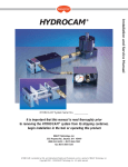
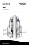
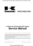
1
For Kawasaki Discount Parts Call 606-678-9623 or 606-561-4983
KHD600A
KHS750A
Hedge Trimmer (Chapter of cutter blades main body)
Service Manual
All rights reserved. No parts of this publication may be reproduced, stored in a retrieval system, or transmitted in any
form or by any means, electronic mechanical photocopying, recording or otherwise, without the prior written permission of
Quality Assurance Department/Consumer Products & Machinery Group/Kawasaki Heavy Industries, Ltd., Japan.
No liability can be accepted for any inaccuracies or omissions in this publication, although every possible care has been
taken to make it as complete and accurate as possible.
The right is reserved to make changes at any time without prior notice and without incurring an obligation to make such
changes to products manufactured previously.
All information contained in this publication is based on the latest product information available at the time of publication.
Illustrations and photographs in this publication are intended for reference use only and may not depict actual model
component parts.
© Kawasaki Heavy Industries. Ltd. 1999
www.mymowerparts.com
First Edition:Jan. 29, 1999 (K)
For Kawasaki Discount Parts Call 606-678-9623 or 606-561-4983
LIST OF ABBREVIATIONS
A
ampere(s)
lb
pounds(s)
ABDC
AC
ATDC
BBDC
BDC
BTDC
C
DC
F
F
ft
g
h
L
after bottom dead center
alternating current
after top dead center
before bottom dead center
bottom dead center
before top dead center
degree(s) Celsius
direct current
farad(s)
degree(s) Fahrenheit
foot, feet
gram(s)
hour(s)
liter(s)
m
min
N
Pa
PS
psi
r
rpm
TDC
TIR
V
W
meter(s)
minute(s)
newton(s)
pascal(s)
horsepower
pound(s) per square inch
revolution
revolution(s) per minute
top dead center
total indicator reading
volt(s)
watt(s)
ohm(s)
Read OWNER’S MANUAL before operating.
www.mymowerparts.com
For Kawasaki Discount Parts Call 606-678-9623 or 606-561-4983
EMISSION CONTROL INFORMATION
To protect the environment in which we all live, Kawasaki has incorporated exhaust emission control systems (EM) in
compliance with applicable regulations of the United States Environmental Protection Agency and California Air Resources
Board.
1. Exhaust Emission Control System
The exhaust emission control system applied to this engine consists of a carburetor and an ignition
system having optimum ignition timing characteristics.
The carburetor has been calibrated to provide lean air/fuel mixture characteristics and optimum fuel
economy with a suitable air cleaner and exhaust system.
TAMPERING WITH NOISE CONTROL SYSTEM PROHIBITED
Federal law and California State law prohibits the following acts or the causing thereof: (1) the removal or rendering
inoperative by any person other than for purposes of maintenance, repair, or replacement, of any device or element of
design incorporated into any new engine for the purpose of emission control prior to its sale or deliverly to the ultimate
purchaser or while it is in use, or (2) the use of the engine after such device or element of design has been removed or
rendered inoperative by any person.
Among those acts presumed to consituite tampering are the acts listed below:
Do not tamper with the original emission related part:
•
•
•
•
•
Carburetor and internal parts
Spark plugs
Magneto or electronic ignition system
Fuel filter
Air cleaner elements
www.mymowerparts.com
For Kawasaki Discount Parts Call 606-678-9623 or 606-561-4983
Foreword
This KHD600A/KHS750A Service Manual is designed
to be used in conjunction with the TF22 2–stroke air
cooled gasoline engine Service Manual (P/N 99924–
2503–02). The maintenance and repair procedures described in this manual are only those that are unique
to the body of the KHD600A/KHS750A Hedge Trimmer.
Most service operations for this model remain identical to
those described in the engine Service Manual. Complete
and proper servicing of the KHD600A/KHS750A blower
therefore requires both this manual and the engine Service Manual.
The engine Service Manual and this manual are designed primarily for use by trained mechanics in a properly
equipped shop. However, they contain enough detail and
basic information to make them useful to the owner who
desires to perform his own basic maintenance and repair
work. A basic knowledge of mechanics, the proper use
of tools, and workshop procedures must be understood
in order to carry out maintenance and repair satisfactorily. Whenever the owner has insufficient experience or
doubts his ability to do the work, all adjustments, maintenance, and repair should be carried out only by qualified
mechanics.
In order to perform the work efficiently and to avoid
costly mistakes, read the text, thoroughly familiarize
yourself with the procedures before starting work, and
then do the work carefully in a clean area. Whenever
special tools or equipment are specified, do not use
makeshift tools or equipment. Precision measurements
can only be made if the proper instruments are used,
and the use of substitute tools may adversely affect safe
operation.
For the duration of the warranty period, we recommend that all repairs and scheduled maintenance be
performed in accordance with this service manual. Any
owner maintenance or repair procedure not performed in
accordance with this manual may void the warranty.
To get the longest life out of your equipment:
Follow the Periodic Maintenance Chart in the Service
Manual.
Be alert for problems and non-scheduled maintenance.
Use proper tools and genuine Kawasaki engine parts.
Special tools, gauges, and testers that are necessary
when servicing Kawasaki vehicles are introduced by
the Special Tool Catalog or Manual. Genuine parts
provided as spare parts are listed in the Parts Catalog.
•
•
•
the procedures in this manual carefully. Don’t
• Follow
take shortcuts.
to keep complete records of maintenance
• Remember
and repair with dates and any new parts installed.
How to Use This Manual
All information for a particular system from adjustment
through disassembly and inspection is located in a single
chapter.
The Quick Reference Guide shows you all of the
product’s work and assists in locating their chapters.
Each chapter in turn has its own comprehensive Table
of Contents.
The Periodic Maintenance Chart is located in the
General Information chapter. The chart gives a time
schedule for required maintenance operations.
Whenever you see these WARNING and CAUTION
symbols, heed their instructions! Always follow safe
operating and maintenance practices.
This warning symbol identifies special instructions or procedures which, if not correctly followed, could result in personal injury, or loss of
life.
CAUTION
This caution symbol identifies special instructions or procedures which, if not strictly observed, could result in damage to or destruction
of equipment.
This manual contains four more symbols (in addition to
WARNING and CAUTION) which will help you distinguish
different types of information.
NOTE
This note symbol indicates points of particular interest for more efficient and convenient operation.
a procedural step or work to be done.
• Indicates
Indicates a procedural sub-step or how to do the work
of the procedural step it follows. It also precedes the
text of a NOTE.
Indicates a conditional step or what action to take based
on the results of the test or inspection in the procedural
step or sub-step it follows.
www.mymowerparts.com
For Kawasaki Discount Parts Call 606-678-9623 or 606-561-4983
GENERAL INFORMATION 1-1
General Information
Table of Contents
Before Servicing.................................................................................................................................................................1-2
Model Identification ............................................................................................................................................................ 1-4
General Specifications ....................................................................................................................................................... 1-6
Periodic Maintenance Chrat...............................................................................................................................................1-7
Tightening Torque...............................................................................................................................................................1-8
Special Tools, Sealant........................................................................................................................................................1-9
Sharpening Cutter Edges.................................................................................................................................................1-10
www.mymowerparts.com
1
For Kawasaki Discount Parts Call 606-678-9623 or 606-561-4983
1-2 GENERAL INFORMATION
Before Servicing
Before starting to service the engine, carefully read the applicable section to eliminate unnecessary work. Photographs,
diagrams, notes, cautions, warnings, and detailed descriptions have been included wherever necessary. Nevertheless,
even a detailed account has limitations, a certain amount of basic knowledge is required for successful work.
Especially note the following:
(1) Dirt
Before removal and disassembly, clean the engine. Any dirt entering the engine, carburetor, or other parts, will
work as an abrasive and shorten the life of engine. For the same reason, before installing a new part, clean off any
dust or metal filings.
(2) Tightening Sequence
Generally, when installing a part with several bolts, nuts, or screws, start them all in their holes and tighten them to
a snug fit. Then tighten them evenly, in a staggered sequence. This is to avoid distortion of the part and/or causing
gas or oil leakage. Conversely, when loosening the bolts, nuts, or screws, first loosen all of them by about a quarter
of a turn and then remove them. Where there is a tightening sequence indication in this Service Manual, the bolts,
nuts, or screws must be tightened in the order and method indicated.
(3) Torque
When torque values are given in this Service Manual, use them. Either too little or too much torque may lead to
serious damage. Use a good quality, reliable torque wrench.
(4) Force
Common sense should dictate how much force is necessary in assembly and disassembly. If a part seems especially
difficult to remove or install, stop and examine what may be causing the problem. Whenever tapping is necessary, tap
lightly using a wooden or plastic-faced mallet. Use an impact driver for screws(particularly for the removal of screws
held by a locking agent) in order to avoid damaging the heads.
(5) Edges
Watch for sharp edges, especially during major engine disassembly and assembly. Protect your hands with gloves
or a piece of thick cloth when lifting the engine or turning it over.
(6) High-Flash Point Solvent
A high-flash point solvent is recommended to reduce fire danger. A commercial solvent commonly available in North
America is Standard solvent (generic name). Always follow manufacturer and container directions regarding the use
of any solvent.
(7) Gasket, O-Ring
Do not reuse a gasket or O-ring once it has been in service. The mating surfaces around the gasket should be
free of foreign material and perfectly smooth to avoid oil or compression leaks.
(8) Liquid Gasket, Non-Permanent Locking Agent
Follow manufacturer’s directions for cleaning and preparing surfaces where these compounds will be used. Apply
sparingly. Excessive amounts may block engine oil passages and cause serious damage. An example of a nonpermanent locking agent commonly available in North America is Loctite Lock’n Seal (Blue).
(9) Press
A part installed using a press or driver, such as a journal, should first be coated with oil on its outer or inner
circumference so that it will go into place smoothly.
(10) Ball Bearing
When installing a ball bearing, the bearing race which is affected by friction should be pushed by a suitable driver.
This prevents severe stress on the balls and races, and prevents races and balls from being dented. Press a ball
bearing until it stops at the stop in the hole or on the shaft.
(11) Oil Seal, Grease Seal
Replace any oil or grease seals that were removed with new ones, as removal generally damages seals.
When pressing in a seal which has manufacturer’s marks, press it in with the marks facing out. Seals should be
pressed into place using a suitable driver, which contacts evenly with the side of seal, until the face of the seal is even
with the end of the hole.
(12) Seal Guide
A seal guide is required for certain oil or grease seals during installation to avoid damage to the seal lips. Before
a shaft passes through a seal, apply a little oil, preferably high temperature grease on the lips to reduce rubber to
metal friction.
(13) Circlip, Retaining Ring
Replace any circlips and retaining rings that were removed with new ones, as removal weakens and deforms them.
When installing circlips and retaining rings, take care to compress or expand them only enough to install them and
no more.
(14) Cotter Pin
Replace any cotter pins that were removed with new ones, as removal deforms and breaks them.
www.mymowerparts.com
For Kawasaki Discount Parts Call 606-678-9623 or 606-561-4983
GENERAL INFORMATION 1-3
Before Servicing
(15) Lubrication
Engine wear is generally at its maximum while the engine is warming up and before all the rubbing surfaces have
an adequate lubricative film. During assembly, oil or grease (whichever is more suitable) should be applied to any
rubbing surface which has lost its lubricative film. Old grease and dirty oil should be cleaned off. Deteriorated grease
has lost its lubricative quality and may contain abrasive foreign particles.
Don’t use just any oil or grease. Some oils and greases in particular should be used only in certain applications and
may be harmful if used in an application for which they are not intended. This manual makes reference to molybdenum
disulfide grease (MoS2) in the assembly of certain engine parts. Always check manufacturer recommendations before
using such special lubricants.
(16) Replacement Parts
When there is a replacement instruction, replace these parts with new ones every time they are removed. These
replacement parts will be damaged or lose their original function once removed.
(17) Inspection
When parts have been disassembled, visually inspect these parts for the following conditions or other damage. If
there is any doubt as to the condition of them, replace them with new ones.
Abrasion
Bent
Color change
Crack
Dent
Deterioration
Hardening
Scratch
Seizure
Warp
Wear
(18) Specifications
Specification terms are defined as follows:
"Standards" show dimensions or performances which brand-new parts or systems have.
"Service Limits" indicate the usable limits. If the measurement shows excessive wear or deteriorated performance,
replace the damaged parts.
www.mymowerparts.com
For Kawasaki Discount Parts Call 606-678-9623 or 606-561-4983
1-4 GENERAL INFORMATION
Model Identification
KHD600A
www.mymowerparts.com
For Kawasaki Discount Parts Call 606-678-9623 or 606-561-4983
GENERAL INFORMATION 1-5
Model Identification
KHS750A
www.mymowerparts.com
For Kawasaki Discount Parts Call 606-678-9623 or 606-561-4983
1-6 GENERAL INFORMATION
General Specifications
Items
KHD600A
KHS750A
Dimention:
Overall length
1036 mm (40.8 in)
1058 mm (41.6 in)
Overall width
244 mm (9.6 in)
292 mm (11.5 in)
Overall height
224 mm (8.8 in)
211 mm (8.3 in)
Overall weight
5.7 kg (12.6 lbs)
5.5 kg (12.1 lbs)
Engine:
Type
Forced air cooled 2-stroke, vertical shaft gasoline engine
22.6 cm3 (1.38 cu.in)
Displacement
Carburetor
Diaphragm feed, rotary valve, side draft type (walbro WYJ type)
Stating method
Automatic return lift-up
Blade activation prevention
Idle start
Ignition
Solid state ignition
NGK BMR4A
Spark plug
Starter
Recoil starter
Clutch
Automatic centrifugal type 54 mm (2.1 in)
Fuel:
Mixing ratio
50 parts of regular unleaded gasoline to 1 part of 2-stroke engine oil by volume
Tank capacity
0.5 L
Blades:
Type
Double-reciprocating, double-sided blades
Double reciprocating, single-sided bladed
Overall length
598 mm (23.5 in)
735 mm ( 28.9 in)
Cuttin length
519 mm (20.3 in)
692 mm (27.2 in)
Tooth pitch
Speed
35 mm (1.38 in)
986 mm (38.8 in)/sec @7000 rpm
Transmission:
Clutch type
Dry type
Gear ratio
1 : 4.14 (14 T/58 T)
Drive
Two series camdrive
Lubrication
Lithium grease
Specifications are subject to change without notice, and may not apply to every country.
www.mymowerparts.com
For Kawasaki Discount Parts Call 606-678-9623 or 606-561-4983
GENERAL INFORMATION 1-7
Periodic Maintenance Chrat
Accidental engine starting can cause injury. Always remove the spark plug cap before serving the engine to
prevent accidental starting.
Maintenance
Daily
First
20 h
Every
1h
Every
10 h
Every
20 h
Every
50 h
Every
100 h
ENGINE
•
•
•
•
•
Check and replenish fuel
Check for fuel leakage
Check bolts, screws, nuts for looseness and loss
Check throttle lever operation
Check engine switch operation
Clean fuel filter
•
•
Clean air filter element
•
Tighten bolts, screws, and nuts
Clean spark plug and adjust electrode gap
Remove dust and dirt from cylinder fins
Remove carbon deposits on piston head and inside cylinder
Remove carbon deposits in the exhaust pipe of muffler
Clean net of spark arrester
Check the sliding portion of crankshaft, connecting rod etc.
Fuel tube
Replace every 3 years
•
•
•
•
•
•
•
CUTTER BLADES MAIN BODY
•
•
Check bolts, screws, nuts for looseness and loss
Clean cutter blades and each component
Apply oil to cutter blades
Apply grease to gear case
•
Tighten mounting bolts of cutter blades
NOTE
•
•
The service intervals indicated above are to be used only as guide. All items should be performed more
frequently if the engine is subjected to severe operating conditions.
www.mymowerparts.com
For Kawasaki Discount Parts Call 606-678-9623 or 606-561-4983
1-8 GENERAL INFORMATION
Tightening Torque
The following tables list the tightening torque for the major fastners requiring use of a non-permanent locking agent or
liquid gasket.
Leters used in the “Fastners” and “Remarks” columns mean:
MTGS:Mounting screw(s)
LA: Apply a non-permanent locking agent to the threads.
Tightening Torque-KHD600A/KHS750A
Fasteners
Size
N1m
Torque
kg1m
Remarks
ft1lb
ENGINE
Engine Shroud MTGS
Muffler Cover MTGS
M4
1.7
2.0
0.17
0.20
15
18 in1lb
LA
M4
1.7
2.0
0.17
0.20
15
18 in1lb
LA
Ignition Coil MTGS
M4
2.0
2.5
0.20
0.25
18
22 in1lb
LA
Recoil Starter MTGS
M4
1.7
2.0
0.17
0.20
15
18 in1lb
LA
Crankcase MTGS
M5
3.5
4.0
0.35
0.40
31
35 in1lb
LA
Cylinder MTGS
M5
3.5
4.0
0.35
0.40
31
35 in1lb
Carburetor/Air Cleaner Case MTGS
M5
3.5
4.0
0.35
0.40
31
35 in1lb
Insulator MTGS
M5
3.5
4.0
0.35
0.40
31
35 in1lb
LA
Muffler MTGS
M5
3.5
4.0
0.35
0.40
31
35 in1lb
LA
Fuel Tank MTGS
M5
3.5
4.0
0.35
0.40
31
35 in1lb
LA
Clutch Pin
M6
6.0
7.0
0.60
0.70
53
62 in1lb
LA
Flywheel Nut
M8
14
16
1.40
1.60
10
12 in1lb
Spark Plug
M14
12
17
1.20
1.70
8.9
13 in1lb
General Bolts and Nuts
M4
2.5
3.0
0.25
0.30
22
27 in1lb
General Bolts and Nuts
M5
3.5
4.0
0.35
0.40
31
35 in1lb
General Bolts and Nuts
M6
6.0
8.0
0.60
0.80
53
71 in1lb
4.0
5.0
0.40
0.50
35
44 in1lb
4.0
5.0
0.40
0.50
35
44 in1lb
CUTTER BLADES BODY
Case-Gear MTGS
KHD600A/KHS750A
Plate MTGS
KHD600A/KHS750A
M5
Cutter Blade Nut
KHD600A/KHS750A
M5
11
14
1.10
1.40
Front Handle MTGS
KHD600A
M6
6.0
8.0
0.60
0.80
53
71 in1lb
Front Handle MTGS
KHS750A
M6
6.0
8.0
0.60
0.80
53
71 in1lb
Rear Handle MTGS
KHD600A
M6
6.0
8.0
0.60
0.80
53
71 in1lb
8.1
10
Rear Handle Bracket Lower
KHS750A
M6
6.0
8.0
0.60
0.80
53
71 in1lb
Rear Handle Bracket Upper
KHS750A
M5
3.5
4.0
0.35
0.40
31
35 in1lb
M6
6.0
8.0
0.60
0.80
53
71 in1lb
Engine MTGS
KHD600A/KHS750A
www.mymowerparts.com
LA
LA
For Kawasaki Discount Parts Call 606-678-9623 or 606-561-4983
GENERAL INFORMATION 1-9
Special Tools, Sealant
Outside Circlip Pliers: 57001-144
Hand Tester: 57001-1394
Holder & Puller: 57001-1418
Gear Holder: 57001-1424
www.mymowerparts.com
For Kawasaki Discount Parts Call 606-678-9623 or 606-561-4983
1-10 GENERAL INFORMATION
Sharpening Cutter Edges
Preparation
the following tools to sharpen the cutter edges.
• Prepare
Air-powered disc grinder
NOTE
A battery-powered grinder may not have enough disc speed.
When
disc speed is slow, the cutter edges will be annealed.
Grinder Disc of about 100 mm Diameter and 2 mm Thick, #60 Grain
for Steel Grinding
Vice Grips or Small Clamp
Screw Driver
Wrench for 10 mm Hexagon Nut
Wood Blocks
Cutter Edges Sharpening
1. To sharpen Front and Rear Edges
Slide the upper and lower cutter blades so that the edges to be
sharpened are about 2 3 mm from each other.
[A] Grinder Disc
[B] Upper Blade
[C] Lower Blade
Secure both cutter blades with the clamp.
Put the cutter blades on the blocks. Keep the cutter blades stable
while grinding the edges.
Wear eye protection glasses to protect your eyes.
Position the grinder so that the grinder disc is parallel with the edges.
•
•
•
•
•
NOTE
Push
the grinder forward to sharpen edges in order to get flat,
sharp edges. If you pull in the grinder to sharpen the edges, you
will get round, dull edges.
sharpening the edges clean the surface of the cutter blades,
• After
and apply a few drops of machine oil.
2. To Sharpen Side Edges
Slide the upper and lower cutter blades so that the upper edges and
lower edges align alternately.
1. Grinding Disc
2. Upper Blade
3. Lower Blade
4. Make Sharp corner
Position the grinder so that the grinder disc is parallel with the edges.
Finish the edge corners until they are sharp.
After sharpening the edges clean the surface of the cutter blades,
and apply a few drops of machine oil.
•
•
•
•
www.mymowerparts.com
For Kawasaki Discount Parts Call 606-678-9623 or 606-561-4983
KHD600A 2-1
KHD600A
Table of Contents
Disassembly Procedure......................................................................................................................................................2-2
Engine Assembly Removal.............................................................................................................................................2-2
Handle Assembly Removal.............................................................................................................................................2-2
Gear Case and Cutter Removal.....................................................................................................................................2-2
Reassembly Procedure......................................................................................................................................................2-4
Gear Case and Cutter Installation Procedure ................................................................................................................2-4
Exploded View.............................................................................................................................................................2-4
Bearing and Nipple Installation on Upper Case..........................................................................................................2-5
Clutch Drum Installation..............................................................................................................................................2-5
Plate Installation..........................................................................................................................................................2-5
Cutter and Rod Installation..........................................................................................................................................2-6
Bearing Installation on Lower Case ............................................................................................................................ 2-6
Upper and Lower Case Installation.............................................................................................................................2-6
Cutter Adjustment Screw Installation and Clearance Adjustment .............................................................................. 2-6
Cutter Adjustment Screw Tightening...........................................................................................................................2-7
Plate Installation..........................................................................................................................................................2-7
Handle Assembly Installation Procedure........................................................................................................................2-8
Exploded View.............................................................................................................................................................2-8
Handle Assembly Installation ...................................................................................................................................... 2-9
Rear Handle Assembly Installation ............................................................................................................................. 2-9
Front Handle Installation on Rear Handle Assembly..................................................................................................2-9
Damper and Collar Installation and Bracket Installation.............................................................................................2-9
Handle Assembly Installation on Gear Case ............................................................................................................ 2-10
Engine Assembly Installation .................................................................................................................................... 2-10
Engine Installation.........................................................................................................................................................2-10
Throttle Cable Free Play Adjustment............................................................................................................................2-11
www.mymowerparts.com
2
For Kawasaki Discount Parts Call 606-678-9623 or 606-561-4983
2-2 KHD600A
Disassembly Procedure
Cutter blades can cause severe injury. Wear gloves to protect
the hands when handling the cutter blades.
Perform a disassembly operation only after stopping the
engine and draining the gasoline from the fuel tank. Exercise
extreme caution to prevent burns or fire.
Engine Assembly Removal
the air filter cap and remove the cable from the carburetor
• Remove
arm [A].
remove the positive [+] lead for the switch from the terminal.
• Also
Then,
the three Allen bolts [D] from the gear case [B] and the
• bracketremove
[C], and detach the engine from the body.
Handle Assembly Removal
the two nuts and two Allen bolts [A] from the handle assembly
• Remove
to remove the handle assembly from the gear case and the complete
cutter.
Gear Case and Cutter Removal
the two M5 nuts from the plate [B] of the upper gear case
• Remove
[A].
the four M6 nuts [C] for the cutter adjustment screws to
• Remove
detach the plate [B] and the blade guard [D] from the body.
www.mymowerparts.com
For Kawasaki Discount Parts Call 606-678-9623 or 606-561-4983
KHD600A 2-3
Disassembly Procedure
Cutter blades can cause severe injury. Wear gloves to protect
the hands when handling the cutter blades.
the cutter guard [A], and remove one L = 22 mm cutter
• Remove
mounting screw [B] from the gear case and the three L = 19 mm
mounting screws [C] from the tip, together with the nuts.
After removing the screws, make sure to install the cutter
guard to prevent injury from the cutter blades.
the five 5 x 16 bolts [B] and the two 5 x 16 bolts [C] from
• Remove
the lower gear case [A] to remove the lower gear case [A] from the
•
•
upper gear case [D].
Remove the seal [E] and the cutter rod [F] to remove the cutter guard;
then, remove the upper and lower cutters.
Using the special tool, remove the snap ring to remove the cutter rod
[G].
Special Tool -
Circlip Pliers: 57001-154
• Then, remove the large and small gears from the upper gear case.
NOTE
The
cutter rod contains 30 rollers. Make sure not to lose them
during disassembly. If any roller has been lost, the cutter rod must
be replaced as an assembly.
the clutch drum [A].
• Remove
the special tools against the clutch drum and the gear. Use
• Place
a hammer to lightly tap counterclockwise on the special tool that is
placed against the clutch drum, thus removing the drum.
Special Tools - Socket Wrench: 57001-1418 [B]
Gear Holder: 57001-1424 [C]
www.mymowerparts.com
For Kawasaki Discount Parts Call 606-678-9623 or 606-561-4983
2-4 KHD600A
Reassembly Procedure
Gear Case and Cutter Installation Procedure
Exploded View
1.
2.
3.
4.
5.
6.
7.
Clutch Drum
Reinfor Plate Nuts
Locknuts
Cutter Blade Guide Screws
Guide Plate Mounting Screws
Cutter Blade Guide Plate
Gear Case Bolts
8.
9.
10.
11.
12.
13.
14.
Lower Gear Case
Pinion Gear
Upper Gear Case
Cam Gear
Con-Rods with Needle Rollers
Upper Cutter Blade (Short)
Lower Cutter Blade (Long)
www.mymowerparts.com
For Kawasaki Discount Parts Call 606-678-9623 or 606-561-4983
KHD600A 2-5
Reassembly Procedure
Bearing and Nipple Installation on Upper Case
the upper gear case [A], press-fit the ball bearings 6001RS [B]
• On
and 608ZL [C] and install the grease nipple.
NOTE
The stamped side of the ball bearing must be visible.
Clutch Drum Installation
the threaded side of the gear [A] into the ball bearing 6001RS
• Insert
and tighten the clutch drum [B] from above. At this time, apply a
non-permanent locking agent on the threads of the clutch drum [B].
NOTE
Use two types of special tools to tighten the clutch drum.
Special Tools - Socket Wrench: 57001-1418 [A]
Gear Holder: 57001-1424 [B]
CAUTION
The socket wrench (special tool) must be used by ensuring that
its two protrusions engage completely with the clutch drum.
The gear holder (special tool) must make full contact with the
gear.
Plate Installation
the plate [B] on the upper gear case [A] and tighten the two 5
• Install
x 20 screws [C] to the specified torque.
Torque -
4.0 ~ 5.0 N1m (0.4 ~ 0.5 kg1m)
www.mymowerparts.com
For Kawasaki Discount Parts Call 606-678-9623 or 606-561-4983
2-6 KHD600A
Reassembly Procedure
Cutter and Rod Installation
the gear [B] into the ball bearing 608ZL of the upper gear case
• Insert
[A]. Then, on the cam [C] of the gear [B], install in sequence the cutter
rods on which the upper cutter [D] and the lower cutter [E] are fitted.
• After the installation, apply grease to the gear and the cutter rods.
NOTE
1. Apply approximately 50g of grease.
2. Use the special tool for installing the snap ring.
3. Orient the rod so that the recessed side of the rod faces
inward.
Special Tool -
Circlip Pliers: 57001-154
Cutter blades can cause severe injury. Wear gloves to protect
the hands when handling the cutter blades.
Bearing Installation on Lower Case
the lower gear case [A], press-fit the ball bearing 608ZL [B] and
• On
tighten the two 3 x 5 screws to install the rod plate [C].
• Then, install the seal [E] in the upper gear case [D].
Upper and Lower Case Installation
the five 5 x 16 bolts [C] and the two 5 x 16 bolts [D] to the
• Tighten
specified torque to install the lower gear case [A] on the upper gear
case [B].
Torque -
4.0 ~ 5.0 N1m (0.4 ~ 0.5 kg1m)
Cutter Adjustment Screw Installation and Clearance Adjustment
the upper cutter [A] and the lower cutter [B] together. Insert
• Place
one L = 22 mm screw with washer [C] into the hole through both
•
cutters at the gear case side, and the three L = 19 mm screws [D] at
the cutter end, and lightly tighten them against the plate.
Next, back off the screws 1/4 to 1/2 turns to adjust the cutter
clearance. (Blade clearance: 0.3 ~ 0.4 mm)
www.mymowerparts.com
For Kawasaki Discount Parts Call 606-678-9623 or 606-561-4983
KHD600A 2-7
Reassembly Procedure
Cutter Adjustment Screw Tightening
the blade guard [B] on the plate [A]. Use the driver [C] to support
• Place
the four screws of the plate [A]. Then, tighten the four M6 nuts to the
specified torque. Place the plate over the single bolt on the gear case
side and tighten it together.
Torque -
11 ~ 14 N1m (1.1 ~ 1.4 kg1m)
NOTE
After
tightening the screws, make sure that the cutter moves
smoothly.
Plate Installation
the two M5 nuts [C] to the specified torque to install the plate
• Tighten
[B] on the upper gear case [A].
Torque -
4.0 ~ 5.0 N1m (0.4 ~ 0.5 kg1m)
Before tightening the nuts on the plate, make sure to install
the cutter guard [D].
www.mymowerparts.com
For Kawasaki Discount Parts Call 606-678-9623 or 606-561-4983
2-8 KHD600A
Reassembly Procedure
Handle Assembly Installation Procedure
Exploded View
1.
2.
3.
4.
5.
6.
Nut
Front Handle
Damper
Allen Bolt
Collar
Rear Handle, LH Half
7.
8.
9.
10.
11.
Return Spring
Throttle Cable
Spring
Set Lever
Rear Handle, RH Half
12.
13.
14.
15.
16.
Screw
Rear Handle Assembly
Bracket
Engine Switch
Throttle Lever
www.mymowerparts.com
For Kawasaki Discount Parts Call 606-678-9623 or 606-561-4983
KHD600A 2-9
Reassembly Procedure
Handle Assembly Installation
The handle assembly consists of the rear [A] and front [B] portions.
Rear Handle Assembly Installation
the following parts onto the left body [A]:
• Install
Tighten the switch [B] using two 3 x 10 screws.
Install
the throttle lever [C] with the throttle cable [D] fitted. At the
same time, fit the return spring in the throttle lever to enable the
lever’s return operation.
Install the stop lever [E]. At the same time, enable the spring’s return
operation.
NOTE
Fit the outer tip of the throttle cable into the body receptacle and
route the throttle cable outward through the inside of the case.
CAUTION
Route the switch lead wires so as not to cause an open or
short circuit, as this could prevent the engine from starting or
stopping. Pull out the black/white lead wire upward and the
black lead wire downward.
Mate the right body with the left body and tighten them with six 4 x
18 screws
Front Handle Installation on Rear Handle Assembly
the front handle assembly [A] on the rear handle assembly [B]
• Install
and tighten the two Allen bolts and nuts to the specified torque.
Torque -
6.0 ~ 8.0 N1m (0.6 ~ 0.8 kg1m)
Damper and Collar Installation and Bracket Installation
the four upper and lower dampers [B] and the two collars [C]
• Insert
into the front gear case mounting area [A] of the rear handle assembly.
insert the four upper and lower dampers [D] and the two collars
• Then,
[E] into the rear mounting area, and tighten the Allen bolts to the
•
bracket [F] at the specified torque.
Also install the dampers and collars to the center of the bracket [F].
Torque -
6.0 ~ 8.0 N1m (0.6 ~ 0.8 kg1m)
NOTE
Install the bracket [F] with its protruded portion facing rearward.
www.mymowerparts.com
For Kawasaki Discount Parts Call 606-678-9623 or 606-561-4983
2-10 KHD600A
Reassembly Procedure
Handle Assembly Installation on Gear Case
with the blade [B], pass the gear case [A] through the center
• Starting
hole of the handle assembly to install it on the handle assembly.
the washers on the upper dampers of the front mounting area
• Place
and tighten them with the two Allen bolts and nuts [C] to the specified
torque.
Torque -
6.0 ~ 8.0 N1m (0.6 ~ 0.8 kg1m)
Engine Assembly Installation
installation and adjustment
• Cable
Connect the handle assembly cable to the carburetor of the engine;
then install the engine on the complete case [A].
After installing the engine, route the cable through the inside of the
tank.
After
assembling the engine, adjust the cable play to enable the
carburetor throttle to effect idling and wide-open-throttle through the
operation of the throttle lever of the handle assembly. After the
adjustment, tighten the lock nut and verify that the throttle lever of
the handle assembly operates smoothly.
Engine Installation
the two 6 x 16 Allen bolts [A] and one 6 x 40 Allen bolt [B] to
• Tighten
the speified torque.
• Tighten the ground terminal [C] together with the rear mounting area.
Torque -
6.0
8.0 N1m (0.6
0.8 kg1m)
www.mymowerparts.com
For Kawasaki Discount Parts Call 606-678-9623 or 606-561-4983
KHD600A 2-11
Reassembly Procedure
Throttle Cable Free Play Adjustment
the throttle cable [A] has been connected to the carburetor, place
• After
the throttle lever at its idle position. Then, adjust the free play of the
•
throttle cable [A] to about 1 mm (0.04 in) by turning the adjuster [B]
with the loop handle installed in place.
Tighten the lock nut [C] to prevent the adjuster [B] from loosening.
www.mymowerparts.com
For Kawasaki Discount Parts Call 606-678-9623 or 606-561-4983
www.mymowerparts.com
For Kawasaki Discount Parts Call 606-678-9623 or 606-561-4983
KHS750A 3-1
KHS750A
Table of Contents
Disassembly Procedure......................................................................................................................................................3-2
Engine Assembly Removal.............................................................................................................................................3-2
Rear Handle Removal.....................................................................................................................................................3-2
Front Handle Removal ....................................................................................................................................................3-2
Gear Case and Cutter Removal.....................................................................................................................................3-2
Reassembly Procedure......................................................................................................................................................3-4
Gear Case and Cutter Installation Procedure ................................................................................................................3-4
Exploded View.............................................................................................................................................................3-4
Bearing and Nipple Installation on Upper Case..........................................................................................................3-5
Clutch Drum Installation..............................................................................................................................................3-5
Plate Installation..........................................................................................................................................................3-5
Cutter and Rod Installation..........................................................................................................................................3-6
Bearing Installation on Lower Case ............................................................................................................................ 3-6
Upper and Lower Case Installation.............................................................................................................................3-6
Cutter Adjustment Screw Installation and Clearance Adjustment .............................................................................. 3-6
Cutter Adjustment Screw Tightening...........................................................................................................................3-7
Plate Installation..........................................................................................................................................................3-7
Handle Assembly Installation Procedure........................................................................................................................3-8
Exploded View.............................................................................................................................................................3-8
Handle Assembly Installation ...................................................................................................................................... 3-9
Rear Handle Assembly Installation ............................................................................................................................. 3-9
Front Handle Installation..............................................................................................................................................3-9
Rear Handle Mounting Bracket Installation...............................................................................................................3-10
Engine Assembly Installation .................................................................................................................................... 3-10
Engine Installation.........................................................................................................................................................3-10
Throttle Cable Free Play Adjustment............................................................................................................................3-11
www.mymowerparts.com
3
For Kawasaki Discount Parts Call 606-678-9623 or 606-561-4983
3-2 KHS750A
Disassembly Procedure
Cutter blades can cause severe injury. Wear gloves to protect
the hands when handling the cutter blades
Perform a disassembly operation only after stopping the
engine and draining the gasoline from the fuel tank. Exercise
extreme caution to prevent burns or fire.
Engine Assembly Removal
the air filter cap and remove the cable from the carburetor
• Remove
arm [A].
remove the positive (+) lead for the switch from the terminal.
• Also
Then,
the three Allen bolts [C] from the gear case [B], and
• detachremove
the engine from the body.
Rear Handle Removal
the two Allen bolts [D] from the rear handle and remove the
• Remove
rear handle from the gear case.
Front Handle Removal
the one 6 x 20 bolt [A] and the one M6 nut [B] from the front
• Remove
handle and remove the front handle from the plate cutter.
Gear Case and Cutter Removal
the two M5 nuts from the plate [B] of the upper gear case
• Remove
[A].
the four M6 nuts [C] for the cutter adjustment screws to
• Remove
detach the plate [B] and the blade guard [D] from the body.
Cutter blades can cause severe injury. Wear gloves to protect
the hands when handling the cutter blades.
www.mymowerparts.com
For Kawasaki Discount Parts Call 606-678-9623 or 606-561-4983
KHS750A 3-3
Disassembly Procedure
the cutter guard [A], and the five screws and washers [B]
• Remove
that are used for mounting the cutter.
• Remove also the top guard [C].
After removing the screws, make sure to install the cutter
guard to prevent injury from the cutter blades.
remove the handle mounting bracket [A], remove the washers,
• To
dampers, and collars together with the two 5 x 35 bolts [B].
the five 5 x 16 bolts [D] and the two 5 x 16 bolts [E] from
• Remove
the lower gear case [C] to remove the lower gear case [C] from the
upper gear case.
the seal [A] and the cutter rod to remove the cutter guard;
• Remove
then, remove the upper [B] and lower [C] cutters.
the special tool, remove the snap ring to remove the cutter rod
• Using
(Refer to the section for KHD600A).
• Then, remove the large and small gears from the upper gear case.
CAUTION
The cutter rod contains 30 rollers. Make sure not to lose them
during disassembly. If any roller has been lost, the cutter rod
must be replaced as an assembly.
the clutch drum.
• Remove
the special tools against the clutch drum and the gear. Use
• Place
a hammer to lightly tap counterclockwise on the special tool that is
placed against the clutch drum, thus removing the drum (Refer to the
section for KHD600A).
www.mymowerparts.com
For Kawasaki Discount Parts Call 606-678-9623 or 606-561-4983
3-4 KHS750A
Reassembly Procedure
Gear Case and Cutter Installation Procedure
Exploded View
1.
2.
3.
4.
5.
6.
Clutch Drum
Reinfor Plate Nuts
Locknuts
Reinforce Plate
Upper Gear Case
Cam Gear
7.
8.
9.
10.
11.
12.
Con-Rods with Needle Rollers
Guard
Cutter Blade Guide Screws
Lower Cutter Blade (Long)
Upper Cutter Blade (Short)
Guide Plate Mounting Screws
13.
14.
15.
16.
17.
18.
19.
Guide Plate
Gear Case Bolts
Felt Seal
Lower Gear Case
Pinion Gear
Rear Handle Mounting Bolts
Front Handle Mounting Bolt
www.mymowerparts.com
For Kawasaki Discount Parts Call 606-678-9623 or 606-561-4983
KHS750A 3-5
Reassembly Procedure
Bearing and Nipple Installation on Upper Case
the upper gear case [A], press-fit the ball bearings 6001RS [B]
• On
and 608ZL [C] and install the grease nipple.
NOTE
The stamped side of the ball bearing must be visible.
Clutch Drum Installation
the threaded side of the gear [A] into the ball bearing 6001RS
• Insert
and tighten the clutch drum [B] from above. At this time, apply a
non-permanent locking agent on the threads of the clutch drum [B].
NOTE
Use two types of special tools to tighten the clutch drum.
Special Tools - Socket Wrench: 57001-1418 [A]
Gear Holder: 57001-1424 [B]
CAUTION
The socket wrench (special tool) must be used by ensuring that
its two protrusions engage completely with the clutch drum.
The gear holder (special tool) must make full contact with the
gear.
Plate Installation
the plate [B] on the upper gear case [A] and tighten the two 5
• nstall
x 20 screws [C] to the specified torque.
Torque -
4.0 ~ 5.0 N1m (0.4 ~ 0.5 kg1m)
www.mymowerparts.com
For Kawasaki Discount Parts Call 606-678-9623 or 606-561-4983
3-6 KHS750A
Reassembly Procedure
Cutter and Rod Installation
the gear [B] into the ball bearing 608ZL of the upper gear case
• Insert
[A]. Then, on the cam [C] of the gear [B], install in sequence the cutter
rods on which the upper cutter [D] and the lower cutter [E] are fitted.
• After the installation, apply grease to the gear and the cutter rods.
NOTE
Apply approximately 50g of grease.
Use the special tool for installing the snap ring.
Orient the rod so that the recessed side of the rod faces inward.
Special Tool -
Circlip Pliers: 57001-154
Cutter blades can cause severe injury. Wear gloves to protect
the hands when handling the cutter blades.
Bearing Installation on Lower Case
the lower gear case [A], press-fit the ball bearing 608ZL [B] and
• On
tighten the two 3 x 5 screws to install the rod plate [C].
• Then, install the seal [E] in the upper gear case [D].
Upper and Lower Case Installation
the five 5 x 16 bolts [C] and the two 5 x 16 bolts [D] to the
• Tighten
specified torque to install the lower gear case [A] on the upper gear
case [B].
Torque -
4.0 ~ 5.0 N1m (0.4 ~ 0.5 kg1m)
Cutter Adjustment Screw Installation and Clearance Adjustment
the upper cutter [A] and the lower cutter [B] together. Then,
• Place
from the gear case side, insert the one L=29 mm screw [A], the two
•
•
•
L=22 mm screws [B], and the two L=19 mm screws [C] through the
cutter holes (in the following sequence: L=22 mm, L=29 mm, L=19
mm, L=19 mm, and L=22 mm) and tighten them lightly against the
plate.
Tighten the L=22 mm screw at the tip together with the top guard.
The screw at the tip (tightened together with the top guard) does not
require a washer. The remaining four screws require washers.
Next, back off the screws 1/4 to 1/2 turns to adjust the cutter clearance
(Blade clearance: 0.3 ~ 0.4 mm).
www.mymowerparts.com
For Kawasaki Discount Parts Call 606-678-9623 or 606-561-4983
KHS750A 3-7
Reassembly Procedure
Cutter Adjustment Screw Tightening
the blade guard [B] on the plate [A]. Install the front handle [C]
• Place
on the longest L=29 mm screw, and tighten it with the 6 x 20 bolt to
the specified torque.
use the driver [D] to support the five screws of the plate [A].
• Then,
Then,
tighten
to the specified torque. Place the plate
• over the singletheboltfiveonM6thenuts
gear case side and tighten it together.
Torque -
Tightening torque for (five) nuts: 11 ~ 14 N1m (1.1 ~ 1.4 kg1m)
Tightening torque for (one) bolt: 4.0 ~ 5.0 N1m (0.4 ~ 0.5 kg1m)
NOTE
After
tightening the screws, make sure that the cutter moves
smoothly.
Plate Installation
the two M5 nuts [C] to the specified torque to install the plate
• Tighten
[B] on the upper gear case [A].
Torque -
4.0 ~ 5.0 N1m (0.4 ~ 0.5 kg1m)
CAUTION
Before tightening the nuts on the plate, make sure to install
the cutter guard [D]
www.mymowerparts.com
For Kawasaki Discount Parts Call 606-678-9623 or 606-561-4983
3-8 KHS750A
Reassembly Procedure
Handle Assembly Installation Procedure
Exploded View
1.
2.
3.
4.
5.
6.
7.
Rear Handle Assembly
Grip Assembly
Rear Handlebar
Nut
Band
Allen Bolt
Bracket
8.
9.
10.
11.
12.
13.
14.
Tube
Throttle Cable
Engine Switch
Screw
Grip Body Half
Stop Lever
Spring
15.
16.
17.
18.
19.
20.
Grip Body Half
Return Spring
Throttle Lever
Front Handle Assembly
Grip
Front Handlebar
www.mymowerparts.com
For Kawasaki Discount Parts Call 606-678-9623 or 606-561-4983
KHS750A 3-9
Reassembly Procedure
Handle Assembly Installation
The handle assembly consists of the rear [A] and front [B] portions.
Rear Handle Assembly Installation
the following parts onto the left body [A]:
• Install
Tighten the switch [B] using two 3 x 10 screws.
Install
the throttle lever [C] with the throttle cable [D] fitted. At the
same time, fit the return spring in the throttle lever to enable the
lever’s return operation.
Install the stop lever [E]. At the same time, enable the spring’s return
operation.
NOTE
Fit
the outer and inner tips of the throttle cable to the specified
locations.
CAUTION
Route the switch lead wires so as not to cause an open or
short circuit, as this could prevent the engine from starting or
stopping. Fit the lead wire into the lead guide, insert it into
the tube, and pull it out together with the throttle cable.
Mate the right body with the left body and tighten them with the three
screws.
Front Handle Installation
to the previous section on “Cutter Adjustment Screw Tighten• Refer
ing”.
www.mymowerparts.com
For Kawasaki Discount Parts Call 606-678-9623 or 606-561-4983
3-10 KHS750A
Reassembly Procedure
Rear Handle Mounting Bracket Installation
the damper [A] and the collar [B] into the damper hole, and via
• Insert
the plate [C], tighten the bolt [D] to the specified torquie.
Torque -
4.5
5.0 N1m (0.4
0.5 kg1m)
Engine Assembly Installation
Cable Installation and Adjustment
Connect the handle assembly cable to the carburetor of the engine;
then install the engine on the complete case [A].
After installing the engine, route the cable through the inside of the
tank.
After assembling the engine, adjust the cable play to enable the
carburetor throttle to effect idling and wide-open-throttle the operation
of the throttle lever of the handle assembly.
After the adjustment, tighten the lock nut and verify that the throttle
lever of the handle assembly operates smoothly.
•
Engine Installation
the three 6 x 16 Allen bolts [A] to the specified torque.
• Tighten
Tighten
the ground terminal together with the rear mouonting area.
•
Torque -
6.0 ~ 8.0 N1m (0.6 ~ 0.8 kg1m)
www.mymowerparts.com
For Kawasaki Discount Parts Call 606-678-9623 or 606-561-4983
KHS750A 3-11
Reassembly Procedure
Throttle Cable Free Play Adjustment
the throttle cable [A] has been connected to the carburetor, place
• After
the throttle lever at its idle position. Then, adjust the free play of the
•
throttle cable [A] to about 1 mm (0.04 in) by turning the adjuster [B]
with the loop handle installed in place.
Tighten the lock nut [C] to prevent the adjuster [B] from loosening.
www.mymowerparts.com