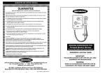
1
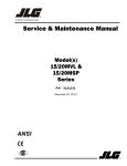
READY
HYDROCAM® System Serial No. ___________
It is important that this manual is read thoroughly prior
to removing the HYDROCAM® system from its shipping container,
begin installation in the tool or operating this product.
READY Technology, Inc.
333 Progress Rd., Dayton, OH 45449
(800) 543-4355 • (937) 866-7200
fax (937) 866-7226
HYDROCAM is protected by USA and International Patents and Trademarks, and is a product of READY Technology, Inc.
Copyright 2001 - 1998 READY Technology, Inc. All rights reserved.
Installation and Service Manual
HYDROCAM
®
Index
GENERAL DESCRIPTION..................................................... page 3
CAM SYSTEMS ................................................................. page 4
RECEIVING INFORMATION ............................................... page 4
H2 SELECTION CHART........................................................ page 5
H1 SELECTION CHART........................................................ page 6
PRE-INSTALLATION CHART ................................................ page 7
INSTALLATION ................................................................. page 9
INSTALLATION WARNINGS ................................................................
INSTALLATION PROCEDURE
H1 PUMP'S, PISTON ROD DRIVER ...........................................
INSTALLATION PROCEDURE
PRE-ASSEMBLED HYDROCAM® SYSTEMS ..................................
INSTALLATION PROCEDURE
NON-ASSEMBLED HYDROCAM SYSTEMS, Nitrogen Return .......
REQUIRED POSITION OF H1 AS COMPARED TO H2 .................
HOSE CONNECTION H1 TO H2 .............................................
page 9
page 9
page 9
page 9
page 11
page 11
OPERATION ..................................................................... page 12
OPERATION - Nitrogen Return .............................................................
page 12
HAZARD WARNINGS ........................................................................
page 12
TROUBLESHOOTING TIPS ...................................................................
page 13
OVERHAUL ...................................................................... page 15
DISASSEMBLY .................................................................................... page 15
CLEANING THE SYSTEM .................................................................... page 15
ASSEMBLY .........................................................................................
page 15
HYDROCAM® REBUILD ..................................................... page 16
H1 PUMP SEAL KIT INSTRUCTION ......................................................
page 16
H2 UNIT SEAL KIT INSTRUCTION .......................................................
page 18
MSDS (USA SYSTEMS ONLY) ...................................... Added to the back of this Manual
HYDROCAM CATALOG...................................... Added to the back of this Manual
2
General Description
HYDROCAM® transfers the vertical action of the
press into a precise cam action using patented
hydraulic technology. Standard components
combine into systems, easing installation in
the tool. The H2 Piercing/Forming unit can be
provided with a machinable front plate that
simplifies custom applications.
HYDROCAM®
action results from the lowering of
the press ram/slide, to activate the H1 Pump’s
piston rod. Hydraulic pressure or force is
transferred through high pressure hose(s) to one
or multiple H2 Piercing/Forming units, extending the H2 unit’s piston rod. The H2 unit has
an adjustable return force using proven nitrogen
technology.
General Description
HYDROCAM® systems incorporate patented
products and processes that are reshaping the
way metal stamping dies are designed and
operated, leading to fewer dies required for part
manufacture. HYDROCAM® is simple to
design, install and operate. HYDROCAM®
removes complexity from piercing/forming and
replaces it with simplicity.
H1
H2
NOTE: HYDROCAM®’s unique design eliminates the thrusting force of the ram/slide from the cam station, allowing the use of
standard L-GIBS to position and guide the station. Providing a guidance system for a HYDROCAM® driven cam station is the
responsibility of the customer. Neither, the H2 unit’s piston rod, nor its front mounting plate assembly is designed to provide cam
station guidance. Contact your representative for application support.
3
Cam Systems
Currently we offer two types of cam systems:
CAMDRIVE® and HYDROCAM®. With both systems,
we eliminate the need for bulky, complicated custom
®
mechanical cams. With our standard HYDROCAM
systems, you can achieve any angle of movement. In
addition, the designer has greater flexibility in the component placement with any HYDROCAM® system.
Hydraulic oil provides for the continuous performance
and long life of the HYDROCAM® system. The oil
automatically lubricates the cylinder wall on every stroke
of the press, reducing friction on the H1 Pump and H2
unit's cylinder seals. Reduced friction increases seal life
and decreases downtime. HYDROCAM’s® use of any
premium ISO V-32 series hydraulic oil extends
maintenance-free service, far superior to any other
mechanical cam system on the market.
With HYDROCAM®, there are no off-die tanks, hoses or
safety problems that result from their use. Also, there is
no wasted time required to assemble, dismantle, store and
find tanks, valves, fittings and hoses.
Important Receiving Information
NOTE: Some HYDROCAM® systems are shipped
pre-assembled with the hydraulic oil already added. With
these systems, make sure that the H1Pump is kept upright
at all times. Failure to do so may result in the loss of
hydraulic oil.
Check the contents of your shipment against the packing
list! Make sure that all items are accounted for before
discarding the container and packaging material.
4
Otherwise, field-assembled parts, accessories or
requested spare parts could be discarded with the
packaging material. In case of damage, advise the
carrier who delivered the shipment. File a claim with
that carrier immediately!
Do not return damaged components for repair or
replacement unless you have contacted your local branch
or distributor for instructions and obtained a "Returned
Goods" (R.G.) number.
How To Select a HYDROCAM ® System for Your Application
1. Determine tonnage required (piercing or forming force, plus stripping force), per unit to perform the necessary work.
Note when using urethane or other mechanical methods for stripping, please add the appropriate stripping force.
2. After you calculate the forces, select the correct H-2 unit(s) required to do the work. Do not exceed 90% of the H-2
unit’s available de-rated force (rated force, less return system force) from the chart below. Include the proper stroke
length needed for each unit.
3. Determine the correct size and number of H-1 pump(s). Group identical H-2 units together (tonnage and stroke),
performing identical work (piercing, forming of flanging). One H-1 pump can operate up to four identical H-2
piercing/forming units (see chart on page 6).
Force of H2 Piercing/Forming Unit
H-2
This chart shows the effect of a nitrogen or oil return
system on the force rating of each H2 unit.
Standard Rate equals the effect of standard
(minimum) return force at 100 bar (1,450 psi) on
the H2 unit’s force. Ideal for piercing applications
that use a customer-provided stripper.
Model
Model
Model
Model
Model
Model
Model
2
3.2
5
7.8
12.5
20
31
Std. Rate
daN
Metric tons
1,787
1.8
2,885
2.9
4,545
4.5
7,094
7
11,319
11.3
18,819
18.8
28,817
28.8
Std. Rate
lbf.
USA tons
3,932
2
6,346
3.2
10,002
5
15,611
7.8
24,906
12.5
41,440
20.7
63,439
31.7
daN
Metric tons
1,698
1.7
2,728
2.7
4,319
4.3
6,740
6.7
10,742
10.7
18,230
18.2
27,727
27.7
lbf.
USA tons
3,732
1.9
5,993
3
9,494
4.7
14,815
7.4
23,609
11.8
40,115
20
60,989
30
Max Rate
Maximum Rate equals the effect of maximum
return force at 150 bar (2,175 psi) on the H2 unit’s
Max Rate
force. Ideal for multiple piercing applications,
special shape piercing, all forming and flanging.
H1 and H2 Selection Guide
Basic Selection:
Working Example: To pierce two holes, 0.250 inch diameter, through 0.125 thick mild steel, with 50,000 psi
minimum tensile strength. We selected a 25mm stroke length for this example. (The working example uses piercing as the
HYDROCAM application. HYDROCAM is also ideal for forming, flanging and other applications.)
Step 1 Calculate the force.
Force = (Hole Ø X (π = 3.1416) X material thickness X material tensile strength) + recommended 10% stripping force
English example: (.250 in. X 3.1416 X .125 in. X 50,000 psi) + 10% = 4,909 lbs. + 491 lbs. = 5400 lbs. (÷ 2000 lbs. = 2.7 U.S. tons)
Metric example: (6mm X 3.1416 X 3mm X 40 daN per mm2) + 10% = 2,262 daN + 226 daN = 2,488 daN (÷ 1000 N = 2.5 metric tons)
Step 2 Select the rate. In this example use the standard rate for
Example Chart
piercing.
H-2
Step 3 Apply the Rule of Ninety: Never exceed 90% of the rated
force. 5400 lbs. ÷ 0.90 = 6000 lbs.
Step 4 Read across the above chart until the rated force exceeds
your Rule of Ninety value. In this example 6,346 lbs.
exceeds 6000 lbs.
Step 5 Read up to the column heading. This is the H2 model you
need. In this example, H2 model 3.2.
Step 2
Model
Model
2
3.2
Std. Rate
daN
Metric tons
1,787
1.8
2,885
2.9
Std. Rate
lbf.
USA tons
3,932
2
6,346
3.2
Max Rate
daN
Metric tons
1,698
1.7
2,728
2.7
Max Rate
lbf.
USA tons
3,732
1.9
5,993
3
Step 5
Step 4
FORCE WARRANTY: The minimum force that a H2 Piercing/Forming unit is warranted to provide is listed in the maximum rate
column. If the customer's determined application force for a cam station’s tonnage exceeds 90% of the maximum rate force, the
next larger or multiple H2 unit(s) must be selected.
5
HYDROCAM® H1 Pump Selection Chart
This chart determines the appropriate H1
Pump for the H2 unit(s) selected. The chart
also lists the H1 Pump’s piston rod travel (mm)
next to the number of identical H2 units
served.
You need to know the H2 model number, the
number of H2 units required and the H2
stroke length before using this chart.
Always use the Rule of Ninety. The chart is based
on using ninety percent of the total volume
(VT) of the H1 Pumps listed, in determining the
number of identical H2 units that can be
supplied by an H1 pump.
Different stroke lengths or different H2 models
may not be used with the same H1 Pump. No
more than four H2 units may operate off a
single H1 Pump.
When two or more identical H2 units are used
to extend a gang pierce bar or forming pad,
each H2 unit must have its own H1 Pump.
NOTE: Piston rod travel may vary slightly. This
results from normal variations in connecting
hose length(s), and the number and style of the
turning fittings.
Use only approved hose and fittings.
H-2
25 mm
Model 2
50 mm
Model 3.2
25 mm
Model 2
50 mm
Step 2
Step 1
25 mm
Model 3.2
Model
H-1
50 mm
5
Model 5
Model
Model
Model
13
20
40
66
1 (12.99)
2 (18.49)
3 (23.98)
4 (22.26)
25 mm
50 mm
1 (25.44)
1 (21.63)
25 mm
Model 20
Model 31
Step 4
3
1 (19.55) 2 (31.60)
4
1 (25.57) 1 (25.57) 2
3
2 (26.48) 3 (35.96) 4
(22.79)
(27.88)
(22.79) 4 (25.59)
(30.43)
(23.55)
2 (22.35)
1 (37.17) 1 (20.05) 3 (29.77) 4 (37.19)
3 (40.90)
1 (26.32) 2 (29.77 4 (52.04)
3 (25.08)
1 (30.92) 2 (27.31) 4 (30.94)
50 mm
75 mm
Model 12.5
3 (25.57) 4 (31.60)
1 (22.33) 2 (37.17) 3 (26.32) 4 (22.35)
25 mm
Model 7.8
3 (29.64)
2 (22.26) 4 (37.02)
3 (21.74)
1 (26.48) 1 (26.48) 2 (23.55)
4 (26.49)
2 (21.74)
1 (35.96) 1 (19.54)
4 (35.99)
3 (28.86)
50 mm
75 mm
50 mm
1 (27.31) 2 (30.94) 3 (42.65)
75 mm
1 (25.08) 2 (42.65)
100mm
1 (30.94) 1 (30.94)
25 mm
50 mm
1 (23.52) 2 (26.45) 3 (35.93)
4 (45.41)
1 (26.45) 2 (45.41)
75 mm
1 (35.93) 1 (35.93)
100mm
1 (45.41)
25 mm
1 (22.29) 2 (37.08)
3 (51.87)
50 mm
1 (37.08)
75 mm
1 (51.87)
100mm
special
1 (12.99)
2 (18.49)
3 (23.98)
1
1
2
1
(18.49)
(16.47)
(25.44)
(25.44)
Here is what you need to order:
Step 3
Locate the H2 unit and its stroke.
In this example: model 3.2, stoke 25mm.
Step 3 Locate the number of H2 units to the right of the stroke
length. The H1 Pump’s piston rod travel (in millimeters)
is listed next to that number in parentheses.
Step 4 Read up to the column heading. This is the H1
model you need. In this example: H1, model 5.
6
Model
8
1 (18.49)
1 (16.47)
2 (25.44)
25 mm
75 mm
Step 1 and 2
Model
5
75 mm
Working Example:
H-2
Model
H-1
QTY
PRODUCT DESCRIPTION
2
H-2-3.2 Piercing unit with 25mm stroke and
front plate
1
H-1-5 Pump with stroke gauge ring
1
RT-2175-CP Nitrogen Control Panel
2
RT701810670-6 Hydraulic Hose 6 foot long
with swivel fittings (specify lengths up to 6 foot)
2
RT52041JC55-6 Nitrogen Hose 6 foot long
with swivel fittings (specify lengths up to 6 foot)
Note:
• Nitrogen return is standard, oil return can be specified as an
option.
• Front plate is standard, direct punch can be specified as an
option.
• Straight fittings will be supplied to connect the hoses when
ordered as a system, elbow fittings can be specified as an option.
Pre-Installation Guide
1. Determine required cam station tonnage (piercing or
forming force, plus total stripping force, plus nitrogen
or oil return force). Do not exceed 90% of the H2
unit’s rated force (listed force, less return system force).
See page 5.
2. Determine the number of H2 unit's needed for that
tool’s applications.
3. Select the H2 unit's stroke from those offered. A
longer stroke could require a larger H2 unit.
4. Group identical H2 unit’s together (tonnage and
stroke). Group identical cam actions together (number,
size or shape piercing units, forming, flanging, notching).
5. Determine timing for the extension, dwell and retracting of the H2 unit's piston rod.
6. Ball Lock Punch applications; Select a 50 mm or longer
stroke H2 unit to provide additional space to remove
the punch.
Selecting the Mounting Location for the
H2 Piercing/Forming Unit(s).
1. Locate the H2 unit(s) in any three dimensional orientation, perpendicular to the work.
2. Provide for hose access to the back and right front side
of the H2 unit. Custom porting is not available.
3. Provide a mounting platform that will support three
times the total working force of the H2 unit. Locate the
H2 unit against a thrust key.
4. The H2 unit is designed to provide force, not guidance.
2. Select an H1 Pump that provides the H2 unit's volume
total within 90% of the H1 Pump's total volume. Do not
exceed 90%. See page 6.
3. The stroke gauge ring can be provided with the H1
Pump to develop the customer-supplied driver (kiss
block) thickness and to ensure precise travel of the H1
Pump’s piston rod.
Note: Machining tolerances may cause the mounting
surfaces of the H1Pump and/or driver to differ from
the drawings. Determine the driver thickness from the
finished surfaces, not the drawings.
Pre-Installation
Selecting the Correct H2
Piercing/Forming Unit
4. One H1 Pump may serve up to a maximum of four
identical H2 units.
Selecting the Mounting Location
for the H1 Pump
1. The H1 Pump's piston rod must be up and perpendicular to the ram/slide. Do not mount the H1 Pump in an
inclined press or an inclined special machine.
2. Locate the H1 Pump’s oil supply ports above the H2
unit’s vent port elevation. See page 11.
3. Locate the H1 Pump anywhere in the die, under the
ram/slide, that provides balance and simple hose
access to the H2 unit(s). Avoid areas using spray lubrication.
4. Locate the H1 Pump within 2 meters (six feet) of the
H2 unit(s).
5. Rotate the H1 Pump prior to mounting to ensure access
and viewing of the Pump’s sight gauge.
NOTE: As with any air, hydraulic or nitrogen cylinder, neither the
H1 Pump nor the H2 unit is designed to withstand side-thrust
forces. Properly guiding the tool and cam station minimize wear
to the cylinders and increase seal life.
5. The H2 unit’s Piston Rod is designed to extend fully.
NOTE: HYDROCAM®’s unique design eliminates the thrusting
force of the ram/slide from the cam station, allowing the use of
standard L-GIBS to position and guide the station. Providing a
guidance system for a HYDROCAM® driven cam station is the
responsibility of the customer. Neither, the H2 unit’s piston rod, nor
its front mounting plate assembly is designed to provide cam station guidance. Contact your representative for application support.
Selecting the Correct H1 Pump
1. The H1 Pump is selected by using the information
developed while selecting the H2 unit(s). (See calculation pages in the HYDROCAM® catalogue.) See page
5.
Special Timing of the H2 Unit’s Piston
Rod Extension, Dwell and Retraction.
Request the help of your representative to select a;
1. Larger H1 Pump to begin cam extension later in the
stroke.
2. Nitrogen cushion to begin cam extension earlier in the
stroke.
3. Sequenced Solenoid Technology (SST) for special timing requirements.
7
Pre-Installation
(continued)
Nitrogen Return System
4. Hydraulic or air cylinder, pressure system for special
machine applications.
1. Always use a control panel.
2. For each H1 Pump, use at least one control panel that
connects that H1’s associated H2 units.
Connecting the H1 Pump, H2
Piercing/Forming Unit(s) and Nitrogen
Return Control Panel. See page 11.
3. Use O-ring style hose fittings.
Note: We understand that a few applications will
exceed this guide. Contact your representative for
application support.
1. Minimize the number of fittings in the hose system.
2. Do not use a hose system that involves a fitting - to
fitting - to fitting series of connections.
3. Hose each identical H2 unit to a H1 Pump with its
own hose. Do not hose in series. Provide simple access
for hose routing. Use only approved hose and fittings.
H1 Pump
Driver
(not supplied)
4. Provide additional hose length to ensure appropriate
radius and safe routing. Avoid high spots in the oil
hose route that will trap and create air pockets.
Piston
Stroke Gauge
Ring
5. Maximum hose length is 2 meters (six feet). Do not
substitute the supplied hydraulic hose with a smaller
or lighter duty hose.
Fill Port
Exhaust Valve
6. Rotating the H1 Pump 45° may simplify hose routing.
7. Avoid turning fittings. If a hose turn requires a turning
fitting, select a 45° fitting as a first choice and a 90°
fitting second. Use only BSPP-style fittings.
Body
Sight Gauge
H1
Oil Level
(4) Oil
Supply
Ports
Base
H2 Unit
Vent Plug
Oil Supply Port
Piston
Nitrogen
Inlet Port
Anti-rotational
Pillars
H2
Thrust Key
(not supplied)
8
Body
Bronze
Bushing
Side View
Front
Mounting Plate
Front View
Front Mounting Plate
(plate is machinable)
Installation
PROVIDING A GUIDANCE SYSTEM FOR THE
PIERCING OR FORMING STATION IS THE
RESPONSIBILITY OF THE CUSTOMER. NEITHER
THE H2 PIERCING/FORMING UNIT'S PISTON ROD
NOR ITS FRONT MOUNTING PLATE ASSEMBLY IS
DESIGNED TO PROVIDE CAM GUIDANCE.
Installation Warnings
1. HYDROCAM’s® H1 Pump must be set in the die or
press in a vertical position with the piston rod up and
perpendicular to a horizontal ram/slide.
®
2. Never stroke a HYDROCAM system unless all
components are properly mounted and nitrogen is
added to the return system.
®
3. HYDROCAM’s H1 Pump must be set above the
elevation of H2 Piercing/Forming unit(s). See page 10.
4. The tool must include stop blocks to prevent over-travel
of the HYDROCAM’s® H1 Pump's piston rod.
5. Never store the tool in a die closed position or depress
the piston rod of the HYDROCAM’s® H1 Pump(s) during storage.
6. Never loosen a hose fitting if the return system is
under nitrogen pressure or the H2 unit's piston rod is
extended.
Installation Procedure H1 Pump's Piston Rod Driver
The H1 Pump's piston rod travel is critical to the successful
operation of the HYDROCAM® system.
1. Machine smooth and parallel, the tool’s mounting
surfaces for the H1 Pump (lower) and the customer-supplied driver (upper). The diameter of the driver's contact
surface is a minimum of twice the diameter of the H1
Pump's piston rod. This contact surface must be smooth
and parallel with no mounted holes. Use a Rockwell
45C plate for the driver.
2a. If the H1 Pump’s, stroke gauge ring is available,
mount and use it to develop the travel of the H1
Pump's piston rod. The measurement from the base of
the H1 Pump, to the top of the mounted stroke gauge
ring determines the die-closed position of the customersupplied driver’s contact surface. Use this measurement
to calculate the length of the customer-supplier driver.
We recommend that the stroke gauge ring be removed
and stored on the tool prior to stroking the H1Pump.
OR ...
2b. Use the formula (Calculating the H1 Piston Rod
®
Travel) from the HYDROCAM catalogue to determine
the length of the H1 Pump's piston rod travel. See
page 6 for the H1 selection and travel of piston. The
measured height from the base of the H1 Pump, to the
top of the piston rod extended, less the calculated
piston rod travel, locates the die closed position of the
contact surface of the customer-supplied driver. Use this
measurement to calculate the length of the driver.
Installation
Before attempting to install or service, READ
THIS MANUAL THOROUGHLY.
Installation Procedure - Pre-Assembled
HYDROCAM® Systems
Installation of a PRE-ASSEMBLED SYSTEM is the same as
the procedure for installing a NON-ASSEMBLED SYSTEM.
Begin at step 2. of that section, noting that the hydraulic
oil has previously been added to the system. With the
nitrogen pressure fully discharged, the H2 unit's piston
rod may be extended by carefully depressing the H1
Pump's piston rod with a manual press.
Installation Procedure - Non-Assembled
HYDROCAM® Systems, Nitrogen Return
1. Check to see that the system's H1 Pump, H2
Piercing/Forming unit(s), hose assemblies and system
accessories are not pre-assembled (see above).
2. Locate the H2 unit in the desired position. The part
number RTAUX-1000 Hand/Fill pump can be
connected to the H2 unit's hydraulic oil port to move
the piston rod, easing the alignment of the customerprovided piercing or forming station and guidance
system. Locate the H2 unit against a thrust key.
3. When alignments are correct, set and tighten four
mounting bolts and two dowels in the holes provided
on the H2 unit. Follow the same procedure for each
additional H2 unit. Note: If access to the H2 unit is
limited, final mounting can wait until after hydraulic oil
has been added to the system.
4. Locate the H1 Pump in the desired position, then set
and tighten four mounting bolts. The H1 Pump must be
located at a higher elevation than the H2 unit. Note:
If access to the H1 Pump is limited, final mounting may
wait until after hydraulic oil has been added to the
system. Rotate the H1 Pump prior to mounting to ensure
access and viewing of the Pump’s sight gauge. See
page 11.
9
Installation (continued)
5. Connect the H1 Pump and the H2 unit(s) with hose
and fittings, providing additional hose length to assure
appropriate radius and safe routing. Do not allow high
spots in the hose routing. Use Blue lock-titeTM on all
threads and tie-downs on the hose(s).
6. With the H2 unit's piston rod in the full-back (die-open)
position, slowly charge the H2 unit(s) with 100 bar
(1450 psi) of nitrogen using the control panel or the
RTUAL-04.0-QDM service tool. To install the control
panel, the cover plug and inlet valve must be removed
before installing the adapter fitting on the front (bronze)
bushing of the H2 unit(s).
7. Adding ISO V-32 Series Hydraulic Oil to the System:
A. To prevent contamination from entering the hydraulic
system, loosen the fill port plug on top of the H1 Pump,
but do not fully remove it. Then, loosen the vent port
plug on top of the associated H2 unit(s), but do not
fully remove it. Remove the plugs only when hydraulic
oil is being added or air is being bled. Depending on
the location of the H1 Pump and its H2 unit(s), two
people may be needed to complete the following tasks.
B. With a squeeze bottle or the RTAUX-1000 Hand/Fill
pump, fill the system slowly with the hydraulic oil,
through the fill port on top of the H1 Pump. While one
person is adding the hydraulic oil, the other will open
fully, the lowest mounted H2 units’ vent port until a continuous flow of pure hydraulic oil (no air bubbles) flows
from the vent port, then replace the port plug. Repeat
the same with any additional H2 units(s), moving from
the lowest to the highest mounted. After all H2 vent
plugs are in place, add hydraulic oil until it centers in
the H1 Pump’s sight gauge. Do not over-fill the system
with hydraulic oil.
C. Beginning with the lowest mounted, separately and
carefully, reopen the vent ports on each H2 unit. Let it
open until no air bubbles rise out of the vent port. If the
hose assembly was properly laid-out, subsequent to
adding hydraulic oil, all air bubbles are now out of the
system. If care was not taken to ensure the smooth fall
and rise of the hose assembly, the hose system must be
adjusted and the process repeated.
D. Check the H1 Pump’s sign gauge and add hydraulic
oil, if needed. Do not overfill the H1 Pump. Center the
hydraulic oil in the sight gauge, replace and tighten the
H1 fill port plug.
10
E. Check alignments and check to be certain all fittings
are tightened.
8. Stroke the H1 Pump three times, ensuring that the
H2 unit’s piston rod fully extends, and at the die open
position, the hydraulic oil level is centered in the H1
Pump's sight gauge. Also, check that the H2 unit's
piston rod returns to its full-back (die open) position.
Add additional hydraulic oil, if need, as stated in
step 7.
Your hydrocam system is now ready for production.
HYDROCAM systems with the H2-2
unit(s) or systems with very long
Hydraulic Drive Hose Assemblies can
be more difficult to fill.
The following will assist:
a. First, discharge the nitrogen return system. With a pry
bar, carefully cause the front mounting plate to move it
forward about 3 mm (1/8”). It is not necessary, nor
recommended that the front mounting plate be moved
open any farther.
b. Complete Steps A-D listed above, understanding that
these systems will take longer to fill. Setting the H1
Pump much higher than the H2 unit(s) while adding
hydraulic oil to the system will aid in filling these systems. After completing Step D above, return and complete Step c, listed below.
c. With the H1 Pump’s fill port open, push the H2 unit’s
front mounting plate(s) back into the full-back (die open)
position. Next, charge the nitrogen return system. With
the H2 unit’s front mounting plate(s) fullback, check the
oil level in the H1 Pump’s sight gauge. The oil level
may be too high. Drain excess oil from the system.
Complete Step E listed above.
Complete assistance is available should the need arise.
contact your representative for details.
THE MOST COMMON HYDROCAM® OPERATING
PROBLEM IS AIR CAUGHT IN THE HOSE SYSTEM.
ENSURE THAT YOU HAVE PROPERLY MOUNTED
THE H1 PUMP, AVOIDED HIGH SPOTS IN THE
HOSE SYSTEM AND BLED THE SYSTEM OF AIR.
Installation (continued)
MODEL
HYDROCAM
HYDROCAM
HYDROCAM
HYDROCAM
HYDROCAM
HYDROCAM
Sight Gauge
Nitrogen Inlet Port
NOTE: We understand that a few applications will exceed this guide.
Contact your representative for application support.
H1-5
H1-8
H1-13
H1-20
H1-40
H1-66
H DIMENSION
21 mm (0.83 in)
25 mm (0.98 in)
25 mm (0.98 in)
25 mm (0.98 in)
30 mm (1.18 in)
40 mm (1.57 in)
Installation/Operation
Required position of H1 as compared to H2
Hose Connection H1 to H2
Wrong
Right
NOTES:
11
Operation
®
Standard HYDROCAM systems operate using a simple
hydraulic driven extension with a nitrogen return and
require no special conditions or procedures to operate
them. Ensure that the PRE-INSTALLATION GUIDE and
INSTALLATION sections of this manual have been followed
prior to operation.
During normal operation, occasionally inspect the
hydraulic oil level by viewing the sight gauge on the H1
Pump’s body. The oil level should be centered in the sight
gauge. In addition, check the nitrogen pressure 100 bar
(1450 psi) in the H2 Piercing/Forming unit's front
(bronze) bushing on the control panel or with the RTUAL04.0-QDM service tool. (Note: The installation of the
RTUAL-04.0-QDM service tool will automatically lower the
nitrogen pressure in the H2 unit as the nitrogen fills the
additional volume in the service tool.)
As with any air, hydraulic or nitrogen cylinder, neither
the H1 Pump nor the H2 unit is designed to withstand
side-thrust forces. Properly guiding the tool and cam
station will limit damage to the cylinders and increase
seal life.
®
THE MOST COMMON CAUSE OF A HYDROCAM
SYSTEM NOT OPERATING IS AIR CAUGHT IN THE
HOSE SYSTEM. ENSURE THAT YOU HAVE PROPERLY
MOUNTED THE H1 PUMP, AVOIDED HIGH SPOTS IN
THE HOSE SYSTEM AND BLED THE SYSTEM OF AIR.
Complete engineering assistance, seminars and service
support are available should a need arise for any of our
full line of metal forming products. Contact your
representative for details.
Hazard Warnings
• ONLY PERSONNEL WITH THOROUGH
KNOWLEDGE OF HYDRAULIC AND/OR
NITROGEN CYLINDER SYSTEMS SHOULD
ATTEMPT TO SERVICE OR REPAIR THIS SYSTEM.
• BEFORE ATTEMPTING TO CHARGE OR
EXHAUST THIS OR ANY SYSTEM USING HIGH
PRESSURE NITROGEN, HYDRAULICS, OR USE
OTHER EQUIPMENT CONTROLLING OR STORING ANY COMPRESSED GAS. ALWAYS USE
APPROVED EYE AND EAR PROTECTION.
• SLOWLY EXHAUST ALL NITROGEN FROM THIS
SYSTEM BEFORE SERVICING. MAKE SURE ALL
PRESSURE HAS BEEN COMPLETELY EXHAUSTED
BEFORE ATTEMPTING TO REMOVE ANY
FITTINGS, HOSES, H1 PUMP, H2
PIERCING/FORMING UNIT(S), CONTROL PANEL
OR OTHER COMPONENTS.
12
•EXCEPT FOR AN EMERGENCY, ALWAYS
SLOWLY CHARGE OR EXHAUST THIS OR ANY
NITROGEN SYSTEM. RAPIDLY CHARGING OR
EXHAUSTING A NITROGEN SYSTEM COULD
RESULT IN DAMAGE TO EQUIPMENT AND/OR
INJURY TO PERSONNEL.
• DO NOT SUBSTITUTE ANY COMPONENT IN
THIS SYSTEM! IMPROPER SUBSTITUTIONS MAY
RESULT IN PERFORMANCE PROBLEMS AND/OR
SAFETY HAZARDS.
• DO NOT ATTEMPT TO REUSE ANY
COMPONENT THAT IS, OR APPEARS TO BE
DAMAGED. THIS CAN RESULT IN POTENTIAL
PERFORMANCE PROBLEMS AND/OR SAFETY
HAZARDS.
• USE ONLY A PREMIUM ISO V-32 SERIES
HYDRAULIC OIL.
Troubleshooting Tips
NOTE: (***) Indicates repair of the component is in
question. HYDROCAM® components must be replaced
with an exact duplicate part. Failure to do so may result
in serious injury, as well as cause damage to the
HYDROCAM® system or tool.
PROBLEM: H2 Unit’s Piston Rod is not
Extending to its Full Stroke.
CAUSE: There is air in the hose system. Air has not
been bled from the system. There is a high spot in the
hose system trapping air. The H1 Pump is not mounted
above the H2 unit(s). Adjust and bleed the air from the
system. See pages 10 and 11.
CAUSE: The H1 Pump is undersized. Volume Total of
the H2 unit(s) is greater than 90% of the H1’s Total
Volume. See page 6.
CAUSE: The H1 Pump’s piston rod has been
continuously over-stroked, weakening the safety relief
valve. Contact your representative!
PROBLEM: H2 Unit’s Piston Rod is not
Returning to its Full-Back (Die-Open)
Position.
CAUSE: The cam station does not have a guidance
system causing the station to bind the H2 unit’s piston
rod. Install a cam station guidance system. The H2 unit
is designed to provide force not guidance! See page 7.
CAUSE: Multiple H2 units are hosed in series. Re-hose
using a single hose from each H2 unit to its own H1
Pump port. An excessive number of fittings have been
used. Eliminate or reduce the number of turning fittings.
The supplied hose was substituted with a smaller ID
hose. Use only approved hose and fittings.
CAUSE: Check the nitrogen pressure, 100 bar (1,450
psi). If the nitrogen pressure is low, charge the system to
100 bar (1,450 psi) and check for nitrogen leaks in the
system. If nitrogen pressure is very low and/or frequent
charging is required. Rebuild the H2 unit with the
appropriate seal kit.*** If the H2 unit is self-contained
and the inlet valve is leaking, replace it with new.***
If the nitrogen pressure is 100 bar (1,450 psi), check
the H1 Pump (see below).
CAUSE: The H1 Pump’s hydraulic oil level is not correct. The oil level should be centered in the H1 Pump's
sight gauge, add or remove excess oil and bleed air
from system.
CAUSE: The H1 Pump's hydraulic oil level is too high.
The oil level should be centered in the H1 Pump's sight
gauge. Remove excess oil and bleed air from the
system.
CAUSE: The H1 Pump's piston rod is not being
travelled the correct distance. Recheck using the stroke
gauge ring that the H1 Pump’s piston rod travel is
correct. Adjust (lengthen or shorten) the H1Pump's
piston rod travel. Contact your representative for
support. See page 6.
CAUSE: There is an internal nitrogen leak in the H2
unit causing the hydraulic oil in the system to foam.
Rebuild the H2 unit.
CAUSE: The H2 unit is undersized for this application.
Check that the required force (piercing or forming force
+ stripping force + return force) is not beyond 90% of
the maximum rated tonnage capacity of H2 unit. See
page 5.
Hazard Warnings/Troubleshooting Tips
THE MOST COMMON CAUSE OF A HYDROCAM®
SYSTEM NOT OPERATING IS AIR CAUGHT IN THE
HOSE SYSTEM. ENSURE THAT YOU HAVE PROPERLY
MOUNTED THE H1 PUMP, AVOIDED HIGH SPOTS IN
THE HOSE SYSTEM AND BLED THE SYSTEM OF AIR.
PROBLEM: H1 Pump's Piston Rod is not
Returning to a Full-Up (Die-Open)
Position.
CAUSE: The H1 Pump's hydraulic oil level is too high.
The oil level should be centered in the H1 Pump's sight
gauge. Remove excess oil and bleed air from the
system.
CAUSE: H1 Pump's piston rod is being over-travelled
causing the 400 bar (5,802 psi) safety relief valve to
activate on each stroke, resulting in hydraulic oil not
returning back into the H1Pump's lower chamber. With
the stroke gauge ring, adjust (shorten) the H1 Pump's
piston rod travel and bleed air from the system. See
page 6.
13
Troubleshooting Tips (continued)
CAUSE: Hydraulic oil has filled the H1 Pump's upper
chamber because the tool was stored in a die-closed
position. See Installation Warnings, page 9. Carefully
remove the fill port plug and exhaust valve on top of the
H1 Pump using a 5mm hex wrench and an 11mm thinwall socket wrench, then slowly pull the piston rod up
using a dowel puller (M8 for a H1-5 Pump, M10 for
the H1-8 and H1-13 Pumps, M16 for a H1-20 Pump,
M20 for the H1-40 and H1-66 Pumps). Check that
the hydraulic oil level is centered in the H1 Pump's sight
gauge. Replace and tighten the fill port plug and
exhaust valve.
CAUSE: Hydraulic oil is by-passing the H1 Pump
base's green O-ring seal. Rebuild the H1Pump. ***
See page 16.
CAUSE: The H1 Pump's piston rod return spring is
weak, damaged or undersized. Replace with a new,
unpainted return spring. ***
CAUSE: If the H2 is self-contained and the inlet value
is leaking, replace it with new. Note: Nitrogen return
systems that use a control panel do not have an inlet
valve in the H2 unit!
CAUSE: Nitrogen fitting(s) is leaking or breaking. The
hose fitting(s) was never tightened or over-tightened
during assembly. Replace any leaking hose or fitting
with new. Use O-ring style hose fittings. Use Blue locktiteTM on all threads and tie-downs on the hose(s). An
excessive number of fittings have been used. Eliminate
or reduce the number of fittings. Use only approved
hose and fittings.
CAUSE: Scratched H2 unit piston rod, damaged
and/or leaking components, seals, hoses, fittings or
components on the control panel. Follow standard leak
tests to determine location of the leak. Replace any
damaged or leaking part with new. H2 unit was rebuilt
using the wrong or damaged seal kit components. ***
System is in need of general overhaul. ***
PROBLEM: Loss of Hydraulic Oil.
PROBLEM: Rupture Plug Failure.
CAUSE: Hydraulic oil was accidentally drained. The
oil level should be centered in the H1 Pump's sight
gauge, add oil and bleed air from system.
CAUSE: Hydraulic oil fitting(s) is leaking or breaking.
The hose fitting(s) was never tightened or over-tightened
during assembly. Replace any leaking hose or fitting
with new. Use Blue lock-titeTM on all threads and
tie-downs on the hose(s). An excessive number of fittings
have been used. Eliminate or reduce the number of
turning fittings. Use only approved hose and fittings.
CAUSE: Scratched H1 or H2 piston rod, damaged
components, seals, hoses or fittings are causing a leak.
Follow standard leak tests to determine the location of
leak. H1 Pump or H2 unit rebuilt using the wrong or
damaged seal kit components causing leaks. ***
PROBLEM: Loss of Nitrogen Pressure.
CAUSE: Nitrogen pressure is low, resulting from the
normal loss following the installation of the RTUAL-04.0QDM service tool. Recharge system.
14
CAUSE: Nitrogen pressure was accidentally reduced.
Recharge system.
CAUSE: Nitrogen pressure charged too high, maximum
pressure is 150 bar (2175 psi). A hose has been
crushed or has too tight a radius. Defective, weakened
or incorrect rupture plug. *** Die lubricant has entered
the system (see below). Eliminate source and rebuild
system.
PROBLEM: Hydraulic Oil Level in H1
Sight Gauge Appears to be Rising.
CAUSE: Die lubricant is entering the system through the
H1 Pump or H2 unit(s). Eliminate source of the die
lubricant and rebuild system.
PROBLEM: The Nitrogen Charge
Pressure Indicator on the Control Panel
does not rise when the ram/slide is set
at Die-Closed Position.
CAUSE: The Inlet valve was not removed from the H2
unit during installation of the nitrogen return system's
hose assembly. Using the RTUAL-04.0-QDM service
tool, exhaust all nitrogen from the H2 unit and remove
the inlet valve.
Overhaul
Disassembly
1. WITH THE CONTROL PANEL OR THE RTUAL-04.0QDM SERVICE TOOL, SLOWLY EXHAUST ALL
NITROGEN FROM THE SYSTEM BEFORE SERVICING
OR HANDLING. ENSURE COMPLETE DISCHARGE OF
PRESSURE BEFORE ATTEMPTING TO REMOVE ANY
H1 PUMP, H2 UNIT(S), CONTROL PANEL, HOSES,
FITTINGS, OR ANY OTHER SYSTEM COMPONENTS.
®
2. To begin disassembly of the HYDROCAM system,
locate and remove hydraulic oil hose fittings and port
plug(s) from the H1 Pump and H2 unit(s). Drain the
hydraulic oil completely out of the system. CAUTION:
Do not allow the hydraulic oil to drain on to the floor,
as it is extremely slippery. Do not reuse the hydraulic
oil, as it may be contaminated. Consult the MSDS form
for the ISO V-32 series hydraulic oil that you are using
for additional handling information. For cylinder
disassembly refer to the instructions included in this
manual, see H1 Pump or H2 unit's seal kit section,
pages 16 and 18.
guidelines to reinstall a HYDROCAM® system. Prior to
installation, make sure that all seals, sealing surfaces
and O-rings are lubricated. Leave the two H1 Pump
valves on top of the pump body loose so that ISO
V-32 series hydraulic oil can be added to the Pump.
Failure to follow the INSTALLATION section will result in
®
damage to the HYDROCAM system.
3. The H1 Pump was designed to operate in a very
specific orientation (vertical). To avoid loss of hydraulic
oil, damage to equipment and/or injury to personnel,
®
never operate this HYDROCAM component in any
other position.
4. Use only a premium ISO V-32 series hydraulic oil.
Substitution can cause performance problems and/or
safety hazards.
Troubleshooting/Overhaul
Before attempting any service, read the sections
on INSTALLATION and HAZARD WARNINGS and
THIS MANUAL THOROUGHLY.
5. Prior to operation, follow standard leak tests to
determine if there is any nitrogen or hydraulic oil leaks.
®
6. Never stroke a HYDROCAM system until all
components are properly mounted and tightened.
NOTES:
Cleaning the System
1. Always remove all plugs, fittings and accessories
before cleaning the components. Using solvent, thoroughly clean the disassembled H1 Pump, H2 unit(s)
and system components. Carefully blow-dry the
components with filtered compressed air. Inspect them
for wear as described in the seal kit instructions. If in
doubt, replace a worn component rather than have a
premature failure in a newly rebuilt system.
2. When one major part of the system needs to be rebuilt,
rebuild them all, to assure maximum service life and
minimum downtime.
Assembly
1. Rebuild the H1 Pump and H2 unit(s) according to the
instructions included in this manual. See the H1 Pump
or H2 unit’s seal kit section, pages 16 and 18.
2. Refer to the PRE-INSTALLATION GUIDE and
INSTALLATION sections in this manual for proper
15
®
HYDROCAM Rebuild
H1 Pump Seal Kit
Instruction
3
BEFORE ATTEMPTING TO SERVICE OR REPAIR A
HYDROCAM® SYSTEM, READ THE INSTALLATION AND
SERVICE MANUAL THOROUGHLY. PLACING SPECIAL
ATTENTION TOWARD THE HAZARD AND SAFETY
WARNINGS LOCATED THROUGHOUT THE MANUAL. IF
YOU DO NOT HAVE THIS MANUAL, CONTACT YOUR
REPRESENTATIVE.
Before disassembly of the H1 Pump, verify that the correct
seal kit is on-hand and that it is complete. Thoroughly
review the instruction and drawings included with this seal
kit.
1. Disconnect the hose fitting(s) and/or port plug(s)
attached to the four pump base sides. Using an 11mm
thin-wall socket wrench and a 5mm hex wrench,
remove the exhaust valve and fill port plug on top of
the pump body. Empty the remaining hydraulic oil.
4
2. After carefully removing the sight gauge, use a pin
spanner wrench to unscrew the pump body from the
pump base. If a strap wrench is used, place it very
close to the top of the pump body. Placing a strap
wrench close to the pump base will exert greater force
on the threads making removal difficult.
3. Carefully guide the piston rod out the bottom of the
pump body. Taking care not to damage the piston rod
or the pump body bore.
4. Note the colour, size, orientation and location of each
seal. Remove all seals from the pump body and pump
base, taking care not to damage the sealing surfaces.
5. High-pressure wash or solvent-clean the components
that will be reused. Carefully blow-dry the components
with filtered compressed air. Visually inspect the piston
rod, pump body and pump base sealing surfaces.
Replace any part that is damaged, worn, scratched or
contains imperfections.
5
16
6. Carefully install the new seals in their proper location
and orientation. Make sure that all seals, O-rings and
sealing surfaces are lubricated before installation.
®
HYDROCAM H1 Pump Rebuild (continued)
Rebuild
7. Lubricate with oil and carefully guide the piston rod
fully into the pump body. Install the unpainted return
spring in the base of the piston rod and install the
pump body assembly on the pump base and tighten
firmly. Install the two H1 Pump valves on top of the
pump body loosely, so that hydraulic oil can be added
during tool installation. Carefully install the sight gauge.
8. Refer to the PRE-INSTALLATION GUIDE, INSTALLATION
and OVERHAUL sections of the INSTALLATION AND
SERVICE MANUAL for proper guidelines to reinstall this
®
HYDROCAM component. Failure to follow those
guidelines will result in performance problems, damage
to the HYDROCAM® system, equipment and/or injury
to personnel.
H1 Pump
17
®
HYDROCAM Rebuild
H2 Piercing/Forming Unit
Seal Kit Instruction
1
BEFORE ATTEMPTING TO SERVICE OR REPAIR A
HYDROCAM® SYSTEM, READ THE INSTALLATION AND
SERVICE MANUAL THOROUGHLY, PLACING SPECIAL
ATTENTION TOWARD THE HAZARD AND SAFETY
WARNINGS LOCATED THROUGHOUT THE MANUAL. IF
YOU DO NOT HAVE THIS MANUAL CONTACT YOUR
REPRESENTATIVE.
Before disassembly of the H2 unit(s), verify that the correct
seal kit is on-hand and that it is complete. Thoroughly
review the instruction and drawings included with this seal
kit.
2
1. Completely discharge the nitrogen from return system
using the control panel or the RTUAL-04.0-QDM service
tool. If using a control panel with a nitrogen return
system remove from the H2 unit's seal kit, the inlet
valve and discard it.
2. Disconnect the hose fitting(s) and vent plugs attached to
the H2 Body and front (bronze) bushing. Remove the
front plate with its columns by removing the metric
socket cap screw centered on the front plate.
3. Remove the four metric socket cap screws on the front
of the (bronze) bushing and carefully separate the front
bushing from the body. Take care not to damage the
piston rod or sealing surfaces while the body, front
bushing and piston rod are separated.
3
4. Note the colour, size, orientation and location of each
seal. Remove the seals from the piston rod, body and
front bushing, taking care not to damage the sealing
surfaces.
5. High-pressure wash or solvent-clean the components
that will be reused. Carefully blow-dry the components
with filtered compressed air. Visually inspect the piston
rod, body and front bushing sealing surfaces. Replace
any part that is damaged, worn, scratched or contains
imperfections.
6a
18
6. Carefully install the new seals from the seal kit in their
proper location and orientation. Check to see that all
seals, guide rings, O-rings and sealing surfaces are
lubricated before installation. Place the front U-cup seal
in the front (top) of the front bushing's seal chamber.
Place grease on the U-cup seal, leaving the lower
portion of the seal chamber open.
®
HYDROCAM H2 Unit Rebuild (continued)
6b
Rebuild
PISTON ROD SEAL INSTALLATION TIP: Immerse
the U-cup seals to be installed on the piston rod in hot
hydraulic oil for several minutes prior to placing them
on the piston rod. This will simplify the expansion of
the U-cup seal as it slides onto the piston rod and into
its seal chamber. (Note: Check that the orientation of
the U-cup seal is correct prior to placing it on the piston
rod. The two U-cup seals sit on either side of the piston
guide ring and must be in opposing directions.)
7. Lubricate with oil and carefully guide the piston rod
into the front bushing and install the bushing assembly
in the base. Install the four metric socket cap screws in
the front of the bushing, then install the front plate with
its columns. Align the columns by indicating them
parallel to each other. Recheck the parallelism of the
columns prior to torquing the metric socket cap screws
on the front bushing and centered on the front plate.
Use blue Lock-tite™ on all threads.
8. If the H2 unit is using a self-contained nitrogen return
and charged using the RTUAL-04.0-QDM service tool
or using the optional oil return system, install a new
inlet valve in the front bushing's nitrogen port. Do not
install an inlet valve if the H2 unit will be used with a
nitrogen return control panel.
7
9. Refer to the PRE-INSTALLATION GUIDE, INSTALLATION
and OVERHAUL sections of the INSTALLATION AND
SERVICE MANUAL for proper guidelines to reinstall this
HYDROCAM® component in the tool or press. Failure
to follow those guidelines will result in performance
problems, damage to the HYDROCAM® system,
equipment and/or injury to personnel
8
H2 Unit
Venting
Plug
Piston
Guide Ring
Front U-cup
Seal - nitrogen
H2 Body
(steel)
Front Bush
Body Seal
Bush U-cup
Seal - nitrogen
Rod Scraper
Seal
Oil Port
Piston
Plug
Rear U-cup
Seal - oil
Front Bush
bronze)
Piston
19
READY
All Our Products Are Available Globally
Our factories and offices:
U.S.A. • Mexico • U.K. • France • Belgium • Germany • Sweden
• Netherlands • Singapore
READY TECHNOLOGY, Inc.
333 Progress Rd. • Dayton, OH 45449
(800) 543-4355 • (937) 866-7200 • FAX: (937) 866-7226
© 2001 READY TECHNOLOGY, INC.
CATALOG # 1101