1
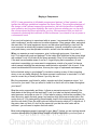
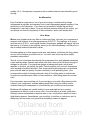
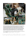
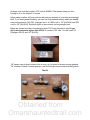
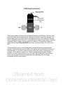
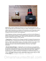
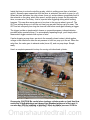
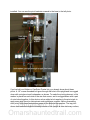
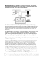
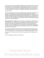
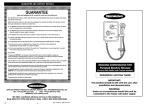
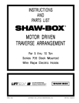
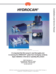
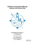
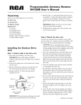
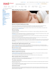
 http://www.phantasmechanics.com/air/index.html Haunting With Compressed Air, Part 1 Updated 11/20/2007
Compressed air offers a number of advantages over electrical actuators for haunts, and
has accordingly been used for many decades in dark attractions. The hiss of air
accompanying a scare was a hallmark of the dark rides I grew up with. Utilizing
compressed air is the most efficient method to produce sudden and startling kinetic
effects. It is safe to use on damp ground outdoors, allows quick and powerful
movements without the risk of blown fuses or overheating, and allows for the relatively
simple construction of devices that would be expensive or impossible to duplicate using
other methods.
The amount of force generated at the output of an air actuator (usually a piston and rod
housed in a cylinder and connected to an object to be moved) by even a modest
amount of input pressure can be amazing. If you've never considered an air system
because it seemed too daunting, peruse this article and discover the basics. It may be
just what you're looking for.
The Basics
The basics of compressed air power systems are not hard to understand. A compressor
feeds air into a holding tank, much as a well pump feeds water into a reservoir.
Fortunately, air is compressible (unlike water) and a lot of it can fit into a relatively small,
stout tank. The tank is essential to the proper functioning of the system, and the tank's
pressure is always higher than the pressure required by any single device connected to
it.
Attached to a fitting on the tank is a limit switch that shuts off the compressor when the
tank has been filled to its highest safe pressure, along with a spring-loaded valve, which
releases excess pressure from the tank if the limit switch fails. On the main outlet is an
adjustable regulator, which reduces the tank's pressure to that required by the
connected system.
Obtained from
Omarshauntedtrail.com
On this regulator are two gauges, one reading tank pressure and the other showing
output pressure. The regulator setup may vary, depending upon the size and cost of the
equipment, but it is essential to be able to read both tank pressure and the output
pressure of the regulator.
The entire system we will describe is shown below:
The compressor's output line should be coupled with
a filter/drier trap unit (shown at right) which is
designed to remove oil and any foreign particles that
may have been introduced by the compressor, and is
also intended to collect any water which condenses
out of the air as it passes through. (As the pressure
and temperature of the air drops when passing into
this larger enclosure, water vapor naturally passes
into its liquid state.)
Water and debris - including tiny metal particles shed
by the compressor's mechanism - contribute to rust,
corrosion and wear, while oil causes deterioration in rubber parts and seals. Thus, a
filter is very important for reliable system operation. These devices consist of a
perforated cylindrical part covered with a fine membrane, housed inside a glass or
plastic cup which is often covered with a mesh or cage to prevent injury to the operator
in the event of shattering. At the bottom of the glass is a tap valve, which may be
opened during operation to expel water and oil.
Obtained from
Omarshauntedtrail.com
The trap/filter must capable of handling the highest pressure required by any device
downstream. They are typically rated for pressures between 100 and 200 P.S.I. For our
purposes, this is more than adequate. The unit should be checked regularly, and the
excess water must be bled off before it reaches the level of the filter. In humid climates,
this can occur frequently if the trap is small.
As air lines run to multiple applications, they branch by means of T-connectors and
valves on the main line. The valves allow any single application to be shut off as
needed, allowing the system to continue operating. If a single actuator (a device
converting air pressure to kinetic movement) is connected to a branch, the valve may be
electrically activated for automation purposes. A secondary regulator (and, in a large
system, a smaller filter/trap) may be required at this point. Typically, the actuator's feed
pressure must be limited to a lower pressure than the higher feed pressure, as this is
usually higher than the actuator requires or can safely handle.
As described above, actuators include cylinder-piston assemblies, but also include air
turbines, inflatable bladders, and spray nozzles. (In the context of a haunted attraction,
you can move an object suddenly, inflate a figure which materializes out of an enclosure
in the blink of an eye, cause an object or surface to vibrate, or startle your guests with a
blast of air.)
When several closely proximal branches are required, multiple-tap connector blocks,
known as manifolds, are employed. These may optionally be equipped with manual or
electric valves that control the flow of air to each output line individually. Valved
manifolds are useful for automating the movements of a device comprised of interacting
actuators, such as an animatronic figure. When a manifold is used, a main regulator
may be placed at its input to control the overall pressure feeding the device, along with
other regulators at each actuator in the setup, where necessary.
The master air storage tank at the compressor holds a surplus of air as a buffer. Its
pressure should not decrease significantly, even if a number of low pressure devices all
fire at once. At each device that requires a strong, sustained surge when acting, a small
in-line tank or reservoir (spherical or cylindrical) is installed, such that extra air does not
need to travel a long distance through a restricted line to reach it. Unlike electricity, air is
slowed significantly when it must travel through long, narrow conductors. Without
reservoirs, actuators may work more slowly and unpredictably, especially if they are
triggered often, or if several devices are triggered at once
What does all this mean to the phantasmechanic? Here are some tips on setting up
your system.
Obtained from
Omarshauntedtrail.com
Buying a Compressor
NOTE: A new generation of affordable compressors features 'oil free' operation, and
typifies the offerings available at suppliers like Home Depot. The principle advantage of
this design is that it allows inexpensive construction, but with the sacrifice of relatively
quiet operation and long-term reliability. Be sure to discover whether you can live with
the noise produced by these units before you buy. We recommend that you look into
compressors featuring the traditional oil-filled crankcase if you intend to use air power in
a commercial haunt.
If you are just beginning to experiment with air power, I recommend that you consider a
used compressor, as new ones can be rather expensive. Shop garage sales, and watch
the want-ads. Call rental equipment stores, and ask about purchasing a used unit. Be
sure to acquire an electrically powered compressor. Internal combustion motors are
noisy and messy, must be operated outdoors, and will ruin the ambience of your haunt.
When you examine a used compressor, give it a thorough going-over. How does it
look? Is it caked with gunk and garbage? Is the intake filter (attached to the pump) black
with residue? Look for oil leaks at the pump assembly. Does it look neglected or rusty?
If the tank has noticeable areas of rust on it, forget buying that compressor. (A tank
explosion is something you never want to experience, outside of a movie!) Is there a
user's manual, detailing the maintenance and lubrication schedule? Ask to see it. If the
owner has discarded the instructions, this may be a sign of haphazard maintenance.
Is the electrical wiring in good shape? Is insulation missing on any of the connecting
wires, or are any leads dangling? Are there exposed connections or terminals? You will
need to correct any of these problems if you buy the unit.
Run the compressor, and listen for rattles, squeaks and other 'expensive noises.' Is it
too loud for your taste? Can you afford to install it so that it will not be heard throughout
your haunt?
Stop the motor momentarily and listen. Is there an excessive amount of hissing? Are
there leaks at the fittings on the tank itself? Look for a label on the tank showing the
rated pressure, and make a note of it. (If this label is missing, decline the purchase.) Restart the motor, watch the tank gauge, and see how high the pressure rises before the
motor shuts off. (If it starts getting uncomfortably close to the maximum rated pressure,
shut the unit down!) Does the relief valve act before the motor shuts off? It should not. If
the motor does not shut off, don't let the owner tell you that the relief valve will be
sufficient - you will need to replace the limit switch.
Obtained from
Omarshauntedtrail.com
How much compressor power is enough for your haunt? Unless you are running several
complex animatronics, or plan to have a large full-motion dinosaur in your front yard, a
modest 1/2 to 1 horsepower compressor with a modest reservoir tank should be good
enough.
An Alternative
If you find that a compressor is out of your price range, consider renting a large
compressed-air cylinder and regulator from a local compressed-gasses company. One
should do you for Halloween - if you have only a handful of effects that are fired
infrequently, it can last for days. If you see the tank pressure falling off too quickly, you
can always cut down the frequency of effect activation, and/or rent another tank.
Your Setup
Modest size cylinders draw very little air volume per firing. Let's say your compressor's
reservoir tank holds air at an average pressure of 80 P.S.I. The regulator at its output
could be set to 40 P.S.I., and a small number 'downstream' gadgets will happily sip from
the reserve. It is better (in an aesthetic sense) to fire effects separately, and the price of
this is multiple solenoid (electrical) valves.
Consider adding an in-line reservoir tank near each device, just before the firing valves,
and you will not starve your effects for air. You don't want to end up with a weakly
presented startle effect.
Test all of your home-brew devices with low pressures at first, and gradually determine
a safe working range. Operate each effect such that it does not act violently enough to
damage its own parts. If one particular gadget is tearing itself apart, add a small
regulator to its input, just before the valve. Feed the device only as much air pressure
as is required to produce the effect. Door closers and bicycle pumps are not industrial
parts, and will wear out quickly if cycled constantly or with punishing force. (One
correspondent admits to having produced a hole in his ceiling when an unfortunate
bicycle tire pump blew apart under no-load conditions, while being tested for actuator
use!)
If you see water vapor squirting out of your actuators, even with a filter present at the
output of your compressor, consider adding small filters near your effects, and/or
consider locating the compressor in a low-humidity (air-conditioned) environment.
Problems with leakage are usually limited to noise and slight air loss, causing
compressors to have to cycle on more often. I've never been in a facility (other than
Disney's) where compressed air devices were in use, in which there wasn't at least a
slight hissing present. Nevertheless, you should try to limit this to a minimum, as it is
distracting, and can warn your guests that something is about to happen.
Obtained from
Omarshauntedtrail.com
Precautions
The only real dangers in any air system come from: (1) a poorly maintained compressor with a
faulty relief valve, (2) devices operated at excessive pressures which may cause them to selfdestruct, sending parts flying, and (3) bad connections at fittings, which might allow a hose to
come loose and knock someone senseless. A loose and flying air hose - especially one with a
metal fitting attached to it - can really present a hazard even at moderate pressures, and the only
way to stop it is to close the valve at the source. Don't try to grab it! You should have a master
shutoff valve at your compressor's tank, just in case.
Compressed Air Made Simple - Part 2
A Pneumatic Tinker-Toy Set for the Home Imagineer
Updated 11/20/07
Note: In this article, part numbers from Grainger are supplied. Please note that cheaper
parts may be found elsewhere. One source we recommend is Evilusions.com. They
have most of the air components you will read about in this article and the next and at
very reasonable prices. Be sure to have a look!
Most beginners dread pneumatics because of the bewildering array of devices,
connectors, and parts that require wiring to a power source and switching equipment.
Indeed, if you begin putting together an animatronic device without doing some
homework first, you'll be calling and driving all over the place, wasting time and money.
Instead, we offer you a method of selecting and connecting air components that is
simple. This chapter will cover the basics of these components, and the upcoming
chapters will go into detail about specific applications.
CAUTION
You must develop a respect for the power of pneumatic actuators (cylinders, etc.) Even
a low air pressure on a device can make it powerful enough to injure you! When
experimenting with air, don't hook up to your main supply unless you are clear of the
device and everything is safely positioned away from you. Be sure your connectors are
snugly fastened, and will not fly apart. Do not activate your electrical supply until
everything is safely secured. Stay by your shutoff valve just in case. (You have officially
been warned now: don't hurt yourself by being too eager!)
Let's assume you've bought a compressor, and have tested it. The output of your
compressor should have a quick disconnect fitting attached to it. It's a metal (usually
brass) gadget that is universal for air tools. Let's look for a moment at a typical oil-sump
compressor.
Obtained from
Omarshauntedtrail.com
This is my current setup - rather underwhelming, but it has all the parts it needs to be
useful. Let's start at the pump and look at the unloader/check valve. This keeps the air
in the tank from pushing its way back into the pump after it stops. It also bleeds
(unloads) the brass tube between it and the pump so that the pump can start easily.
There are basically two types of unloader - this dual-duty version, and another that is
fired by the pressure switch when the compressor shuts off - the kind seen most often.
My rig was in pieces (and rust powdered) when I got it, so instead of going to the
expense of adding a switch fired unloader, I got the combo version from Grainger.
Obtained from
Omarshauntedtrail.com
On top of the unloader fitting is the pressure relief valve (see tips below.) I believe mine
blows at 150 PSI.
Note the typical gauge pair - tank pressure (my pump stops at 120 PSI) and
regulator/filter/trap with gauge for settting the working pressure. Note the water
draincock at the bottom of the filter. Out of sight under the belly of the tank is another
water draincock.
All compressor rigs should have these parts in some form.
Compressor tips:
- Drain the tank after each session of use.
- Change the oil every few months of light use, and immediately before and after
October's show. Use synthetic oil - it's worth the extra cost, and will keep your pump
clean inside!
- Check the pressure relief valve regularly - just pull on the brass ring. Push it back
down to stop the loud exhaust.
- Keep the belt modestly tightened. It should flop just a bit while running. Too tight, and
it will wear out prematurely.
- Listen regularly for odd noises and stop the unit immediately if a loud and irregular
noise occurs.
- Keep kids away from the compressor and operating devices.
- DO NOT run a compressor-driven setup without someone home to supervise it!
Using Plastic Tubing for Pneumatics
By using nylon pneumatic tubing and quickconnectors to hook up your devices, you will have a
set of components that plug together as quickly as
Tinker-Toys. This tubing can be cut with a razor knife
to any length desired - just be sure to make your cut
clean and straight. Remember, the measurement
given for this tubing is the inside dimension, not the
jacket; and that is also true of the fittings and adaptors
discussed below. This is often confusing to first time
air users, but you'll soon get used to it. For our purposes, the easiest-to-find supplier for
short lengths of this nylon tubing is Home Depot. This tubing can safely handle up to
100 PSI - more than you'll ever need for a haunt prop. It's stiff, and somewhat pricey about $4 for 25' of 1/4", but you'll need it. The 1/8"seems only to be available in this ice
maker plumbing kit, which goes for about $5.50 - 6.00 (it's about 43 cents a foot at
Obtained from
Omarshauntedtrail.com
Grainger, and must be bought in 100' rolls: # 4HM08.) That doesn't keep you from
looking for it on the internet, of course.
Nylon tubing is rather stiff, and must not be bent too severely or it can kink and damage
itself. If you need greater flexibility, you can use Polyurethane tubing, which can handle
even more pressure (140 PSI). Grainger has it - it's $85 a roll in 1/4" (# 4HL94) and $39
a roll in 1/8" (# 4HL92). Stick with Nylon to save money on long straight runs.
Below are shown two sizes of inexpensive clear PVC hose that can be used if you
don't need pressures higher than 45 PSI. It comes in 100' rolls. You will need 1/4"
(Grainger 4HL97) and 1/8" (4HL96).
1/8" cannot carry a large volume of air at once, so it's better for slower moving gadgets.
1/4" is better for faster, heavier pop-ups, and for filling air cannon reservoirs that guzzle.
The Kit
Obtained from
Omarshauntedtrail.com
Let's start with a list of the rest of the parts needed for basic animatronic work:
- Quick connect 1/4" on a metal quick connect fitting
for connection to compressor. This gets air to your
first component, and eventually the rest down the line.
1/8" NPT can also be used, but it will restrict your
entire system. The Grainger part numbers are: 4HN10
(1/8") and 4HN12 (1/4"). These two sizes should get
you through your projects. Larger sizes are available,
if you end up needing more volume.
The plastic quick disconnect fittings work like this: you press down on the nylon ring
around the tube and hold it, then pull out the tubing. It takes one or two tries to get the
technique, but once it's mastered, quick disconnect air plumbing becomes much easier
than wiring electricity.
- Manifolds - one branch for each air effect you need to feed. Fit all with appropriate
quick disconnects. The input to the manifold should always be as big as or preferably
larger than the outlets. Here's a good place to go from 1/4" to 1/8" as you begin to
branch to your devices.
Notice the use of Teflon tape to seal metal-to-metal contact. For you new air users,
Teflon tape is non-sticky, very thin white plastic that comes in rolls (Home Depot,
Grainger). I wrap the tape about 5-6 times around the threads on the male part, but you
can use more. The easiest method is to hold the part, and turn it in the direction in
which you would tighten it. As you turn it, feed the tape onto the threads. Now, screw
the taped male thread into the threaded opening, and use a pipe wrench to tighten it.
Obtained from
Omarshauntedtrail.com
Please Note! We no longer recommend the use of PVC plumbing pipe elements in
compressed air setups. If you have been using PVC, please discontinue using it.
Although we have been using it in our shop for years without incident, we have
reliable reports that it becomes brittle with age when used with compressed air
and may shatter under pressure. We are converting the manifolds in our shop to
black metal pipe of the kind used in natural gas applications. This is safe for use,
and we heartily recommend it. The plastic quick disconnects we show are safe,
and this warning does not apply to them.
- Regulators with 1/4" or 1/8" (as needed) NPT quick connects on in and out. You will
also need a filter/trap module at the regulator on your compressor, as mentioned above.
It keeps water and particles out of the other regulators and the actuators they feed. Be
sure to use gauges (they're inexpensive) on your regulators so you know what pressure
you're feeding. (One example of a 'modular' regulator is pictured near the beginning of
this chapter.)
Remember, each device in a group of varied animatronics will most likely need a
different pressure to operate properly, so figure on one per device. Complex
animatronic devices will often need two or more of these - so start small!
The regulator on your compressor should be used to regulate the maximum pressure
required by the air-hungriest effect. Unless you're only running one effect, avoid using
the compressor regulator as a setting for the whole show.
Shop for price - the best prices are at Harbor Freight, followed by Home Depot.
- Valves, electric solenoid type, fitted with 1/8" quick disconnects. This little guy is fine
for anything but an air cannon or monster pop-up; one that will return itself by weight to
the starting position. It has a small throat, so it can't manage massive airflow.
Obtained from
Omarshauntedtrail.com
This is a good place to discuss the two basic valve types you will need. The first is the
valve mentioned and illustrated above. Normally, the valve connects the actuator to a
small exhaust port in the valve that runs through the center of the solenoid. When the
valve is electrified (via 24 Volts A.C.) it connects the air supply to the actuator, causing it
to operate. When off again, the air is allowed to exhaust. You can buy a connector
socket for the solenoid (part # 2G505) if you wish. (It runs on either 12 V. DC or 24 V.
AC.)
The second basic type of valve is designed to operate a double-acting pneumatic
actuator. These have inlets on both sides of the piston, and thus they can be forced in
both directions. If you need to open and close a window or move a sliding panel - for
example - this is what you need to use. There's a separate exhaust port for each
direction of travel on most of these, too. If you don't want to have air hissing in your
scene, you can pipe the exhaust outside the room with tubing. See the image
immediately below for an example.
Obtained from
Omarshauntedtrail.com
Get one valve for every device or movement in your animatronic stable. They also come
in blocks. A block is basically a manifold with valves on the outlets, and they come in all
varieties (more in a later chapter. If you want to do some homework on your own, see
the Grainger.com catalog or website.)
- Pneumatic actuators (cylinders) - These come in single- and double-acting varieties.
Singles have one inlet that pushes the piston and rod out; the area above the piston is
exhausted continually. Double-acting versions have been mentioned above. You can
obviously use a double as a single, with the added advantage of being able to push the
piston back to the bottom of the cylinder, raising a prop that hangs down from above.
The prop will drop when the air is exhausted. (See the article on our Coordinate Ghost
System (CGS) in the main index to view two such droppers.)
Obtained from
Omarshauntedtrail.com
A double-acting example from Grainger is shown below, with part number, and
suggested uses. Grainger carries an assortment of piston diameters and rod lengths (up
to about 12").
Mounting these depends entirely on how they're used. You can use the rear pivot if the
entire cylinder must pivot to move a lever. You can use the front threaded mounting
point around the rod opening if you're push-pulling a sliding object and the cylinder does
not need to move to keep from binding. (Grainger carries a line of brackets and mounts
for these Speedaire components - just ask about them.) By the way, the pivot mount for
this cylinder is Grainger part # 6W163.
See the clevis (not to be confused with Butt-Head's best friend) on the end of the rod?
This is one method of attaching the rod to the lever to be moved, in the pivoting
scenario. It simply screws onto the threaded end of the rod. Since the end of the rod is a
standard sized thread, you can easily construct your own custom bracket or clevis. Just
make sure it's sturdy enough for the task.
Remember, you should not depend on the piston rod to carry a side load! In other
words, dont hang a heavy object from the rod as if it were a fishing pole. It's not
designed for this, and the bearing will eventually fail - or the rod will bend. (I've seen this
rule violated in some expensive haunt props from big companies, with the predictable
result: early failure.)
- Flow restrictors - They restrict air flow in one direction only. In other words, air can
flow freely in one direction, but is restricted in the other. On unidirectional units, there is
an arrow in the restricted direction, so pay attention to it.
Obtained from
Omarshauntedtrail.com
What are they used for? Making an animatronic move at the proper speed, for one
thing. Pop-ups often reset as violently as they pop unless a flow restrictor is used on the
exhaust cycle. Sometimes one is needed on the activation as well. Remember, violent
action is what kills props ahead of their time, so here we have a means to avoid it.
Grainger has them, as shown in the image above.
A lot of beginners confuse a restrictor with a regulator, so let's look at the difference. A
regulator sets maximum pressure. A flow restrictor allows the pressure to enter the line,
but more slowly than it would otherwise. The line will eventually reach the full regulated
pressure, despite the presence of the restrictor.
- Check valves - Part # 6D914 from Grainger is perfect for keeping full reservoirs from
backfeeding (that is, losing pressure into the rest of the feeding system should it fail or
fall low.) It has the same thread size as our 1/4" quickie connector, but is male on both
ends. Use one on the inlet of any and all reservoir tanks you use. As with flow
restrictors, be sure to look at the air flow direction on the case - don't install it
backwards!
- Shut off valves (ball type) - To begin with, you may want one on your compressor,
just before the brass quick disconnect. Also, fit one or more with plastic QD's to provide
yourself with a local shutoff for any given device. Ball valves are positive, washerless,
and tend not to fail. They also require only a quarter-turn to open or shut, and the
handle shows the condition of the valve. If the handle is in line with the tubing, it's open.
If it's at a right angle to the flow, it's shut. (See Harbor Freight or Home Depot for these
at better prices.)
Obtained from
Omarshauntedtrail.com
- Reservoir tanks - these keep a large volume of air close to a hungry effect, such as
an air cannon. You'll need to fit a check valve on the inlet so it won't back-feed. If it's
going to be used to make an air cannon, you'll need one with an opening of 1/2" to 1"
diameter, and a large throat valve to fit it. (We'll talk more about this in the next chapter.)
Where does one get reservoirs? Burned out oil-less compressor tanks show up from
time to time in household garbage, and are often in good shape - the user merely
burned up the pump, and ditched the tank as junk. Make sure the drain valve on the
bottom operates, and that an ocean of rusty water doesn't come out when you open it.
Examine the outside of the tank for rust carefully, and keep the working pressure down
to about 45 PSI if you're uncertain of its interior condition. Now it's a useful reservoir - at
least to you - with as many as 3 or 4 inlets and/or outlets.
You can also get small tanks intended to carry air for filling tires at Home Depot or WalMart, and these can be refitted for use with a bit of plumbing work.
- Low voltage (24 Volts A.C.) transformer for valve solenoids - For safety, we
recommend firing effects with low voltage, although 120 V. valves are available. A small
one (Grainger #3TZ67 - about $8-9) will fire a few of these valves adequately. For large
numbers of valves, get a larger unit.
- Timers or show controllers - More on this in an upcoming chapter, but for now, to
set off a device, you need a means of either detecting a passing guest or making the
prop cycle repeatedly. Both http://www.evilusions.com and
http://hauntmasterproducts.com have timers with and without passive infrared motion
detectors just for this purpose. To make a timer cycle endlessly, you just hard-wire the
trigger input closed, and adjust the knobs as show in the instructions.
Why not just a PIR (Passive InfraRed) detector or switch mat? Because the effect
needs to stay up long enough to be seen, and it needs to be buffered from constant retriggering. Timers provide this capability.
Here's a simple example circuit for those who want to try their hand at a finished pop-up
controller:
Obtained from
Omarshauntedtrail.com
Inside the timer is a circuit controlling a relay, which is nothing more than a 'switched
switch.' Normally open means that until the timer is activated, the switch is open (or off.)
When the timer activates, the relay closes (turns on) and provides a completed circuit to
the solenoid on the valve, which then opens, and the pop-up jumps. On this particular
timer, we can set a Pre-Delay - that is, a period after triggering during which nothing
happens. This can allow more patrons to be close to the pop-up when it goes off. The
On Time setting allows us to tell the unit how long we want the pop-up to be seen. The
Off Time lets us specify how long the timer will rest before once again allowing a trigger.
The trigger is either a simple switch closure or a special accessory infrared detector
provided with a special hookup. For automatically repeating firings, you'd simply short
these switch trigger contacts with a piece of wire.
If we're dropping a prop down, we wire to the normally closed contact, which applies
voltage to the solenoid to allow the air pressure to hold our prop up in the air. When the
relay fires, the valve goes to exhaust mode (turns off), and our prop drops. Simple,
really.
Here's a complete pneumatic hookup for moving a bi-directional cylinder:
Obtained from
Omarshauntedtrail.com
Once again, CAUTION! Be careful when testing a cylinder under no load. Use flow
restrictors in both directions so it doesn't get slammed at the end of its travel. It
can also hurt YOU by stabbing or pinching ! Since we had to use over 50 PSI to
make this valve work properly (part of the valve is actually moved by air pressure)
the reaction of an unloaded actuator can be quite violent. Start with the
restrictors screwed shut, then open them cautiously until you get safe motion.
Remember, though it's moving slowly now, it still moves with considerable force,
and your hand cannot stop it!
We'll talk more about a specific application in the next chapter...
To Part 3 - Building a finished Pop-Up - The Grave Popper
Building a Pneumatic Pop-Up Device: The Grave Popper
Shown below is the completed pop-up, with all the parts and sizes shown. As usual with
our props, the material is 1/8" thick aluminum in flat and 90-degree angled 1" width. It
cuts with a hacksaw and drills easily with a hand drill.
If you've ever shopped for a completed prop like this one, you know that most examples
are made of welded steel and are not at all inexpensive. So, how can we get away with
using light weight aluminum? By controlling the violence of the action using flow
restrictors (Grainger part # 4A788). You will need two, as you will see below. DO NOT
OPERATE THIS PROP WITHOUT FLOW RESTRICTORS AND A REGULATOR or you
will damage it and/or yourself! We're not kidding. If you're still with us on this, let's
continue...
Obtained from
Omarshauntedtrail.com
In the above photo, We've identified the key parts you'll need from Grainger, and will do
so whenever the need arises in following illustrations. (The Stanley brackets shown
come from Home Depot.) Begin by cutting the frame parts as shown, and deilling the
holes for the hardware. The holes should be in the center of the face of the aluminum
stock, in other words, the hole centers are 1/2" in from the edge. All holes are 1/4"
diameter. The holes for the corner brackets are most easily drilled by clamping the
brackets in place with a C-clamp, and then drilling right through the holes - you can't
miss this way! (Note that there are all sorts of extra holes in the pieces I used, but just
ignore the empties! We re-used stock from previous experiments.) That hole for the
pneumatic cylinder's clevis end is drilled within 1/16" of the edge of the arm, so be
careful with this one. Note that when you install the pin through the clevis, you'll need to
insert the included cotter pin and expand it to secure the device in place. Also, when
you isntall the cylinder, arrange the pivot brackets on the base so that the cylinder
stands perpendicular to the base (it will tilt a bit as it moves the arm, but not much.) The
pivot brackets are separate, one for each side of the pivot.
Here's how the completed base should look with the upright and corner brackets
Obtained from
Omarshauntedtrail.com
installed. You can see the pivot brackets screwed to the base in the left photo.
If you've built our Hitcher or CamDrive Floater kits, you already know about these
pivots. A 1/4" coarse threaded bolt goes through the hole in the upright and is snugged
down with a single nut and lockwasher, as shown. To make the pivoting element, a flat
washer is placed on each side of the arm that moves, and is snugged down with a pair
of nuts locked together. In this device, we've added a lock washer to the pivot stack to
apply some side thrust to eliminate as much wobble as possible. Before assembling
each pivot, apply some automotive grease to the bolt and flat washers. The top pivot
shown here uses the single nut already secure on the upright as one stationary surface,
Obtained from
Omarshauntedtrail.com
and a pair of locked nuts as the other surface. To lock these nuts together, snug down
the first one until the arm can still pivot but is quite snug, then, while holding the first nut
stationary with a wrench, use a second wrench to lock the second against the first
firmly. When done, the nuts should not move when you pivot the arm. Be sure they are
quite tight, or they may work loose as the prop breaks itself in. You should check for this
as you test the prop - before putting it in a display situation.
The lower joint, formed on a 2" bolt as shown, must allow the flat arm to clear the side of
the pneumatic cylinder as shown. Its pivot is locked with a double pair of nuts, as the
photo makes clear. Once again, apply grease before assembling.
The opposite end with its 13" riser arm is completed exactly as this end. The riser is tall
enough for you to mount a wig stand on it, over which a Halloween mask or other
custom face may be placed. There is also room for a pair of wire shoulder forms (as
with the shoulders of an FCG marionette) and the 22 inch throw will allow for the
average head and shoulders (about 18" high) to be completely hidden behind a
tombstone.
Now it's time to talk about applying air to the device, and triggering it. We described the
components shown below in part two, so they should be familiar to you:
Assemble your chain as shown in the images. Tubing length may vary as needed, but
try to keep your flow restrictors as close to the pneumatic cylinder as possible, while still
leaving room for tube flexing and adjustment of the restrictors. Note that the restrictors
are arranged with their flow arrows in reverse to each other. The one with the arrow
pointing to the cylinder controls ascent, and the other restricts speed of descent. As
mentioned in part two, they don't regulate pressure, but only control speed of flow.
Once you have your air chain assembled, you need to install the event timer as shown
at the right. Make sure it is operating and that the valve is cycling before you apply air to
the Popper.
Obtained from
Omarshauntedtrail.com
More about the chain: The regulator is the first active component. The Popper will
operate properly with 40 pounds of air or less, so don't go beyond that pressure. We'll
come back to this in a bit, but it's good to know it in advance.
Pay attention to the flow arrows on the regulator when hooking it up. The arrow(s)
should point toward the pneumatic cylinder on the Popper. To begin testing, adjust your
regulator before connecting it to your compressor's master regulator, to make sure that
no air will flow initially. (Turn the adjusting knob counterclockwise until it stops. This
shuts it off.)
The solenoid valve is also directional. On the aluminum block with the fittings are some
numbers: 1, 2, and 3. The inlet - which connects to your regulator - is #1. #3 is the
outlet, which is normally closed when power is off, and goes to the first flow restrictor.
(For the record, #2 refers to the tiny hole in the top of the solenoid assembly (black
case) which exhausts the air when the valve turns off.)
Begin your testing with no load on the Popper. You'll add weight and repeat the test with
your final working load later.
First, go to your flow restrictors and screw them fully clockwise. Position the Popper
so that it will not hit you or anything else - so no one gets hurt, and nothing gets
damaged. Remember, using air under pressure is serious business! Adjust your
compressor's master regulator to deliver about 45 PSI. Now, connect your Popper
regulator, and, after making sure that the timer is not firing, dial up about 20 PSI by
turning it clockwise slowly. Now, set the timer to give you about 5 seconds of on time
and trigger it. While it is triggered, slowly open the Pop-up flow restrictor just until the
arm begins to rise. Do not let it slam upward! When the valve shuts, carefully open the
reset restrictor so that the arm falls slowly back down. Again, don't let it flop down hard.
Obtained from
Omarshauntedtrail.com
Repeat your test until you are satisfied with the results. If it is still too violent, screw the
restrictors down some. If it's too slow, do the reverse. The Popper should rise to its full
height in about 1/2 second or longer. Much faster than this and wear becomes an issue
over a long period. It should fall back to rest even more slowly - allow 3 or so seconds
for a full reset. (If you've even been in Haunted Mansion, Orlando, you know that the
attic pop-ups take their own good time in popping and resetting - with good reason.) If
your pop-up rises within 1 second, you still get the startle without undue wear on your
pneumatic device.
Now it's time to add your prop head and shoulders for a full working test. Begin the test
with your current settings. If necessary, begin by adding slightly more regulator
pressure, not by opening the rising action restrictor. Remember, do not exceed 40 PSI.
(Watch that weight!) A pressure between 20 and 30 PSI should work. If the speed is still
too slow, then open the restrictor very slightly. By all means avoid slamming the arm on
the upstroke. You will probably also need to further restrict the fall as well. Keep testing
until you get consistent safe action.
Now, some advice on safety: If you put this prop in a public area, the public must not
be allowed close to it, or worse, allowed to tamper with it. What this means, practically,
is that you must rope off the display and have a staffer on duty to observe crowd
behavior. As this is an unusual sight in a home haunt, curiosity may draw the older
visitors to snoop the mechanism, so be on the lookout. The best method of triggering a
pop up is to do it yourself, watching for the best opportunity for a scare. This allows for
the ultimate control of safety.
If you must use a passive IR switch (some event timers we know of offer this option)
then make sure the prop is out of harm's way, and that the 'Off Time' knob has at least
10 or so seconds set on it, to keep your prop from constantly bashing itself like a tire
pump in action. This also keeps the effect from becoming a bore, and failing to scare
anyone.
Have fun building and using your Grave Popper!
Obtained from
Omarshauntedtrail.com