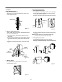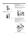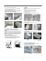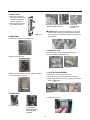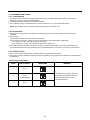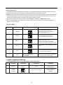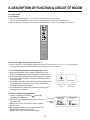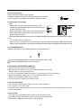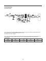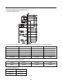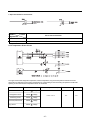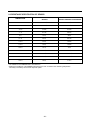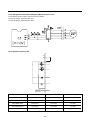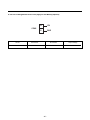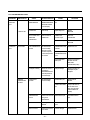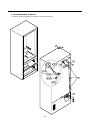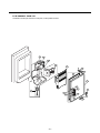
1
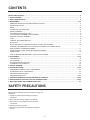
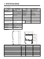
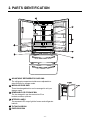
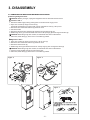
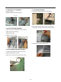
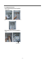
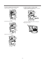
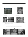
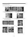
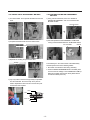
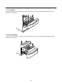
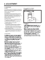
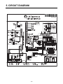
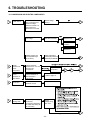
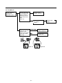
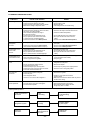
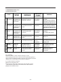
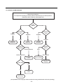
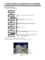
REFRIGERATOR
SERVICE MANUAL
CAUTION
BEFORE SERVICING THE UNIT,
READ THE SAFETY PRECAUTIONS IN THIS MANUAL.
MODEL: LMX21981**
LMX25981**
COLOR: STAINLESS
CONTENTS
SAFETY PRECAUTIONS ....................................................................................................................................................... 2
1. SPECIFICATIONS............................................................................................................................................................... 3
2. PARTS IDENTIFICATION ................................................................................................................................................... 4
3. DISASSEMBLY.............................................................................................................................................................. 5-14
REMOVING AND REPLACING REFRIGERATOR DOORS ...............................................................................................5
DOOR INSTALLATION ....................................................................................................................................................... 6
DOOR .............................................................................................................................................................................. 7-8
TO REMOVE THE DISPENSER .........................................................................................................................................8
DOOR ALIGNMENT ............................................................................................................................................................8
FAN AND FAN MOTOR(Evaporator) .................................................................................................................................. 8
ICE FAN SCROLL ASSEMBLY REPLACEMENT ..............................................................................................................9
DEFROST CONTROL ASSEMBLY .................................................................................................................................... 9
LAMP .................................................................................................................................................................................. 9
CONTROL BOX-REFRIGERATOR .................................................................................................................................... 9
MULTI DUCT .................................................................................................................................................................... 10
MAIN PWB, DISPLAY PWB REPLACEMENT, FUNNEL REPLACEMENT......................................................................10
SUB PWB FOR DISPENSER, DUCT DOOR REPLACEMENT, ICE CORNER DOOR
REPLACEMENT, ICE MAKER ASSEMBLY.......................................................................................................................11
AUGER MOTOR COVER, AUGER MOTOR REPLACEMENT .........................................................................................12
DOOR ICE BIN ..................................................................................................................................................................13
HOW TO REMOVE AND REINSTALL THE PULLOUT DRAWER...............................................................................14-17
4. ADJUSTMENT............................................................................................................................................................. 18-19
COMPRESSOR ................................................................................................................................................................ 18
PTC-STARTER ................................................................................................................................................................. 18
OLP(OVERLOAD PROTECTOR)......................................................................................................................................19
TO REMOVE THE COVER PTC .......................................................................................................................................19
5. CIRCUIT DIAGRAM.......................................................................................................................................................... 20
6. TROUBLESHOOTING................................................................................................................................................. 21-25
COMPRESSOR AND ELECTRIC COMPONENTS.......................................................................................................... 21
OTHER ELECTRICAL COMPONENTS ........................................................................................................................... 22
SERVICE DIAGNOSIS CHART ........................................................................................................................................ 23
REFRIGERATION CYCLE .......................................................................................................................................... 24-25
7. OPERATION PRINCIPLE & REPAIR METHOD OF ICEMAKER .............................................................................. 26-28
8. DESCRIPTION OF FUNCTION, CIRCUITS & ERROR CODES..................................................................................29-45
9. EXPLODED VIEW & REPLACEMENT PARTS LIST ..................................................................................................... 46-
SAFETY PRECAUTIONS
Please read the following instructions before servicing your
refrigerator.
1. Unplug the power before handling any elctrical
componets.
2. Check the rated current, voltage, and capacity.
3. Take caution not to get water near any electrical
components.
4. Use exact replacement parts.
5. Remove any objects from the top prior to tilting the
product.
-2-
1. SPECIFICATIONS
21 cu. ft. / 25 cu. ft.
ITEMS
ITEMS
SPECIFICATIONS
SPECIFICATIONS
DOOR DESIGN
Side Rounded
VEGETABLE TRAY
Opaque Drawer Type
DIMENSIONS (inches)
35 3/4 X 30 1/4 X 69 3/4 (WXDXH) 21cu.ft
COMPRESSOR
Recipro
35 3/4 X 34 1/4 X 69 3/4 (WXDXH) 25cu.ft
EVAPORATOR
Fin Tube Type
302.58 (21cu.ft)
CONDENSER
Wire Condenser
324.18 (25cu.ft)
REFRIGERANT
R-134a (140 g)
COOLING SYSTEM
Fan Cooling
LUBRICATING OIL
ISO10 (280 ml)
TEMPERATURE CONTROL
Micom Control
DEFROSTING DEVICE
SHEATH HEATER
NET WEIGHT (pounds)
Full Automatic
DEFROSTING SYSTEM
REFRIGERATOR
LED Module(27)
FREEZER
LED Module(9)
LAMP
Heater Defrost
DOOR FINISH
Embossed Metal, VCM, Stainless
HANDLE TYPE
Bar
INNER CASE
ABS Resin
INSULATION
Polyurethane Foam
DIMENSIONS
Description
Depth w/ Handles
Depth w/o Handles
Depth w/o Door
Depth (Total with Door Open)
Height to Top of Case
Height to Top of Door Hinge
Width
Width (door open 90 deg. w/o handle)
Width (door open 90 deg. w/ handle)
A
B
C
D
E
F
G
H
I
-3-
LMX21981**
30 in.
27 1/2 in.
23 5/8 in.
42 1/4 in.
68 3/8 in.
69 3/4 in.
35 3/4 in.
39 1/4 in.
44 1/4 in.
LMX25981**
34 1/4 in.
31 3/4 in.
27 7/8 in.
46 1 /2 in.
68 3/8 in.
69 3/4 in.
35 3/4 in.
39/1/4 in.
44 1/4 in.
2. PARTS IDENTIFICATION
4
1
2
5
6
3
4
1 ADJUSTABLE REFRIGERATOR SHELVING
The refrigerator compartment shelves are adjustable to
allow flexibility for storage needs.
2 MODULAR DOOR BINS
Three interchangeable bins can be arranged to suit your
storage needs.
3 REMOVABLE ICE STORAGE BIN
The ice storage bin can be removed to fill ice
buckets,coolers,or pitchers.
4 INTERIOR LAMPS
Two separate LED arrays light the freezer and refrigerator
interiors.
5 TILTING DOOR BIN
6 FIXED DOOR BIN
-4-
Ice Bank
Ice Door
3. DISASSEMBLY
3-1 REMOVING AND REPLACING REFRIGERATOR DOORS
● Removing
Refrigerator Door
w CAUTION: Before you begin, unplug the refrigerator. Remove food and bins from doors.
u Left Door -FIG. 2
1. Disconnect water supply tube by pushing back on the disconnect ring (4).-FIG. 1
2. Open door. Loosen top hinge cover screw (1).
Use flat tip screwdriver to pry back hooks on front underside of cover (3). Lift up cover.
3. Disconnect door switch wire harness (2). Remove cover.
4. Pull out the tube.
5. Disconnect the three wire harnesses (5). Remove the grounding screw (6).
6. Rotate hinge lever (7) counterclockwise and remove. Lift top hinge (8) free of hinge lever latch (9).
w CAUTION: When lifting hinge free of latch, be careful that door does not fall forward.
7. Place door, inside facing up, down onto a non-scratching surface.
u Right Door -FIG. 3
1. Open door. Loosen top hinge cover screw (1). Lift up cover (3).
2. Disconnect door switch wire harness (2). Remove cover.
3. Disconnect wire harness (5).
4. Rotate hinge lever (6) clockwise and remove. Lift top hinge (7) free of hinge lever latch (8).
w CAUTION: When lifting hinge free of latch, be careful that door does not fall forward.
5. Lift door up from middle hinge pin (9) and remove door.
6. Place door, inside facing up, down onto a non-scratching surface.
Figure 3
Figure 2
(2)
(1)
(2)
(1)
(4)
(5)
(6)
(3)
(5)
(4)
(3)
(6)
(7)
(8)
Figure 1
4
1) Insert the tube until you can see only one of the lines
printed on the tube.
2) After inserting, pull the tube to ascertain that it is secure.
3) Assemble clip.
Correct
-5-
Incorrect
● Door
Gasket Replacement
1. Insert gasket bracket clips
1) Insert gasket bracket edge beneath door frame edge.
2) Turn upper gasket bracket spring so that the spring
ends are in the door channel.
3) Push in clip until you hear it snap securely into place.
3-2 DOOR
● Door
Gasket Removal
1. Remove door frame cover
Starting at top of cover and working down, snap cover
out and away from door.
Frame Cover
Gasket
Bracket Clip
Handle
Spring
Door
Frame
Correct
Incorrect
Figure 1
Figure 4
2. Remove gasket bracket clips
There are two clips on each door. Start bracket removal
near one of the middle clips.
1) Pull gasket back to expose gasket bracket clip and
door frame.
2) Insert a flat tip screwdriver into seam between gasket
bracket and door frame and pry back until clips snap
out.
3) Continue prying back along seam until all clips snap
out.
Door
Frame
4) Push in remaining clip until you hear it snap securely
into place.
Note: Make sure that no part of gasket bracket edge
protrudes from beneath door frame edge.
2. Insert gasket into channel
1) Snap gasket assembly into the door bracket.
<Inserting the Gasket Assembly into the Bracket Door>
Gasket
Bracket Clip
Flat Tip
Screwdriver
Correct
Gasket
Bracket
Figure 2
3. Remove gasket
Pull gasket free from gasket channel on the three
remaining sides of door.
Incorrect
Figure 3
-6-
Figure 5
2) Press gasket into channels on the three remaining
sides of door.
3-3 DOOR ALIGNMENT
If the space between your doors is uneven, follow the
instructions below to align the doors:
1. With one hand, lift up the door you want to raise at
middle hinge.
2. With other hand, use pliers to insert snap ring as shown.
3. Insert additional snap rings until the doors are aligned.
(Three snap rings are provided with unit.)
Figure 6
3. Replace door frame cover
Starting at top of cover and working down, snap cover
back into door.
Figure 8
3-4 FAN AND FAN MOTOR(EVAPORATOR)
Figure 7
1. Remove the freezer shelf. (If your refrigerator has an
icemaker, remove the icemaker first)
2. Remove the plastic guide for slides on left side by
unscrewing phillips head screws.
3. Remove the grille by removing one screw and pulling the
grille forward.
4. Remove the Fan Motor assembly by loosening 2 screws
and disassembling the shroud.
.
FAN MOTOR
BRACKET
MOTOR
FAN
Figure 9
GRILLE
5. Pull out the fan and separate the Fan Motor and Bracket.
-7-
* Ice Fan Scroll Assembly Replacement
3-6 LAMP
Unplug Refrigerator, or disconnect power at the circuit
breaker.
If necessary, remove top shelf or shelves.
1) Remove the plastic guide for slides on left side by
unscrewing phillips head screws.
2) Pull the grille forward as shown in the second picture.
3) Disconnect wire harness of the grille
4) Remove the scroll assembly by loosening 2 screws
(1)
3-6-1 Refrigerator Compartment Lamp
1) Release 2 screws.
2) Hold both ends with your both hands and pull it
downward to remove it.
(2)
Figure 12
3) Use a flat tool as shown below to remove
the cover lamp.
(3)
(4)
3-5 DEFROST CONTROL ASSEMBLY
Defrost Control assembly consists of Defrost Sensor and
FUSE–M.
The Defrost Sensor works to defrost automatically. It is
attached to the metal side of the Evaporator and senses its
temperature. At 72°C, it turns the Defrost Heater off.
Fuse-M is a safety device for preventing over-heating of
the Heater when defrosting.
1. Pull out the grille assembly. (Figure 10)
2. Separate the connector with the Defrost Control
assembly and replace the Defrost Control assembly
after cutting the Tie Wrap. (Figure 11)
Figure 13
4) As shown below, use a flat tool to remove
the cover lamp.
Cover, Lamp
GRILLE ASSEMBLY
LED, Assembly
Case Lamp
Figure 14
DEFROST-CONTROL
ASSEMBLY
3-6-2 Freezer Compartment Lamp
1. Unplug refrigerator power cord form outlet.
2. Remove screw with direver.
3. Grasp the cover Lamp,pull the cover downward.
Figure 10
Figure 11
Figure 15
-8-
3-7 MULTI DUCT
1. Remove the upper and
lower Caps by using a flat
screwdriver, and remove
2 screws. (Figure 16)
2. Disconnect the lead wire
on the bottom position.
3) If nozzle is interfered with button , push and 4) Rmove the
pull out the bottom of button.
connected part of
Lead wire.
w CAUTION: When replacing the dispensor cover in the
reverse order of removal, be careful that the lead wire
does not come out and the water tube is not pinched by
the dispensor,
Figure 16
3-8 MAIN PWB
1) Loosen the 3 screws on the PWB cover.
3-10 DISPLAY PCB
As shown below, remove 1 case PCB fixing screw.
Remove the display PCB fixing screw.
2) Remove the PWB cover
Case, PCB
Display PCB
3-11 ICE BUTTON ASSEMBLY
3) Disconnect wire harness and replace the main PWB in
the reverse order of removal.
1) Remove the screw fixing the button lever.
2) Push the spring from the hanging hook to remove it.
3) Apply some pressure to the rib in
button in
direction.
Button Lever
3-9 DISPENSER
3-12 FUNNEL REPLACEMENT
Pull down and forward.
1) Pull out the darin
2) Hold the inner side
of cover dispenser
with both hands at the
handle side to pull it
out forward.
-9-
direction and lift the
3-13 WATER BUTTON ASSMEBLY
3-16 ICEMAKER ASSEMBLY
1) Romove screws.
1) Loosen two screws as shown in the first picture.
2) Grasp the Button assembly and lift up.
Button Lever
3-14 DUCT DOOR REPLACEMENT
2) Disconnect the wire harness & ground screw replace
theIcemaker assembly in the reverse order of removal.
1) Pull up and out on the dispenser cover to remove.
2) Disconnect the wire harness.
3) Remove the funnel
4) Replace in reverse order.
3) It separates a ground connection screw.
3-15 ICE CORNER DOOR REPLACEMENT
1) Loosen the front screw as shown in the picture.
2) Lift up the hinge with one hand.
3) Pull out the Ice Corner Door with the other hand.
hinge
- 10 -
3-17 AUGER MOTOR COVER
1) After removing the icemaker remove the (5) stainless
screws holding the auger motor cover, shown in the
picutres below.
2) Grip the bottom of motor cover assembly and pull out it.
3) Disconnect wire harness of motor cover assembly.
There is a auger motor on the back, as shown in the
picture.
Auger Motor
- 11 -
3-20 HOW TO REMOVE A DOOR ICE BIN
3-21 HOW TO INSERT A DOOR ICE BIN
1) Grip the handles, as shown in the picture.
1) Insert the Ice Bin, slightly tilting it to avoid touching the
Icemaker. (especially, ice maker lever)
1
2
2) Lift the lower part slightly.
Insert the ice bucket carefully avoid contacting the
automatic shut off arm.
3) Take the Ice Bin out slowly.
- 12 -
3-22 HOW TO REMOVE AND REINSTALL THE PULLOUT DRAWER
3-22-1 Follow Steps to Remove
Step 1) Open the freezer door.
Step 2) Remove the lower basket.
Step 3) Remove the two screws from the guide rails (one
from each side).
Step 4) Lift the freezer door up to unhook it from the rail
support and remove.
Pull both rails to full extension.
Step 5) First: Remove the gear from the left side first by releasing the tab behind the gear, place a screwdriver between the
gear and the tab and pull up on the gear.
Second: Remove the center rail.
Third: Remove the gear from the right side by following the same steps for the left side.
NOTE: THIS TAB MUST BE PUSHED IN TO RELEASE THE GEAR.
- 13 -
3-22-2 Follow Steps to Reinstall
Step 1) Reinstall the right side gear into the clip.
Step 2) Insert the rail into the right side gear. Gears do not
need to be perpendicular to each other.
Step 3) Insert the rail into the left side gear, and insert the
gear into the clip.
Step 4) The rail system will align itself by pushing the rails
all the way into the freezer section.
Pull the rails back out to full extension.
Step 5) Reinstall the freezer door by inserting the rail tabs
into the guide rail.
Step 6) Reinstall the two screws into the guide rails
(one from each side).
Step 7) Reinstall the lower basket, and close the freezer
door.
- 14 -
3-23. WATER VALVE DISASSEMBLY METHOD
3-24. FAN AND FAN MOTOR DISASSEMBLY
METHOD
1) Turn off the water. Then separate the water line from the
valve.
1) Using a short screwdriver, loosen one SCREW in
DRAIN PIPE ASSEMBLY and one connected to the
MOTOR COVER.
MOTOR COVER
→
2). Separate the Mechanical Cover and Valve Screw.
2) Pull and separate the FAN ASSEMBLY and MOTOR
turning counterclockwise based on the MOTOR SHAFT.
FAN ASSEMBLY
Mechanical Cover
MOTOR
→
3) Separate the housing and pull out the valve.
Housing
The assembly is in the reverse order of the disassembly
and take special care for the following details.
1. Be careful not to bend the tube during assembly.
2. Press the WATER DISPENSER button until water pours
out and check for leakage in the CONNECTOR TUBE (It
differs by the water pressure but usually takes about 2
minutes until water pours out.)
4) Lay a dry towel on the floor and get ready to spill water
from the water filter. Pull out the Cilp. Then press te
collet to separate the tube from the connector and pour
out the water until emptied.
Collet
Tube
Insert Line
Clip
- 15 -
3-25 TOP DRAWER
To remove the freezer drawer, pull the drawer open to full extension. Remove the lower DuraBase ®basket by lifting the
basket from the rail system.
3-26 BOTTOM DRAWER
To remove the freezer drawer, pull the drawer open to full extension. Remove the lower DuraBase ®basket by lifting the
basket from the rail system.
- 16 -
4. ADJUSTMENT
4-1 COMPRESSOR
4-1-1 Role
The compressor intakes low temperature and low pressure
gas from the evaporator of the refrigerator and compresses
this gas to high-temperature and high-pressure gas. It then
delivers the gas to the condenser.
4-2-3
-Applied circuit diagram
method for the motor
● Starting
ELECTRICAL AND DIMENSION DIAGRAM
ELECTRICAL CONNECTION DIAGRAM
the thermostat is opened, obstructing the proper functioning
of the TSD. It is vital f
or the TSD circuit and compressor t
o
remain completely de-energized after opening the
thermostat.
Ð Use of the fixing clamp is essential, as this prevents
disconnection or bad TSD contact in relation to the
compressor as well as to running capacitor in relation to the
TSD. The ones that assemble it have to guarantee a
perfect connection between the parts. Bad contacts and
sparking can burn out the electronic circuit.
Ð The electronic circuit was designed taking the mandatory
use of the running capacitor into consideration.
The 1 15V version is rect
angular box, assembling directly
TSD body .
Ð The plastic box was projected to offer protection against
TSD's
mechanical
system
internal
shock
production
components
normally
present
in
lines.
may
undergo
degradation
when in contact with chemical elements such as CI2 , H2 S,
NH , SO
3
release
X
, NO
X
. Some plastic isolation of cables may
chemical
elements
when
submitted
to
high
temperature conditions. Thus, check if the isolation of the
cables used on the terminal board are in accordance with
this
STA
R
IN
can maintain a residual voltage over the compressor when
Ð The
TSD
N
4-2-4
Ð
The TSD was designed for the operation with a run
capacitor
and
Embraco
domestic
compressor;
any
other
application must be previously evaluated by EmbracoÕs
technical
Ð
team.
Embraco reserves the right to check the customer's
handling
of
indicating
Ð
the
manufacturing
possible
After
replacement,
must
have
proper
/
adjustments
the
assembly
should
compressor
processing,
and
and
the
process,
any
itÕs
be
required.
accessories
components
must
recommendation.
recomendations
are
intended
to
minimize
the
adverse impacts that may be caused to the environment.
parallel to the thermostat. Systems with this configuration
and
C
L
These
defrosting electrical resistance or any other component in
refrigeration
M
non-ferrous, polymers, oils, ...) directives.
Ð The TSD must not be applied to refrigeration systems with
contamination
S
be recycled according to the material group (ferrous,
4-2 TSD STARTER
onto the
MA
4-1-3 Note for usage
(1) Be careful not to allow over-voltage and over-current.
(2) If compressor is dropped or handled carelessly, poor
operation and noise may result.
(3) Use proper electric components appropriate to the
particular compressor in your product.
(4) Keep compressor dry.
If the compressor gets wet (in the rain or a damp
environment) and rust forms in the pin of the Hermetic
Terminal, poor operation and contact may result.
If the hermetic connector rusts out or fails, refrigerant
and oil will be expelled into the contact area, probably
resulting in smoke and fire.
(5) When replacing the compressor, be careful that dust,
humidity, and soldering flux don’t contaminate the inside
of the compressor. Contamination in the cylinder may
cause noise, improper operation or even cause it to
lock up.
T
4-1-2 Composition
The compressor includes overload protection. The PTC
starter and OLP (overload protector) are attached to the
outside of the compressor. Since the compressor is
manufactured to tolerances of 1 micron and is hermetically
sealed in a dust and moisture-free environment, use
extreme caution when repairing it.
4-3 OLP (OVERLOAD PROTECTOR)
4-3-1 Definition of OLP
(1) OLP (OVERLOAD PROTECTOR) is attached to the
Compressor and protects the Motor by opening the
circuit to the Motor if the temperature rises and
activating the bimetal spring in the OLP.
(2) When high current flows to the Compressor motor, the
Bimetal works by heating the heater inside the OLP,
and the OLP protects the Motor by cutting off the
current flowing to the Compressor Motor.
4-3-2 Role of the OLP
(1) The OLP is attached to the Sealed Compressor used
for the Refrigerator. It prevents the Motor Coil from
being started in the Compressor.
(2) For normal operation of the OLP, do not turn the Adjust
Screw of the OLP in any way.
(OVERLOAD PROTECTOR cross section)
12345678
330 FBYY
Electrical
characteristics
part number
-S1 BOX98
Customer part
number
Lot code/
date code
Physical
termination
part number
Part
No.
Name
Base, phenolic
(UL 94 V-0 rated)
Movable arm support, plated steel
Stationary contact support,
plated steel
Heater support, plated steel
Heater, resistance alloy
Disc, thermostatic alloy
Movable arm, spring temper
copper alloy
Contact, movable, silver on copper
Contact, stationary, silver on copper
Slug, plated steel
Cover, polyester
(UL 94 V -0 rated)
Pin connector, plated copper alloy
(To engage 2.33/2.66 mm dia. pin)
Quick-connect terminal, brass,
conforms to UL 310, MEMA
DC-2, DIN 46344
Figure 19
- 18 -
5. CIRCUIT DIAGRAM
- 19 -
6. TROUBLESHOOTING
6-1 COMPRESSOR AND ELECTRIC COMPONENTS
1
Power source.
Remove TSD-Starter
from compressor and
measure voltage
between terminal C of
compressor and
terminal 5 or 6 of TSD.
(Rated voltage
±10%)?
No voltage.
OLP disconnected?
YES
2
YES
NO
Replace OLP.
5
Check connection
condition.
Reconnect.
Applied voltage isn't
in acceptable range.
(115V ±10%)
Check
resistance of
motor
compressor.
Check resistance
between M-C, S-C and
M-S in motor
compressor.
3
Check
resistance of
TSD-Starter.
Check resistance of
two terminals in
TSD-Starter.
4
Check OLP.
Check resistance of two
terminals in OLP.
5
Check
starting state.
2
Check the power supply
under load.
(Compressor attempting
to re-start after being off
for 5 minutes).
Advise customer that
power supply needs to be
checked by an electrician.
5
The range of resistance is between 1~50½ (ok)
Open or short
Replace
compressor.
3
4
3
5
Refer to page 12.
Supply
voltage rating
with ±10%.
NO
- 20 -
1
6-2 TSD AND OLP
Normal operation of
compressor is
impossible or poor.
Separate TSD-Starter
from compressor and
measure resistance
between No. 5 and 6
of PTC-Starter with a
tester.
(Figure 19)
Observation value is
115V/60Hz : 6.8Ω±30%
The resistance value
is 0Ω (short) or
∞ (open).
Shows continuity
Separate OLP from
compressor and check
resistance value
between two terminals
of OLP with a tester.
(Figure 20)
Open
Check another
electric component.
Replace OLP.
RoHS
EECON JLLE
TSD- 115/127V
R
- 60Hz - Y
513604000
17/JUL
/06
01112
000000007Z
1234567891
Figure 19
- 21 -
Figure 20
Replace TSDStarter.
6-3 SERVICE DIAGNOSIS CHART
COMPLAINT
POINTS TO BE CHECKED
REMEDY
No Cooling.
• Is the power cord unplugged from the outlet?
• Check if the power switch is set to OFF.
• Check if the fuse of the power switch is shorted.
• Measure the voltage of the power outlet.
• Plug into the outlet.
• Set the switch to ON.
• Replace the fuse.
• If the voltage is low, correct the wiring.
Cools poorly.
• Check if the unit is placed too close to the wall.
• Check if the unit is placed too close to the stove,
gas cooker, or in direct sunlight.
• Is the ambient temperature too high or
the room door closed?
• Check if food put in the refrigerator is hot.
• Did you open the door of the unit too often
or check if the door is sealed properly?
• Check if the Control is set to Warm position.
• Place the unit about 4 inches (10 cm) from the wall.
• Place the unit away from these heat sources.
Food in the
Refrigerator
is frozen.
• Is food placed in the cooling air outlet?
• Check if the control is set to colder position.
• Is the ambient temperature below 41°F(5°C)?
• Place foods in the high-temperature section.
(front part)
• Set the control to Recommended position.
• Set the control to Warm position.
Condensation or ice
forms inside
the unit.
• Is liquid food sealed?
• Check if food put in the refrigerator is hot.
• Did you open the door of the unit too
often or check if the door is sealed properly?
• Seal liquid foods with wrap.
• Put in foods after they have cooled down.
• Don't open the door too often and close
it firmly.
Condensation forms
in the Exterior Case.
• Check if the ambient temperature and humidity
of the surrounding air are high.
• Is there a gap in the door gasket?
• Wipe moisture with a dry cloth. It will disappear
in low temperature and humidity.
• Fill up the gap.
There is abnormal
noise.
• Is the unit positioned in a firm and even place?
• Adjust the Leveling Screw, and position the
refrigerator in a firm place.
• Remove the objects.
• Are any unnecessary objects placed
in the back side of the unit?
• Check if the Drip Tray is not firmly fixed.
• Check if the cover of the compressor enclosure
in the lower front side is taken out.
Door does not
close well.
• Check if the door gasket is dirty with
an item like juice.
• Is the refrigerator level?
●
• Put in foods after they have cooled down.
• Don't open the door too often and close
it firmly.
• Set the control to Recommended position.
• Fix the Drip Tray firmly in the original position.
• Place the cover in its original position.
• Clean the door gasket.
• Is there too much food in the refrigerator?
Ice and foods
smell unpleasant.
• Lower the ambient temperature.
• Check if the inside of the unit is dirty.
• Are foods with a strong odor unwrapped?
• The unit smells of plastic.
• Position in a firm place and level the
Leveling Screw.
• Make sure food stored in shelves does not prevent
the door from closing.
• Clean the inside of the unit.
• Wrap foods that have a strong odor.
• New products smell of plastic, but this
will go away after 1-2 weeks.
Other possible problems:
Check if frost forms in
the freezer.
Not
defrosting
Check Components
of the defrosting
circuit.
Check the
refrigeration system.
The system
is faulty.
Perform sealed
system repair.
Check the
Thermistor.
The operation of
the Thermistor is
incorrect.
- 22 -
Replace the
Thermistor.
6-4 REFRIGERATION CYCLE
▼ Troubleshooting Chart
CAUSE
STATE OF
THE UNIT
STATE OF THE
EVAPORATOR
TEMPERATURE
OF THE
COMPRESSOR
REMARKS
LEAKAGE
CLOGGED BY DUST
PARTIAL
LEAKAGE
Freezer
compartment and
Refrigerator don't
cool normally.
Low flowing sound of
Refrigerant is heard and
frost forms in inlet only.
A little higher
than ambient
temperature.
• Refrigerant level is low due
• to a leak.
• Normal cooling is possible by
• restoring the normal amount of
• refrigerant and repairing the leak.
COMPLETE
LEAKAGE
Freezer
compartment and
Refrigerator don't
cool normally.
Flowing sound of refrigerant
is not heard and frost isn't
formed.
Equal to ambient
temperature.
• No discharging of Refrigerant.
• Normal cooling is possible by
• restoring the normal amount of
• refrigerant and repairing the leak.
PARTIAL
CLOG
Freezer
compartment and
Refrigerator don't
cool normally.
Flowing sound of refrigerant
is heard and frost forms
in inlet only.
A little higher
than ambient
temperature.
• Normal discharging of the
• refrigerant.
• The capillary tube is faulty.
WHOLE
CLOG
Freezer
Flowing sound of refrigerant
compartment and
is not heard and frost isn't
Refrigerator don't cool. formed.
Equal to ambient
temperature.
• Normal discharging of the
• Refrigerant.
Cooling operation
stops periodically.
Flowing sound of refrigerant
is not heard and frost melts.
Lower than
ambient
temperature.
• Cooling operation restarts
• when heating the inlet of the
• capillary tube.
COMPRESSION
Freezer and
Refrigerator
don't cool.
Low flowing sound of
refrigerant is heard and
frost forms in inlet only.
A little higher
than ambient
temperature.
• Low pressure at high side
• of compressor due to low
• refrigerant level.
NO COMPRESSION
No compressing
operation.
Flowing sound of refrigerant
is not heard and there is
no frost.
Equal to ambient
temperature.
• No pressure in the high
• pressure part of the
• compressor.
MOISTURE
CLOG
DEFECTIVE
COMPRESSION
6-4-1 Cleaning
There is no need for routine condenser cleaning in normal
Home operating environments. If the environment is particularly greasy or
dusty, or there is significant pet traffic in the home, the condenser should be
cleaned every 2 to 3 months to ensure maximum efficiency.
If you need to clean the condenser:
● Remove the mechanical cover.
● Use a vacuum cleaner with a soft brush to clean the grille, the open
areas behind the grille and the front surface area of the condenser.
● Replace the mechanical cover.
- 23 -
6-4-2 SEALED SYSTEM DIAGNOSIS
“Not Cooling” Complaint
All components operating, No airflow problems, Not frosted up as a defrost problem
problem has been isolated to sealed system area
Frost
Pattern?
Partial
None
Equalization
Test
Equalization
Test
Very Fast
Very Slow
Very Slow
Very Fast
Fast
Inefficient
Compressor
Partial
Restriction
Complete
Restriction
Condenser
Temperature
Cap Tube
Sound
Hotter than Normal
Faint
Room Temperature
None to Weak
Air/Low Side
Leak
Loss of Change
Compressor Not
Pumping
Trace of Oil
Yes
No
Leak
Undercharge
(The equalization test is trying to restart a compressor using a start kit after it has been operating.)
- 24 -
7. OPERATION PRINCIPLE AND REPAIR METHOD OF ICEMAKER
7-1 OPERATION PRINCIPLE
7-1-1 Operation Principle of IceMaker
Power On
Start Position
Icemaking
Mode
Harvest
Mode
• Adjusts EJECTOR to Start Position with power on.
• Waits until water becomes ICE after starting the
icemaking operation.
• Runs MOTOR to drop ice from the tray into the ICE BIN.
(During harvest mode, check if the ice bin is full)
Park Position
Fill
• Reaches Start Position
• Performs Ice Making Mode after supplying water by operating
the SOLENOID in ICE VALVE.
Test Mode
• To operate LINE and SERVICE, press and hold the Fill Key
for 3 seconds. The icemaker will run through 3 stages:
Harvest
Fill
Icemaking.
1. Turning the Icemaker stop switch off (O) stops the ice making function.
2. Setting the Icemaker switch to OFF and then turning it back on will reset the icemaker control.
EJECTOR
Cube Size
Indicator Light
Cube Size
Selection Button
- 25 -
Power
Switch
Automatic
Shut off Arm
7-2 ICE MAKER FUNCTIONS
7-2-1. Icemaking Mode
1. Icemaking refers to the freezing of supplied water in the ice tray. Complete freezing is assured by measuring the
temperature of the Tray with Icemaking SENSOR.
2. Icemaking starts after completion of the water fill operation.
3. The Ice Making function is completed when the sensor reaches 19°F (-7°C), 55 minutes after starting.
NOTE : After Icemaker Power is ON, the Icemaker heater will be on for test for 6 sec.
7-2-2. Harvest Mode
1. Harvest (Ice removing) refers to the operation of dropping ices into the ice bin from the tray when icemaking has
completed.
2. Harvest mode:
(1) The Heater is ON for 30 seconds, then the motor starts.
(2) The feeler arm senses the quantity of ice in the ice storage bin while rotating with the EJECTOR.
A. Ice storage bin is full : The EJECTOR stops (heater off).
B. Ice storage bin is not full : The EJECTOR rotates twice to open for ice.
If the EJECTOR does not rotate once within 5 minutes in B mode, separate heater control mode starts operating to
prevent the EJECTOR from being constrained. (It is recommended that the user open for ice to return to normal mode.)
7-2-3. Fill/Park Position
1. Once a normal harvest mode has been completed, the water solenoid will be activated.
2. The amount of water is adjusted by pressing the Fill Key repeatedly. This changes the time allowed for fill as illustrated in
the table below.
Water supply amount TABLE
STAGE
TIME TO SUPPLY
1
5 sec.
INDICATIONS
REMARKS
The water amount will vary depending
2
on the water control Switch setting, as
5.5 sec.
well as the water pressure of the
(FIRST STAGE)
connected water line.
3
6 sec.
- 26 -
7-2-4 Function TEST
1. This is a forced operation for TEST, Service, cleaning, etc. It is operated by pressing and holding the Fill Key for 3 seconds.
2. The test works only in the Icemaking Mode. It cannot be entered from the Harvest or Fill mode.
3. Caution! If the test is performed before water in the icemaker is frozen, the ejector will pass through the water. When the
Fill mode begins (Stage 4), unless the water supply has been shut off, added water will overflow into the ice bin. If the
control doesn’t operate normally in the TEST mode, check and repair as needed.
4. After water is supplied, the normal CYCLE is followed: icemaking → Harvest → Park Position → Fill.
5. Five seconds after Stage 5 is completed, the Ice Maker returns to MICOM control. The time needed to supply water
resets to the pre- test setting.
Diagnosis TABLE
STAGE
ITEMS
INDICATOR
REMARKS
1
HEATER
Five seconds after heater starts, a
heater will go off if the temperature by
sensor is higher than 10°C
2
MOTOR
Five seconds after heater starts, you
can confirm that a motor is moving.
3
HALL IC I
Check if Ice Bin is full or not.
If Ice bin is full, the motor and heater
are off and on stand by until Ice bin is empty.
4
HALL IC II
You can confirm HALL IC detection of start
position.
5
VALVE
6
Reset
Two seconds after detection of start position,
you can confirm that valve is on.
Five seconds after fifth stage is completed,
The icemaker resets to initial status.
Return to Status prior to
TEST MODE
7-3 DEFECT DIAGNOSIS FUNCTION
7-3-1 ERROR CODES shown on Ice Maker water supply control panel
NO
DIVISION
1
Normal
2
Icemaking
Sensor
malfunction
INDICATOR
CONTENTS
REMARKS
None
Display switch
operates properly
Open or short-circuited wire
Make sure that the wire
on each sensor is
connected.
Mark time to
supply
- 27 -
8. DESCRIPTION OF FUNCTION & CIRCUIT OF MICOM
8-1 FUNCTION
8-1-1 Function
1. When the appliance is plugged in, it is set to 37°F for Refrigerator and 0°F for freezer.
You can adjust the Refrigerator and the Freezer control temperature by pressing the ADJUST button.
2. When the power is initially applied or restored after a power failure, it is set to Control temperature Previously.
ICE TYPE
ICE TYPE
FREEZER
REFRIGERATOR
ICE PLUS
LIGHT / FILTER
ALARM / LOCK 3SECS
8-1-2 How to Toggle the Display between °F & °C
1. The initial setting is °F and the display temperature mode can be changed from °F to °C or °C to °F by pressing and
holding the FRZ TEMP and the REF TEMP keys at the same time for over 5 seconds.
8-1-3 Lock function (dispenser and display button lock)
1. When the refrigerator is first turned on, the buttons are not
locked. The display panel shows the padlock unlocked icon.
2. To lock the display, the dispenser, and the control panel, press
and hold the LOCK button for 3 seconds. The locked pad lock
icon is displayed.
3. The LOCK button is the only control feature that remains active
in the locked state. The buzzer sound, other control buttons,
and the dispenser are deactivated.
4. To release from the locked state, press and hold the LOCK
button again for 3 seconds.
8-1-4 Filter condition display function
1. There is a replacement indicator
for the filter
cartridge on the dispenser.
2. Water filter needs replacement once six months or of
using water filter.
3. Water Filter icon turn on to tell you need to replace
the filter soon.
4. After replacing the filter, press and hold the FILTER
RESET button more than 3 seconds.
HOLD 3 SECS icon turn off with reset status.
Classification
- 28 -
Filter Status
Display
Press & Hold
Ex) In selecting
"LOCK"
In initial Power On
/ Filter RESET
Press & Hold
Ex) In selecting
"LOCK" again
Replace indicator
light on
8-1-5 Ice Plus selection
Please select this function for quick freezing.
• Function is repeat Ice Plus Icon whenever pressing Ice Plus button.
• Ice Plus function automatically turns off after a fixed time passes.
8-1-6 Dispenser use selection
1. Water
ACTIVE WATER BUTTON
* Water switch: Hold your cup in the dispenser for a few
ICE TYPE
WATER SWITCH
seconds with pressing water switch to allow the last drops
ICE SWITCH
of water to fall into the cup.
* Active water button: Place big bowl on the dispenser bottom
with pressing active water button to allow the last drop of
water to fall into the bowl.
* When after initially establ ishing the water comes out, the water tank inside fills and until at the time of quality the hour is caught.
2. Ice
* You can select cube or crushed ice.
* Select cube ice or crushed ice by cycling through the selections when pressing the CUBE/ CRUSH button.
* Hold your cup in the dispenser for a few seconds with pressing ice switch to allow the last pieces of ice to fall into the cup.
PUSH
8-1-7 DISPENSER LIGHT
-Whenever pressed the LIGHT button, DISPLAY is changed as belows.
Normal status: When dispenser is operated, DISPENSER LIGHT is ON.
ON status: DISPENSER LIGHT is on continuously.
8-1-8 CONTROL OF FREEZER FAN MOTOR
1. Freezer fan motor has high and standard speeds.
2. High speed is used at power-up, for Ice Plus, and when refrigerator is overloaded.
Standard speeds is used for general purposes.
3. To improve cooling speed, the RPM of the freezer fan motor change from normal speed to high.
4. High speed (2700RPM) : Initial power on or load corresponding operation, Ice Plus
Normal speed (2400RPM) : General working conditions.
5. Fan motor stops when refrigerator or freezer door opens.
8-1-9 Cooling Fan Motor
1. The cooling fan is switched ON and OFF in conjunction with the compressor.
2. The cooling fan runs at a single speed.
3. The Failure sensing mathod is the same as in the fan motor of the freezing fan motor(refer to failure diagnosis function
table for failure display).
8-1-10 Icing Fan
The Icing Fan is controlled by the the sensor on the top of the ice room.
The Failure sensing mathod is the same as in the fan motor of the freezer
(refer to failure diagnosis function table for failure display)
- 29 -
8-1-11 Ice Plus
1. The purpose of this function is to intensify the cooling speed of freezer and to increase the amount of ice.
2. Whenever selection switch is pressed, selection/release, the Icon will turn ON or OFF.
3. If there is a power outage and the refrigerator is powered on again, Ice Plus will be canceled.
4. To activate this function, press the Ice Plus key and the Icon will turn ON. This function will remain activated for 24 hrs.
The first three hours the compressor and Freezer Fan will be ON. The next 21 hours the freezer will be controlled at the
lowest temperature. After 24 hours or if the Ice Plus key is pressed again, the freezer will return to its previous
temperature.
5. During the first 3 hours:
(1) Compressor and freezer fan (HIGH RPM) run continuously.
(2) If a defrost cycle begins during the first 90 minutes of Ice Plus, the Ice Plus cycle will complete its cycle after
defrosting has ended.
If the defrost cycle begins when Ice Plus has run for more than 90 minutes, Ice Plus will run for two hours after the
defrost is completed.
(3) If Ice Plus is pressed during defrost, Ice Plus Icon is on but this function will start seven minutes after defrost is
completed and it shall operate for three hours.
(4) If Ice Plus is selected within seven minutes after compressor has stopped, the compressor (compressor delays seven
minutes) shall start after the balance of the delay time.
(5) The fan motor in the freezer compartment runs at high speed during Ice Plus.
6. For the rest of the 21 hours, the freezer will be controlled at the lowest temperature.
8-1-12 Alarm for Open Door
1. This feature sounds a buzzer when the freezer or refrigerator door is not closed within 1 minute after it is opened.
2. One minute after the door is opened, the buzzer sounds three times each for 1/2 seconds. These tones repeat every 30
seconds.
3. The alarm is cancelled when the freezer or the refrigerator is closed while the buzzer sounds.
Freezer Door Closed
or Refrigerator
Door
Open
Closed
Open
Closed
3 Times
3 Times
3 Times
3 Times
Buzzer
Within 1 min.
1 min.
- 30 -
30 sec
30 sec
30 sec
8-1-13 Defrosting (removing frost)
1. Defrosting starts each time the COMPRESSOR running time reaches 7~50 hours.
2. For initial power on or for restoring power, defrosting starts when the compressor running time reaches 4 hours.
3. Defrosting stops if the sensor temperature reaches 46°F(8°C) or more. If the sensor doesn’t reach 46°F(8°C) in
1 hours, the defrost mode is malfunctioning. (Refer to the defect diagnosis function, 8-1-14.)
4. Defrosting won’t function if its sensor is defective (wires are cut or short circuited)
8-1-14 Defect Diagnosis Function
1. Automatic diagnosis makes servicing the refrigerator easy.
2. When a defect occurs, the buttons will not operate.
3. When the defect CODE removes the sign, it returns to normal operation (RESET).
4. The defect CODE shows on the Refrigerator and Freezer Display.
ICE TYPE
✽ LED check function: If simultaneously pressing Ice Plus button and freezing temperature adjustment button
for a second, display LED graphics on. If releasing the button, the LED graphic displays
the previous status.
- 31 -
ERROR CODE on display panel
Error Display
NO
1
Error Detection
Category
Freezer
Temperature
Ref.
Temperature
Normality
Error Generation Factors
None
2
Freezer Sensor
Error
Er
FS
Short or Disconnection
of Freezer Sensor
3
Refrigerator
Sensor Error
Er
rS
Short or Disconnection
of Refrigerator Sensor
4
Defrosting
Sensor Error
Er
dS
Short or Disconnection
of Defrosting Sensor
5
Icing Sensor
Error
Er
IS
Short or Disconnection
of Icing Sensor
6
Poor Defrosting
7
Abnormality of
BLDC FAN Motor
for Ice Making
8
Abnormality of
BLDC FAN Motor
for Freezer
9
Abnormality of
BLDC FAN Motor
for Mechanic Room
10
Communication
Error
Er
Er
Er
Er
Er
Remark
Normal operation of
Display
Each Sensor have to check
disconnection
dH
Even though it is passed
1 hour since then
Defrosting , if Defrosting
sensor is not over
46°F(8°C), it is caused
Temperature Fuse
Disconnection,Heater
disconnection, DRAIN Jam,
Poor Relay for Heater
IF
It is caused when F/B
signal isn’t over 65
seconds during BLDC
FAN motor operating
Poor BLDC Motor
connection, DRIVE IC, and
TR
FF
It is caused when F/B
signal isn’t over
65seconds during BLDC
FAN motor operating
Poor BLDC Motor
connection, DRIVE IC, and
TR
CF
It is caused when F/B
signal isn’t over
65seconds during BLDC
FAN motor operating
Poor BLDC Motor
connection, DRIVE IC, and
TR
CO
Communication Error
between Micom of Main
PCB and Display Micom
Poor Communication
connection,Poor TR of
Transmitter and Receiver
NOTE) In the case of Room Temperature Seneor Error, “Er rt” appears on the Display when ICE PLUS KEY
and Freezer Temp’ KEY pressed at the same time for one second.
- 32 -
8-1-16 TEST Mode
1. The Test mode allows checking the PCB and the function of the product as well as finding out the defective part in case of
an error.
2. The test mode is operated by pressing test button at main PCB controller.
3. While in the test mode, the function control button is not recognized, but the recognition tone sounds.
4. After exiting the test mode, be sure to reset by unplugging and then plugging in the appliance.
5. If an error, such as a sensor failure, is detected while in the test mode, the test mode is cleared and the error code is
displayed.
6. While an error code is displayed, the test mode will not be activated.
Table 1. Function Test
MODE
OPERATION
TEST3
REMARKS
Push test button one time
at main PCB controller.
1) peration of the COMPRESSOR
and FAN(Freezer/Condenser/Icing)
2) Stepping DAMPER OPEN
3) Defrosting HEATER OFF
4) DISPLAY LED all ON
Push Test button one in
TEST PCB MODE1.
1) peration of the COMPRESSOR
and FAN(Freezer/Condenser/Icing)
2) Stepping DAMPER CLOSE
3) Defrosting HEATER OFF
4) DISPLAY LED shows ‘’22’’
Push Test button one in
TEST PCB MODE2.
1) The COMPRESSOR and the
FAN(Freezer/Condenser/Icing) OFF
2) Stepping DAMPER CLOSE
3) Defrosting HEATER ON
4) DISPLAY LED shows “33”
Reset if the
Temperature of the
Defrosting Sensor is
46˚F(8˚C)or more.
Reset to the previously setting
Before TEST MODE.
The compressor will
Start after a 7-minute
Delay.
TEST1
TEST2
FUNCTION
Push Test button one in
TEST PCB MODE3 .
RESET
- 33 -
8-2 PCB FUNCTION
8-2-1 Power Circuit
The secondary part of the TRANSFORMER is composed of the power supply for the display, the BLDC FAN Motor drive
(15.5 V), the relay drive (12 Vdc) and the MICOM and IC (5 Vdc).
The voltage for each part is as follows:
VA1 is a part for preventing over voltage and noise. When 230V or higher power is applied, the inside elements are shortcircuited and broken, resulting in blowout of the fuse in order to protect the elements of the secondary part of the
TRANSFORMER.
PART
VA 1
CE 3
CE 4
CE 5
VOLTAGE
115 Vac
12 Vdc
15.5 Vdc
5V
- 34 -
8-2-2 Load / Fan & Open Door Detection Circuit
1. Load Drive Condition Check
To measure outputs of the control board, check voltages between the pins for the following components:
Circuit
Pin Number
Pin Number
Output Voltage
I/Maker Pilot Valve
Con3 Pin3
Con3 Pin2
115 VAC
R/R Door, R/L Door Heater
Con3 Pin8
Con3 Pin2
115 VAC
Def Heater
Con3 Pin10
Con3 Pin2
115 VAC
Water Pilot Valve
Con3 Pin11
Con3 Pin2
115 VAC
Compressor
Con3 Pin12
Con3 Pin2
115 VAC
2-1. APPLY For AC Lamp Model(Optional)
LAMP-R
Con3 Pin9
Con3 Pin2
115 VAC
LAMP-F
Con3 Pin7
Con3 Pin2
115 VAC
2-2. Freezing compartment fan
Pin2 & 3 of con4
MOTOR OFF
2V or less
MOTOR ON
13V~15V
- 35 -
2-3. Machine compartment fan
Pin8 & 9 of con4
MOTOR OFF
2V or less
MOTOR ON
10V~14V
2-4. Icing compartment fan
Pin5 & 6 of con4
MOTOR OFF
2V or less
MOTOR ON
10V~14V
- 36 -
3. Open Door Detection Circuit Check
Measurement
Location
Freezer/
Refrigerator Door
Pin 11 & 12 of con4 Ref.Door
Pin 5 & 6 of con6 Fre.Door
Closed
5V
Open
0V
8-2-3 Temperature Sensor Circuit
The upper circuit reads refrigerator temperature, freezer temperature, Icing sensor temperature and defrost sensor
temperature for defrosting and the indoor temperature for compensating for the surrounding temperature into MICOM.
Opening or short state of each temperature sensor are as follows:
SENSOR
CHECK POINT
Freezer sensor
POINT A Voltage
Refrigerator sensor
POINT B Voltage
Defrosting sensor
POINT C Voltage
Room Temperature sensor
POINT D Voltage
Icing sensor
POINT E Voltage
NORMAL (-30°C ~ 50°C)
0.5 V ~ 4.5 V
- 37 -
SHORT-CIRCUITED
0V
OPEN
5V
8-3 RESISTANCE SPECIFICATION OF SENSOR
TEMPERATURE
RESISTANCE OF FREEZER/ICING
SENSOR
RESISTANCE OF REFRIGERATOR &
DEFROST SENSOR & ROOM SENSOR
- 20 ˚C
22.3 KΩ
77 KΩ
- 15 ˚C
16.9 KΩ
60 KΩ
- 10 ˚C
13.0 KΩ
47.3 KΩ
- 5 ˚C
10.1 KΩ
38.4 KΩ
0 ˚C
7.8 KΩ
30 KΩ
+ 5 ˚C
6.2 KΩ
24.1 KΩ
+ 10 ˚C
4.9 KΩ
19.5 KΩ
+ 15 ˚C
3.9 KΩ
15.9 KΩ
+ 20 ˚C
3.1 KΩ
13 KΩ
+ 25 ˚C
2.5 KΩ
11 KΩ
+ 30 ˚C
2.0 KΩ
8.9 KΩ
+ 40 ˚C
1.4 KΩ
6.2 KΩ
+ 50 ˚C
0.8 KΩ
4.3 KΩ
• The resistance of the SENSOR has a ±5% tolerance.
• Measure the resistance of the SENSOR after leaving it for over 3 minutes in the measuring temperature.
This delay is necessary due to sensor response speed.
• Measure the F-SENSOR, SUPER FROST SENSOR, R1, R2-SENSOR after disconnect CON5 of PWB ASSY, MAIN.
- 38 -
8-2-4 Refrigeration Compartment Stepping Motor Damper Circuit
A reversible DC motor is used to open and close the damper.
To open the damper, push test button once.
To close the damper, push test button twice.
8-2-5 Dispenser Drive Circuit
Circuit
Pin Number
Pin Number
Output Voltage
Auger Motor
Con1 Pin12
Con1 Pin4
115 VAC
Solenoid Cube
Con1 Pin11
Con1 Pin4
115 VAC
Pilot/ Water Valve
Con1 Pin10
Con1 Pin4
115 VAC
Solenoid Dispenser
Con1 Pin9
Con1 Pin4
115 VAC
Heater
Con1 Pin7
Con1 Pin4
115 VAC
- 39 -
8-2-6 LED in Refrigerator/Freezer room (Apply for LED Model) (Optional)
14
12V
15
GND
CON6
Circuit
Pin Number
Pin Number
Output Voltage
LED Module
Con6 Pin14
Con6 Pin15
12 VDC
- 40 -
8-3 TROUBLESHOOTING
PROBLEM
INDICATED BY
POWER
SOURCE is
poor.
1. The whole
CHECK
CHECKING METHOD
CAUSE
1. FREEZER/
REFRIGERATOR.
Check if
FREEZER/REFRIGERA
TOR DOOR IS OPEN
and check display.
POWER SOURCE is
poor.
Replace Main PWB
2. If LAMP is dim.
Check visually.
Applied voltage error.
Replace
Main PWB
3. The connection of the
MAIN PWB
CONNECTOR.
Check connection of
CONNECTOR.
CONNECTOR
connection is poor.
Reconnect
CONNECTOR
TRANS FUSE is open.
Replace
Main PWB
COMPRESSOR locked
or blocked.
Replace OLP, PTC.
OLP, PTC is poor.
COMPRESSOR RELAY
is poor.
Replace MAIN PWB.
THE CONNECTING
WIRE is poor.
Check the connection of
the black wire of the
MAIN PWB
CONNECTOR (CON3).
2. DISPLAY LED
COOLING is
poor.
NO COOLING.
FREEZER
TEMPERATURE
is incorrect
SOLUTION
1. If the COMPRESSOR
operate.
USE TEST MODE1
(forced COOLING).
If less than 7 minutes
pass after compressor
shuts off, don’t press the
KEY and wait.
2. If refrigerant is leaking.
Measure the amount of
frost sticking on
EVAPORATOR and the
surface temperature of
the condenser pipe.
Refrigerant leakage.
Replace the leaking part
and replace any lost
refrigerant.
1. If FAN MOTOR
operates.
USE TEST MODE1
(forced COOLING).
FAN MOTOR is poor.
Replace the FAN
MOTOR.
CONNECTING WIRE is
poor.
Certify the MOTOR and
the connection of the
black wire of the MAIN
PWB CONNECTOR
(CON4).
See DEFROSTING is
poor.
2. If DEFROSTING is
normal.
Check the amount of frost DEFROSTING is poor.
sticking on the
EVAPORATOR .
3. If SENSOR is normal.
of the Refrigerator
SENSOR.
SENSOR RESISTANCE
is poor.
Replace SENSOR.
4. Door Line contact.
Check the seal when the
door is closed.
Door liner damaged.
Replace door liner.
- 41 -
PROBLEM
INDICATED BY
COOLING is
poor.
If
REFRIGERATOR
TEMPERATURE
is too low.
DEFROSTIN
G is poor.
NO
DEFROSTING.
CHECK
CHECKING METHOD
CAUSE
SOLUTION
Make sure the DOOR
isattached.
1. If FREEZER
TEMPERATURE is
normal.
Check is FREEZER
TEMPERATURE is too
low.
2. If amount of cool air
from FAN MOTOR is
sufficient.
Make sure that the
amount and speed of cool
air are sufficient by
touching the check
supplied on the
REFRIGERATOR.
FAN MOTOR is poor.
Replace FAN MOTOR.
Passage of cool air is
blocked.
Remove impurities.
EVA frozen.
See DEFROSTING is
poor.
3. Door Line contact.
Check door seal when
door is closed.
Door liner damaged.
Replace Door liner.
1. If HEATER emits heat.
USE TEST MODE3
(forced DEFROSTING).
HEATER disconnection.
Replace HEATER.
TEMPERATURE FUSE
disconnection.
Replace
TEMPERATURE FUSE.
Connection is poor.
Check EVAPORATOR
connection and wire of
MAIN PWB
CONNECTOR.
DEFROST-SENSOR is
poor.
Replace DEFROSTSENSOR.
HEATER RELAY is poor.
Replace RY4 of MAIN
PWB.
DRAIN PIPE is blocked.
Remove ice and
impurities.
2. If DRAIN PIPE is
blocked.
Check DRAIN PIPE.
Check HEATER PLATE
resistance.
3. If ice remains after
DEFROSTING.
Make sure that
DEFROST SENSOR is
connected.
Connection is poor.
Reassemble the
DEFROST-SENSOR.
Make sure that
FREEZER
/REFRIGERATOR
DOOR is closed.
DOOR does not close
properly.
Reassemble DOOR.
- 42 -
Replace GASKET.
8-4 MAIN PWB ASSEMBLY AND PARTS LIST
8-4-1 Main PWB Assembly
- 43 -
8-4-2 Dispenser Drive PWB Assembly
- 44 -
9. EXPLODED VIEW & REPLACEMENT PARTS LIST
CASE PARTS
CAUTION: Use the part number to order part, not the position number.
S03
S01
607A
207B
626A
402A
103B
624D
B01
271C
271B
S01
S03
103A
624C
207A
503E
207C
S02
624A
B01
406D
501F
402A
271B
120A
409D
271A
282G
503D
S08
S10
610A
500A
S11
145B
120B
158A
411A
145A
S11
313A
282F
S11
262B
S14
301A
B02
249L
400A
610A
262H
283B
105A
B03
249M
S14
318A
249C
316B
317A
S18
304A
316A
249D
408A
106A
314A
B03
300A
409E
405F
303C
404A
283B
503F
323B
405C
405B
S20
329A
B03
420A
158B
106A
312A
329C
328A
S19
407B
315B
319A
S15
319C
407A
315C
135D
S16
310B
315A
332C
103C
315B
315C
S17
B04
- 45 -
FREEZER PARTS
CAUTION: Use the part number to order part, not the position number.
131B
131A
136B
250G
251A
251B
250G
237C
203B
203C
136A
- 46 -
REFRIGERATOR PARTS
CAUTION: Use the part number to order part, not the position number.
141A
147C
141B
147A
141A
141B
141C
141A
141B
141C
140A
141C
142D
142B
142A
161B
161C
141D
154A
151A
151B
151C
146E
161A
145E
162B
145D
162A
* : on some models
- 47 -
DOOR PARTS
CAUTION: Use the part number to order part, not the position number.
230B
241A
231B
233B
233C
230A
241C
233D
241B
234D
231A
233A
234C
234B
212G
234A
B06
B06
241D
241G
241D
241H
241J
241E
312B
243C
▲
262C
B06
243A
243C
▲
262C
B06
243B
243A
244A
S25
249A
615A
244A
243B
619B
S25
603A
250B
603C
249E
250A
250B
249K
203A
201A
B06
B06
249F
212D
249B
249J
249A
250B
249E
250A
250B
249K
203A
201A
B06
249F
B06
212D
249B
on some models
*▲: only
for the service
- 48 -
249J
DISPENSER PARTS
CAUTION: Use the part number to order part, not the position number.
276A
275A
405A
279G
279H
500E
279B
501D
500D
279J
402C
278D
281B
279D
500C
281A
279E
279C
501A
279A
- 49 -
ICE & MAKER PARTS
CAUTION: Use the part number to order part, not the position number.
617A
625A
616G
616D
616G
623B
616F
616H
623B
616H
627A
603A
616F
619A
619E
603B
- 50 -
ICE BANK PARTS
CAUTION: Use the part number to order part, not the position number.
606A
600B
630J
600A
611A
630F
630B
630C
630A
630K
630M
630H
614A
630E
630N
630D
630G
630L
- 51 -
P/No. MFL48178801
FEB., 2008 Printed in Korea