1
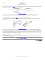
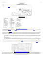
Wednesday, May 24, 2000
Rhodes Service Manual
RHODES Keyboard Instruments U.S.A.
Post Office Box 4137 1300 East Valencia
Fullerton, California 92634
(714) 879-8080
Copyright © 1979 CBS Musical Instruments A Division of CBS Inc.
P/N 34.0119.000 Printed in U.S.A.
Frames (800 X 600) - No Frames (640 x 480)
Rhodes Help Desk
This manual was scanned using OCR and may be subject to typographical errors.
Report any problems or comments to [email protected] .
file:///Macintosh%20HD/Desktop%20Folder/Fender%20Rhodes%20Manual%20%C4/index.html
Page: 1
Wednesday, May 24, 2000
Rhodes Service Manual: Table of Contents
Table of Contents
Section I
Chapter 1
Chapter 2
Chapter 3
Chapter 4
Chapter 5
Latest Design RHODES Piano
The RHODES Tone Source
1-1
The RHODES Modular Action
2-1
Damper Release Bar
2-1
Damper Push Rod Assembly
Damper Module
Action Rail
2-2
2-2
2-3
Harp Supports
Multiple Hammer Flange
2-3
2-4
Instructions For Disassembly
Harp Cover Removal
Nameboard Assembly Removal
3-1
3-1
3-1
Harp Assembly Removal
Damper Release Bar Removal
3-1
3-1
Damper Module Removal
Hammer Removal
Removal of Keyboard Assembly from Cabinet
3-2
3-3
3-3
Stage Piano
Suitcase Piano
3-3
3-4
Action Rail and Harp Removal
Harp Support Removal
Cheekblock Removal
Key Removal
Dimensional Standards and Adjustments
3-4
3-5
3-5
3-5
4-1
Key Dip
Escapement
Damper Clearance
Damper Module Adjustment
Tension
Alignment
4-1
4-1
4-3
4-4
4-4
4-4
Striking Line
Re-Establishing Striking Line
Timbre Adjustment
Volume Adjustment
Tuning The RHODES Piano
4-5
4-6
4-7
4-7
5-1
Electronic Tuning
Stretch Tuning
How to Follow The Chart
5-2
5-3
5-5
Chapter 6
Repair Procedures and Techniques
Tone Generator Assembly Replacement Procedure
Key Pedestal Modification Procedure
Worn Key Bushing Repair Procedure
Key Cap Replacement Procedure
Full-Skirt Type Key Cap
One- And Two-Piece Type Key Cap
Section II Early Design RHODES Piano
Chapter 7
Early Design RHODES Piano - Tone Source (Prior to July 1975)
The Tine
Chapter 8
Early Design RHODES Pianos - Action (Prior to September 1975)
The Action
Chapter 9
Early Design RHODES Pianos - Maintenance and Rejuvenation
Chapter 10 Early Design RHODES Pianos - Dimensional Standards and Adjustments
Key Dip
Damper Control
6-1
6-1
6-4
6-7
6-8
6-9
6-9
Escapement
Signal Strength
Section III Electrical and Electronic Service Aids
Chapter 11 Diagrams, Schematics and Pictorials
10-2
10-4
7-1
7-2
8-1
8-1
9-1
10-1
10-1
10-2
11-1
List of Illustrations
Figure
Number
1-1
1-2
2-1
Title
Tuning Fork Comparison
RHODES Tuning Fork
RHODES Modular Action - Single Key View
Page
Number
1-1
1-1
2-1
file:///Macintosh%20HD/Desktop%20Folder/Fender%20Rhodes%20Manual%20%C4/toc.html
Page: 1
Wednesday, May 24, 2000
2-2
2-3
3-1
3-2
3-3
4-1
4-2
4-3
Rhodes Service Manual: Table of Contents
RHODES Damper Modules - Bass, Mid and Treble Configurations
RHODES Modular Action - Exploded View
2-3
2-4
RHODES Harp/Action Assembly - Exploded View
RHODES Stage Piano - Bottom View
3-2
3-3
RHODES Suitcase Piano Top - Bottom View
RHODES Modular Action - Single Key Depressed
Escapement Distances
3-4
4-1
4-1
Escapement Adjustment Locations
4-2
4-4
Adjustment Location 1
4-3
4-5
RHODES Damper Arm - Tension Adjustment
RHODES Damper Arm - Alignment Adjustment
RHODES Harp/Action Assembly
4-4
4-4
4-6
Timbre Adjustment Diagram
Volume Adjustment Diagram
4-7
4-7
RHODES Tone Bar Assembly
Harp Position for Tuning the RHODES
Typical Dial - Electronic Tuning Device
5-1
5-2
5-4
Stretch Tuning Chart
Tone Generator Assembly Removal/Replacement
5-6
6-2
Tine Cutting Measurement Chart
Felt Strip - Cutting Line Dimension
Key Pedestal - Pencil Line Dimension
6-3
6-5
6-6
Key Pedestal - 5/32" Felt Piece Mounted
Key Pedestal - Felt Modification Complete
Key Bushing Tightener
Key Identification Chart
6-6
6-7
6-8
6-10
RHODES First Stage Tone Bar Assembly
RHODES Second Stage Tone Bar Assembly
RHODES Third Stage Tone Bar Assembly
RHODES Original Tine Design
RHODES Second Stage Tine Design
RHODES Swaged Tine Design
RHODES Original Action Design
RHODES Second Stage Action Design
RHODES Third Stage Action Design
7-1
7-2
7-2
7-2
7-3
7-3
8-1
8-1
8-2
RHODES Fourth Stage Action Design
Tear Drop Hammer Head - Groove Removal
Tear Drop Hammer Head - Reshaping to Striking Line
RHODES Hammer - Shim Placement
Early Design Damper
8-2
9-1
9-1
9-3
9-3
Double-Shoulder Hammer Head
RHODES Early Design Harp/Action Assembly - Cut-Away View
RHODES Early Design Single Key View
9-4
9-5
10-1
RHODES Early Design Harp/Action Assembly - Exploded View
RHODES Original Pickup Coil Series/Parallel Arrangement
RHODES Modified Pickup Coil Series/Parallel Arrangement
RHODES Bus Wire Re-Routing Diagram
Schematic - Preamplifier Assembly - 100 Watt Suitcase and Janus I
Printed Circuit Board - Preamplifier Assembly - 100 Watt Suitcase and Janus I
Schematic - Dual 50 Watt Power Amplifier - 100 Watt Suitcase and Janus I
Schematic - Power Amplifier - Janus I
Printed Circuit Board - +/-15 Volt Regulator - 100 Watt Suitcase and Janus I Power Amplifier
Printed Circuit Board - 50 Watt Power Amplifier - Suitcase Piano
Printed Circuit Board - 50 Watt Power Amplifier - Janus I
Schematic - Preamplifier - 80 Watt Suitcase and Super Satellite
Schematic - Power Module - 80 Watt Suitcase
10-3
10-4
10-4
10-4
11-2
11-3/11-4
11-5
11-6
11-7/11-8
11-9/11-10
11-11/11-12
11-13
11-14
Schematic - Power Supply Regulator Assembly (Peterson Design) -80 Watt Suitcase
Circuit Board Assembly - Power Supply Regulator (Peterson Design) -80 Watt Suitcase
Schematic - Power Amplifier, Master and Slave - Super Satellite
Schematic - Power Control Panel, Master - Super Satellite
Schematic - Power Control Panel, Slave - Super Satellite
Schematic-Converter Kit I
Schematic - Converter Kit II
Schematic - Preamplifier and Power Amplifier (Jordan Design) -Suitcase Piano (Pre 1969)
Connection Diagram - All Printed Circuit Boards - Instructor Console
Schematic - Preamplifier and Power Amplifier - Student Piano (First Version - 1968)
Schematic - Preamplifier and Power Amplifier - Instructor Piano (First Version - 1968)
11-15
11-16
11-17
11-18
11-19
11-20
11-21
11-22
11-23
11-24
11-25
4-6
4-7
4-8
4-9
5-1
5-2
5-3
5-4
6-1
6-2
6-3
6-4
6-5
6-6
6-7
6-8
7-1
7-2
7-3
7-4
7-5
7-6
8-1
8-2
8-3
8-4
9-1
9-2
9-3
9-4
9-5
9-6
10-1
10-2
10-3
10-4
10-5
11-1
11-2
11-3
11-4
11-5
11-6
11-7
11-8
11-9
11-10
11-11
11-12
11-13
11-14
11-15
11-16
11-17
11-18
11-19
11-20
file:///Macintosh%20HD/Desktop%20Folder/Fender%20Rhodes%20Manual%20%C4/toc.html
Page: 2
Wednesday, May 24, 2000
11-21
11-22
11-23
Rhodes Service Manual: Table of Contents
Wiring Diagram - Instructor Console
Schematic - Master Circuit Board - Instructor Console
11-26
11-27
Schematic - Power Supply - Instructor Console
11-28
Page: 3
ACKNOWLEDGEMENT
Appreciation is due to all who have been involved in producing this manual. Specifically, to our Sales Force, the Retail and Service dealers and the artists who offered suggestions. Last, but by
no means least, to our own highly qualified Product Development, Production, Service and Marketing personnel whose many hours of labor and years of expertise have produced what we believe
to be a comprehensive aid to servicing and understanding the RHODES Piano.
RHODES Keyboard Instruments U.S.A.
FOREWORD
Since its inception in 1965, the RHODES Piano has remained relatively constant in terms of design concept. However, there have been changes in the methods of achieving those design concepts.
Those concepts which have remained constant throughout the history of the RHODES are:
1. Method of Tone Production. As will be shown in detail, the Tone is produced by a series of modified tuning forks (one for each note) referred to as "Tone Bar Assemblies." Each such
assembly lies adjacent to an adjustable Pickup. The Pickup Coils are all alike and are adjustable as to gap very much as are the points on the Distributor of an automobile. Because of the
unique construction features, each note can be adjusted for Volume, Timbre and Pitch.
2. The Action. Consisting of only three moving parts, the Action is unique in design. While the structure and materials used have changed, the concept has remained unchanged.
This Manual has a two-fold purpose; one, as a maintenance and repair guide; and two, as a detailed description of the various vintage models together with instructions for upgrading and
modernizing the various models wherever possible.
file:///Macintosh%20HD/Desktop%20Folder/Fender%20Rhodes%20Manual%20%C4/toc.html
Wednesday, May 24, 2000
Chapter One: The Rhodes Tone Source
Page: 1
CHAPTER ONE
THE RHODES TONE SOURCE
The unique tone of your RHODES Piano derives from the principle of the tuning fork. While the common tuning fork has two legs of equal length and mass, the tuning forks in your RHODES
Piano differ from these in one very important way (Figure 1-1). The two prongs of our tuning fork are not of the same mass, shape or size. They are alike only in pitch. The lower, more resilient
leg (Tine) responds visibly to the blow of a Hammer by vibrating in a wide arc at a certain frequency.
Figure 1-1. Tuning Fork Comparison
The upper leg (Tone Bar), while not so visible, does vibrate at the same frequency. The importance of this upper leg can easily be demonstrated by the following simple experiments.
1. Strike any note, preferably in the mid-range of the Piano. With the Sustain Pedal down, squeeze the upper leg with the fingers. The tone will die immediately.
2. Perform the same experiment, but this time touch the upper leg very lightly. The vibration will be distinctly felt under the fingers.
This patented concept of the tuning fork offers many advantages (Figure 1-2). One of these is that the upper leg (Tone Bar) supports some pitch variation in the lower leg (Tine). In other words,
assuming G to be the target pitch, the lower leg could be deliberately tuned to F, F#, G, G# or A without any appreciable loss of support from the upper leg. This opens up a world of
possibilities, as will be shown.
Figure 1-2. RHODES Tuning Fork
You will note a small coil Spring on the lower leg so designed as to be a tight fit. This coil Spring acts as a counter-weight and, therefore, as a pitch control. Moving this Spring will result in a
change of pitch. By this means, then, it is possible to arrive at a fine tuning merely by sliding the Spring to the desired spot on the Tine. See Tuning Your RHODES Piano, Page 5-1.
The Tines in your RHODES Piano, like the strings of a guitar, are subject to breakage under stress. We here at the factory are constantly on the alert for ways to achieve the longest possible life in
these as well as in all other component parts of your Piano. In actual tests, Tines picked at random have withstood in excess of 6,000,000 blows in a test machine. This machine is so constructed
as to simulate actual playing conditions. Despite this, steel wire of even the finest quality, invariably has flaws along its surface. If these microscopically small flaws occur in a node point, they
can become the point of eventual fracture. This is offered to explain the fact that, while one person's Piano may play for many years under constant use with no more than a couple or three broken
Tines, another musician may experience a similar breakage within a shorter period of time.
For reasons just described, the Tines cannot be covered in the general warranty of the Piano.
In anticipation of this, we have devised a simple procedure for replacement - one which the musician can perform in about the time it takes to replace a guitar string. Refer to Tone Generator
Assembly Replacement Procedure, Page 6-1.
TOC - 1 - 2 - 3 - 4 - 5 - 6 - 7 - 8 - 9 - 10 - 11
file:///Macintosh%20HD/Desktop%20Folder/Fender%20Rhodes%20Manual%20%C4/ch1.html
Wednesday, May 24, 2000
Chapter Two: The Rhodes Modular Action
Page: 1
CHAPTER TWO
THE RHODES MODULAR ACTION
DAMPER RELEASE BAR
The Damper Release Bar (Figure 2-1, 22) provides a foot-activated mechanical means of disengaging all Dampers allowing all Tines to vibrate freely.
REFERENCE DESIGNATION
1.
2.
3.
4.
5.
6.
7.
8.
9.
10.
11.
12.
13.
14.
Front Guide Pin Felt
Front Guide Pin
Key Cap
Key
Balance Rail Felt
Harp Support
Tone Bar Assembly
Mounting Spring
Tone Bar Assembly
Mounting Grommet
Tone Bar Assembly
Adjustment Screw
Tone Generator
Mounting Screw
Tone Bar
Tone Generator
Assembly
Tine
Hammer Tip
15.
16.
17.
18.
19.
20.
21.
22.
23.
24.
25.
26.
27.
Hammer
Bridle Strap
Damper Module
Damper Felt
Tuning Spring
Pickup Assembly
Pickup Adjustment
Screw
Damper Release Bar
Damper Release Bar
Pivot Pin
Damper Release Bar
Pivot Pin Locking
Screw
Damper Release Bar
Felt
Multiple Hammer
Flange
Key Pedestal Felt
28. Action Rail Mounting
Screw
29. Action Rail
30. Harp Support-To-Action
Rail Mounting Screw
31. Damper Module
Mounting Screw
32. Push Rod Assembly
Top Felt
33. Push Rod Assembly
34. Push Rod Assembly
Balance Pivot
35. Push Rod Assembly
Bottom Felt
36. Action Rail Mounting
T-Nut
37. Keybed Felt
38. Key Pedestal
Figure 2-1. RHODES Modular Action - Single Key View
The Damper Release Bar is locked in place by two Pivot Pins (Figure 2-1, 23) which slide into two bushed holes provided in the aluminum Harp Supports (Figure 2-1, 6). These pins are held in
place by two locking Screws (Figure 2-1, 24).
DAMPER PUSH ROD ASSEMBLY
The Damper Push Rod Assembly (Figure 2-1, 33) is a short length of wooden dowel capped on each end with felt and held in place by a sleeve built into the back structure of the Piano housing.
Forced upward by the thrust of the Sustain Rod, it, in turn, pushes upward on the back surface of the Damper Release Bar causing its leading edge to bear downward on all of the Dampers thus
disengaging them from the Tines. With the Dampers thus released, all Tines are now free to vibrate sympathetically with the struck tones as is the case with an acoustic piano. The difference
becomes apparent when a comparison is made between the resultant sound of a chord where only those Dampers involved with a particular chord are released and then the sound of the same
chord when all Dampers are released.
1. The Damper Push Rod, in its rest position, should bear solidly against the back surface of the Damper Release Bar. An ideal setting would be that where all play between the Damper
Release Bar and the Damper Arms is removed. This can be accomplished by adding felt either to the top of the Push Rod or to the mating surface of the Damper Release Bar. Extreme care
should be exercised to avoid possible disengagement of the Dampers. Conversely, it can be seen that excessive play or lag in the linkage will result in a loss of touch sensitivity by the
foot.
2. SUITCASE PIANO ONLY:
In its rest position, the bottom surface of the Push Rod should be reasonably flush with the outer surface of the bottom of the Piano. There is a slot on the top surface of the Sustain Rod
providing screwdriver adjustment on the top of the Amplifier Enclosure.
DAMPER MODULE
The Damper Arms are now provided in fixed multiples of twelve known as Damper Modules (Figure 2-1, 17). This change was made to preclude the possibility of side shift in shipping and is the
epitome of simplicity. It consists of tempered aluminum stamped into Modular configurations to accommodate the Damping requirements in Bass, Mid and Treble ranges (Figure 2-2).
Figure 2-2. RHODES Damper Modules - Bass, Mid & Treble Configurations
The Bass Damper Module is shortest with full width Arms to provide the strength and tension needed to properly damp the long Tines in the Bass area. Progressing up the Keyboard to the Treble,
the Tines become shorter and therefore the Damper Modules are designed to provide graduated strength and tension according to the need throughout the range of the Keyboard. In keeping with
the various damping requirements, the Damper Felts as well are designed to accommodate the three areas - the Bass with long, wide Felts; the Middle with Felts of medium length and width; and
the Treble which uses short, narrow Felts.
file:///Macintosh%20HD/Desktop%20Folder/Fender%20Rhodes%20Manual%20%C4/ch2.html
Wednesday, May 24, 2000
Chapter Two: The Rhodes Modular Action
ACTION RAIL
With the Damper Release Bar and the Damper Modules removed, the new Action Rail (Figure 2-1, 29) is revealed to be a sturdy, extremely accurate aluminum extrusion.
HARP SUPPORTS
The new Harp Supports (Figure 2-3, 9) are fabricated from heavy aluminum extrusions sturdy enough to hold the assembly in place undamaged by a direct six-foot drop.
MULTIPLE HAMMER FLANGE
The Hammer Flange (Figure 2-3, 18) is molded in multiples of twelve. This also was redesigned in this manner to preclude the possibility of side shift in shipping.
It should be noted that the Multiple Flanges are molded of a hard A. B. S. material with a 15% teflon content, thus providing lifetime lubrication.
REFERENCE DESIGNATION
1. Keybed
2. Cheekblock
3. Cheekblock Rear
Mounting Screw
4. Harp Support Mounting Screw
5. Keybed Mounting Screw
6. Captive-Washer Mounting Nut
7. Harp Support-to-Action
Rail Mounting Screw
8. Washer
9. Harp Support
10. Nylon Pivot Bushing
11. Damper Release Bar
Pivot
12. Damper Release Bar
13. Pivot Mounting Screw
14. Damper Module
Mounting Screw
15. Damper Module
16. Damper Felt
17. Hammer Flange
Mounting Screw
18. Multiple Hammer
Flange
19. Hammer
20. Hammer Tip
21. Action Rail
22. Key
23. Nameboard Mounting
Screw
24. Nameboard
25. Key Cap
26. Guide Pin
27. Guide Pin Felt
28. Cheekblock Front
Mounting Screw
Figure 2-3. RHODES Modular Action - Exploded View
TOC - 1 - 2 - 3 - 4 - 5 - 6 - 7 - 8 - 9 - 10 - 11
file:///Macintosh%20HD/Desktop%20Folder/Fender%20Rhodes%20Manual%20%C4/ch2.html
Page: 2
Wednesday, May 24, 2000
Chapter Three: Instructions for Disassembly
CHAPTER THREE
INSTRUCTIONS FOR DISASSEMBLY
Access to the specific areas for needed adjustments or repair is easily accomplished by following the procedures outlined here.
1. Harp Cover Removal
The Cover is formed of A. B. S. material and is practically impervious to damage. To remove, lift up on the two back corners of the molded top. With this done, simply pull the front
edge free.
2. Nameboard Assembly Removal
Disconnect Harp Cable from Harp Jack. With a #2 Phillips Screwdriver, loosen and remove the four (4) screws which mount the Nameboard to the Cheekblocks (two (2) of which are
found behind the Nameboard on each end). After removing screws, lift Nameboard Assembly up and away.
3. Harp Assembly Removal
The Harp Assembly (Figure 3-1) consists of three major assemblies. The Harp Frame, the Tone Bar Rail and the Pickup Rail.
The Tone Bar Rail and the Pickup Rail are seated into the Harp Frame and secured by fourteen (14) Mounting Screws. Two metal Harp Brackets are then mounted to join the two.
The Harp Assembly is secured to the two aluminum Harp Supports by four (4) Screws (two (2) on each end) as well as the Harp Pivot Links located on each end. Complete removal of
the Harp, then, is accomplished by removing the four Mounting Screws as well as the two Screws which secure the Harp Pivot Links.
4. Damper Release Bar Removal
The Damper Release Bar (Figure 2-3, 12) is secured to the aluminum Harp Supports by two removable Pivot Pins (Figure 2-3, 11).
a. Loosen one Screw (Figure 2-3, 13) on either end of the Damper Release Bar.
b. With a small flat-blade screwdriver, slide the Pivot Pin out from the Damper Release Bar through the Nylon Bushing (Figure 2-3, 10) in the Harp Support (Figure 2-3, 9).
c. Slide the entire Damper Release Bar loose from the Bushing in the other Harp Support.
Removal of the Damper Release Bar is required in order to reach the Damper Modules for adjustment or removal.
Figure 3-1. RHODES Harp/Action Assembly - Exploded View
5. Damper Module Removal
a. Remove Damper Module Mounting Screws.
b. Carefully push down on each Damper Arm with one hand and gently pull Bridle Strap forward with the other hand so as to slide Bridle Strap away from the formed tongue in the
Damper Arm without causing damage to the tongue.
c. Pull Damper Module out of detent lip in Action Rail.
6. Hammer Removal
It is not necessary to unscrew or displace any of the supporting structures to remove a Hammer. Hold the Hammer Head with the thumb and index finger then rotate either left or right
while at the same time twisting on the vertical axis until the protruding ear (pin) pops out of the Hammer Flange. Then, simply lift out, exercising care to ease the Bridle Strap off the
Damper Arm Tongue.
7. Removal of Keyboard Assembly from Cabinet
CAUTION
This procedure should be accomplished with the Nameboard
Assembly mounted to prevent the Keys from falling out.
file:///Macintosh%20HD/Desktop%20Folder/Fender%20Rhodes%20Manual%20%C4/ch3.html
Page: 1
Wednesday, May 24, 2000
Chapter Three: Instructions for Disassembly
Figure 3-2. RHODES Stage Piano - Bottom View
Stage Piano
a. Position the Piano so that the Keys are pointing up with the bottom surface of the Cabinet facing you (Figure 3-2).
CAUTION
Before proceeding with Step b., support the Keybed with one
hand to prevent the Keybed from falling out when the
Mounting Screws are removed.
b. Using a #2 Phillips Screwdriver, remove the two Screws (Figure 3-2, 1) which secure the Cabinet to the Cheekblock cleat on the Keybed.
c. Remove the two large Screws (Figure 3-2, 2) which mount the Keybed to the Cabinet.
d. Place Piano on its bottom surface and remove Keyboard Assembly by lifting out of Cabinet.
Suitcase Piano
Proceed as with a Stage Piano, again observing the CAUTION on the previous page, following Steps a, b, and c. In addition, since the bottom surface on the Suitcase Piano is of a
thinner plywood than the Stage Piano, the four Glides (Figure 3-3, 1) must be removed as well. Proceed with Step d.
Figure 3-3. RHODES Suitcase Piano Top - Bottom View
8. Action Rail and Harp Support Removal
NOTE
The Action Rail is securely locked to both Harp Supports by
means of the Harp Support-To-Action Rail Mounting Screws.
While these Screws can easily be removed, it is suggested that
the two Harp Supports and the Action Rail be maintained as
a 3-piece Assembly.
a. Place the Keyboard on its bottom surface as in a playing position.
b. Remove the Captive-Washer Nuts that secure the Harp Supports to the Keybed.
c. Exercising care not to lose the T-Nuts from the under side, remove the Action Rail Mounting Screws.
d. Grasp the Action Rail with both hands and lift off the three-piece assembly.
9. Harp Support Removal
a. Disassemble Piano as outlined through 7. b.
b. Remove the Harp Support-To-Action Rail Mounting Screws.
c. Lift Harp Support up and away from Action Rail.
10. Cheekblock Removal
This operation is accomplished by removing both the front and rear Cheekblock Mounting Screws.
11. Key Removal
After removing the Nameboard Assembly, simply lift up on the front of the Key to free it from the front and center Guide Pins, then pull the Key out from under the Hammer.
TOC - 1 - 2 - 3 - 4 - 5 - 6 - 7 - 8 - 9 - 10 - 11
file:///Macintosh%20HD/Desktop%20Folder/Fender%20Rhodes%20Manual%20%C4/ch3.html
Page: 2
Wednesday, May 24, 2000
Chapter Four: Dimensional Standards and Adjustments
Page: 1
CHAPTER FOUR
DIMENSIONAL STANDARDS AND ADJUSTMENTS
This chapter deals with the important dimensional standards for maximum performance of your RHODES Piano and adjustments available to maintain that performance.
1. Key Dip. The distance of downward travel of the Key Front (Figure 4-1, 1) is called "Key Dip." This dimension should be 3/8" ± 1/32", that is, from 11/32" to 13/32" (9.525 ±
0.794mm or 8.731mm to 10.319mm).
Figure 4-1. RHODES Modular Action - Single Key Depressed
CAUTION
When Key Dip is changed, reestablishment of Escapement
and Striking Line is required.
2. Escapement. The gap remaining between the Hammer Tip and the Tine (Figure 4-1, 3) with the Key depressed is called "Escapement". This Dimension varies from the extreme Bass (left)
Tone Bar to the extreme Treble (right) Tone Bar and should be as follows (Figure 4-2).
Figure 4-2. Escapement Distances
The philosophy behind this variation is that while the ideal Escapement for the most responsive touch is 1/32" (0.794mm), the whipping action of the Tine in response to the Hammer blow
increases as it becomes longer toward the Bass end of the Keyboard making this ideal setting impossible.
In order to maintain touch sensitivity through Escapement variation, the Neoprene Hammer Tips are graduated in height as well as hardness from extreme Bass through extreme Treble.
There are presently five gradation of hardness in the Hammer Tips and therefore, corresponding height differences. They are:
Hammer Tip Number
Durometer Reading
(Hardness)
Height
1 through 30
30
1/4" (6.350mm)
31 through 40
50
5/16" (7.938mm)
41 through 50
70
3/8" (9.925mm)
51 through 64
90
7/16" (11.112mm)
65 through 88
Wrapped (extra hard)
7/16" (11.112mm)
As is apparent from the above chart, there is a 1/16" (1.588mm) height increase from one Hammer Tip section to the next, except in the extreme Treble area, or 3/16" (4.762mm) overall Hammer
Tip height increase from Bass to Treble (left to right).
The precise change points of the Hammer Tips are subject to individual taste. While the factory settings are listed above, some musicians prefer to continue the Tips of the 90 durometer clear up to
Hammer Number 67 or beyond. This is done to avoid the sharp change in tone characteristics experienced as a result of the difference in Tip hardness. This provides further opportunity for
customizing in accordance with individual taste.
A quick glance at Figure 4-3 will reveal that there are two ways of achieving a fine, custom adjustment of the Escapement Distances.
file:///Macintosh%20HD/Desktop%20Folder/Fender%20Rhodes%20Manual%20%C4/ch4.html
Wednesday, May 24, 2000
Chapter Four: Dimensional Standards and Adjustments
Page: 2
Figure 4-3. Escapement Adjustment Locations
a. Each of the Tone Bar Assemblies is separated from the Tone Bar Rail by two adjustable coil Springs. By means of these, the height of each Tone Bar Assembly can be raised to
1/2" (12.700mm) or lowered to 3/16" (4.762mm) - factory setting is 3/8" (9.525mm). From Figure 4-4 it can be observed that this adjustment increases or decreases the
Escapement Distance.
Figure 4-4. Adjustment Location 1
NOTE
Any major change of adjustment by this means requires
re-alignment of Timbre, Volume and Damper Settings.
b. Adding or subtracting shims from the Harp Supports (Figure 4-3, 2) should be resorted to ONLY for the purpose of establishing Escapement at the extreme Bass (left) Tone Bar
(1/4" minimum to 3/8" maximum) (6.350mm minimum to 9.525mm maximum) and the extreme Treble (right) Tone Bar (1/32" minimum to 3/32" maximum) (0.794mm
minimum to 2.381mm maximum).
Having been introduced to the adjustments available to you in achieving the best Escapement settings for optimum touch response, you should strive to tailor the Escapement settings in accordance
with the particular style of play employed by the person who plays the Instrument. A sensitive musician will be looking for extremely close settings in the Mid- and Upper-range. A musician who
plays heavy, strong octaves in the Bass area will require even greater Escapement distances in the left hand area. Thus, you now have the tools to customize the action to the individual tastes and
needs of the musician.
3. Damper Clearance. Although the Bridle Strap is part of the Hammer Assembly, it functions as an integral part of the Damper System. It is designed to engage a 'Hook" which is formed
into the arm of the Damper Module at approximately its mid-point. As the Hammer swings upward, the Bridle Strap pulls the Damper Arm downward thus disengaging the Damper Felt
from the Tine. As the Hammer Tip strikes the Tine, the Damper is at the point of maximum Clearance (Figure 4-1, 4) allowing the Tine to vibrate unimpeded. Damper Clearance should be
3/8" to 1/2" (9.525mm to 12.700mm).
4. Damper Module Adjustment. The Damper Module is subject to easy adjustments. With the Hammer in its rest position, the Damper Felt (Figure 2-3, 16) should bear against the Tine
sufficiently firm so that the sound will be damped immediately following the Hammer blow. Conversely, the Damper ideally clears the Tine by at least 3/8" to 1/2" (9.525mm to
12.700mm) when the Key is depressed.
To maintain this relationship, there are two adjustments possible.
a. Tension. Each Damper Arm is actually a Leaf Spring. Tension can be increased or decreased by "ironing" a slight curve in the part with your two fingers. Another way is to pull
upward or downward on the arm at Point "A" (Figure 4-5). Added tension will result in a stiffer Damper response.
Figure 4-5. RHODES Damper Arm Tension Adjustment
b. Alignment. With Tension thus established, proper Damper coordination is achieved by bending the forward portion of the Damper Arm up or down (Figure 4-6).
Figure 4-6. RHODES Damper Arm - Alignment Adjustment
There are four possible conditions which could result in malfunction.
CONDITION
SOLUTION
The Tine is out of adjustment in its vertical aspect (Escapement).
The factory setting places the Tines slightly above dead center of the Pickup. See Timbre
Adjustment, Page 4-7.
The Damper Release Bar is bearing down excessively, thus disengaging or partially
disengaging the Damper from the Tine.
See Damper Push Rod Assembly, Page 2-2.
The Damper Arm has sustained damage sufficient that it no longer bears firmly against
Tine (Tension).
Remove Damper Release Bar and disengage Bridle Strap. With Damper Arm thus free,
note if it assumes a position similar to the neighboring Arms. If so, bend upward slightly
on the surface nearest the point where it is mounted to Action Rail. The aluminum is of an
alloy purposely chosen to invite this type of adjustment. Caution should be exercised to
avoid excessive correction which would result in some loss of touch control due to the
strong resistance thus introduced in opposition to the upward travel of the Hammer.
The leading edge of the Damper has been bent downward. The leading edge referred to is
that portion of the Damper Arm which extends forward from the Bridle Strap tongue and
thus actually provides adjustment possibilities in terms of higher or lower setting of the
Damper Felt (Alignment).
With Bridle Strap in place and having determined that none of the first three conditions
exist, notice whether the particular Damper Felt is in approximate vertical alignment with
the neighboring Felts. If not, with the fingers of two hands, bend this portion of the
Damper Arm upward while exercising care that in doing so, you do not disturb the
configuration of the back portion of the Damper Arm, and thus inadvertantly introduce the
previous condition.
5. Striking Line. "Striking Line" is the term used to describe the best place along the length of each Tine to aim the striking edge of the Hammer. Like the "sweet spot" of a baseball
bat, there is a point of maximum response. This was determined by a painful trial process and resulted in the precise curve given to the Tone Bar Rail.
Proper Striking Line is assured by setting the Harp in such a way as to arrive at an approximate dimension of 2-1/4" (57.150mm) between the leading edge of the Hammer Tip
file:///Macintosh%20HD/Desktop%20Folder/Fender%20Rhodes%20Manual%20%C4/ch4.html
Wednesday, May 24, 2000
Chapter Four: Dimensional Standards and Adjustments
Page: 3
and the leading edge of the Tone Generator (Figure 4-1, 2). This dimension should be taken at the extreme Bass (left) Tone Bar. At the extreme Treble (right) Tone Bar, this
dimension is approximately 1/8" (3.175mm).
RE-ESTABLISHING STRIKING LINE
1. Remove the Harp/Keybed Assembly from the Cabinet following procedures outlined in Chapter Three.
2. To re-establish proper Striking Line, remove two (2) Harp Mounting Screws (Figure 4-7) on the Bass (left) side of the Harp and one (1) Harp Mounting Screw on the Treble
(right) side of the Harp located closest to the Keys. Loosen but do not remove the remaining Screw. In addition, remove one (1) Harp Pivot Link Mounting Screw on the Bass
(left) side of the Harp which attaches the Harp Pivot Link to the thread-grooved slot formed in the side of the Harp Support.
Figure 4-7. RHODES Harp/Action Assembly
3. While striking Middle C, slide the Bass (left) side of the Harp forward and back until ultimate tone clarity and volume response is achieved. Move on to F below Middle C then to
C below Middle C following the same procedure. Because of the precise curve of the Harp, when these three notes satkfy your ear, all others will be within tolerable limits.
4. When the new Harp location has been established, use extra holes provided or sink new holes through the steel Harp Frame and through the top surface of the aluminum Harp
Supports using a #7 drill. Secure the Harp by re-installing the Harp Mounting Screws.
5. Attach the Harp Pivot Link by re-installing the Harp Pivot Link Mounting Screw along the thread-grooved slot on the side of the Harp Support.
6. Mount the Harp/Keybed Assembly in the Cabinet by reversing the disassembly procedure outlined in Chapter Three.
TIMBRE ADJUSTMENT
Timbre Adjustment is accomplished by manipulating the Timbre Adjustment Screw (Figure 2-1, 9) until the end of the Tine rests on a plane slightly above dead center of the Pickup
(Figure 4-8). Let your ear guide you in this procedure.
Figure 4-8. Timbre Adjustment Diagram
VOLUME ADJUSTMENT
Slide Pickup Arms in or out to establish a gap between Pickup and Tine of between 1 16" (1.588mm) and 1/8" (3.l75mm) as shown in Figure 4-9.
Figure 4-9. Volume Adjustment Diagram
It should be noted that the smaller the gap between Tine and Pickup, the greater the volume of sound. More important -- the more pronounced the DYNAMIC RESPONSE.
By Dynamic Response is meant "percentage of volume increase in response to increased weight of touch." In Pianos built since March 1972, a gap of 0.020" (0.5080mm) can be
accommodated in the middle and upper ranges.
NOTE
When Timbre and Volume Adjustments are made,
Pitch should be re-established. See TUNING THE
RHODES PIANO, Page 5-1.
TOC - 1 - 2 - 3 - 4 - 5 - 6 - 7 - 8 - 9 - 10 - 11
file:///Macintosh%20HD/Desktop%20Folder/Fender%20Rhodes%20Manual%20%C4/ch4.html
Wednesday, May 24, 2000
Chapter Five: Tuning the Rhodes Piano
Page: 1
CHAPTER FIVE
TUNING THE RHODES PIANO
Generally speaking it can be said that the Piano will not "go out of tune". Certainly it does not go generally out of tune over the entire Keyboard as does the traditional string piano.
What may happen is that one or more notes may go out of tune because of a loose Tuning Spring or as a result of Tine fatigue under the stress of constant heavy blows. Under these conditions
tuning simply requires pitch comparison with the tone an octave below and shifting of the Tuning Spring until pitch alignment is achieved. In the case of extreme Tine fatigue, the Tine should be
replaced.
An extremely helpful feature is the easy removal of the Tone Generator Assembly (Tine portion) from the Tone Bar by unscrewing the Tone Generator Mounting Screw; thus, should a Tine
become damaged for any reason, replacement will be easy and inexpensive. Replacement Tone Generator Assemblies are available in Kit form, with the Tine 4-3/8 inches (111.125 mm) in length.
This length Tine will accommodate the "Heavy Traffic" area where the highest incidence of fatigue and breakage is likely to occur. These can be cut to desired length with a pair of side-cutters.
For detailed removal and replacement procedures, refer to Chapter 6, Page 6-1.
On each Tine there is a crimped coil Spring so fitted that it can be moved by hand with some effort (Figure 5-1). By design it fits tightly enough to resist normal stresses. Ideally, it remains fixed
firmly in place unless deliberately moved.
Figure 5-1. RHODES Tone Bar Assembly
This Spring acts as a counter-weight and thus provides a vernier control of pitch. Moving it outward, away from the fixed end of the Tine, will cause a drop in pitch. Conversely, moving it
inward, toward the fixed end of the Tine, will cause a rise in pitch. The total range thus achieved could be as much as 1-1/2 steps above or below optimum.
Theoretically and ideally, once set, the pitch remains unchanged until deliberately altered by purposed relocation of the Tuning Spring (counter-weight). Pitch control by this means is not as
difficult a task as with a standard piano. The novice is invited to test his skill by taking the following steps.
1. Remove the Harp Mounting Screws and rotate the Harp to a vertical position (Figure 5-2).
Figure 5-2. Harp Position For Tuning The RHODES
2. Mark the letter names of the Tone Bars on the Tone Bar Rail.
3. With the amplifer and speaker on and volume up, pluck the Tine at Middle C with the finger of the right hand. At the same time, pluck C an octave below Middle C with the left hand.
4. Move the Tuning Spring at Middle C slightly upward so as to cause a slight rise in pitch.
5. As you continue to pluck both Middle C and C an octave below, slowly slide the Spring back.
6. As you do this, you will observe the following phenomenon. As the upper C approaches synchronization with the low C you will notice a beat. As the middle C approaches maximum
synchronization the speed of the beat will reduce.
7. Continue this process until there is no longer a discernable beat. Repeat this entire procedure several times until you become familiar with the technique. With some practice you should be
able to restore pitch synchronization within five seconds.
8. Proceed up and down the Keyboard precisely as you would with a string piano. The job will be much easier in this case since there will be no need to tune unisons.
ELECTRONIC TUNING
There are several brands of electronic tuning devices on the market. Most of these operate roughly on the principle of the strobe light. There is a spinning disk, the speed of which is accurately
calibrated. A control knob allows for scale tone changes. Assuming you set the control dial at C, there is a microphone which "hears" the pitch of the Bar you are tuning. Its vibrations are
interpreted as flashes of light. These in turn are superimposed on the spinning disk. If the two are in synchronization, the wheel will appear to be stopped. If the Tone Bar is high in pitch, the
wheel will appear to rotate clockwise, etc. Moving the Tuning Spring downward will slow the speed of the Tine. This will cause the strobe wheel to slow its movement until finally, when your
adjustment is correct, the wheel will stop, indicating that the Bar is "in tune".
The various electronic devices have another feature - some are more sophisticated than others. It is a deliberate and controllable means of calibrating the entire mechanism with reference to the 60
cycle signal coming from the electrical outlet. With calibration thus achieved and with the control dial set at Zero, the machine supposedly is now set at A440. This is a standard arbitrarily
determined as an international standard and means merely that A above Middle C will vibrate at precisely 440 vibrations per second. Because of such a standard, it is possible to tune an instrument
in California with reasonable assurance that it will be "in tune" with a piano in New York. Or, that 24 pianos delivered to a school as a "lab" will all arrive tuned alike.
Certain musicians will demand a more sensitive tuning than what would be the result if the tuning machine were set at A440 for the duration of the entire tuning procedure. This brings up a term
known as "Stretch Tuning".
STRETCH TUNING
Stretch tuning is a procedure widely followed by the piano tuning profession. It recognizes a phenomenon of the human ear whereby tones in the upper range of a keyboard will sound "flat" even
though they are calibrated with extreme precision. Fortunately for all, a consensus has long since been agreed upon as to the exact amount of stretching. A piano so tuned creates the impression of
great tonal brilliance. Preliminary to a description of stretch tuning, a bit more basic information is in order.
For the purpose of standardization, the word "semitone" is used to describe the difference in pitch between any tone and the tone 1/2 step above. One one-hundredth part of a semitone is called a
"cent". Thus, to raise a certain tone "one cent" is to raise it from its original A440 setting by one one-hundredth of a semitone.
All electronic tuning devices make use of this standard and have a dial by which the technician can deliberately change the basic setting of a given tone by as many 'cents" above or below a given
optimum as he chooses, merely by altering the setting on the dial of his tuning device (Figure 5-3).
file:///Macintosh%20HD/Desktop%20Folder/Fender%20Rhodes%20Manual%20%C4/ch5.html
Wednesday, May 24, 2000
Chapter Five: Tuning the Rhodes Piano
Page: 2
Figure 5-3. Typical Dial - Electronic Tuning Device
Armed with this standard, it now becomes possible for the technician to plot with precision the exact degree of stretch and to achieve exact synchronization of tuning between two instruments even
though one may be tuned in New York and the other in California.
"Stretch Tuning", as described here, means the deliberate and precise raising or lowering in pitch of a given range of tones along the scale by one or more "cents" according to a predetermined
standard.
NOTE
RHODES Pianos are not stretch tuned at the factory.
Instead, they are tuned to equal temperament.
The schedule offered here is a carefully determined approximation. This schedule is the result of the collective tuning experience of a great number of qualified concert tuners.
Since this is an approximation, deviation from this in qualified hands is certainly allowable. However, with the tools just described, it is also possible to plot with equal precision the exact degree
of deviation decided upon. The end result then, will be that two pianos so tuned will synchronize with such precision as to play together as one.
To ease your work in following this schedule, it is suggested that you mark with a pencil on the Tone Bar Rail the exact place where the basic setting changes and the number of "cents" change
dictated by the chart (Figure 5-4, Page 5-6).
How to Follow the Chart
Typical procedure might be as follows:
First, calibrate your tuning machine in accordance with Manufacturer's instructions, making sure that the arrow is set on Zero. Next, tune A above Middle C. Follow with A#, B, C, C# and D.
Observing your Chart, you will notice that the next tone, D#, is supposed to be tuned 1 Cent sharp. So, turn the dial on the tuning machine one one-hundredth of a Semitone (1 Cent) sharp. Now
continue tuning D#, E, F, F#, and G. Again, observing your Chart, notice that the next tone, G#, is supposed to be tuned 2 Cents sharp. So, again, re-set the dial on your tuning device. This
time set the dial two Cents sharp. Continue this procedure until you reach the highest note on the Piano.
Now, go back to your starting point at A above Middle C. Move the dial back again to Zero. Observe G# to the left of A. The Chart shows this to be 1 Cent flat. Therefore, following the
procedure, which by now is familiar to you, turn the dial to the left of Zero a distance of 1 Cent and tune G#. Continue downward, tuning G, F#, F and E.
The next note, D#, is one and one-half Cents flat. D, C4, C, B, A and G# are all two Cents flat, etc. Continue observing the schedule shown on the Chart until you reach the lowest note on the
Piano.
Upon completion of this, you will have Stretch Tuned the Piano in accordance with the best tuning tradition. Now, treat yourself to a performance and enjoy the rare brilliance that only Stretch
Tuning can achieve.
Should you ever wish to revert to standard, equal temperament tuning, simply set your dial to Zero and leave it there as you proceed throughout the entire Keyboard. This may be necessary where
you feel the need to synchronize with an organ, for instance, where it is impossible to Stretch Tune.
It should be noted also that with all instruments where any option can be realized, the musician will automatically follow the concept of Stretch Tuning. This may explain why an instrument tuned
to equal temperament may sound dull and flat.
Figure 5-4. Stretch Tuning Chart
file:///Macintosh%20HD/Desktop%20Folder/Fender%20Rhodes%20Manual%20%C4/ch5.html
Wednesday, May 24, 2000
Chapter Six: Repair Procedures and Techniques
Page: 1
CHAPTER SIX
REPAIR PROCEDURES AND TECHNIQUES
TONE GENERATOR ASSEMBLY REPLACEMENT PROCEDURE
Since all Tines throughout the pitch range are of the same configuration and vary only in length, and since the Tines can easily be cut to size by means of a pair of side cutter pliers, it follows that
all the musician needs is a set of replacement Tines.
To aid the musician, replacement Tines are packaged in Kits of six. In each Kit is an assortment of Tuning Springs and a complete cutting chart.
Each of the six Tines comes already pressed into the little cross-piece called the Tone Generator. Thus, the two parts when joined together become the "Tone Generator Assembly." The Kit then is
known as the Tone Generator Assembly Replacement Kit.
NOTE
Originally, RHODES manufactured only a Seventy-three Key
Model Piano and Tone Generator Assemblies were identified
on the Tone Bar as Number 1 through 73. In actuality, our
Seventy-three Keys are E8 through E80 as compared to an
Eighty-eight Key Piano whose keys are identified Al through
C88.
When manufacture of our Eighty-eight Key Pianos was begun,
our problem of identifying the seven notes preceding our
Number 1 (E8) was solved by designating all seven as Number 0 since the Tone Bars were identical.
Since, we have determined that conformity to the industry
standard would be less confusing. Therefore, Tone Bar
Assemblies (which include Tone Generator Assemblies) will
be identified on our Eighty-eight Key Pianos as 1 through 88,
and on our Seventy-three Key Pianos as 8 through 80.
To perform the replacement procedure, you will need the following tools:
1. A Phillips Screw Driver (No.2)
2. A pair of Side Cutters
3. A 1/4" (6.350mm) and a 5/16" (7.938mm) Wrench
Complete replacement requires only the following simple steps.
1. Remove the Harp Cover.
2. Remove the Tone Generator Mounting Screw (Figure 6-1) using the 5/16" (7.938mm) wrench.
Figure 6-1. Tone Generator Removal/Replacement
3. Remove the four Screws which secure the Piano Harp Frame to The Harp Supports (Figure 4-7) and stand the Harp vertically on its edge.
4. Consult the cutting chart (Figure 6-2) in the Tone Generator Assembly Replacement Kit and cut the Tine to length with a pair of sharp side cutters.
5. Mount the Tuning Spring.
6. Secure the new replacement by installing and tightening the Tone Generator Mounting Screw.
7. Turn on the Amp with the Volume at maximum setting.
8. Re-set Volume by loosening the Volume Adjustment Screw with 1/4" (6.350mm) wrench and sliding the Pickup Arm in or out as you play.
9. Re-set Timber (tone color) by rotating the Timbre Adjustment Screw with #2 Phillips screwdriver, as you play.
10. With your left hand, pluck the Tine an octave below the Replacement Assembly. With your right hand, pluck the Replacement Tine and slide the Tuning Spring until pitch alignment is
accomplished.
file:///Macintosh%20HD/Desktop%20Folder/Fender%20Rhodes%20Manual%20%C4/ch6.html
Wednesday, May 24, 2000
Chapter Six: Repair Procedures and Techniques
Figure 6-2. Tine Cutting Measurement Chart
11. Check for pitch once more.
12. Secure Harp and replace Harp Cover.
Since absolute contact between the Tone Generator and the Tone Bar is necessary, the Tone Generator Assembly Mounting Screw is installed at the factory with power equipment. In some cases,
removal of this screw will seem almost impossible; however, it can be accomplished in the following manner:
1. Remove both Screws mounting the complete Tone Bar Assembly to the Tone Bar Rail.
2. Place Screws, Grommets, Washers, and Mounting Springs in a safe place to avoid loss.
3. Set Tone generator between jaws of a bench vise and tighten jaws securely.
4. With a 5/16" (7.938mm) ratchet wrench, loosen and remove Tone Generator Mounting Screw.
In the event that a bench vise and a 5/16" (7.938mm) ratchet wrench are not available, the Tone Bar may be held in one hand while loosening and removing the Tone Generator Mounting Screw
with the other using a 5/16" (7.938mm) box-end wrench.
Tone Generator Assembly Replacement requires only the reversal of the preceeding procedure.
KEY PEDESTAL MODIFICATION PROCEDURE
In June 1978, the present Key Pedestal configuration (Figure 2-1, 38) was incorporated into the Piano. This development provides smoother, faster action or feel. Pianos built prior to that time
may be modified by carefully pursuing the following procedure.
1. Remove Action Rail by following procedures outlined on Page 3-4. Maintain Hammer Assemblies in their mounted position.
2. Locate Action Rail on bench well away from other parts of the Piano and other equipment that may be harmed by the chemicals to be used.
Materials required for this procedure are:
Silicon Spray
Naphtha Based Solvent/Solution (i.e., Lighter Fluid)
Clean, Absorbent Cloth
WARNING
Prior to using the Silicon Spray and Naphtha Based Solvent,
place a drop of each on the side of a Hammer to determine
that no adverse effect will result from the chemical reaction
with the plastic.
file:///Macintosh%20HD/Desktop%20Folder/Fender%20Rhodes%20Manual%20%C4/ch6.html
Page: 2
Wednesday, May 24, 2000
Chapter Six: Repair Procedures and Techniques
Page: 3
3. Place the Action Rail with Hammers and Dampers intact up-side-down to allow for easy access to the Felt on the Hammer Butt.
4. Saturate each Felt with Silicon Spray two or three times allowing 10 minutes soaking interval between each saturation application.
5. When the Felt's adhesive has been sufficiently reduced, slide each piece off from the Hammer Butt.
6. Thoroughly clean each Hammer Butt with a clean cloth soaked in the Naphtha Based Solvent, making sure that all trace of the adhesive is removed.
7. Using a clean cloth soaked in the Naphtha Based Solvent, thoroughly wipe each Key Pedestal relieving them of any trace of dust and/or lubrication that may have previously been applied.
8. Remove the Replacement Felts from the package and arrange in a straight line on a flat surface.
9. Measure 5/32" (3.969mm) in from one edge of the Felt Strip (Figure 6-3) and slice along the strip of Felts with a sharp knife ensuring that both pieces retain the protective paper backing.
Lay aside the 1-13/32" (35.719mm) Felt Strips.
Figure 6-3. Felt Strip - Cutting Line Dimension
10. Scribe a pencil line along the top of each Key Pedestal 1-1/16" (26.988mm) from the rear surface farthest from the Key Cap (Figure 6-4).
Figure 6-4. Key Pedestal - Pencil Line Dimension
11. One by one, remove 5/32" (3.969mm) felt pieces from the paper backing and place them on the Key Pedestal in front of (closest to the Key Cap) the scribed pencil line so that the pencil
line is visible after the 5/32" (3.969mm) Felt Piece is securely mounted (Figure 6-5).
Figure 6-5. Key Pedestal - 5/32" Felt Piece Mounted
12. Remove the 1-13/32" (35.719mm) Felt Strips from the paper backing one at a time and place them on the top surface of the Key Pedestal with the 5/32" (3.969mm) Felt Piece mounted.
Be particularly careful to ensure that the 1-13/32" (35.719mm) Felt Strip is flush with the front (closest to the Key Cap) surface of the Key Pedestal (Figure 6-6).
Figure 6-6. Key Pedestal - Felt Modification Complete
file:///Macintosh%20HD/Desktop%20Folder/Fender%20Rhodes%20Manual%20%C4/ch6.html
Wednesday, May 24, 2000
Chapter Six: Repair Procedures and Techniques
Page: 4
13. Any excess of the 1-13/32" (35.719mm) Felt Strip protruding in the rear may be trimmed off, however, function will not be impaired if it is left untrimmed.
14. Lightly spray the Felt Strip with Silicon Spray. An excess of the Silicon may reduce the Felt's adhesive and cause the Felt to fall off.
15. Replace the Action Rail by reversing Action Rail Removal procedure outlined on Page 3-4.
After the Piano has been completely reassembled, check for Escapement (Page 4-1) and determine that a "Double-Stroking" condition does not exist.
WORN KEY BUSHING REPAIR PROCEDURE
After years of normal use, the Balance Rail Key Button and Front Pin bushings will show wear, causing the Keys to move sideways creating the sensation of a "sloppy action".
By the use of the proper tools and techniques, this can be easily cured, giving the piano a tight, "like new" feeling.
The easiest method is achieved by the use of a piano technician's tool, called a Key Bushing Tightener (Figure 6-7).
Figure 6-7. Key Bushing Tightener
To use this tool, all that is necessary is to remove the Keys and place them on a flat surface. Then insert the tool into each affected slot, and gently tap the top of the tool with a hammer. This will
cause the Key wood to be squeezed toward the center, making the gap for the guide pin smaller. Replace the Keys in the Piano.
If a Bushing Tightener is not available, approximately the same effect can be accomplished with a pair of strong needle-nose pliers.
With the pliers, carefully squeeze the wood together at each bushing slot (too much force can break the wood) causing the bushings to be squeezed inward.
The third technique is to replace the bushings.
With a sharp knife, carefully trim away the worn bushings. Then apply a white glue to each side of the bushing slot. Install new felt (obtainable from any piano supply house) and clamp the felt in
place with a key bushing wedge, or clamp. (The Bushing Tightener can be used for this purpose also.) After the glue has dried, trim away the excess felt and replace the Keys in the Piano.
An alternative to the felt bushing is plastic bushing inserts. Instead of installing felt after the glue is applied, press in the plastic inserts. After the glue dries, replace Keys in Piano.
After any bushing tightening or replacement, always make sure the bushings are not too tight, and that the Keys do not stick.
KEY CAP REPLACEMENT PROCEDURE
Periodically a customer will request a new Key because some blow has caused a fracture, or a cigarette burned one or more of the Key Caps.
Instead of replacing a Key, it is a standard practice of piano technicians to resurface, or recap the Key.
To resurface a Key, it is first necessary to identify the Key and its Cap style. Refer to Key Identification Chart (Figure 6-8), Page 6-10.
Once the Key Name, manufacturing type (Cap thickness), and Cap style have been determined, you can then proceed with removing the damaged Cap.
The same type of white key cement can be used for the One-piece, Two-piece or Full-skirt style Cap. Because the surface of the Key where the Cap adheres to the wood is visible, a glue that dries
white is preferred for the One- and Two-piece style cap.
Piano key cement is available at piano parts and supply companies. If piano key cement is not readily available, Duco cement will work acceptably.
If white piano key cement is not available, you can make a glue that dries white by mixing Duco cement with 30% acetone and adding small Key Cap chips and shavings from the broken Key
Caps. Place the Duco in a sealable container. Add enough acetone to increase the total volume 25% to 30%. Add in the broken chips and stir. As the chemical dissolves the plastic, continue to add
more chips and allow them to dissolve. Continue stirring and adding chips until you are satisfied with the color of the glue. Before using the glue, make sure all plastic chips are dissolved. The
texture should be thick and smooth, about the consistency of syrup.
FULL-SKIRT TYPE KEY CAP
To replace the Full-skirt type Cap (Figure 6-8, B.), it is first necessary to remove the old Cap. Since the Cap is damaged, it is of no consequence if you break the Cap further when you remove it.
Using pliers and a sharp knife, break the Cap off, piece by piece, all the white being careful not to chip or otherwise damage the Key itself.
After the old Cap is removed, sparingly apply piano key cement to the appropriate part of the Key.
After the glue has been applied, slide the Cap on to the Key, making sure that it is pushed in place so that the end of the Key is against the inside front of the Cap. Put rubber bands around the
Key to hold the Cap firmly in place until the glue dries.
ONE- AND TWO-PIECE TYPE KEY CAP
Basically, replacing the One-piece (Figure 6-8, A) and the Two-piece (Figure 6-8, B) type Key Caps is the same as replacing the Full-skirt type Cap. However, the technique does vary slightly in
the removal and clamping processes since the One- and Two-piece Caps cover only the top and front of the Key.
file:///Macintosh%20HD/Desktop%20Folder/Fender%20Rhodes%20Manual%20%C4/ch6.html
Wednesday, May 24, 2000
Chapter Six: Repair Procedures and Techniques
Figure 6-8. Key Identification Chart
To remove the Cap, a sharp X-acto type knife is used to cut between the Cap and the wood of the Key. Always slice with the grain of the wood so as to minimize cutting the wood.1 Carefully
slide the knife between the Cap and the Key. Moving slowly with light pressure, slide the knife under the Cap from one end of the Key to the other, causing the Cap to come loose from the Key
but not peeling or cutting any wood from the Key itself.
For the One-piece type Cap (and the front of the Two-piece type if removal is necessary) also slide the knife between the front of the Key and the Cap, carefully removing the front of the Cap
without damaging the Key.
After the Cap has been removed, scrape or sand the glue and Cap residue from the Key. Also make sure any damage to the Key is repaired (add wood putty to any gouges, etc.). Make sure the
Key surface is as smooth and level as possible.
Apply the glue liberally to the surface that is being capped. Spread the glue so that there are no air gaps.
Carefully place the new Cap on the Key. Slide the Cap across the Key slightly to help spread the glue. Align the new Cap on the Key so that there is equal overhang on both sides of the Key and
that the relief area of the head of the Cap is flush with the relief area of the head of the Key. The head of the Cap at the front should then overhang the front piece (on a Two-piece Cap) by
approximately 1/16" (1.588mm). On the One-piece Cap, the front should be firm against the front of the Key and the Cap should be centered so that there is equal overhang on both sides of the
Key. After the Cap is properly aligned, clamp the Cap in place with spring clamps and a block or plate2 to keep the clamps from scratching the plastic Cap. After the clamps and blocks are in
place, make sure the Caps are still properly aligned and realign if necessary. Set the Key aside and allow appropriate time to dry, which will depend on the glue used.
After the glue has dried, remove the clamps and blocks and trim down the excess overhang on the sides of the Key with a flat file (a Vixen-type file does a very quick and neat job). File away the
excess plastic until the Cap is flush with the sides of the Key. For a nice smooth appearance, scrape (with an X-acto type knife) or sand away file marks in the plastic and round off the front
corners of the head of the Cap.
The Key is now ready to be replaced in the Piano.
1. Heating the plastic Cap with a heat gun will soften the plastic to allow easier removal.
2. Spring clamps and plates for the tops and fronts are available from piano supply companies.
TOC - 1 - 2 - 3 - 4 - 5 - 6 - 7 - 8 - 9 - 10 - 11
file:///Macintosh%20HD/Desktop%20Folder/Fender%20Rhodes%20Manual%20%C4/ch6.html
Page: 5
Wednesday, May 24, 2000
Chapter Seven: Early Design Rhodes Pianos - Tone Source
Page: 1
CHAPTER SEVEN
EARLY DESIGN RHODES PIANOS - TONE SOURCE (Prior to July 1975)
In the broad claim of our original patent, No.2,972,922, the Tone Source is described as a "tuning fork of unequal legs". In other words, we deviate from the traditional concept of a tuning fork
in that, while both legs of the fork vibrate at the same frequency, the lower leg is more resilient and, as a consequence, responds more positively to the blow of a Hammer. It is to our advantage to
construct this lower leg in such a way as to render it as resistant to wear and fatigue as possible. In pursuit of this, the Tone Bar Assembly has gone through three major changes through the
years.
1. In the original Piano, the Tone Bar Assembly (tuning fork) was a single piece of cast iron which was suspended in a metal channel. The bottom leg was a length of piano wire of a
diameter of .075" (1.905mm) (Figure 7-1).
Figure 7-1. RHODES First Stage Tone Bar Assembly
2. In the next stage the Assembly was constructed as shown in Figure 7-2. Several improvements were accomplished by this change.
a. The Tone Generator Assembly (Figure 7-2) was now removeable for easy replacement.
b. Timbre adjustment was more easily accomplished.
c. Escapement distance was more easily adjusted.
3. In an attempt to further improve the tone quality and at the same time to reduce weight, we came up with the current Tone Bar design, which we call the "twisted steel bar" (patent No.
3,644,656) (Figure 7-3).
Figure 7-2. RHODES Second Stage Tone Bar Assembly
Figure 7-3. RHODES Third Stage Tone Bar Assembly
THE TINE
In our original design, the "Tine" (bottom leg of tbe tuning fork) consisted of a length of piano wire .075 (1.905mm) in diameter (Figure 7-4). Fine tuning was accomplished by means of a
slideable length of coil Spring which was crimped to produce a friction fit.
Figure 7-4. RHODES Original Tine Design
Later, in an attempt to distribute the vibrational shock created by a heavy Hammer blow, the wire was tapered (Figure 7-5).
file:///Macintosh%20HD/Desktop%20Folder/Fender%20Rhodes%20Manual%20%C4/ch7.html
Wednesday, May 24, 2000
Chapter Seven: Early Design Rhodes Pianos - Tone Source
Figure 7-5. RHODES Second Stage Tine Design
This taper was accomplished by the "centerless grinding process". This new configuration added considerable life expectancy to the Tine.
As a result of some six years of developmental procedure, a major breakthrough was accomplished in the processing of these new tapered Tines. Instead of the centerless grinding process, we
introduced the current Tine (Figure 7-6). In this new innovation the Tine is formed by the swaging process, a process which by its very nature adds strength to the part by compacting the outer
surface (skin) of the Tine.
Figure 7-6. RHODES Swaged Tine Design
In a comparative shock test, our first Tine withstood 40,000 heavy Hammer blows; the second Tine withstood 1,500,000 blows, and the swaged Tine was still going after 6,000,000 blows.
While it is the nature of even the finest steel to deteriorate when shocked by stresses beyond its elastic limit and thus finally to crystalize and break, we feel that in this new process we now have
reached the ultimate in providing a part capable of withstanding indefinitely all but the most withering treatment.
TOC - 1 - 2 - 3 - 4 - 5 - 6 - 7 - 8 - 9 - 10 - 11
file:///Macintosh%20HD/Desktop%20Folder/Fender%20Rhodes%20Manual%20%C4/ch7.html
Page: 2
Wednesday, May 24, 2000
Chapter Eight: Early Design Rhodes Pianos - Action
CHAPTER EIGHT
EARLY DESIGN RHODES PIANOS - ACTION (Prior to September 1975)
Fundamentally, there has been no deviation from the original design principle, though the actual configuration of the parts has changed.
THE ACTION
The original Hammer Assembly appeared as shown in Figure 8-1.
Figure 8-1. RHODES Original Action Design
The Hammer Head was of the conventional "tear drop" design. The Hammer Shank and Hammer Butt were formed from wood and therefore tended to suffer the weaknesses of wooden parts,
such as off-center holes, drifting holes, warping, etc.
An interim change involved the insertion of an aluminum clip (Figure 8-2, A) on top of the Key Pedestal. This was done to increase the acceleration of the old Hammer design.
Figure 8-2. RHODES Second Stage Action Design
The next generation of Hammers featured a molded Shank and a molded Flange (Figure 8-3). These parts were made of CYCOLAC, a material which has withstood the test of time and has
proven to be dimensionally far superior to its predecessor, besides being practically impervious to variations in temperature and weather. At this same time the Felt Strip originally attached to the
cam curve of the Hammer was instead placed on the newly designed Pedestal surface of the Key.
Figure 8-3. RHODES Third Stage Action Design
The "tear drop" Hammer Head was excellent for standard pianos, however, it tended to wear a groove, and as the groove deepened, the quality of sound deteriorated. Replacement was
cumbersome and costly.
While this type of Head was retained for awhile, another innovation followed soon (Figure 8-4). It consisted of a wooden Head with a Felt Tip, which was easily removed for replacement. This
was a major step forward in that replacement could be done inexpensively by the musician.
Figure 8-4. RHODES Fourth Stage Action Design
At the same time, research was going on with a type of Neoprene which would be a useable substitute for the felt Tips. Felt - being what it is - was still subject to grooving. The formation of a
groove is costly in tone production, since the walls of the groove act as dampers. It was hoped that a material could be found which would end the problem of grooving. The Neoprene Tips
proved superior in every way and were introduced into the line early in 1971, following extensive testing.
file:///Macintosh%20HD/Desktop%20Folder/Fender%20Rhodes%20Manual%20%C4/ch8.html
Page: 1
Wednesday, May 24, 2000
Chapter Nine: Early Design Rhodes Pianos - Maintenance
Page: 1
CHAPTER NINE
EARLY DESIGN RHODES PIANOS - MAINTENANCE AND REJUVENATION
This Chapter of the manual will be devoted to maintenance procedure and to description of the ways in which the various vintage models can be adapted to newer standards.
1. Suppose you have a Piano of the vintage depicted in Figure 8-1 and wish to bring it up to current sound standards. Proceed as follows:
a. Examine the condition of the Hammer Heads. If the grooves are not more than 3/16" (4.762mm) deep, they can be reshaped by sanding off the outer surface. To accomplish this,
construct a shaping tool from a 6" (152.4mm) length of wood to which has been cemented a piece of very rough sand paper. Beginning at Points A and Al work upward toward
the crown - taking off enough of the outer layer of felt to remove all trace of the groove (Figure 9-1).
Figure 9-1. Tear Drop Hammer Head - Groove Removal
It should be noted that by the method chosen in this shaping process, you have a measure of control over the "striking line" (the point of Hammer contact along the length of the Tine).
Suppose Point A (Figure 9-2) is the optimum point for best tone and volume response. You can shape the Hammer so that the peak of the felt is left or right of center in order to accommodate to
Point A.
You can determine the exact location of Point A by removing all the Mounting Screws from the Harp so that it can be slid back or forward on the Support Blocks. With the Harp free to move,
slide it back or forward as you strike the Key until you locate the point of maximum power response. Next, mark this point on the Tine with a felt pen, slide the Harp to original position, with
Hammer raised, mark a spot on the Hammer Tip where the Felt Tip should be shaped. This procedure should be repeated about every 6th Hammer throughout the scale. The intervening Hammers
can be shaped to the "curve" thus developed.
Figure 9-2. Tear-Drop Hammer Head - Reshaping to Striking Line
b. Next, test Felt hardness by playing the Piano through the mid-range. If the tone quality is harsh, indicating excessive hardness of Hammers, the Felts can be softened by the
"Voicing" process. This is accomplished through the use of a Voicing tool, available in any piano supply house. Failing this, embed a common sewing needle in a hand drill, then
"drill" the needle directly into the Felt at several points in the striking area.
c. If the Hammer Heads are too badly worn for salvage, remove all Hammer Assemblies and install Replacement Hammer Assemblies. The Hammer Assembly will come complete
with Flange and Bridle Strap mounted. It will appear as shown in Figure 8-4A, without Tip.
Proceed as follows:
1. Remove all Damper Shoes by sliding forward (Figure 7-1).
2. Unscrew Flange Screw and remove Hammer by sliding Bridle Strap out over Damper Arm.
3. Mount the new Hammer Assembly by sliding the new Bridle Strap over the Damper Arm then by securing the Assembly with the Flange Screw.
4. Slide all Damper Shoes back into place.
5. Create a 1/8" x 3/8" x 3/8" (3.175mm x 9.525mm x 9.525mm) shim and glue into place on the Hammer Head as shown in Figure 9-3. This is necessary in order to bring
the Hammer Tip up to the full height of the one replaced.
file:///Macintosh%20HD/Desktop%20Folder/Fender%20Rhodes%20Manual%20%C4/ch9.html
Wednesday, May 24, 2000
Chapter Nine: Early Design Rhodes Pianos - Maintenance
Page: 2
Figure 9-3. RHODES Hammer - Shim Placement
6. Secure all Neoprene Tips following the instructions given in the Kit.
7. The new Bridle Straps are slightly shorter than the old, resulting in a lower rest position of the Damper Felts. Adjust these upward to suit by bending the Malleable Wire
Damper Arm (Figure 9-4).
Figure 9-4. Early Design Damper
8. Carefully peel off the red woven Felt from the cam curve of the old Hammers, exercising care to leave a smooth, clean surface, and cement to the top of the Key Pedestal.
This applies whether the Key is as shown in Figure 8-1 or Figure 8-2.
2. Suppose you have a Piano of the vintage depicted in Figure 8-4 but with the type Tone Bars as shown in Figure 7-2, and you wish to restore it. Proceed as follows:
a. Remove all Felt Hammer Tips with a jack knife. Make certain that the maple Hammer Head surface is clean of all Felt and old glue. If the Hammer Head is of the variety shown in
inset Figure 8-4B, remove the back shoulder with a pair of end cutters in order to provide ample surface for the Replacement Neoprene Tips (Figure 9-5).
Figure 9-5. Double-Shoulder Hammer Head
b. Using 3M Super Weatherstrip Adhesive No.8001 available at auto supply stores, or a similar bonding agent, cement the Neoprene Tips following instructions given in the
Hammer Tip Replacement Kit.
1. Remove all Tone Generator Assemblies by removing all Tone Generator Mounting Screws (Figure 8-1).
2. Mount all new Tone Generator Assemblies following instructions given in the Tone Generator Assembly Replacement Kit.
3. Adjust Timbre. See Timbre Adjustment, Page 4-6.
4. Adjust Volume. See Volume Adjustment, Page 4-6.
5. The Felt Tips are slightly taller than the Neoprene Tips, so escapement must be re-established. See Page 4-1.
6. Remove the Harp Mounting Screws (including the Hinge Screw) on the left (Bass) side of the Harp (Figure 9-6, 9).
7. Refer to Step 3., Page 4-6.
8. When you have located this new Harp position to your satisfaction, sink two new holes in the maple Side Support Blocks (use a No.10 drill), then secure the Harp by
remounting the Screws. Next, remount the Hinge by drilling a new hole (No.10) in the side of the Harp Frame. Exercise extreme care in guiding your drill through the
steel so as to avoid plunging the drill into the Pickup. If the Harp/Action Assembly is out of the Cabinet, a new hole can be drilled in the side of the Harp Support Block
to relocate the Hinge, thus avoiding the possibility of damaging the Pickup.
file:///Macintosh%20HD/Desktop%20Folder/Fender%20Rhodes%20Manual%20%C4/ch9.html
Wednesday, May 24, 2000
Chapter Nine: Early Design Rhodes Pianos - Maintenance
1. Tines
2. Dampers
3. Harp Hinge
4. Pickups
5. Preamp Jack
6. Pickup Arms
7. Pickup Mounting Screws
8. Damper Release Bar
9. Harp Mounting Screws
10. Typical Tone Bar
11 & 12. Tone Bar Adjustment Screws
13. Balance Rail Guide Pins
14. Front Rail Guide Pins
15. Nameboard Mounting Screws
Figure 9-6. RHODES Early Design Harp/Acfion Assembly - Cut-Away View
TOC - 1 - 2 - 3 - 4 - 5 - 6 - 7 - 8 - 9 - 10 - 11
file:///Macintosh%20HD/Desktop%20Folder/Fender%20Rhodes%20Manual%20%C4/ch9.html
Page: 3
Wednesday, May 24, 2000
Chapter Ten: Early Design - Standards & Adjustments
Page: 1
CHAPTER TEN
EARLY DESIGN RHODES PIANOS - DIMENSIONAL STANDARDS AND ADJUSTMENTS
1. Key Dip. Key Dip and Hammer travel are controlled by the height of the Action Rail. Key Dip is the term used to describe the downward limit of travel of the Key when depressed. 3/8"
(9.525mm) is ideal. This is controlled by means of shims (Figure 10-1) placed between the Action Rail and the Key Frame. To adjust, remove the entire Action from the box. Along the
back of the Key Frame under the Action Rail will be five wood screws. Remove these, then either remove shims or add shims depending upon whether you wish to reduce or increase the
Key Dip.
Figure 10-1. RHODES Early Design Single Key Views
2. Damper Control. The Damper ideally clears the Tine by at least 3/8" to 1/2" (9.525mm to 12.7OOmm) when the Key is depressed. Conversely, when the Key is at rest, the Damper
should bear firmly on the Tine in order to effectively damp the sound.
To maintain this relationship, there are two adjustments possible.
a. Tension. Refer to Page 4-4.
b. Alignment. Refer to Page 4-4.
3. Escapement. Escapement is the word used to describe the distance between the striking edge of the Hammer Tip and the Tine when the Key is fully depressed. This distance varies from
between 3/16" (4.762mm) and 3/8" (9.525mm) in the Bass section to between 1/16" (1.588mm) and 1/8" (3.175mm) in the Mid section and between 1/32" (0.794mm) and 3/32"
(2.381mm) in the Treble section. The shorter the Escapement distance, the more sensitive the touch.
The Escapement distance could be called the "free throw" area. In other words this is the area of Hammer travel after the energy imparted by the touch is no longer effective. In order to
understand the philosophy, suppose the Escapement distance were 1/2" (12.7OOmm). Under this condition, it would require an extremely sharp blow to impart enough acceleration to the
Hammer to enable it to reach the Tines. Now reverse the situation, suppose that we reduce the Escapement to zero. The lightest feather touch will produce a sound. However, sustained
finger pressure on the Key will cause the Hammer to smother the sound. Now back off a bit. Raise the Escapement to the point where the Hammer can no longer smother the sound. This
becomes the ideal setting.
To achieve the ideal Escapement setting, there are several adjustments possible depending upon the vintage Piano involved.
a. To decrease the Escapement distance, compress both Escapement Adjusting Springs (Figure 4-4). This will lower the entire Tone Bar Assembly thus reducing the gap. Once this
is accomplished re-establishment of Timbre and Volume setting is done in the usual way.
b. If the Escapement is excessive throughout the entire Piano, proceed as follows:
1. Remove the two Side Support Blocks (Figure 10-2).
file:///Macintosh%20HD/Desktop%20Folder/Fender%20Rhodes%20Manual%20%C4/ch10.html
Wednesday, May 24, 2000
Chapter Ten: Early Design - Standards & Adjustments
Figure 10-2. RHODES Early Design Harp/Action Assembly - Exploded View
2. Using a table saw, shave off the desired amount from the top surface of each Block, approximately 1/16" (11.588mm) to 1/8" (3.175mm).
3. Replace the Assembly, then reset the Dampers for maximum performance.
c. An alternate method of accomplishing the same thing is to remove all Hammer Tips, add a Shim, then replace the Tips, as outlined on Pages 9-2 and 9-3. This procedure, while
perhaps a bit more tedious, requires no equipment nor re-adjustment of Dampers.
As also is the case in string pianos, the Escapement distance in the Bass section should be greater than in the middle and upper sections. This requirement is even more
pronounced in our Instrument due to the wide arc of Tine movement encountered. Escapement distance on Tone Bar 1 could be 3/8" (9.525mm). Insufficient Escapement in this
area invites "double stroking" with an accompanying disturbing sound.
Signal Strength:
Originally the 73 Pickup Coils were joined in a series/parallel arrangement as shown in Figure 10-3.
Figure 10-3. RHODES Original Pickup Coil Series/Parallel Arrangement
Later, basic voltage output was quadrupled by changing the series/parallel arrangement as shown in Figure 10-4.
Figure 10-4. RHODES Modified Pickup Coil Series/Parallel Arrangement
This change can be made on any of the older Pianos simply by re-routing the bus wires as shown in Figure 10-5. The output impedance then becomes approximately 2500 ohms.
Figure 10-5. RHODES Bus Wire Re-Routing Diagram
TOC - 1 - 2 - 3 - 4 - 5 - 6 - 7 - 8 - 9 - 10 - 11
file:///Macintosh%20HD/Desktop%20Folder/Fender%20Rhodes%20Manual%20%C4/ch10.html
Page: 2
Wednesday, May 24, 2000
Chapter 11: Diagrams, Schematics and Pictorials
CHAPTER ELEVEN
DIAGRAMS, SCHEMATICS AND PICTORIALS
Due to the specialized nature of Electric and/or Electronic repairs, RHODES limits this Chapter to Circuit Board Pictorials, Wiring Diagrams, and Schematics with the intention of aiding the
qualified technician.
CAUTION
To avoid possible personal injury or damage to the unit, all electronic repair and adjustment should be accomplished by a qualified technician.
11-1: Schematic - Preamplifier Assembly - 100 Watt Suitcase and Janus I
11-2: Printed Circuit Board - Preamplifier Assembly - 100 Watt Suitcase and Janus I
JPEG Image
Parts List
11-3: Schematic - Dual 50 Watt Power Amplifier - 100 Watt Suitcase and Janus I
11-4: Schematic - Power Amplifier - Janus I
11-5: Printed Circuit Board - +/-15 Volt Regulator - 100 Watt Suitcase and Janus I Power Amplifier
JPEG Image
Parts List
11-6: Printed Circuit Board - 50 Watt Power Amplifier - Suitcase Piano
JPEG Image
Parts List
11-7: Printed Circuit Board - 50 Watt Power Amplifier - Janus I
JPEG Image
Parts List
11-8: Schematic - Preamplifier - 80 Watt Suitcase and Super Satellite
11-9: Schematic - Power Module - 80 Watt Suitcase
11-10: Schematic - Power Supply Regulator Assembly (Peterson Design) -80 Watt Suitcase
11-11: Circuit Board Assembly - Power Supply Regulator (Peterson Design) -80 Watt Suitcase
11-12: Schematic - Power Amplifier, Master and Slave - Super Satellite
11-13: Schematic - Power Control Panel, Master - Super Satellite
11-14: Schematic - Power Control Panel, Slave - Super Satellite
11-15: Schematic-Converter Kit I
11-16: Schematic - Converter Kit II
11-17: Schematic - Preamplifier and Power Amplifier (Jordan Design) -Suitcase Piano (Pre 1969)
11-18: Connection Diagram - All Printed Circuit Boards - Instructor Console
11-19: Schematic - Preamplifier and Power Amplifier - Student Piano (First Version - 1968)
11-20: Schematic - Preamplifier and Power Amplifier - Instructor Piano (First Version - 1968)
11-21: Wiring Diagram - Instructor Console
11-22: Schematic - Master Circuit Board - Instructor Console
11-23: Schematic - Power Supply - Instructor Console
TOC - 1 - 2 - 3 - 4 - 5 - 6 - 7 - 8 - 9 - 10 - 11
file:///Macintosh%20HD/Desktop%20Folder/Fender%20Rhodes%20Manual%20%C4/ch11.html
Page: 1