1
Inc.
Web: http: // www. pearl - hifi . com
E-mail: custserv @ pearl - hifi . com
❦
Perkins Electro-Acoustic Research Lab, Inc.
86008, 2106 33 Ave. SW, Calgary, AB; CAN T2T 1Z6
Ph: + .1.403.244.4434 Fx: + .1.403.245.4456
Engineering and Intuition Serving the Soul of Music
Please note that the links in the PEARL logotype above are “live”
and can be used to direct your web browser to our site or to
open an e-mail message window addressed to ourselves.
To view our item listings on eBay, click here.
To see the feedback we have left for our customers, click here.
This document has been prepared as a public service . Any and all trademarks
and logotypes used herein are the property of their owners.
It is our intent to provide this document in accordance with the stipulations with
respect to “fair use” as delineated in Copyrights - Chapter 1: Subject Matter and
Scope of Copyright; Sec. 107. Limitations on exclusive rights: Fair Use.
Public access to copy of this document is provided on the website of Cornell Law School
at http://www4.law.cornell.edu/uscode/17/107.html and is here reproduced below:
Sec. 107. - Limitations on exclusive rights: Fair Use
Notwithstanding the provisions of sections 106 and 106A, the fair use of a copyrighted work, including such use by reproduction in copies or phono records or by any other means specified by that section,
for purposes such as criticism, comment, news reporting, teaching (including multiple copies for classroom use), scholarship, or research, is not an infringement of copyright. In determining whether the use
made of a work in any particular case is a fair use the factors to be considered shall include:
1 - the purpose and character of the use, including whether such use is of a
commercial nature or is for nonprofit educational purposes;
2 - the nature of the copyrighted work;
3 - the amount and substantiality of the portion used in relation to the copyrighted work as a whole; and
4 - the effect of the use upon the potential market for or value of the copyrighted work.
The fact that a work is unpublished shall not itself bar a finding of fair use if such finding is made
upon consideration of all the above factors
♦
PDF Cover Page
♦
♦
Verso Filler Page
♦
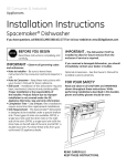
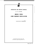
400F/FL
AC VOLTMETER
OPERATING
AND
SERVICE
MANUAL
�
HEWLETT
PACKARD
�---
HEWLETT
CE RTI FI CATION
The Hewlett-Packard Company certifies that this instrument was
thoroughly tested and inspected and found to meet its published
specifications when it was shipped from the factory. The Hewlett
Packard Company further certifies that its calibration measure
ments are traceable to the U.S. National Bureau of Standards to
the extent allowed by the Bureau's calibration facility.
WARRANTY AND ASSISTANCE
All Hewlett-Packard products are warranted against defects in
materials and workmanship. This warranty applies for one year
from the date of delivery, or, in the case of certain major compo
nents listed in the operating manual, for the specified period. We
will repair or replace products which prove to be defective during
the warranty period provided they are returned to Hewlett
Packard. No other warranty is expressed or implied. We are not
liable for consequential damages.
Service contracts or customer assistance agreements are available
for Hewlett-Packard products that require maintenance and re
pair on-site.
For any assistance, contact your nearest Hewlett-Packard Sales and
Service Office. Addresses are provided at the back of this manual.
OPERATING
AND
(HP PART
MANUAL
NO. 00400-90005)
MODEL
AC
SERVICE
400F/FL
VOLTMETER
SERIALS
PRE FIXED:
734-
Appendix C. Manual Backdating Changes.
adapts this manual to serials prefixed 617-.
Copyright
P. O.
01795·2
Hewlett-Packard Company 1966
Box 301. Loveland,
Colorado, 80537 U. S. A.
Printed:
JAN 1968
♦
Verso Filler Page
♦
Model 400F/FL
T .... LE OF CONTENTS
Section
Page
I
GENERAL INFORMATION . . .... .. 1-1
.. .... .. 1-1
1-1. Description
1-4. Option (400F only) .......... 1-1
1-6. Instrument and Manual Identification . 1-1
Section
INSTALLATION
2-1. Introduction
2-3. Initial Inspection
2-5. Power Requirements
2-7. Grounding Requirements
2-10.Installation ..... ..
2-12.
Bench Mounting . ..
2-14. Rack Mounting
2-16.
Combination Mounting
2-18.Repackaging for Shipment
Page
2-1
2-1
2-1
2-1
2-1
2-1
2-1
2-1
2-1
2-1
SectiOn
OPERATING INSTRUCTIONS
3-1. Introduction . . . ...
3-3. Controls. Indicators and Connectors
3-5. Meter Mechanical Zero Adjustment
(400F Only) ... ....
3-7. Turn-On Procedures
3-8. AC Voltage Measurements
3-g. DC Measurements .. .
3-10. Wide Band AC Amplifier
3-11. 400F with Option 01
Page
3-1
3-1
3-1
Section
IV
THEORY OF OPERATION
4-1. General ......
4-3. Block Diagram Description
4-5. Schematic Theory
4-7.
Input Attenuator
4-9.
Preamplifier .
4-13. Post Attenuator
4-15. 100 KHz Low Pass Filter
4-17.
Meter Amplifier
4-22.
Meter Bridge
4-27.
Power Supply ..... .
Page
'-1
'-1
'-1
'-1
'-1
'-1
'-1
'-1
'-2
'-2
.-3
D
m
3-1
3-1
3-1
3-2
3-2
3-2
Table of Contents
List of Tables
List of Illustrations
Page
Section
5-1
V MAINTENANCE . .... ...
5-1
5-1. Introduction ... . ...
5-1
5-3. Test Equipment Required
5-1
5-5. Performance Checks
5-1
5-10. Top Cover Removal
5-12.
Accuracy and Frequency Response
.... ... . . .. .. 5-1
Checks
5-14.
Range Tracking Check .. .. . . 5-2
Input Impedance Check . .. ... 5-3
5-16.
5-19.Alignment and Calibration Procedures 5-3
Cover Removal and Replacement . 5-4
5-21.
5-26. Meter Mechanical ZeroAdiustment 5-4
5-4
5-28.
Meter Calibration
5-5
5-32. Attenuator Alignment . .
5- 5
5-34.
A2Ql Bias Adjustment .
5-5
5-36. Replacement of A2C37*
5- 5
5-39.Troubleshooting Procedure
5-6
5-44.
Power Supply . .. .. .
5-6
5-46.
AmplUiers . ......
5-6
5-48. Meter Bridge .. ... .
5-6
5-50.Etched Circuit Board Repair
Section
VI SCHEMA TIC
6-1. Introduction
Section
REPLACEABLE PARTS
7-1. Introduction
7-4. Ordering Information
7-6. Non-Listed Parts
vn
Page
6-1
. 6-1
Page
7-1
7-1
7-1
7-1
Appendix
A
CODE LIST OF MANUFACTURERS
Appendix
B SALES AND SERVICE OFFICES
LIST Of TA_US
Page
1-0
Number
1-1. Specifications
3-1. EHect of Distortion on Average Responding Meter ....... .
3-2. AC Amplifier Gain Factors
3-1
3-2
5-1. Test Equipment ..... .
5-0
5-2. Full Scale Calibration Tolerances (400F). 5-2
Number
Page
5-3. Full Scale Calibration Tolerances (400FL) . 5-2
5-6
5-4. Troubleshooting Guide ..
5-5. Power Supply Voltages ..
5-6
5-6. Preamplifier Voltages ..
5-6
5-6
5-7. Meter Amplifier Voltages
5-6
5-8. Meter Bridge Voltages
7-2
7-1. Replaceable Parts
LIST OF ILLUSTR"'TlONS
Number
page
1-0
1-1. Model 400F/FL AC Voltmeter
3-0
3-1. Location of Controls and Indicators
3-1
3-2. External Battery Connection ...
3-3
3-3. Impedance Correction Graph ....
4-1. Functional Circuit Diagram
4-0
4-2. Filter Attenuation Characteristics .
4-1
4-2
4-3. Simplified Diagram of Metering Circuit
5-1. Accuracy and Frequency Response Check
.. 5-0
Setup .. ..... ... ....
,
01795-1
.
Number
Page
5-2. Alternate Accuracy and Frequency Response Check Setup . . . .. . . ..
5-3
5-4
5-3. Input Impedance Check Setup . . . ..
5-4. Location 01 Internal Adjustments
5-4
6-1. Model 400F/FL Range Switch and plo
Internal Wiring Data . .......
6-2
6-2. Model 400F/FL Component Location .6-3/6-4
6-3. Model 400F/FL Schematic Diagram . 6-3/6-4
7-1. Location of Important Mechanical Parts . 7-0
ill
♦
Verso Filler Page
♦
Section I
Model 400F / FL
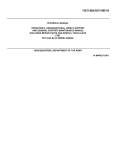
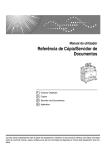
Figure 1-1.
ModeI400F/FL AC Voltmeter
Table 1-1.
Specifications
-hp- Model 400F/FL
-hp- Model 400F/FL
Voltage Range: lOO Jl V to 300 V full scale. 14
ranges in 1, 3, 10 sequence.
Frequency Range: 20 Hz to 4 MHz.
Calibration: Responds to absolute average value
of applied signal, calibrated in rms volts.
Noise Referred to Input: ( 1000 ohm termination)
RANGE
Filter In
Filter Out
300 Jl V to 300 V
100 Jl V
Input Impedance: 10 megohms shunted by 25 pF
on the 100 Il V - 300 mV ranges and 10 meg
ohms shunted by 10 pF on the 1 V - 300 V
ranges.
Amplifier AC Output: 1 V rms open circuit
for full scale meter indication; output imped
ance 600 oluns, 20 Hz to 4 MHz.
Meter Response: < O. 7 seconds after application
of signal.
1-0
Recovery From Overload:
overload.
<
2 seconds for 80 dB
AC Power: 115 or 230 volts ± 10%. 50 to 1000
Hz, 5 watts.
External Battery Operation: Terminals are pro
vided on rear panelj positive and negative
voltages between 35 V and 55 V are required.
Current drain from each voltage is approxi
mately 45 mA.
Temperature Range: 0 to +550c.
Weight:
Net: 6 Ibs. (2. 7 kg).
Shipping: 91bB.
(4 kg).
Dimensions: 6-1/2" high, 5-l/8"wide, 11" deep
(165. 1 x 130. 2 x279. 4 mm).
01795-3
Model 400F/FL
Section
I
SECTION
GENERAL
INFORMATION
to +2 instead of from -12 to +2. The dB scale is
placed at the top of the meter face for better
resolution.
1-1. DESCRIPTION.
The �hp- Models 400F and 400FL are versatile
Both models can be
used as wideband amplifiers.
The Model 400F is
primarily intended for voltage measu rements, where
How
as the Model 400FL is primarily a dB meter.
ever. both meters indicate both volts and dB. The
40DF has a linear ac scale with a logarithmic dB
scale underneath. and the 400FL has a linear dB
scale with a logarithmic ac scale underneath. Since
the difference in scales is the only difference between
the two instruments. this manual will use the term
400F/FL in reference to both instruments.
1-2.
ac voltmeters and dB meters.
1-6. INSTRUMENT AND MANUAL
IDEN TIFATION.
1-7. Hewlett-Packard instruments are identified by
a two-section, eight-digit serial number (000-00000).
If the first three digits of the serial number on your
instrument do not agree with those on the title page
of this manual, change sheets supplied with the man
ual will define differences between your instrument
and the Model 400F /FL described in this manual.
1-8. If a letter prefixes the serial number, the
instrument was manufactured outside the United States.
1-3. Figure 1-1 shows both the Model 400F and the
Mode1400FL. Table 1-1 is a list of specifications.
1-9. BACKDATIN G IN FORMATION.
1-4. OPTION (400F ONLY).
1-10. Appendix C contains backdating information
that adapts this manual to instruments with serials
prefixed 617.
1-5. Option 01 is a standard -hp_ Model 400F AC
Voltmeter which has a dB scale that reads from -15
Table 1-1.
Specifications (Cont'd)
MODEL 400F
± (% Full Scale +
Accuracy:
% Reading)
300 �V TO 300 V RANGES
Frequency
40 Hz
20 Hz
r
±
(2
+
2)
I
1 MHz
100 Hz
±(1 + 1 )
I
±(1/2 + 1/2)
I
2 MHz
±Cl
+ 1)
I
4 MRz
± (2
+
2)
I
100 �V RANGE
Frequency
60 Hz
30 Hz
±
(2
+
2)
100 kHz
±(1
+
1)
500 kHz
±1
+0
-7
MODEL 400FL
Accuracy: ± % Reading
300 �V TO 300 V RANGES
Frequency
40 Hz
20 Hz
±4
1 MRz
100 Hz
±2
2 MHz
±2
±1
4 MHz
±4
100 IJ,V RANGE
Frequency
60 Hz
30 Hz
±4
01795-2
100 kHz
±2
500 kHz
+1 -8
1-1
Mot.!cI4IXJ1·/I· L
Sectioll l
M,u.lln'Jm O�fllrJ.ad AC ,�n"WolH' lOUoI!jt" mpt.lt tu
thl'
, mV ttm)IJ'1Ih 300 m" 'oI'l\ln mu\I not
Ol:tttJ th. �.aI\J" ,huwn
,
�OO
...
0
•
Q.
I
r--
300
11)
�
-'
0
>
200
U
�
�
100
c
20
lit
-22
10K
401(
201(
_00' .... "
FREOUENCY (Ht)
AC
Inp... 1 to It•• 1 V II'I,o�h 300 V "flgU
na'" 500 V .m,
"._np,
mu,t nul
TI'I, limit 0' 1000 V de
m ... l' not
be ncud", on
.nv
,,�,
Table 1·2. Performance Characteristics.
1·2
v
♦
Verso Filler Page
♦
Section
ModeI400F/FL
SECTION
IT
11
IN STALLATION
2-1. INTRODUCTION.
2-2. This section contains information and instructions
necessary for the i.nstallation and shipping of the
Model 400F and 400FL voltmeters. Included are
initial inspection procedures. power and grounding
requirements. installation information. and instructions
for repackagtng for shipment.
2-3. INITIAL INSPECTION.
2-4. This instrument was carefully inspected both
mechanically and electrically before shipment. It
should be physically free of mars or scratches and
in perfect electrical order upon receipt. To confirm
thiS. the instrument should be inspected for physical
damage in transit. Also cheekior supplied accessories,
and test the electrical performance of the instrument
using the procedure outlined in Paragraph 5-5. If
there is damage or deficiency. see the warranty on
the inside front cover of this manual.
2-5. POWER REQUIREMENTS.
using an adapter frame (-hp- Part No. 5060-0797).
The adapter frame is a rack frame that accepts any
combination of submodular units. It can be rack
mounted only. For additional information. address
Inquires to your -hp- Sales and Service Office. (See
Appendix B for office locations.)
2-16.
2-17. The Model 400F/FL may be mounted in
combination with other submodular units by using a
Combining Case (-hp- Model 105lA or 1052A). The
Combining Case is a full-module unit which accepts
various combinations of submodular units. Being a
full-module unit. it can be bench or rack mounted
and is analogous to any full-module instrument.
2-18. REPACKAGING FOR SHIPMENT.
2-19. The following paragraphs contain a general
guide for repackaging of the instrument for shipment.
Refer to Paragraph 2-20 if the original container is to
be used; 2-21 if it is not. If you have any questions.
contact your local -hp- Sales and Service Office. (See
AppendLx B for office locations.)
2-6. The Model 400F/FL can � operated from any
source of 115 or 230 volts at 50 to 1000 cycles or
from two 35 to 55 volt batteries connected to the rear
panel BATTERY terminals. The 115/230 V slide
switch on the rear panel selects the desired line
voltage. Power dissipation is 5 watts maximum.
-------
2-9. To preserve the protection feature when
operating the instrument from a two-contact outlet.
use a three-prong to two-prong adapter and connect
the green pigtail on the adapter to ground.
2 - 10. INSTALLATION.
2.. 11. The Model 400F/FL is fully transistorized;
therefore. no special cooling is required. However.
the instrument should not be operated 1Shere the
ambient temperature exceeds 550C (131 F) or the
relative humidity exceeds 95%.
2-12. BENCH MOUNTING.
2-13. The Model 400F/FL ls shipped with plastic
feet and tilt stand in place. ready for use as a bench
instrument.
2-14. RACK MOUNTING.
2-15. The Model 400F/FL may be rack mounted by
01795-2
NffiE
-------
If the instrument is to be shipped
to Hewlett-Packard for service
or repair. attach a tag to the in
strument identifying the owner
and indicating the service or re
pair to be accomplished; include
the model number and full serial
number of the instrument.In any
correspondence, identify the in
strument by model number. serial
number. and serial number pre
fix.
2-7. GROUNDING REQUIREMENTS.
2-8. To protect operating personnel. the National
Electrical Manufacturers' Association (NEMA) recom
mends that the instrument panel and cabinet be
grounded. All Hewlett-Packard instruments are
equipped with a three-conductor power cable which.
when plugged into an appropriate receptacle. grounds
the instrument. The offset pin on the power cable
three-prong connector is the ground wire.
COMBINATION MOUNTING.
2-20. If original container is to be used. proceed as
follows:
a. Place instrument in original container if
available. If original container is not available,
one can be purchased from your nearest -hp
Sales and Service Office.
b.
Ensure that container is well sealed with
strong tape or metal bands.
2-21. If original container is not to be used. proceed
as follows:
a. Wrap instrument in heavy paper or plastic
before placing in an lnner container.
b. Place packing material aro1.:.nd all sides of
instrument and protect panel face with card
ooard strips.
c. Place instrument and inner container in a
heavy carton or wooden box and seal with
strong tape or metal bands.
d. Mark shipping container with "DELICATE
INSTRUMENT", "FRAGILE" etc.
2-1
♦
Verso Filler Page
♦
Section ill
ModeI400F/FL
r1=====;�12
IojQ()EL 400F" f'ROI(f PANEL
,
MOO£L 400F REAI't P.II NEL
I . U . "'"
.
11
�
.
I
�
.
:.: I I
"' , ....... , ••�". r"""
.. ..,
".U
...." ..
._
�
'"
I �
3
_¥ '
....... .
_-
I
-.
:' -
_."
::
_ ..
_. .
..
.. .//
�)
,
•
-0
,
I
...
I
.
..
"0
... ...
........
.
...·..
0-
-, ""'- ��
.
.
.
.....
,
..
·...'..
r"'"
©� �::jE�'� �
""'-
.
"."
*
@.� :�� ::®
1
6
h
Ll.J
4
('
5
MOOtL 400F"L REAR PANEL
MODEL 400f"L FRONT PANEL
14
.
@', :::�:'�
* ...
"''''
.
.
.....
,
.-
.
.....,.....
, ... .... �� •..,.. r""
..
..'.......
6
::®
@: :�}:
-:..J � : ::
�: :
.
400'/fl-B-Q839A
CD 400F Scale: [ndicates magnitude of applied sig
nal in volts and dBm.
CD Mechanical Zero Adjust: Provides a mechanical
meter zero adjustment.
([) INPUT Terminals: Connects signal to be mea
sured to 400F/FL.
RANGE Selector (St): Selects full scale reading
of meter. DBm reading on scale adds algebrai
cally to dB setting of RANGE selector .
100 KHz LP FILTER Switch (S2): Switches 100
CD KHz
filter either in or out o f circuit.
Line ON Toggle Switch (S3): Applies primary
CD power.
Indicator Lamp: Indicates application
0) ofLINE
primary IXlwer.
Volt Slide Switch (S4): Selects 115 or
CD 115/230
230 volts ac for line operation.
Figure 3- 1.
3-0
o Primary Power Connector:· Line voltage is ap�
plied through this connector.
®
FUSE: Protects instrument against current
overload.
® AC OUTPUT:
Ac amplifier output.
pedance is 6 0 0 n.
Output im
@
BATTERY VOLTAGE Terminals: 400F/FL may
be powered by connecting two 35 to 55 volt bat
teries to these terminals.
®
@
400 F Scale. Option Ol: The dBm scale is placed
uppermost for greater resolution.
400FL Scale: Indicates magnitude of applied sig
nal in volts and dBm. DBm scale is linear, and
voltage scales are logarithmic. This arrange
ment allows better resolution for dB reading.
o dBm= 1mW in 600 n.
Location of Controls and Indicators
01795- 2
Section ID
Model 400F/FL
SECTION
OPERATIN G
III
INSTRUCTION S
3-1. INTRODUCTION.
BATTERY VOLTAGE
3-2. This section contains instructions and information
..1
35-55
necessary for the operation of the 400F/FL AC Volt
meters. Included is identification of controls� indi
35-55
+
cators and connectors. turn on proceduresiand oper
ating instructions.
3-3. CONTROLS, INDICATORS AND
CONNECTORS.
3-4. Each control� indicator, and connector on the
400F/FL is identified and described in Figure 3-1.
t-- jSI
___
3-5. METER MECHANICAL ZERO ADJUSTMENT
-11
(400F ONLY).
3-6. The mechanical zero adjustment i s located in
the center of the instrument front panel. If the meter
pointer does not indicate zero after the instrument has
been off at least one minute. mechanically zero the
meter. following the steps outlined below.
a. Turn instrument power off. and allow at least
one minute for meter pointer to stabilize.
b.
Figure 3-2.
Since the
until
less.
the errors caused by distortions.
Table 3-1.
Effect of Distortion on Average Respond
ing Meter
%
HARMONIC
% DISTORTION
ERROR
(' Fundamental)
MAlL
Any even
a. If line voltage is used, ensure that the 115-230
vac switch (located on the rear panel) is in the
correct position. Turn the line ON toggle
switch to the ON position. The LINE lamp
b.
400F/FL is average re
P OSITIVE
3-7. TURN ON PROCEDURES.
will glow,
applied.
NOTE --------
sponding and rms calibrated, any
distortion will affect the accuracy of
the measurement. Table 3-1 shows
pointer is at zero. Stop when pointer is exactly
on zero. Iipointer overshoots, repeat step b.
pointer moves to the left. repeat whole pro
cedure, but make counterclockwise rotation
+
91
(35-55V)
External Battery Connection
-------
pointer is left of zero and moving upscale.
d. When pointer is exactly over zero, rotate
adjustment screw slightly counterclockwise to
relieve tension on pointer suspension. If
_11
3-8. AC VOLTAGE MEASUREMENTS.
Rotate zero adjustment screw clockwise until
c. Continue rotating screw clockwise
+
92
(35-55V)
indicating
that
line
power
Third
is
If batteries are used, connect two 35 to 55
volt batteries as shown in Figure 3-2. The
Fifth
0.1
0.000
0.5
0.001
1.0
2.0
0.005
0.020
0.1
0.033
0.5
0.168
0.167
1.0
0.338
0.328
2.0
0.687
0.667
0.1
0.5
O.
0.020
101
0.020
0.099
0.205
0.195
line ON switch is not in the circuit when bat
1.0
teries are used, therefore an external DPST
2.0
switch should b e used to provide a means for
disconnecting the batteries when the instru
MAlL
NEGATIVE
0.033
0.420
0.380
*Depends on phase relationship between harmonic
and fundamental.
ment is not in use.
01795-2
3-1
Section ill
Model 400F/FL
a.
Perform the steps listed under Paragraphs
3-5 and 3-7.
b.
Set the meter RANGE switch t o the approxi�
mate range of the voltage to be measured.
DO NOT APPLY MORE THAN 600
VOLTS TO INPUT. DO NOT OVER
LOAD THE 1 MV THROUGH . 3
VOLT RANGES WITH MORE THAN
300 VOLTS AT FREQUENCIES BE
LOW 300 kllz OR WITH MORE THAN
64 VOLTS AT FREQUENCIES ABOVE
300 kllz. IF ANY OF THESE OVER
LOADS ARE EXCEEDED, THE IN
STRUMENT MAY BE DAMAGED.
3-10. WIDE
EXTREME CARE SHOULD BE
TAKEN T O AVOID COMMON
GROUND PATHS BETWEEN THE
INPUT AND OUTPUT SIGNALS.
BECAUSE O F THE HIGH GAIN O F
THE INSTRUMENT ON THE MORE
SENSITTVE RANGES (SO DB ON . 1
MV RANGE, ETC.), COMMON
GROUND PATHS CAN CAUSE
OSCILLATIONS AT HIGHER
FREQUENCIES.
•
c.
If the signal to be measured is a frequency
less than 100 kHz, the 100 kllz L. P. FILTER
may be switched in to filter out all frequency
components above 100 kHz.
d.
3-2
a.
a.
Perform the steps listed under Paragraphs
3-5 and 3-7.
b.
The dB measurement is equal to the algebraic
sum of the meter indication and the RANGE
setting. For example: if the RANGE setting
is +20 dB. and the meter reading is -3 dB.
the actual dB measurement is +17 dB.
c.
The dB scale of the 400F/FL is calibrated
in dBm. 0 dBm is equivalent to 1 milliwatt
dissipated by a 600 ohm load. Therefore.
all measurements in dBm must be made
across a total impedance of 600 ohms.
Measurements across all other impedances
will be in dB. but not in dBm.
d.
A reading in dB may be converted to dBm
by using the Impedance Correction Graph
(Figure 3-3). For example: to convert a
40 dB reading across 100 ohms to dBm. lo
cate the 100 ohm load impedance onthe bottom
of the graph. Follow the impedance line to
the heavy black line, and read the meter
correction at that point. The correction for
100 ohms is +7.5 dBm, and the corrected
reading is +47. 5 dEmo
Perform the steps listed in Paragraphs 3-5
and 3-7.
b.
Set the meter RANGE switch to the approxi
mate range of the input signal.
c.
When signals of frequencies less than 100 kHz
are being amplified, the 100 kllz. L. P. FIL
TER may be switched in to reduce high fre
quency noise and lessen the possibility of
oscillations.
d.
Connect the input signal to the INPUT
terminals.
Connect the signal to be measured to the
INPUT terminals. The RMS voltage amp
litude of the input will be indicated on the
meter.
3-9. DB MEASUREMENTS.
BAND AC AMPLIFIER.
e.
Table 3 -2 shows the gain factor for each
range of the 400F/FL into an open circuit.
Table 3-2.
RANGE
300 V
100 V
30 V
10 V
3 V
lV
.3 V
A C Amplifier Gain Factors
GAIN
-50
-40
-30
-20
-10
dB
dB
dB
dB
dB
o dB
+10 dB
RANGE
GAIN
lOOmV
30mV
1 0 mV
3 mV
1 mV
.3mV
.1mV
+20 dB
+30 dB
+40 dB
+50 dB
+60 dB
+70 dB
+SO dB
3-11. 400F WITH OPTION 01.
3-12. Operating procedures forthe 400F with Option
01 are the same as the operating procedures for the
standard 400F. The only difference between the two
models is the scale layout. The 400F with Option 01
has a dB scale which reads from -15 to +2. instead
of from -12 to +2. The dB scale is placed at the top
of the meter face for better resolution.
01795-2
Section
Model 400F/FL
m
+20
+15
� +10
(Xl
Cl
Z
0
IU
W
Il::
Il::
0
U
Il::
W
IW
�
+5
0
-5
-10
-15
-20
-25
I
100
10
IK
IMPEDANCE
Figure
01795-1
3-3.
10K
OHMS
lOOK
400E/EL4-0471
Impedance Correction Graph
3-3
Section IV
Figure 4-1
ModeI400F/FL
O.
���--1
..
•
u
•
•
0
•
•
-
�
•
�
8
•
•
-
�
"
-'
NO
%•
.
�
00
-
0
[>
(
j----JO'W'+��- -
4-0
- - - -- - - -
-t>
01795-1
Section IV
Paragraphs 4-1 to 4-16 and Figure 4-2
ModeI400F/FL
SECTION
THEORY
OF
"-1. G E N E R A L .
4-2. The 400F/FL is a801id state. average responding.
rms calibrated ac voltmeter. It may also be used as
a wide band ac amplifier, with switchable gain and
swttchable bandwidth. Refer to Figure 4-1 for a
functional circuit diagram of the instrument.
"-3. B L OCK D I A G R A M D E SCRI P T I O N .
4-4. The voltage to be measured is applied to the
input attenuator. where it is either attenuated b y 60
db. or coupled directly to the preamplifier. The pre
amplifier provides 10 db of gain for the input signal
and applies it to the post attenuator. The signal
goes from the post attenuator to the 100 KHz LOW
PASS filter. which may be switched in to limit the
bandwidth to signals from 20 Hz to 100 KHz. The
meter amplUier then ampUfies the signal. couples it
to the meter bridge, and supplies a signal to the AC
OtrrPtrr terminal. The meter bridge rectifies the
ac signal and applies it to meter Ml. which indicates
the rms value of the input voltage. The meter bridge
also provtdes the ac feedback to the meter amplifier.
"-S. S C H E M A T I C THEORY.
IV
OPERATION
4-12. Feedback from the emitter of A2Q2 bootstraps
thevalueofA2R9. the drain load of A2Q1. Feedback
from the source of A2Q1 bootstraps the input impedance
of the preamplUier and keeps it at a high level over
all ranges of inputs.
Gain stability and linearity of
the preamplUier are maintained by feedback from the
collector of A2Q2 and the emitter of A2Q3. A2R6
provides a bias adjustment Cor the fteldeffect transis
tor. A2Q1.
4-13. POST ATTENUATOR.
4-14. The post attenuator IS a precision resistive
voltage divider that operates as a function of the
RANGE switch. On the two lowest voltage ranges, the
signal from the preampliller is appUed through two
resistors (SlR1 and 51R1S) to the 100 KHz UP FILTER
and receives no attenuation. Six precision resistive
divider circuttsprovtde signal attenuation in progres
sive steps of 10 db for the twelve higher ranges.
4-15. 100 KHz LOW PASS FILTER.
4-6. Refer to Figure 6-1 for the following discussion.
4-7. INPUT ATTENUATOR.
4-8. The input attenuator consists of an rc voltage
divider and two reed relays. On the . 1 mv through
.3 v ranges. reed relay A1Kl is energized by -26 v
from wafer (A) of the RANGE switch. SI. routing the
input signal directly to the preampllfier. On all other
ranges. the -26 v is applied to relay AIK2. When
A1K2 is closed. the input signal is attenuated 60 db by
the rc divider and coupled to the preamplUler.
4-16. The 100 KHz LP FILTER is a 0.01 Jjf capaci
tor (S2C1) which may be switched into or out of the
circuit by switch 52. When the filter is In the circuit.
the bandwidth of the instrument is from 20 Hz to 100
KHz. U the filter is switched out of the circuit, the
bandwidth is increased to 4 MHz. Refer to Figure
4-2 for a graph of the filter attenuation character
istics.
100KHZ
IOKHl
I
I
,
I
4567811/
4-9. PREAMPlJFlER.
4-10. The preamplifier is a three stage ac amplifier
that amplifies the signalfrom the input attenuator by
10 db. It also functions as an impedance matcher to
match the high impedance of the input attenuator to
the much lower impedance of the post attenuator.
4-11. Capacitor A2C5 blocks dc transients and
couples the ac Signal to the preampllIler. The input
signal is Umited to 5.4 volts peak-ta-peak by diodes
A2CR2 and A2CR4. which are biased at +2.7 v and-2. 7
v respectively. by zener diodes A2CR1 and A2CRS.
A field effect transIstor. A2Q1. Is used as the Input
stage of the preampllIier because of Us low noise
characteristics and high Input impedance.
The
signal Is taken Crom the drain of AX/:l and is Curther
amplified by A2Q2 and A2Q3.
01795-1
...
-.
-I.
-15
-'"
f-..
r--..
-20
Figure 4-2.
Filter Attenuation CharacteriBtlcs
4-1
ModeI 400F/FL
Section IV
Paragraphs 4-17 to 4-25 and Ftgure 4-2
4-17.
independent current source which will supply a signal
to the OUTPUT terminal that is identical to the signal
applied to the meter bridge. That is. for a 1 v rms
signal for Cull scale meter deflection, A2Q14 will
provide a 1 v rms signal at the AC OUTPUT terminal.
METER AMPLIF1ER.
4-18. The meter amplifier is a four stage, direct
coupled voltage and power amplifier. The first stage
is a dtflerential amplifier, A2QI0 and A2Q12, which
amplifies the dUference between the input slgnal and
the feedback signal on the base of A2Q12, the feed
back summing Junction. A'he three other stages of
ampUflcaUon are provided by A2QIL A2Q13, and
A2Q1S.
4-22.
4-23. Refer to Figure 4-3 for a simplUied diagram of
the metering circuit.
4-19. AC feedback from the meter bridge to the
feedback summing junction is adjustable at 4 MHz
(A2C36) and 400 Hz (A2R62) on the 3 0 mv range. On
the . 1 mv range, A2R64, A2R76, and A2R68 are
switched into the circuit to increase the gain of the
amplifier by 10 db and to allow a 400 Hz gain adjust
ment to be made.
4-24. The meter bridge is a Cull wave rectifier that
converts the ac signal from the meter amplifier into
dc. It supplies current to drive the meter and provides
an ac feedback signal to the meter amplifier.
4-25. Transistor A2Q16 provides a large output
impedance Cor the meter amplifier, and is the current
drive source for the meter bridge circuit.
The
collector output of A2Q16 is applied to the meter
bridge, and is rectified by diodes A2CR22 and A2CR23.
The ac components of the bridge signal are coupled
into the Ceecfuack loop by capacitors A2C38 and A2C39.
A2Q17 bootstraps the resistance of A2R69 to a high
value. so that current Is driven through the bridge,
keeping the meter circuit response linear to large
variations in signal amplitude.
4-20. DC feedback from the collector of A2Q15 tothe
feedback summing junction is adjustable at 20 Hz
(A2R59) on the 3 0 mv range. A2R58 is switched into
the circuit on the . 1 mv range to provide a feedback
These adjustments provide
adjustment at 30 Hz.
overall amplifier gain stabil1ty for the entire voltage
and frequency range of the instrument.
4-2L A2Q14 isolates the AC OUTPUT circuit from
the meter amplifier and the meter bridge. It is an
'�"
�" �'
-I
_____
_
METER BRIDGE.
METER
.""CPl.IFIER
A2R61
A2R71
A<!fI70
A2R72
A2:R60
"
(4QOFL
A2R6 9
A2017
ONLY)
.,
•
'"
(4001' ONLY)
CURRENT DURING
--4:-r
POS
HALF CYC LE
-2�V
:===:::
CURRENT DURING NEG HALF CYCLE "
"
••••••••�
A2C3e
------..r
.:: ::;::;�
:: :;:
,, ,�.-----..:c.
.. _.��
..../n._.
AC FEEDBACK
Figure 4-3.
4-2
Simplified Diagram of Metering Circuit
01795-1
ModeI400F/FL
4-26. The meter, Ml. is a current driven device
that uti.l1zes a taut-band movement. It responds to
the average value of the rectified meter amplifier
output. which is proportional to the rms value of the
sinusoidal signal being measured. The meter indicates
the rms value of the input voltage and the power level
in dbm for resistive loads of 600 ohms. Measure
ments across loads other than 600 ohms will be
indicated in db, but not dbm. The meter is protected
from circuit overloads by diode CRI (400F) and
capacitor Cl (400FL).
4-27. POWER SUPPLY.
4-28. The power supply provides both a positive
and negative 26 v regulated output. 1t may be operated
by external batteries (+35 v to 55 v and �35 v to 55 v)
or line power (115 v or 230 v, 50 Hz to 1000 Hz).
01795-1
Section IV
Paragraphs 4-26 to 4-30
4-29. The line input is converted to dc by a diode
rectifier network consisting of A2CR6 through A2CR9.
The positive output of the rectifier is applied to series
regulator A2Q4, which regulates the +26 v supply.
Control transistor A2Q6 has a constant emitter
reference voltage supplted by zener diode A2CR12.
CapaCitor A2C16 couples any change In the +26 v
output to the base of A2Q6, which wUl supply a signal
proportional to the change in output voltage to A2Q5.
A2Q5 will then amplify the signal and couple it to
the base of the regulator A2Q4. causing it to regulate
the output by either increasing or decreasing con
duction.
4-30. The -26 v supply is regulated in the same
manner, the only dUference being that the control
transistor A2Q7 is referenced to the +26 v output,
instead of the zener diode.
4-3
Model 400F/FL
Section V
Table 5-1 and Figure 5-1
Table 5-1.
Test Equipment
REQUIRED
CHARACTERISTICS
INSTRUMENT
TYPE
USE
RECOMMENDED
MODEL
AC Voltmeter
Calibrator
Accuracy: 0.2% at 400 Hz
Range: 30 mv to 1 v
Performance Checks
and Calibration
-hp- Model 738BR Voltmeter Calibrator
Test Oscillator
Output: 30 mv to 1 v
Frequency Range: 20 Hz to 4 MHz
Distortion: <1%
Flatness: .0.25%
Performance Checks
and Calibration
-hp- Model 652A Test
Oscillator
AC/OC Voltmeter/Ohmmeter
Volts Accuracy: 2%
Ohms Accuracy: 5%
Troubleshooting
-hp- Model 427A Volt. meter
Resistor
Fxd, 100 K n ±1%
Performance Checks
-hp- Part No. 0757-0465
Crystal Socket
(with terminals
shorted)
Size:
Performance Checks
and Calibration
(Shorting Test
Points)
-hp- Part No. 1200-0028
1/2 inch
0'
Combination -hp- Model
739AR Frequency Response Test Set and
-hp- Model 200SR Oscillator
VOL TMETER CALIBRATOR
hp 738BR
0
0
4!lJ
0
0
rT
I"
Q
0
0
hp 400F/FL
008
AC VOLTMETER
0
"
, -,
c
, ,.
TEST OSCILLATOR
hp 652A
1I.@�g�
I
�::
fl
u.
�
f8
0
iI!l •
I
L_�
o/XII/fL-O "..,
Figure 5-1.
5-0
Accuracy a.nd Frequency Response Check Setup
01795-1
Section V
Paragraphs 5-1 to 5-13
ModeI400F/FL
SECTION
v
MAINTENANCE
5-1. I N T R O D UC T I O N .
5-2.
verification of the additional 10 db
of gain that is provided by the meter
amplifier on that range. In order
This section contains maintenance and service
to verify the gain, the top cover of
the instrument must be removed to
gain access to TPl through TP4.
information for the Model 400F/FL AC Voltmeter.
Included are Performance Checks, Alignment and
Calibration Procedures, and Troubleshooting Proce
dures.
5-3. TEST E O U I P M E N T REOUI R E D .
5-4. The equipment required t o properly maintain the
400F/FL is listed in Table 5-1. The table lists the
type of equipment to beused, the spec111cation require
ments, and the recommended commercially available
test equipment.
NOTE (400F only)
Before beginning the Performance
Tests, mechanically zero the meter
according to the procedures in Para
graph 3-7.
5-10. TOP COVER REMOVAL.
5-11. To remove or replace the top cover, follow the
procedures outlined in Paragraph 5-21.
5-12. ACCURACY AND FREQUENCY RESPONSE
CHECKS.
5-13. The accuracy and frequency response checks com
pare the 400F/FL with its accuracy specifications
over the entire frequency range.
a.
5-5. P E R F O R M A N C E CHECKS.
5-6. The following Performance Checks compare the
400F/FL withits accuracy specllicaUons (Table 1-1).
These checks may be used for incoming inspection,
periodic maintenance, and for specification checks
alter a repair. A highly accurate and stable voltage
reference that is variable from 20 Hz to 4 MHz is re
quired. The -hp- 73SBR Voltmeter Calibrator pro
ment to the other.
b.
c.
5-7. U the -hp- 652A Test Oscillator is not available.
the 739AR Frequency Response Test Set and 200SR
Osclllator combination may be used. This combina
e.
e.
tion can be adjusted to within O. 5% of a set voltage
reference from 20 Hz to 4 MHz. (The -hp- 739AR,
-hp- 200SR, and -hp- 73SBR are available in a rack
mounted configuration designated -hp- K02-738BR
VTVM Cal1braUon System. )
Observe the 400F/FL meter indication.
U
Set 400F/FL RANGE switch to 100 mv,
meter should indicate 30 mv.
The
Short TP1 to TP4, and short TP2 to TP3.
(A shorting device, such as a crystal. socket
with its terminals shorted together, should be
used to avoid piclrup of noise.) The meter
indication should be the same as the indicat ion
in step d of this paragraph (:t3 mv).
This
verifies the additional 10 db of galn that Is
provided by the meter amplifier on the O. 1
mv range.
g.
Set 400F/FL RANGE switch to 1 volt.
disconnect shorts between test points.
h.
Adjust voltmeter calibrator for a 1 volt output
at 400 Hz. Observe the 400F/FL meter in
and
dication. II the meter indication is not within
the tolerances listed in Table 5-2 (400F) or
Table 5-3 (400FL). perform the Meter Cali
bration (Paragraph 5-28).
NOTE
01795-1
Adjust voltmeter calibrator for a 30 mv rms
output at 400 Hz,
the meter indication is not within the tolerances
listed in Table 5-2 (400F) or Table 5-3 (400FL),
perform the Meter Calibration (Paragraph
5-28).
age from 20 Hz to 4 MHz.
The 0.1 mv range of the 400F/FL
may be checked for accuracy by
Set switch
51 to Position A.
d.
5-9. Figure 5-1 shows the test setup for USing the
-hp- 652A and -hp- 73SBR combination. Figure 5-2
shows the test setup for using the K02-73SBR VTVM
Calibration System.
Set 400F/FL RANGE switch to 30 mv, and set
100 KHz F1LTER switch to OUT.
duces a 400 Hz signal that is within less than 0.2% of
the indicated output. The -hp- 652A Test Oscillator
can be referenced to the output of the 738BR and can
be adjusted to within O. 25% of the set reference volt
5-S. The following procedures specify the use of the
-hp- 652A and the -hp- 73SBR. U the K02-738BR
calibration system is used. follow the same general
procedures.
Connect the voltmeter calibrator and the Test
Oscillator to the 400F/FL as shown in Fig
ure 5-1. An external switch (SI) may be used
to facilitate switching from one test instru
i.
Set switch 81 to Position B, and set 400F/FL
RANGE switch to 30 mv.
5-1
I
Section V
Paragraphs 5-14 to 5-15 and Tables 5-2 to 5-3
Table 5-2.
METER
INDICATION
MIN.
MAX.
'0
28.8
31.2
40
29.4
400
1000
'0
96
104
30.6
40
98
29.7
30.3
400
29.7
30.3
1000
10 K
29. 7
30. 3
100 K
29. 7
I M
20
0. 96
1. 04
10'
40
0.98
1. 02
99
101
400
0.99
1. 01
99
101
1000
0.99
1.01
10 K
99
101
10 K
0.99
1. 01
30.3
100 K
99
101
100 K
0.99
1. 01
29. 7
30. 3
I M
99
101
I M
0. 99
1. 01
' M
29.4
30. 6
2 M
98
10'
2 M
0.98
1. 02
4M
28. 8
31. 2
4 M
96
104
4 M
0. 96
1.04
Full Scale Calibration Tolerances (400FL)
100 MV RANGE
(0.1 mv Range Check)
METER
INDICATlON
MIN.
MAX.
28.5
31.5
FREQ.
1 VOLT RANGE
METER
INDICATION
MIN.
MAX.
'0
95
105
FREQ.
METER
INDICATION
MIN.
MAX.
20
0. 95
1. 05
40
0.98
1.02
40
29.4
30.6
40
98
102
400
29. 7
30.3
400
99
101
400
0.99
1. 01
1000
29. 7
30.3
1000
99
101
1000
0.99
1. 01
10 K
29. 7
30. 3
10 K
99
101
10 K
0.99
1.01
100 K
29. 7
30.3
100 K
99
101
lOOK
0. 99
1. 01
I M
29.7
30. 3
I M
99
101
I M
0.99
1. 01
2 M
29.4
30. 6
2 M
98
102
2 M
0.98
I. 02
4M
28. 5
31. 5
4 M
95
105
4 M
0. 95
1. 05
Adjust test oscillator set for a 30 mv output
at 400 Hz, using as a reference the 400F/FL
meter indication obtained in step d of this
paragraph. Set a reference on meter of test
oscillator and use amplitude control to main
tain the set reference whenever frequency of
osc11lator is varied.
Repeat step d of this paragraph for each fre
quency Hsted in Table 5-2 (400F) or Table
5-3 (400FL).
m. Perform steps e a n d f o f this paragraph, main
tainingthe output amplitude of the test oscil
lator at 30 my.
5-2
FREQ.
MAX.
20
o.
METER
INDICATION
MIN.
FREQ.
n.
METER
INDICATION
MAX.
30 MY RANGE
k.
FREQ.
1 VOLT RANGE
MIN.
Table 5-3.
j.
Full Scale Calibration Tolerances (400F)
100 MY RANGE
(0.1 mv Range Cheek)
30 MV RANGE
FREQ.
ModeI400F/FL
Repeat step d of this paragraph for each fre
quency listed in Table 5-2 (400F) or Table 5-3
(400FL).
Set 400F/FL RANGE sw.itch tol volt, and dis
COlUlect shorts between test paints.
p.
Adjust test oscillator for a 1 volt output at
400 Hz using as a reference the 400F/FL
meter indication obtained i n step h of this
paragraph.
q.
Repeat step d of this paragraph for each fre
quency Hsted in Table 5-2 or Table 5-3.
5-14. RANGE TRACKING CHECK.
5-15. After verifying the 400F/FL full scale calibra
tion with the accuracy and frequency response tests,
check the range tracking of the instrument with the
following procedures. Use the test setup shown in
Figure 5-1 for the range tracking check.
a.
Set switch SI to Position A.
b.
Set 400F/FL RANGE switch to 30 mv.
c.
Adjust test oscillator for a 400F/FL meter
indication of 30 mv at 400 Hz.
01795-1
Section V
ModeI 400F/FL
Paragraphs
5-16
to 5-20 and Figure 5-2
VTVM CALIBRATION SYSTEM
hp
OSCILLATOR
hp 200SR
�©)@
TEST SET
739AR
VOLTMETER CALIBRATOR
hp 73.BR
0 --$_
@ @ [9 0
@
FREQUENCY RESPONSE
hp
K02 - 73eBR
"
, -,
I,
l.e �O 0
I
•
� O
Lf:
IQ)
0
�
0
hp 400F/FL
AC VOLTMETER
I
I
"
\L
�
re
@
0
$
1
L _ -l
oQ®
__._f"" _
Figure 5-2.
d_
Alternate Accuracy and Frequency Response Check Setup
Set 400F/FL RANGE switch to 100 my.
1)
e.
400F should indicate 30 mv ±2%.
scale. This verifies an input resistance
10 M O.
2) 400FL should indicate 30 mv ±1%.
e.
Set 400F/FL RANGE switch to O. 3 volts.
1)
400F should indicate 30 mv ±5%.
2)
400FL cannot be checked with a
1/10
g.
h.
Adjust test oscillator (or a 400F/FL meter
indication of 30 mv at 1 MHz.
Set 400F/FL RANGE switch to 100 mv.
1)
400F should indicate 30 mv ±2%.
2)
400FL should indicate 30 mv :1%.
a.
Set 400F/FL RANGE switch to
c.
Set test oscillator output for full scale deflec
tion of 400F/FL meter at 400 Hz.
d.
Increase frequency of test osclllator until
400F/FL indication drops toO. 707 volts. This
should occur at a frequency of 150 KHz or
greater. verifying an input capactty of 10 pf or
400F should indicate 30 mv :5%.
2) 400F/FL cannot be checked with a 1/10
scale input.
less on the
e.
!.
5-16. INPUT IMPEDANC E CHECK.
g.
5-17. INPUT RESISTANCE CHECK.
a.
Connect the 50 0 output
to 400F/FL.
b.
Set 400F/FL RANGE switch to
c.
Set test oscillator output for full scale deflec
tion of 400 F/ FL.
d.
Connect a 100 K n resistor between test os
cillator and 400F/FLas shown in Figure 5-3.
01795-1
of the test oscillator
1
volt_
Connect test oscillator and a 100 K 0 resistor
t0400F/FL as shown in Figure 5-3. Connect
the resistor lead directly to the GR connector.
b.
Set 400F/FL RANGE switch to O. 3 volts.
1)
of
5-18. INPUT CAPACITY CHECK.
scale input.
!.
400F/FL meter indication should not drop
more than one small scale division from full
1
1
volt.
volt range.
Set 400F/FL RANGE switch to 300 my. .
Set frequency response test set output for full
scale deflection
of 400F/FL meter at 400 Hz.
Increase frequency of test oscillator until
400F/FL indication drops to 212 my. This
should occur at a frequency of 60 KHz or
greater, verifylngan Input capacity of 25 pr or
less on the 300 mv range.
5-19. A L I G N M E N T A N D C A L I B R AT I O N
PROCEDURES.
5-20. The Alignment and Calibration Procedures should
be performed only if it has been determined by the
Performance Checks that the 400F/FL is not within
5-3
ModeI 400F/FL
Section V
paragraphs 5-21 to 5-29 and Figures 5-3 to 5-4
TEST OSCILLATOR
hp 652A
.@ @ o @
;,
P
O � O. O
0
400F/FL
AC VOLTMETER
""'="'"
"". .
0
ill $
""""
,-_.
Figure 5-3. Input Impedance Check Setup
5-24. SIDE COVER.
specifications. The following procedures specify the
use ol an -hp- 736BR Voltmeter Calibrator and an -hp652A Test Oscillator. However, an -hp- K02-736BR
VTVM Calibration System may be substituted by fol
lowing the same general procedures. If the instru
ment cannot be properly adjusted, refer to Para
graph 5-39. Troubleshooting Procedures. Refer to
Figure 5-4 for the location of internal adjustments.
5-25. Remove the lour screws from side cover,
and lift it off.
5-26. METER MECHANlCAL ZERO ADJUSTMENT.
5-27. Refer to Paragraph 3-5 for the meter mechanical
zero adjustment procedures.
5-21. COVER REMOVAL AND REPLACEMENT.
5-22. Removal of the top cover exposes circuit areas
for routine checks and adjustments. Removal of the
bottom and side covers exposes circuit areas for opera
tions such as soldering and component replacement.
5-26. METER CALIBRATiON.
5-29. The following procedures are used to adjust the
gain of the meter amplifier on two voltage ranges at
five different frequencies. Proper gain adjustments
will assure accurate meter indications over the entire
voltage and frequency range of the instrument. Use
the test setup shown in Figure 5-1 for the meter cali
bration.
5-23. TOP OR BOTTOM COVERS.
a. Remove screw at rear of cover. Slide cover
about 1 inch to rear, and lift it off.
b.
To replace cover. reverse the removal pro
cedure.
AICZ
IV CALl
UOOKHz
AIR7
(400Hz IV CALl
A2R6
(AZQI BIAS AOJI
AZR�B
(lOHI O IMV CAll
.
AZR6Z
(400HZ lOMV CALl
AZR68
1400Hz O.lhlV CAL)
@
A2R�9
(20HI 3OMV CAL)
'"
A2ClB
(4101Hz lOhlV CAL)
Figure 5-4. Loc?tion of Internal Adjustments
5-4
01795-1
Section V
Model 400F/FL
Paragraphs 5-30 to 5-42
5-30. M ET E R CALIBRATION. 30 MV RANGE.
a.
Set switch S I to Position A.
b.
Set 400F/FL RANGE switch t o 30 my. and set
100 KHz L. P. F1LTER switch to OUT.
c.
Set voltmeter calibrator for 30 mv output at
400 Hz.
d.
Adjust A2R62 for a 400F/FL meter Indication
of 30 my.
e.
Set switch Sl to Position B.
f.
Adjust test oscillator for a 400F /FL meter
jndication of 30 mv at 400 Hz. Set a reference
on meter of test oscillator and use amplitude
control to maintain reference whenever fre
quency of oscillator is changed.
g.
Set test oscUlator to 20 Hz. maintaining am
plitude at :iD mv.
h.
Adjust A2R59 for a 400F / F L m e t e r
and low frequencies. Use the test setup shown in Fig
ure 5-1 for the attenuator alignment.
a.
Set switch S1 to Position A .
b.
Set 400F/FL RANGE switch t o 1 volt. and set
100 KHz L. P. FILTER switch to OUT.
c.
Adjust voltmeter calibrator for a 1 volt output
at 400 Hz.
d.
Adjust AIR7 for a 400F/FL meter indication
of 1 volt.
e.
Set switch S I t o position B.
f.
Set test oscillator for a 400F /FL meter indi
cation of 1 volt at 400 Hz.
g.
Set testosclllator t ol00 KHz, maintaining the
amplitude at 1 volt.
h.
Adjust AIC2 for a 400F/FL meter indication
of 1 volt. If more than a 1% adjustment is
needed. repeat the 400 Hz adjustment.
indication o f 30mv.
i.
Set test oscUlator to 4 MHz. maintaining am
plitude at 30 my.
j.
Adjust A2C36 for a 400F/FL meter indication
of 30 mv.
5-31. METER CAIJBRATION. 0. 1 MV RANGE.
NOT E
The O. 1 mv range meter calibration
is performed on a higher range.
This is done by shorting test points
which provide the amplifier with the
addltional l0 db of gain that normally
is switched in only on the O. 1 mv
range.
a.
Set switch SI to Position B.
b.
Set 400F/FL RANGE switch to 30 mv. and set
c.
Adjust test oscillator for a 400F/FL meter
indication of 30 mv at 400 Hz.
d.
Set 400F/FL RANGE switch to 100 my.
e.
Short TPI toTP4 and short TP2 to TP3. (This
increases the gain of the meter amplifier by
10 db, as if the instrument were on the O. 1·
mv range . )
100 KHz 1.. P. FILTER switch to OUT.
f.
Adjust A2R68 for a 400F/FL meter indication
of 30 mv. (Although the 400F/FL RANGE
switch is in the 100 mv position, the instru
ment effeeUvely is still on the 30 mv range. )
g.
h.
Set test oscillator to 30 Hz. maintaining am
plitude at 30 mY.
Adjust A2R58 for a 400F/FL meter indication
of 30 mv.
5-32. ATTENUATOR AUGNM ENT.
5-33. The follOWing procedures are used to properly
align the input attenuator of the 400F /FL at both high
01795-1
5-34. A2Ql BIAS ADJUSTMENT.
5-35. A2R6 provides a bias adjustment for field effect
transistor A2Q1.
a.
Monitor voltage at junction between A2R5 and
A2R3 with a dc voltmeter.
b.
Adjust A2R6 fora -6v indication at the junct'lon.
5-36. REPLACEMENT OF A2C37 ... .
5-37. The value of A2C37 is individually selected to
compensate for varying circuit parameters within the
instrument. Certain Model 400F/FL instruments
may not have a capacitor in this location.
5-38. If an instrument cannot be properly calibrated
on the 30 mv range at 4 MHz, A2C37 should be changed.
Increase the value of A2C37 if the instrument meter
indication is high and cannot be adjusted low enough.
Decrease the value of A2C37 if the instrument meter
indication is low and cannot be adjusted high enough.
5-39. TROUBLESHOOTING PROCEDURE.
5-40. U the 400F/FL is operating improperly , it either
needs to be calibrated or has a circuit that is mal
functioning. Troubleshoot the instrument only after
it has been determined that the malfunction cannot be
corrected by performing the Alignment and Calibra
tion Procedures in Paragraph 5-19.
5-41. When a malfunction occurs, remove powerfrom
the 400F /FL and visually inspect for loose or broken
wires and connectors. Also check for overheated or
loose components and similar conditions that could be
a source of trouble.
5-42. The checks outlined in this section were not de
signed to measure all circuit parameters. but to
localize the malfunction. Therefore , it is probable
that additional checks and measurements will be re
quired to completely isolate the faulty component.
5-5
400F/FL
Section V
Paragraphs 5-43 to 5-51 and Tables 5-4 to 5-8
Table 5-4.
Troubleshooting Guide
MALFUNCTION INDICA TION
PROBABLE TROUBLE
Instrument will not operate on line voltage,
and
Fuse FI open.
but
Relay A2Kl stuck closed. or A2K2 stuck open.
UNE ON lamp will not light.
Instrument will not uprange above 0. 3 volt,
works on O. 3 volt range and below .
Instrument will not downrange below 1 volt,
works on 1 volt range and above.
but
voltage at A2R8 cannot be properly adjusted.
Relay A2Kl stuck open,
or A2K2 stuck closed.
Impedance Converter Circuit (A2Ql.
A2Q2 and
A2Q3).
No voltage at A2Ll.
Jumper wire Itl broken.
Power supply output unregulated.
A2Q6, A2Q7 or Zener diode A2CR12.
No ae output.
A2R33 shorted.
Instrument operates improperly with inputs above
100 KHz, but works with inputs of lower fre-
Filter switch 82.
quencies.
Instrwnent will not operate properly on
range.
O. 1 mv
Meter deflection on all ranges with no input.
Range switch SI, wafer D.
A2Q15. A2Q16. A2Q17.
A2C38. A2C39, A2C40.
Meter remains at zero with any input on any range.
5-43. Refer to Table 5-4 for a Ust
functions and their probable causes.
Diode A2CRl shorted (400F only).
A2Cl shorted (400FL only).
of possible mal
Table 5-6
Preamplifier Voltages
CHECK POlNT
NOTE
or capacitor
All the voltage measurements in this
Source Q l
Drain Q l
section should be made with the
400F/FL input shorted and the RANGE
Collector Q2
Collector Q3
VOLTAGE
-
2. 3 v ±Q. 5
v
-17. 0 v :t2. 0 v
- 7. 5 v ±Q. 5 v
-21. 4 v :t1 . 0 v
switch set to 1 volt.
Table 5-7.
5-44. POWER SUPPLY.
5-45. Measure the power supply outputs at Jumper wires
{f1 and N2 for +26 v and -26 v respectively. If both
outputs are incorrect. first check the components in
the +26 v section of the power supply. because the
control transistor in the -26 v supply is referenced
to the +26 v output. Consequently, if the +26 v be
comes uru-egulated, the -26 v wUl also be unregulated.
Refer to Table 5-5 for a list of check point voltages
in the power supply.
Table 5-5.
Power Supply Voltages
CHECK POlNT
VOLTAGE
VOLTAGE
Emitter QI0
Collector QI0
- 0. 64 v :to. 1 v
+ 9. 20 v ± 1 . 0 v
Collector
Collector
Collector
Collector
Qll
Q12
Q13
Q15
0. 97
+22.00
+11. 00
+ 2. 30
+
v
v
v
v
:to. 2 v
:tL O v
:to. 5 v
±C . 5 v
5-48. METER BRIDGE.
5-49. Measure the dc voltages on the transistors in
the meter bridge and compare the readings with those
given in Table 5-8. Also measure the voltages at the
meter terminals.
The meter should he floating at
+26. 0 v ±l v
approximately -9 volts ±1 volt with respect to circuit
Collector Q4
Collector Q6
Emitter Q8
Emitter Q9
+41. 5
+27. 5
-26. 0
-43. 5
ground.
v
v
v
v
±5
±1
±1
±5
v
v
v
v
•
5-47. Both the preamplifier and the meter amplifier
are internally dc coupled. If the dc voltages anywhere
in the amplifiers are incorrect, the amplifiers will
not operate properly. Measure the dc voltages in the
amplifiers at the check points listed in "Tables 5-6
5-6
CHECK POINT
Emitter Q4
5-46. AMPLIFIERS.
and 5-7.
Meter Amplifier Voltages
Table 5-8
Meter Bridge Voltages
CHECK POlNT
VOLTAGE
Collector Q16
Base Q17
- 9 v ±1 v
-17 v ±l v
5-50. ETCHED C I R C U I T B O A R D R E PAIR.
5-51. TheModel 400F/FLuses plated-lhrough. double
sided, etched circuit I:x>ards. To prevent damage to
01795-1
ModeI 400F/FL
Section V
Paragraph 5-51 (Coni'd)
the circuit board and components. observe the fol
lowing rules when soldering:
a.
Use a low-heat (25 to 50 watts) soldering iron
with a small tip (1/16" to 3/32" diameter).
b.
To remove a component. clip a heat sink (long
nose pliers. commercial heat sink tweezers
etc. ) on the component lead as close to the
component as possible. Place the soldering
iron directly on the component lead. and pull
up on the lead. If a component is obviously
damaged or faulty. cUp the leads close to the
component and then remove the leads from the
board.
Fl'lE?3
EXCESSIVE OR PROLONGED HEAT
CAN UFT THE CIRCUIT FOIL
01795-1
FROM THE BOARD OR CAUSE
DAMAGE TO COMPONENTS.
c.
Clean the component lead holes by heating the
solder in the hole. quickly removing the
soldering iron. and inserting a pointed. non
metallic object such as a toothpick.
d.
To mount a new component. shape the leads
and insert them in the holes. Clip a heat sink
on the component, heat with the soldering
iron. and add solder as necessary to obtain a
good electrical connection.
e.
Clip excess leads oH after soldering and clean
excess flux from the connection and adjoining
area. using type TF Freon (-hp- Part No.
8500-0232).
5-7
Model 400F/FL
Paragraphs
SECTION
Section VI
6-1 to 6-2
VI
SCHEMATICS
6 - 1 . I N T R O D U CT I O N .
6-2. This section contains the schematic and com
ponent location diagrams (or the Model 400F/FL.
Figure 6-1 shows a llattened view o( the RANGE switch
and part of the internal wiringdata. Figure 6-2 shows
01795-1
the component location on the At and A2 printed cir
cuit boards, and the location of the internal adjust
ments. Figur e 6-3 is the schematic diagram of the
400F/FL. Main signal paths and feedback paths are
identified. (Refer to the notes on the schematic dia
gram. )
6-1
Model400F/FL
Section VI
Figure
6-1
A2
WHT/RED/GRN
WHT/BLK/GRY
BLK
6
WHT/REO/VIO
,.....4
'-'
(�
AI
WHT/ORN/VIO
2� �3
WHT /ORN
WHT/RED/YEL
,.....5
'-"
�8
WHT/RED
�
7
(R)�
S2
S2
DE TENT
SID
(F )
I
I
I
I
I
I
I
I
I
I
I
I
I
I
I
I
I
I
I
I
I
I
I
I
I
I
I
L.
i
I
I
I
:i
J
I
I
I
I
I
I
(R )
SIA
(F )
I>
SI
DETENT
F<
>
1\
""
I
I
��i
�,T '''3'
(RIO
.
•• •
. . .
. . .
.
I
I
I
I
I
/
I
I
I
J
I
I
I
I
I
I
I
I
I
I
I
I
I
J
I
I
I
I
I
...:.....{:;. .. '
I
I
[
I
I
I
I
J
I
I
I
!
I
U!'
I
I
I
I
:
I
I
I
I
I
I
I
I
I
I
I
I:
If
I
I
I
I
I
I .
I
I
�
,
I
'L.
I
I
I
I
I
.I ,
J
I
I
.
:;- R4
V
J
J
I
I
- - .-
bs
I
I
I
'
..
iI
I
I
I
I
c,"
I
I
.·.5
'@l'
I
I
I
I
I
I
I
I
I
I
I
I
I
o;::n:
•....
I
I
I
I
I
I
I
I
I
[
I
'
I
CR2J
C 1
I
I
I
I
I
I
I
I
I
I
I
I
I
i
I
I
I
I
I
I
I
�R7-<
I
I
I
I
I
I
I
I
m
I
I>
.
I
'
I
I
I
I
I
T
T
I
I
I
.{
.
�
' ..�
I
-n
I
I
I
I
BOTTOM VIEW
S2
5
14
15
400F/FL-B-OI41
Figure
6-2
I
I
�
I
I
I
R3
R2
I
I
I
I
f·:
I
1
I
I
.
�ff
,
I
I
I
I
I
I
f
V
I
I
r-L:CI
I
I
�
I
I
.'/ ·...r>.k . \�(}�.; 110 S I.·t.·)··.·.· ·. I.. /�ri.lr '.« T'> J '.' l·· · .·.··. . r .••�
... {
�K
'" 0:&' \1,
�
I
I
I
I
I
A
I
I
I
) II'
I
I
I
I
·
(R)
SIB
(F
I
I
� TITI·V\.·.•.. ••. I
SHIELD
I
I
I
J
I
I
I
I
.i
I
I
I
I
(R)
SIC
(F )
I
ORN
6-1.
Model 400FI FL Range Switch and plo Internal Wiring Data
01795-1
Model 400F/FL
16
-@]Q}- @
--@Or @
17
400F/FL-B-0645
{I
PIN
AND
WIRE COLOR
RED
�
2 RED/VEL
3-RED/VEL
4-WHT/RED/VEL
A2 BOARD
,------,
400f/Fl-B-0646
5-WHT/RED/VEL
6-0RN
7-0RN
B- WHT/RED
17-VIO
13-BLK
9-WHT/RED/GRN
IO-BLK
II-GRN
12-WHT
14-BLK
15-BLK
16-VIO
(-hp- Part No. 00400-66504)
�
L....
.....I
_________________
Al BOARD
(-hp- Part No. 00400-66505)
A2R58
A I C2
A2R62
LI
TP3
L2
err.
@II
�@� oo
�
----
I
321
�+===_
e:.-.-_
___
FI
TP2
+
OSI
01795-1
RI
MI
SI
A2R59
TP4
TPI
A2C36
S2
TI
Figure 6-2. Model 400F/FL Component Location
I!!J (�40-6650>l -
- -l
�OO400-6650�1-
,---------------1
1
1
1
1
1
1
1
1
1
I
T
JI
I
i
1
I
I
)
I
I
:t J7 �1
1
1
1
1
=
1
I
1
1
I
1
1
I
0"' �
-
I
I
1
I
I'
1/1
R5
1070
I
Cl
0.01
-6V
RB
'01
--- INPUT ATTENUATOR----,
I
I
I
1
R5
6.2.
R4
9.761(
I
I
1
I 1
1
1
I I
��:H21- _�:"':"'0--...;'=-2 ,�! II.M..!
C4
1000PF
I
I
L
C4
100
CR,
+
·6.8V
I
I�
:
:
:
"
I
III
C6
o.or
r:
I
1'7"
J
I 1
1
L _______________
______________
I
�
�
53
RI
",
--"
-...:r------,
051 "5V'
•
�
�
�
30mV
100mV
I
1.0V
�
r
� 3.0V
�
� 10V
�
�
�
30V
�
'-.------��
I J.
� 100v
R23
3.651(
1
V /' -:::
.....
1t"1I6E
VOI.TlI DI
I.!.:_J
I�
�
I
�
r,30V'
I.:._:.J
"
L2
2.�MH
L-___
_��----�_,
rn
_
BATTERV
VOLTAGE
COPYRIGHT 1966 BY HEWLETT-PACKARO COMPANY
h
l2
4J.
/ '
=<
,,Ir----==\.£c
��
�I'
I
1
I
��=7�(fE9
�I� 17_��-+
____
)>-...;:---------...:�=O:::.(. I5
I
2 I I6
0��:------�wu�
(
{)�n�
::/
�
C
1
;-.
L
CRIO
CIB
0.02
I
I
�
1 SZCI
0•01
300V 14
I
L
R26 + Clg
16.2K 4.7
CI6
4.1
---'
0
+26'1
2.
COMPONENT VALUES AR.E SHOWN AS FOLL(JNS UNLESS
CR7
�
CR.
I
I RANGE I
510
(F) I
m o.1mV
O.3mV
l:
OZ
03
: �
(r )
QI2
66
� 9
f.:
� �iM_H
R.
1I.3K
:
j'I
(1);;
�'------t--�r---S
R52
02.�
AC
+
C'4
4.7
R54
100
CAL
(O.IMV)
30HZ
R03
1I .3K
�
h�1,8
�'
____________________�__�______________-i__�_____________;
� I' 5
�/
,'7
DC
R73
24'K
I
�
TP4
CAL
nOIlV)
20HZ
�
hRst
OO
�'
. TPI
C'6
F
'v
1.7<'-7
:;
r _ _-:l f. ::--,
�
4MHz CAL
(30MV)
C 37*
IOPF
f- CR02
NO'rES PO\Iro-'Ek UNE CROUND.
O!;NOTISS SIGNAL COMMON.
I
)
�O:���T-;
t.:.li,(
� )LQ...j J7�
_
J
:(
I
I
I
R 65
..
R62 RS3
n 50 604
�21( -t-CRI9
«;7
_�CR20
_�CR2I
r�
...
\b
R5T
245
I�-----+---- METER
:
BRIDGE
----tj-----"
1
I
1.1L!...J
./
I
C"
..
400HZ
CAL(30MV)
_
6-3
R46
e.25K
RZ7
4.S4K
; C22
0.02
___
.....
�
+�C21
r 100
to
_ _
(";/
R
DE
Section VI
6-2
\.!:::;
100V 13
1.0mV
CZO
100
1l.� rh
c===J DENOTES "RONT' PANEL MARKING.
8. ::::: � DENOrES REA� PANEL MAR!(ING.
9,
� O�NOrt:S SCREWDRlvJ::R ADJUST.
10
DESO'rES WIRE COLOR USING STANDARD COLOR CODS
. \!.!.!f (e.,. 011_ WHtTE. M<1NN. GRAY)
1.
I
J
L --------,l
R24 R25
6.19t( 11.31(
+
lio.?
------ DEtlOrES F"EEDBACK PATH.
0
1
30V 12
'-=V
� 300V
IWV
__
____
Y �-------------------______________�
S U�P�P�L�
R��
PO
W E�
r--------------------�====::======::�
��
,
Q4
R20
JUMPER
6"'
1 5� V� ).----�r_-�--�-��-�--1---�-��-cr � ��
�••""��+�4�.
+26V
R22, CI5
R21
1.07K 3.651(+ 100
T
'::.'1:"
( ..1)
DI
••
NOTES:
PARTiAL REFERENCE DESIGNATIONS ARE SH(JNN: PREF'IX
WITH ASSEMBLY on SUBASSEMBLY DESIGNATION(S) OR BOTH
FOR COMPLET E DESIGNATION.
Figures
I RANGE I
OTHERWISE NOI'ED:
'\
SIB, C
SIRI
RESISTANCE IN OHMS
SIRIS
la)
5 _-_0 10 � � 3 10 -10
0�1
77�·���'�
�� mV���I ( F�I�{ �Rl-----�51 Y_
_.--�14�3�-------- _1�
CAPACITANCE IN MICROFARADS
�
(b)
_t
_, 4__ 50
+20 _11
INDUCTANCE IN MILUHENRYS
(c)
TI 0.3mv 2
SIR1
11. * OPTIMUM vALUI!; SELECTED AT FACTORY.
3_-60
+lO
_r2
3.
DENOTES ASSEMBLY.
410.26
12. 0 DENOTEa WIRE CONNECT1Oli.
"'400
_
13
2_
-70
4.
- - - - - - - DENOTES SHIELD.
1.0mv 3
•
2;���8
SlI�4
SICRZ
� SleRI
------ DENOfES MAIN SIGNAL PATH.
5.
-t(\()_14
1_-10
I
3.0mV 4
2;���8 �\��26
r---- -------------------------------------- ------------------------- -----�
SIR4 SIR9
------------------- ----METER AMPLIFIER ----\
10mV 5
217.48 410.26
I �
·
1
SIR la
1 I
SIRS
+26Y
30mV 6
217 .48 410.26
+Z6V
��:�K
=''.'1K
���SK
�:�K
t:
_
_
�
�
:
'ivR,,�� _:_� z,fo6- --""-....' \...1.J
SlR6
SIRII
7
�
100mV 7
217.48 410.26
+
R41
�
CRI6�
100KHz
R
SJRI2
I . 07K
"
C27
2�3K
410.26
300mV B
L.P. FILTER
r
2000PF
......., 1
SIRI3
,.....
P
189.72
1.0v 90
[iE] $2
R4. + C30
R42 ��28
;rio
14.7;(
13OPF
100
29 R43
I
lOUTI
3.Dv 10
39PF 24'
I
I
\J
o
10V "
RI4 ,kC9
80.6 200PF
::�: '::
,r-----POST ATTENUATOR 51--------,
"t----'
r-_�
CIO
RIS
4.7 1.62K
L2
�
2 0�H
0
L-----.l------4--------+----+---rY'''''--+-I
CI2
4.7
-26V
RI5
��;7V 11.3K
1 I
300mV
9
�9
fg�'002
10mV
RI'
3650
+
, I
1
L
"',100 111 I..". Fl.YEIt rOVT
TI
FI
.
f--io 3.0mV
l
'�I /
r-______
I
1
I
I
- -
PRE AMPlIFIER
..
ModeI400F/FL
CA2!
{4()OFl
Cl
6
ONLy)
R66
20
--'
_____
_
_
CR"
I.
r
__
R 3I
6 8.1
Figure 6-3.
01'1.15-1
Model 400F/FL
Schematic Diagram
6-3/6-4
Mode1400F/FL
Section vn
Figure 7-1
MPI
MP2
�@��
�
MP
®
:iS1
40QF/Fl-B-O'''O
MP 7
MP4
MPI7
@@@@@®@@
@
@
@
@l
@
�����@
@
@
400F/FL-RO
MP27
�
MP26
�'"
MP25
Figure 7-1.
7-0
Location of Important Mechanical Parts
01795-1
Section VII
Paragraphs 7-1 to 7-7
ModeI 400F/FL
S E C T IO N
VII
REPLACEABLE
7-1. I N T R O D U C T I O N .
7-3. Mi scellaneo u s parts are listed at the end of
Table 7-1.
7-2. This sectlon contains inlormation for ordering
replacement parts. Table 7-1 lists parts in alpha
meric order of their reference designators and indi
cates the description, -hp- part number of each
7-4. O R D E R I N G I N F O R M A T I O N.
7-5.
To obtain replacement parts, address order or
inquiry to your local Hewlett-Packard Field orftce.
(See Appendix Bfor list of office locations. ) Identuy
parts by their Hewlett-Packard part numbers.
part, toget her with any applicable note s. and provides
the following:
a.
Description of the part.
(See Ust of abbrevia-
7_ 6 . N O N l I S T E D P A R T S .
Hons below. )
b.
c.
d.
PARTS
Typical manufacturer of the part in a ftvedigit code. (See AppendixAforlisl of manufacturers. )
7-7.
Manufacturer's part number.
Total quantity used In the Instrument (TQ
column) . Total quantity of a part is given
the first tlme the part number appears.
To obtain a part that Is not listed, include :
a.
Instrument model numbe r.
b.
Instrument serial nwnber.
c.
Description of the part.
d.
Function and locatlon of the part.
REFERENCE DESIGNATORS
A
•
•
ilSsembly
E
"' motor
.. ca�citor
.. diode
.. delay line
" device slgnallng (lamp)
.. misc electronic part
•
" ampE'res
C
CR
DL
OS
F
.. fuse
FL
.. filter
"' jack
J
K
L
M
MP
P
Q
R
.. relay
.. Int1lctor
.. meter
RT
S
.. mechanical pan
T
•
plug
"' tranSiStor
.. resistor
.. thermistor
•
Switch
.. transformer
V
W
X
XF
XOS
Z
.. vacuum tube, neo,.
bulb, photocell, etc•
.. cable
" socket
" !useholder
" lampholder
.. network
ABB REVIATIONS
bp
bw.
,
.. backward wave
oscillator
.. mounting
'" mylar
.. normally closed
.. neon
.. normally open
.. negative poIIUve
zero (zero tempature coefficient)
.. not separately
replaCeable
I,d
'" f�ed
NC
N.
G.
.. germanium
NO
NPO
.,d
.. ground (ed)
.. carbon
ceramic
cabinet mount only
coellLcient
common
compoSition
connection
h
N,
.. henries
""p
.. deposited
Impg .. Impregnated
incd .. inciUldeacent
ins
.. Insulation (ed)
EIA
.. Thbes or transistors
K
.. k.i10 .. 1000
Indo.iStrles' ASliociation standards will
normally result in
!in
log
.. linear taper
" logarithmic taper
instrument operating
within speCifications;
tubes and transistors
selected tor best
pE'rformance will be
supplied If ordered
m
meeting Electronic
M
m.
"
""
.. mercury
.. cathode-ray tube
by <& stock numbers.
,.,
.. mllli " to-3
.. megohms
.. mllliampE'r
�
.. micro " 10
mlnat .. miniature
mfgl .. meta1 film on gl3.$5
ml, .. manufacturer
obd
,
"
,I
.. order by de_
scriptlon
' F'''
.. printed circuit
board
.. picotarads "
2
10- t farads
pp
.. peak to peak
.. peak inverse
voltage
po.
pol,
po<
" poaitlon (s)
" polystyrene
"' potentlometer
rect
"' rectifier
,I,
rotary
.. root-mean-square
" rack mount only
K
,m.
'm'
.. farads
,"
01795-1
m'.
m,
.. bandpa81
..
,= ..
,�I '"
,.m ..
comp ..
'00' ..
'"
elect .. electrolytic
encap " encapsulated
.-b
� slow-blOw
.. selenium
.�,
"' secllon(s)
.. Silicon
"
Sf
'"
"
.. silver
'" slide
"
Ti0
2
.. time delay
" titanium dioxide
'og
.. tossle
.. tolerance
trim
,w,
.. trimmer
� travellng wave tube
'"
.. variable
"' with
<01
w/
W
-
./.
•
.. watts
.. wirewound
.. without
.. optimum value
selected at factory•
aver:lie value
sho....n (part may
be omitted)
7-1
Section VD
Table 7-1
ModeI 400f'/f'L
Table 7-1.
Replaceable Pans
-hpPART NO.
TQ
00400-66505
I
Assembly: board etched circuit includes
Cl through C6
Kt through K2
R I through R7
28480
00400-66505
AICI
AIC2
AIC3
AtC4
AIC5
0150-0012
0132-0003
0150-0093
0140-0179
0140-0156
I
I
2
I
I
C: Cxd cer 0.01 J--Lf::t20% 1000 vdcw
C: var trimmer 0 . 7 to 3 . 0 pl
C; ixd 0.01 III 180% -20% 100 vdcw
C: fxd mica 1000 pf :t2%
C : 1xd mica 1500 pf:l:ztl)
56289
72982
91418
04062
04062
29C214A3
535-016-4R
TA
obd
RDMI9FI02G3C
RDM19F152G3C
AIC6
0150-0093
e· fxd 0.01 III +80% -20% 100 vdcw
91418
TA
AIKI
AIK2
0490-0195
0490-0196
I
I
Relay: reed high voltage
Relay; reed low voltage
28480
28480
0490-0195
0490-0196
AIRI
A1R2
AIR3
AIR4
AIR5
0757-0346
0698-4128
0684-2211
0698-4475
0683-0625
2
I
2
I
I
R,
R,
R,
R,
R,
91637
03888
01121
91637
01121
MFFl/8 T-O
PME 70-T-2
CB-2211
MFFI/8 T-O
CO-62GS
AIR6
AIR7
0684-2211
2100-1799
I
R, 1xd comp 220 ohms :tl� 1/4 w
R, var ww 500 ohms ::t:10% 1 w
01121
02660
CB-22U
2600 SCrles
00400-66504
I
Assembly: board etched circuit includes
Cl through CI2
CRI9 through CR23
C1 5 through C34
LI. L2
C36 through C41
QI through Q!7
CRI through CRI2 RI through R18
CRI6
R20 through R75
28480
00400-66504
e, Cxd Ta 4. 7 III :tlO% 35 vdcw
e, fxd O. 002 Ilr :1:20% 500 vdcw .
C, lxd Al elect 1 jJl +7S% -10% 25 vdcw
S6289
72982
56289
REFEREI'CE
DESIGNATOR
Al
A2
MFR_
DESCRIPTION
btd prec met fim 10 ohms :tl% 1/8 w
btd prec met Bm 10 meg :to. 25%
1xd comp 220 ohms :tICl% 1/4 w
Cxd prec met Hm 9.76 K :1:1% 1/8 w
Cxd comp 6. 2 ohms :tS% 1/4 w
MFR. PART NO.
obd
obd
obd
A2C!
A2C2
A2C3
0180-0100
0150-0122
0180-0119
10
3
I
A2C4
A2C5
0180-0137
01 50-0084
2
I
C, Cxd Ta elect 100 III :1:20% 10 vdcw
C, Cxd cer O. 1 Ilf d�O% _2� 50 vdcw
56289
56289
150047SX9035B2
801-000-Y55-202M
30DlOSG025BA2DSM
15ODl07XOOI0R2
33C41
obd
A2C6
A2C7
A2C8
A2C9
A2CI0
A2C11
0160-2024
0180-0106
0180-0100
0140-0198
0180-0100
0150-0122
I
C,
C,
C,
C,
e,
e,
Cxd 75 pi :1:5% 500 vdcw
fxd Ta elect 60 J--Lf ±20% 6 vdcw
!xd Ta 4. 7 IJ.f :tlO% 35 vdcw
f.xd mica 200 pr :t5% 300 vdcw
fxd Ta 4. 7 ,if :t10% 35 vdcw
fxd 0. 002 Ilf :t20% 500 vdcw
28480
56289
56289
04062
56289
72982
0160-2024
150DG06XOOO6B2
1500475X9035B2
RDMI5F20IJ3C
15OO475X903 5B2
801-000-Y5 5- 202M
A2CI2
A2C 13. A2C14
A2C15
0180-0100
0180-0061
A2C16
0180-0100
A2C17
0180-1819
A2CI8
A2C19
A2C20
01 50-0024
0180-0100
0180-0061
A2C21
0180-1819
A2C22
01SO-0024
C,
A2C23
0180-0061
C, fxd Al elect lOO ILf +75%
A2C24, A2C25
A2C26
0180·0100
0180-0058
7-2
I
C, fxd Ta 4.7 III %10% 35 vdcw
Not Assigned
C: lxd Al elect 100 III 17S% -10% 15 vdcw
56289
1500475X9035B2
58289
C, !xd Ta 4.7 IJ.I ±10% 35 vdcw
56289
30Dl07G015OC2DSM
1500475X9035B2
2
C, fxd Al elect 100 I-'l .75% -10% 50 vdcw
56289
2
C, 1xd cer 0.02 jJl 180% -20 % 600 vdcw
C, fxd Ta 4. 7 III :l:HI% 35 vdcw
C, fxd Al elect 100 IJ.f 1 7SIlt -10% 1 5 vdcw
'J.2982
56289
56289
e· fxd Al elect 100 Ilf �75%
56289
3
I
-1(1%
50 vdcw
fxd cer 0.02 III �80% -20% 600 vdcw
-10% 1 5 vdcw
e, f.xd Ta 4. 7 III :t10% 35 vdcw
C, !xd Al elect 50 III �7S% -10'% 25 vdcw
72982
56289
56289
56289
30DI07G050DH2DSM
841-000-25U-203Z
IS00475X9035B2
30Dl07G015DC2IlSM
30Dl07G05(1)H2IlSM
841-000-25U-203Z
30DI07G015DC2IlSM
15OO475X9035 B2
30D506G025CC2IlSM
Section VD
Model 400F/FL
Table 7-1
Table 7 - 1 .
R EF ER ENC E
DI::SICNATOR
-hpPART NO.
Replaceable Parts (Cont'd)
DESCRIPTION
TQ
MFR.
MFR. PART 1'0.
C,
fx.d O. 002 j.ll :1:20% 500 vdcw
72982
801-000-Y55-202M
C,
fx.d 130 pC mica :1:5% 300 vdcw
04062
04062
RDM15F131J3C
RDMI5E39OJ3C
56289
30DI06C015BA4
04062
RDM15F681J3C
A2C27
0150-0122
A2C28
0140-0195
A2C29
0140-0190
1
1
A2C30
0180-0224
1
C,
A2C31
0140-0208
1
C,
fx.d Al elect 10 /J.f IS vdcw
fxd mica 680 pr :1:5% 300 vdcw
C, fx.d mica 39 pr :1:5%
A2C32. A2C33
0180-0137
C,
fxd Ta elect 100 /J.f :1:20% 10 vdcw
56289
150DI07X00I0R2
A2C34
OJ80-0100
C,
btd Ta 4 . 7 j.ll :1:10% 35 vdcw
56289
1500475X9035B2
A2C36
0121-0127
74970
189-5-5
A2C37 ,
0160-0205
1
1
Not Assigned
C; var 1. 7 to 11 pC single section
C:
56289
73P 73P223016
A2C38, A2C39
0180-0393
2
A2C40
0180-0100
A2C41
0 140-0149
A2CRt
A2CR2
A2C35
fxd mica. 10 pr :1:5% 500 vdcw
C, fxd Ta 39 j.I! :1:10% 10 vdcw
56289
150D396X90HB2
C,
fxd Ta 4. 7 /J.! :1:10% 35 vdcw
56289
1500475X9035B2
1
C,
fxd mica 470 pI :t5% 300 vdcw
04062
DM15F471J
1902-0022
2
Diode; breakdown 2 . 67 v :1:10% 4 mw
07910
C035540
1901-0044
2
Diode: 51 50 ma at ...l v 10 na reverse
obd
07910
current 50 wiv 2 pr
A2CR3
1901-0040
A2CR4
1901-0044
Diode:
A2CR5
1902_0022
Diode:
10
Diode:
SI 30 ma at ...10 v plv 12 pI 2 ns
Si 50 ma at ...1 v 10
current 50 wlv 2 pf
na.
reverse
breakdown 2. 67 v :1:10% 4 mw
07910
CD6319
obd
07910
07910
obd
CD35540
A2CR6 through
A2CRll
A2CR12
A2CR13
A2CR14.A2CR15
A2CR16
1901-0033
1901-0040
1902-3125
6
1
1901-0040
Diode: SI 100 ma at 1 v 180 wlv IN485B
93332
[)6238
Diode:
07910
07263
C[)6319
07910
CD6319
obd
CD6319
obd
SI 30 ma at ...10 v plv 12 pr 2 ns
Diode: 51 6 . 9 8 v
Not Assigned
Diode:
:1:2%
400 mw
SI 30 ma at +10 v plv 12 pr 2 ns
obd
obd
obd
A2CRI7,
Not ASSigned
A2CR18
A2CR19 through
A2CR21
1901-0040
Diode:
51 30 ma. at +10 v plv 12 pI 2 ns
C'
Si IN4392
73293
A2CR22,
A2CR23
1901-0027
2
Diode:
.,
99848
obd
H 51074020
A2Ll. A2L2
9140-0047
2
Inductor:
A2Ql
1855-0029
1
Transistor:
FET P channel
61637
F5035
A2Q2
1854-0215
7
Transistor:
Si NPN 2N3904
04713
2N3904
A2Q3
1853-0036
2N2906
Transistor;
Si PNP 2N3906
Si NPN 2N3052
04713
1854-0039
7
2
Transistor:
A2Q'
86684
2N3053
A2Q5, A2Q6
1854-0215
Transistor;
Si NPN 2N3904
04713
2N3904
A2Q7. A2Q8
1853-0036
Transistor;
Si PNP 2N3906
04713
2N3906
A2Q9
1854-0039
1854-0215
Transistor:
Si NPN 2N3053
86684
2N3053
Transistor:
Transistor:
04'713
04713
2N3904
1853-0036
Si NPN 2N3904
Si PNP 2N3906
1854-0215
Transistor:
Si NPN 2N3904
04713
2N3904
1853-0036
Transistor:
SI PNP 2N3906
04713
2N3906
75042
CEA T-O
obd
91637
obd
91637
MFF-1/8 T-O
MFF-l/8 T-O
91637
MFF-l/8 T-O
obd
91637
MFF-l/8 T-O
olx!
71450
UPE 70RE (hp)
01121
91637
EB-2265
A2QI0
A2Qll
6
fxd 20 /J.h :1:10%
2N3906
A2Q12 through
A2Q1 4
A2Q15 through
A2Ql'7
n, fxd prec comp 1 1 . 3 K :1::1% 1/8 w
n, fxd prec met Om 243 K ±1% 1/8 w
A2Rl
0698-4121
A2R2
A2R3
0757-0474
,
•
0757-0434
12
n,
fxd prec met Om 3. 65
A2R4
0698-3178
2
fxd prec met Ilm 487 ohms :1:1% 1/8 w
A2R5
0698-4196
,
R,
n,
fxd prec met llm 1. 07
A2R6
A2R7
2100-0095
1
var comp Un 100
0686-2265
0757-0410
1
R,
R,
A2R8
01795-1
1
K :1:1%
K :1:1%
1/8 w
1/8 w
K *30% O. 10
fxd comp 22 meg :1:5% 1/2 w
w
R, fxd prec met Cl.m 301 ohms *1% 1/8 w
MFF-l/8 T-O
obd
obd
7-3
Section VU
Table 7-1
Model 400F/FL
Table 7-1.
REFERENCE
DESIGNATOR
-hpPART NO.
Replaceable Part::; (Cont'd)
MFR.
MFR. PART
91637
91637
91637
91637
91637
MFF-1/8 T-O
MFF-1/8 T�O
MFF-1/8 T-O
MFF-1/8 T-O
MFF-1/8 T-O
met f1m 80. 6 ohm", ±I% 1/8 w
met tlm 11. 3 K ±I% 1/8 w
met flm L 62 K ±I% 1/8 w
met tlm 301 ohm" ±I% 1/2 w
met flm lOO ohms ±I% 1/8 w
91637
75042
75042
75042
75042
MFF-1/8 T-O obd
CEA T-O
ob<!
CEA T-O
ob<!
obd
CEC T-O
CEA T-O
obd
Not Assigned
R, fxd prec met tlm 68. 1 ohms ±I% 1/2 w
R, {xd prec met tlm 1 . 0 7 K ±I% 1/8 w
R, b:.d prec met flm 3, 65 K il% 1/8 w
R, fxd prec met flm 6. 19 K il% 1/8 w
Ro fxd prec met Um 11. 3 K ±I% 1/8 w
91637
91637
91637
91637
75042
MFF-1/2 T-O obd
MFF-1/8 T-O obd
MFF-1/8 T-O obd
MFF-1/8 T-O obd
obd
CEA T-O
Ro fxd prec met tlm 16.2 K ±I% 1/8 w
Ro fxd prec met f1m 4, 64 K ±I% 1/8 w
R, fxd prec met flm 3 . 6 5 K ±1% 1/8 w
Ro bd prec mct nm 14.7 K :11% 1/8 w
R, fxd prec met lIm 68.1 ohms ±1% 1/2 w
75042
91637
91637
75042
91637
CEA T-O
MFF-1/8 T-O
MFF-l/8 T-O
CEA T-O
MFF-I/2 T-O
[xd prec met nm 1.07 K ±1% 1/8 w
fxd met f1m 243 K ±l% 1/8 w
[xd met flm lOO ohms ±l% 1/8 w
[xd prec met rIm 3. 65 K ± 1% 1/8 w
fxd prcc met f1m 5. 1 1 K il% 1/8 w
91637
91637
75042
91637
75042
MFF-1/8 T-O obd
MFF-I/8 T-O obd
CEA T-O
obd
MFF-1/8 T-O obd
CEA T-O
obd
75042
91637
91637
91637
75042
CEA T-O
MFF-I/8 T-O
MFF-l/S T-O
MFF-1/8 T-O
CEA T-O
obd
obd
obd
obd
obd
75042
75042
91637
75042
75042
CEA T-O
CEA T-O
MFF-l/2 T-2
CEA T-O
CEA T-O
obd
obd
1
1
2
Ro fxd prec met flm 243 ohms ±1% 1/8 w
R- fxd prec met flm 1 4 . 7 K ±1% 1/8 w
no fxd prec met flm49 . 9 0hmS il%, 1/8 w
R, [xd prec met flm 8.25 K il% 1/8 w
R, fxd prec met Hm 1 9 . 6 K ±1% 1/8 w
75042
75042
91637
75042
75042
CEA T-O
CEA T-O
MFF-1/8 T-O
CEA T-O
CEA T-O
obd
1
Ro [xd prec met B m 100 ohms :1:1% 1/8 w
Ro fxd prec met Bm 1 4 . 7 K ±1% 1/8 w
R, [xd prec mct flm 3 . 6 5 K il% 1/8 w
Ro [xd met !lm U. 3 K ±1% 1/8 w
R, fxd prec met flm 12. 1 K ±1% 1/8 w
fxd met Bm I t . 3 K ±1% 1/8 w
fxd prec met Hm 100 ohms ±1% 1/8 w
[xd prec met Urn 147 ohms ±I% 1/8 w
fxd prec met flm 42. 2 K il% 1/8 w
Ixd prec met !lm 243 ohms :1:1% 1/8 w
var prcc ww 100 ohms i2% 1-1/2 w
75042
75042
91637
91637
91637
11237
CEA T-O
CEA T-O
MFF-1/8 T-O
MFF-I/B T-O
MFF-1/8 T-O
110
obd
2
1
2
R,
R,
R,
Ro
R,
R,
fxd prec met flm 80.6 ohms :1:1% liB w
Ixd prec met !lm 19. 6 K ±1% 1/8 w
var ww 50 ohms ±20% 1-1/2 w
fxd prcc 604 ohms il% 1/8 w
{xd 34. 8 ohms ±1% 1/8 w
91637
75042
11237
28480
75042
MFF-1/8 T-O
CEA T-O
110
0757-0161
CEA T-O
obd
obd
91637
91637
MFF-1/8 T-O
MFF-1/8 T-O
obd
obd
TQ
DESCRIPTION
R
A2R9
A2RIO
A2R11
A2R12
A2R13
0757-0434
0698-3510
0698-4457
0757-0474
0757-0434
A2RI4
A2R15
A2RI6
A2RI7
A2R18
0698-4396
0698-4121
0757-0428
0757-0808
0757-0401
2
A2RI9
A2R20
A2R21
A2R22, A2R23
A2R24
A2R25
0757-0794
0698-4196
0757-0434
0757-0290
0698-4121
2
A2R26
A2R27
A2R28. A2R29
A2R30
A2R31
0757-0447
0698-3155
0757-0434
0698-3156
0757-0794
1
1
A2R32
A2R33
A2R34
A2R35, A2R36
A2R37
0698-4196
0757-0474
0757-0401
0757-0434
0757-0438
A2R38
A2R39
A2R40
A2R41
A2R42
0698-3156
0698-3510
0698-3438
069S-4196
0757-0401
A2R43
A2R44
A2R45
A2R46
A2R47
0757-o40B
0698_3156
0757-0277
0757-0441
0698-3157
A2R48
A2R49
A2R50
A2R51
A2R52
0757-0401
0698-3156
0757-0434
0698-4121
0757-0444
A2R53
A2R54
A2R55
A2R56
A2R57
A2R58. A2R59
0698-4121
0757-0401
0698-3438
0698-3450
0757-0408
2100-0290
A2R60
A2R61
A2R62
A2R63
A2R64
0698-4396
0698-3157
2100-0240
0757-0161
0698-3434
1
1
1
no
R,
R,
R,
R,
A2R65
A2R66
0757-0381
0757-0384
1
1
Ro (xd prec met !lm 15 ohms ±l% 1/8 w
R, fxd prec met Hm 20 ohms ±1% 1/8 w
7-4
2
1
[xd prec met !1m 3. 65 K ±I% 1/8 w
Ro fxd prec met tlm 453 ohms il% 1/8 w
n, fxd prec met Urn 576 ohms il% 1/8 w
R, [xd met tlm 243 K ±I% 1/8 w
R, fxd prcc met tlm 3 . 6 5 K il% 1/8 w
R
fxd prec
fxd prcc
R, [xd prec
n, [xd preC
R, fxd prec
R,
1
1
5
2
4
1
no
Ro
Ro
Ro
R,
fxd prce
Ro (xd prec
Ro !xd prec
R, fxd prcc
Ro (xd prec
R,
2
1
met f1m 14.7 K il% 1/8 w
met f1m 453 ohms i:l% 1/8 w
met flm 147 ohms ±1% liS w
met flm 1. 07 K il% liS w
met flm lOO ohms il% 1/8 w
NO.
ob<!
olx!
ob<!
obd
olx!
obd
obd
obd
obd
obd
obd
obd
obd
obd
obd
obd
obd
obd
obd
obd
obd
obd
obd
01795-1
Section vn
Table 7-1
Model 400F/FL
Table 7-1.
REFERENCE
-hp
DESIGNATOR
PART NO.
TQ
DESCRlPTION
A2R67
0757-0346
A2R66
A2R69
2100-0277
0698-4196
A2R70
A2R71
0698-3450
fxd preC! met flm
R: var comp Un 100
R: fxd prec met Hm
R: fxd met flm 42.2
0757-0290
R:
0698-3178
0757_0474
R:
A2R72
A2R73
A2R74, A2R75
0757-0434
R:
I
10 ohms ±1% 1/8 w
ohms ±2% o. 3 w
1. 07 K ±1% 1/8 w
K ::1:1% 1/8 w
fxd prec met Hm 6. 19 K ::1:1% 1/8 w
[xd prec met Hm 487 ohms ±1% 1/8 w
R; lxd prec met Urn 243 K ±1% 1/8 w
MFR.
MFR. PART NO.
91637
MFF-l/8 T-O
71450
91637
91637
Type UPE65 CV
MFF-1/8 T-O obd
MFF_l/8 T-O
obd
91637
MFF-1/8 T-O
obe!
91637
MFF-l/8 T-O
MFF-l/8 T-O
obd
obd
MFF-l/8 T-O
obd
56289
07910
CD6319
Cl
0180-0106
CRI
1901-0040
OSl
1450-0048
I
pf 2 ns
Lamp: pilot A165 red transparent
72765
599-124
F1
2110-0017
1
Fuse: 0. 15 amp slow-blow 11 5/230 v
7591�
313. 150
Jl through J3
J'
1251-0148
1
See MP5. MP6. MPI0. and MPll
Connector: ac power cord receptacle
87930
H-I061-2
9140-0041
1120-0916
2
1
1
1
Inductor: fxd 2. 5 mh::l:1O";{
Meter: linear (400F Only)
Meter: log (4ooFL Only)
95265
28480
SA-2500-I
1120-0918
1120-0919
1120_1273
1
I
1
1
Insulator:
Insulator:
Lt. L2
M1
M1
1120_0919
M1
1120-1273
MP1
MP2
0340-0090
0340-0086
MP3
MP'
0340-0087
0340-0091
1510-0010
MP'
MP7
MP8
MP,
2
3
Meter:
linear (400F Only. Option 01)
28480
28480
150D606XOO6B2
28480
0340-0090
28480
0340-0086
Insulator: 3 hole BP in line
Insulator: 3 hole BP with locating key
B\nding Post Ass'y: red battery voltage
and ac output
28480
0340-0087
0340-0091
1510-0010
28480
28480
28480
28480
2 hole BP wl.th locating key
2 hole without locating key
obd
91637
91637
R: fxd prec met fim 3.65 K ±1%, 1/8 w
(400FL Only. A2R75)
C: fxd Ta 60 Ilf ::1:20% 6 vdcw (400FL Only)
Diode: Si (400F Only) 30 ma at +10 v piv 12
MP,
,
RcplacC!able Parts (Cont'd)
28480
28480
obe!
1510-0011
00400-00605
0370-0113
2
MP10
0370-0115
1510-0035
1
1
Binding Post Ass'y: black rear panel
Shield: meter
Knob: bar with one arrow part of 51 black
Knob: bar red with pointer part of 52
Binding Post Ass'y: black INPtTt
MP11
MP12
1510-0036
0340-0099
1
2
Binding Post Ass'y: red INPUT
Insulator: binding post (single)
28480
28480
1510-0036
0340-0099
MP13
0340-0100
0340-0109
1
6
28480
02768
212- 160402-00-0101
MPIO
00400-05502
1
Insulator: binding post (single)
Insulator: nylon threaded
Can: shield
28480
00400-05502
MP"
MP17
00400-04102
00400-04102
MP18
MP19
00400-00207
1
00400-00208
5020-0704
1
MP20
1
Cover: attenuator
semiconductor: heat dlssipator
Panel: front (400FL Only)
Panel: front (400F Only).
Trim: meter th.lrd mod
28480
1205-0033
1
2
MP21
5040-0700
2
Hinge
MP"
MP23
MP"
MP25
1490-0031
5060-0727
5000-0711
5000-0703
1
Stand: 1/3 mod tilt
2
1
2
Foot Ass'y: 1/3 mod
Cover Ass'y: bottom 5 x 11 srn
Cover Ass'y: side 6 x 11 sm
MP"
MP27
5060-0703
2
Frame:
5060-0709
00400-00206
1
1
Cover Ass'y:
Panel: rear
RI
0687-3331
1
R:
81
00400-61903
1
Switch. Assembly:
MP14
MP"
1
1
28480
top 5 x 11 srn
fxd comp 33 K ±10";{ 1/2 w
range includes
0340-0100
05820
NF-207
28480
00400-00207
00400-00209
28480
28480
28480
91260
sub mod 6 x 11
1510-0011
004OO-OO6{lS
0370-0113
0370-0115
1510-0035
5020-0704
28480
5040-0700
obd
5060-0727
28480
28480
5000-0711
5000-0703
28480
28480
5060-0703
5060-0709
28480
00400-00206
01121
EB-3331
28480
00400-61903
56299
192PI0352
CD6319
Cl
CRI. CR2
RI through. R15
S1C1
SICRl. SlCR2
01795-1
0160-0207
1901-0040
1
C: fxd mylar O. 01 IJf
Diode:
Si 30
ma
::1:5% 200 v
at +10 v plv 12 pf 2 ns
07910
obd
7-'
Section VD
Table 7-1
Model 400F/FL
Table 7-1. Replaceable Parts (Cont'd)
REFERENCE
DESIGNATOR
-hp-
PART NO.
DESCRIPTION
TQ
MFR.
MFR. PAnT NO.
SIRl
StR2 through
S1R6
0757-0167
1
n, hd prec 143 ohms :tl% 1/4 w
19701
MF6C T-O
Obd
0698-4118
5
75042
CEB T-3
obd
SIR7 through
S1R12
R, f.xd met flm prec 277. 48 ohms :to. 1%
1/4 w
0698-4119
6
75042
CEB T-3
obd
StR13
0698-4117
1
75042
CEB T-3
obd
S1R14, SIRlS
0687-1501
2
R: Ixd met Ilm prec 410.26 oluns :to. 1%
1/4 w
R, Cxd met f1m prec 189.72 ohms :to. 1%
1/4 w
R, fxd camp ISO ohms :t lO% 1/2 w
28480
0687-1501
s,
S3
3101-0036
1
S4
3101-0033
Tl
TPl through
TP.
Wl
W'
XFl
88140
8928K61
1
Plo RANGE switch assembly SI
Switch: toggle SPST On-None-Off
3 amps 25 v
Switch: slide DPDT 115/230 v
42190
4633
9100-1321
1
Transformer
28480
9100-1321
0360-0435
•
Terminal: board silver plated brass
12284
1012-3
00400-61602
00400·61603
1
1
Cable 1 : power
Cable 2 : meter
28480
28480
00400- 61602
00400-61603
1400-0084
1
Holder: [use extractor post type
75915
342014
obd
MISCELLANEOUS
7-6
8120-0078
1
Cord:
70903
KH-4147
00400-90003
1
!'.1anual: operating and service
28480
00400-90003
set power smooth black extra limp
7. 5 It. long
01795-1
♦
Verso Filler Page
♦
ModeI 400F/FL
Appendix A
APPENDIX
CODE LIST OF MANUFACTURERS (Sheet 1 of 21
The lollowing eode numben; are Irom the Federal Supply Code for Manuladuters Cotologing Hondbooh H4.1 (Nllme to Code)
ond H....2 (Code to Nomel and their lated sup plements. The date of revision ond the dilte 01 the supplements used IIppeor ot
the bottom 01 elleh page. AlphabeticlIl eod., have been arbitrarily assigned to suppliers not appearing in the H4 handbooks.
�
-'0......
�
- �.I,A. C"'_
.,. M,C.,E_;t.
�" 10.. 1,..
_, .. _
am •••""''' CL
u�,...
. �..
�" ......
mill "'.... 'K" '1 Co..
(�..�- "'-" .".
- ...._C.,.
..... .""".... U.$.
_01 hll, tp"I'. h.
I....... H. 1.
C".... C_�
.t· ..... 1.1.
Co_ '.I.
�•• _�. M ....
''''lWIi, P••
-,... ..).
�n ..... IO"
�" �",of' �..... toot.
." ....... (·,,_101 �_''' . •.
..' "...., ....
." lOOa'" (....... 0:.0.... .
Mo,;... Ill.
OI.�_ (C''''_'I
u. "'101... Coil.
- G.l...-sto.
U' ....In.
.
CoIII.
"n, C"II. •__ e....
.;"'...... I'L
Glut AI'OO ...... Co.
,,� �""'-""'. ,,,.
....,� "Ih. C.,�.
l.
...... , CO�I.
"". TI. ...�.....Ioo' ....
111t1 T.... ..,, ,,, ...,•• It<.
DaD... To>..
""" '''' "'_" 0..,
.W.",•. !a-oo
,,� T'. llt""" IKe. eo.
.........�.. ....
lI!lit Cl.."·,,.. C...
... �"" . c.�l
IIIU h£;'K ....... lot.
llIlG A_.'Coo.
�_. I•.
01141 ,.,... b,--. c..
10011 Clot,. Co"'"
1:!1l. r_,.... CoIt. .. """ I"
loo........ '. ',
1'0" �... Co" .
,� CoO< "1- C..
- •_·...1 [Ite....," e....
co...... Ill.
__
.'. ..... C... .. ........ 10."
"'M""" ', Of<.
_·�, •• I.
ID" Youl'" eo. •1 .....,.. ""OH I..�ool, C....
100 f........ (;all.
"Ill ",pI;�. ·"'_"ICo.
- G. £ . _"«OoI",_"o.I!. I,'K_. •.•.
g",... 00"
.,. .... .otIo_1 Tool e•.
[ ' _. Coil'.
"'" {_C_
''''-' om�
um ,_.. UK_� COl,.
_'_. '.1,
n. ,."..... I..i,.. Co.
•• "''''''. C.,.,
m. n ...... ....... "'.
- A".. . . "' ... H...... (ltcO. e..
H"_, e....
'_'"I" , ' . ! ,
MU To... e"•.
u
...
.
.
"'_tt
CO
.
....... '.f.
�,
•••It ....... I.e.
I'm " -4l go".;.,,, ._"
"" (I,.. ..,_1 ••1<. e•..
(_a_...
__ Col••
.,. _.... ..... T.. e•.
C....... IL
••• _ "....'.. . H..IetI·, ,,... eo.
PI.. A... Co.'.
... If_ I"'''', " ..... ....
(Io<"••i, 10 .. 0;••
_..... . .. . e.lII,
..Ill .. ,••b. loo• • $0•..-"'•• D...
...... .. ...1' ..
..m f,'.... C... ..... ....... D". c.,,,, e,,,, e._.
�""" .... �l
111111 A.'...." ( _ Co.
..""... .L
..m ••I_h. (I".... $0". C"'.
....... cilo. c....
.. I Co,," c..
.,. ... r
[11_. Co'•.
!Hili "'K" "" Cool "'''' c.,
�" ' . ' .... C....II7
et"... .. . 10.
- ,_", c...... " ''''''' . " .
u.......... CO�I.
M' ..._.... Ilt'.1o C..,..
,-...... P••
......C.......' Oool
1.>. ...,.., tolt.
�, ,1<I..i•• IOC.
SOOo"''', COItt.
11111 11"'"_ u.�..... Co.
elC" C.... "..,o<
c......... _
" . ( "UItII"" . C•. l
.""... OIL
�.. _tOl... C••
M' ,.... "",.. ' C..
... ... '''1''' . ..... "..... .. ..
... ....... ....... ...,""_ Coo...
�n _
........ .. ..
""". C," g""...
\.." C"., C"�.
.
,. _M fOl' .. .·;., C..
•...!i.,I. ....,
m" _._.1",. (......... ....
1<0<1'''''. 000••
-, ,.. ",...., Co.
'''''''''", ..'
_Ill ...... ... l_16oI,,0I c••
"'_"
C
.
.
..
A."."
co·'.... �I•
.., , "
•m ..._ C..�... ....
,..�..... c.lot.
Oil'� ....100(1..,...11.
••• �_... J. '.
••�... to. ....
o." _ IIO<IIKOI , ......... C... ....
""'...... '.•.
... U. S. 10.." 0.. ",.......1ootC....
. ....."..
,...." . 1",...
�" ,,,,. ,'''' .,.' co.. ..., 000. V" ..... C.hI.
�.. " " ', c.", .
••• """. [ ...1"" e•.
� _
.....
...
..
.
.....
. "
11'111 C....I'I GI", ... . ,
l,o<l.j, ....
Utc�_ e...__ 0.11.
PI,...... C.�I.
." Oi,.... Co.
111 11 '''....,.. (Ite...... �•. w,_._. ..._
11ll' ...,....... .ltchC••.
1_. •.•.
1_.... '... .....
........ . '.
1IH1 r,_eo".
Ci" .. ...WV. C";I.
tIlU e...-c:,..� Co.
till! ._0:.0..
�.. ......... eold.
•N fo.,"'. "'.�",,'" C_
. _ y...., to llf.
........0;0• • 1...
.., 1Ii_,0I0 _'00.
�.. ..... �•• Co"'.
." too ••"" e..•.
S"�II�", '.1.
". T....�.,.'.. _..
11111 CIOI_I _ c.o.
K" �_. c.w.
11111 __ �,.-... Coo•. _"oo ..... CoIol
O>M _·lns-i-C:_..
�......
- _.. Ro'" COl',
.,.
�.
�i!:.,tO:·:::'t;-.
,.,,, .... Co.,.
_,M.'.
�.. ........ toH!.
p_. eo,;!.
WO ....." "110" Co.
.oo_ f.t�. 0" ,,10. C......
_".Cold.
.J1J 1I... e......
..Ill C"... (I"... Co.._. Po.,
-.. ...,
.n, ell ("'""Ko _.,.
O""'......Dw.. C, •. l..�•• l_ll"'"
••• �b.
"'__. 101.
... ..... , ....
c_ ..... eol:'.
.� _
........ T....
1It11. To... c."",,,, C..
too "'''' eo'4.
.". __ (1..10..,,,
CO".... Ill.
ruo EIo<�• • "'...,.... ....
-, "'Iorf 1.,.... e•••
,_ 00",... Coooto
C• ., .... .,..
•• ,,,1<0... Cooo.
- T.. er"l. to,
10:11 G_., f".om.....1t>O C,,"
�.. A....... tol;!.
,Ull ,,·T.,. "".
.... In. tow.
....... h.... ..T•
.- - �
-. ...
m. e" .. ...... ....
111]/ C>""•• ,,�.... .. COIJ.... ....
10. 1'0""'. e.,�.
....
..... A... C.IH.
lIIlI b_,.. (Oo.,,,�, C
$0010 .... CoIH.
lllll _.. {."..........
HIli "'"',,,,,,.,_ COO....,...
10.._ _
•... �. . ,.
11111 ,... ,., (Ite,,_• ••.
10... ,.... to...
P.� Uo. CoI�.
11111 ...�,.. ....
C...... lI. l
1IIM ,. _ _ _Io C•.
II'll C_IoI ..... CO.
_.'.1.
UlU •• _( ... C" , �...
I...,.. I" ..
um 00", __". .... ...... .... .. C.I�.
001.... T ....
ilia T"'M'"
Ill,. "_Io,>oo (G .•. I. '.1
"'_" , to,....
u.... CO"�, ......
IM11 .,�I'" MI•. CO.
(Ootl
\0<0.,,,,,
1011) C",1. I"�I" Col..
" !'II ...".•• c-..... , �.
._If"'''. toW.
10", h.i<o. tow.
�... ,..
11111 _ 00,;Il00 [ .... C",. It. P"",..IoI• •_,.
,,�
11111
111"
'''If
".
�
..,
•••
IIIIC
lIIet
um
I.'•
.�
,W,
IJlli
.11111
1:n11
Itm
11111
"m
..�
....
".,
"" ..... 111. Co.
""_. h�L
_1,., •.•.
_".'" (Ite...k, ,•. -..
•. ....,.... tol�.
..."'.........". c•.
,......,. c...."
COOl 10" .. C•.
IOoIO tlo", c.'.1.
'.. D.... C..
�......,... H.I
tooo•
o •;" .... Co.
"'_ .,••. ' . c,
l.... .. I.
C_ 0.010 Coo,.
00 "'....._ Col",....
� ... "I... Ci .. I. •.'
Dolc. .... D... . G w. C....
- �.
eo_'.... CoOot.
....._"'. ....
"_,e...�
_ ...... eoOot.
(In'_.III.
..... IoI..�,..
.. .1........
Cool . ........' ",.
'-'. D....".. Co.. 11<.
" _,,.., 001.
'01" " " ....,. 0;• . •
&0.." A.�JI.. c"..
1010'..... '. I .
n.... .. [._ _.�"
�� • • �,.....!O .... e., ..., "'-. '. '.
f Ite.. ..,010,..... C,.
...... c ". ...
�.,_ .. ...
r ..,"... ,... Cot••
r.....,... ....
... ..... ... .
.. CK.... Ill.
fa....., ••�,..,,,,, Coo..
••••,...., c_.
'" ..... ....". c..
e �IOO. N.I.
r... To........... �..." e....
G " . I (_."� eo•
_....-. K,'.
..
c.•. , u... o;.�,.. .... 1'0" . c_�., _
�
_..,..
�
.....
. "
.... e_... ItI.o...
•... �otIo.I�, '.1.
� ",...,''. Co. 01 _.... loo. C.. I""'. '.1.
Mm '".11., _.k. Co.
..."".... ...
""" '. CoW.
- "....�.PI<.... e•.
lUll '.1. " "" ;" '. 0..,.
--.. ...
c.;u... 11.
W" �OI."" ....
". 11....'. Coot•
..... ..,. ",..,;•• CoooN
,� p .. ...... 'e •.. Io<•
w._.., ....
n", _...."'101...... "'•. C..
,,,,.., 0111'
- ..".... .....� .. ..., ..... -. "-. '. ".
et�.... Ill•
.,. •_Co.
h.�."'. C....
.- C.•. h.... eo.
S...... �L
..m 000.,,, ." . eo..
,,� P... ".. Col..
c.
...�... "".
*" '.."".. h._.......
,." ",.."I�M"C..
- "', .. �,.._.. c",.
�.
.�
m•
W"
.�
UW
Ug
"Ill
llilll
...
"'11
Ultl
61111
'" ''
mu
OM
.�,
•m
11141
mM
,..
�"
n•
,�,
�
-
lltel
11("
1111.
mM
lUll
,,�
)IUI
"*
,,�
11111
lUll
>om
111.'
...
m..
"m
,,�
"W
'm,
1/15
,,�
mo
l!tl t
,..
�
/1111
""'
,..
Ill!!
.... C..
...,..to.... ,.,.
""'I". ......
,,1_•. IN.
... -. �.1.
..I:..... . '•. Co.
"'lot . •. C,
C'o�.... Ill.
,..,.. I'''"� C••
[""114• •" .
__ C....
k .....!I.. c_
SN""' & C... ....
T......... N.T.
1 ... "", f,.,. Co. . ....
hnll 'M••• I'....
"" a" {k<�" Co.
SI. ,..� .....
t.,,,. 10<.
["'.. ... ,. '.J.
T _ ' _ eo..
T'.... U..... , ....
�-I"S.�""'I'" ". 0 1•. •
So"...., h.
...,_. A . ..... eo..
0...... Mi"'.
1l0l-00'''' (1''',, Co.
OL y".... ft.!.
.....· •• _11..0" eo.
No. ...1• ••••
I..�" {'K." Co.. ....
........., 1-0< • 00y0II... .... .""', '.1
."k._...."e..
C',,,.. II. 11.
..d...... . ...
•• ,...... -.., C..
,..... C....
........ eo..
........ �.f.
o.JIoot e.oo.oI Co. . ....,
AI_' k•• ,,01. c... .....
"",... c.,. H.'.
C"...., ' ".
•t�..,._ ""_."... ....
... '.', I .• .
"",",'11 C•. , Ioc.
\:I....., Ill.
eo.,.. "'I. Co.
elt"",,",, _
.... (",w.... C"..
••• T ... ....
....... 1I>loo Co.
&00'" <:ut •••• gw. ..
...'.. C.. . T....
0 ._. ·
....
e__. � .
... ..... ....
c..... r.._, c..,
"""... . ....
'1'00 O. COlt.., (I.......
......,IIt.c-.
"'... C,,�
__ r.. . o,• . • •�..Un.. Co.
SI. ...... ..,
0.;..... 111.
C!l..... c........ c...
[...." . ...
CT! COl,.
c..... (..."" eo.
".A....... Ool�.
10'....... COW.
e_.I>"_IC"
C., c.... , Co.
CIIK.... �,.
eoo.."" 0,.. • G,,", U".. ..�
.,........ ....
C....... 1 11.
tu..,,,.. PI.>I,,, c•.
It<. ..... N.'.
'- e..... '.' co.
(lllul'. Ill.
<;I••I · b.............
A.D. So,,, (•.,.. • C...1or ....
_..,00.... ..1
ClI' .... II�
e.tO .'" C...
W�bol• •;,0.
Ilo. C••.." COO,.
$00 10_. �.1
(,""IkCO...... ....
(101 ... "... 0',. eo,. �"
•,w_. c-.
"'.. -.. .. ..
CM c.ol C... Ioc,
.... ,,�
""" f. 1..1 1 Co.
(a�
lo"'lp• •.•.
0iI1.... e",.
•
.
._• •. 1.
C•• ..,I e ....,.. C.,.
G..",I '''�'_' C
....
....... N,)•
....�_•• h.
c....... eow.
G''''·._
lII.b u•. to.
CIo;u... III.
..._1...... ,.,.
.,.. ". (......
D1:a... .�
-.�
�.. A.ooo �'. Co'�.
...., .. ....... C<I.
I'''. '0.
(,.. t.".... c.,.
_
..... ....
..._ If,. CO. . 1"'0Ik0... '11•
•• 11. "',.., Co.
...- •.... CooIIOI"" Co.
.... l_ IIte.�
,�,
�,
,�.
�.
Ill• •• _0" . . ........
.. ,too_.. ....
fol"'lOO, Co',!.
�
..
-.-
.......
,� ...... "••m o.. �... ..
Il00,""' "1<<.,," eo..
..."", ....., C.lil.
A...." {I..�." Co. . Ill.. .. ...
....."'.. "'.• c.. .... '' ''''''" " . . ..
$I. h...... . Col i!.
"" .".... ..",.. Cotf•
"....... c-.
,,� ....�IO._.. C"••
1Il,I
IIo<U... e-.
Cofl.,. (__. ....
,...... "'... h.
,""
Ck••. Ill.
'1111 f_.n,,,. ,,... Co.
c.......�.�"
.
mu r........ s.-., .f,. to.
u"lo. _
"m '.. "'...., ...... �. e..
""'•• 101•
,- Go... ._,' ,.., c..
-''''. '. ..
>O� Ifl ll"l,_. c...
10. I.... \:11••
'M "'''''I' '.�.. II,. co.
1.,,_. '.1.
1'1� So,,,,,,, ••.
10111 I.'. ".... .. S....1".... .....
e"",•• I..
'"" .... �'" eo._ c",.
HM. '.f. "'_.. ...."....._...
00...,. C-.
... (......K. Coo•.
..-. . ...
'"'' l.r. )011•• Co.
- _.._, 110••10"". eo..
""' ...."""'. "".
mu _. ...1Ii •.• 0'"••
(k,ol'. Ill•
• C.... "'I. C•••
10.."•• IN.
m" I.... �",.,. Co.
'l<. �"'''. " ',
� "'!II U•.-Je Coo_..
CI�'I'. WL
11111 �... ('"" K "Ir. Co.
11111 .Htkl,,. �,.
DnP�"". Ill.
M" l.I",,, eo..
(,... ...
.
lim C. .. ..
_
10. f,...,,,•. c
. ..
.m ._ (.__ MI•. e....
-1yO. •.,.
...... ....
"011 Jo... .,....,. c... ....
l.. ........ Coli/.
.m 1.'. •�'" Co.
M� ___ W,lI•
... ......... e.li!.
e....,.... �Oi•.
... _'... llt<�" e..
- 00. ..."10<'.,,, C..
CIy.�, ...... Ill.
>OU _�"di<O...."' ''
... ..,.,....., ."
-. J/1I1 p,,�� ...." c..
�. f"..;.... Coli!.
'Ill'
lIm to.... .. .:....., Co• •
mu
11110
"N
"W
'M
,..
lIlt.
,�,
".
11111
'M
�.
I..n
wo
,..
IIIII
""
IH"
11111
n",
Ill"
�
...
••
.."
Mill
-
�"
�.
."
�.
-
*..
IIUI
11111
,,�
.""
-�.. �.--... 100110 ,.._. Col ..
f."o:. Co.
CIi<..., I•.
""'� lilt. Co.
"'...._ \1nl ." 'h. COl,.
"'-...�, ,...
...., ... ....,,, •• lln-. •A_"..
"'_..... 1...
1tI.o",.. ... f_
Co..... .. 1.
h<i.c.-... e..
•... "', •• 1.
•..;. IIoA.... Co.. ....
H..,i_•• ,..•
••"...." "'_It co.
T..'..... C..;l
M,,,,tI.n to.. .. C""'.
Ilo_ ....�... .. ,.....
10.,.",
(�... .11.
........ _.T.
1...' 100..... CH',
"...... '.1.
1-.·_ ....
Q>�.... ...
-..... ".,.., , C•.
loo r_...., C.I,'.
" .... 1,•• Co,
SIo'�'" eo,... Co.
tl ...... ,••
S�"" I '..._ Coo,.
101100'. .....
c�..�•. 000..
T__ "_". ....
P........ CoW.
1'...1..... [._
1k",,. C•.
........1_. .....
._ ..... ....
..._. eo..
\:I,..... ,,�
.."'. 11•• eo.
e_,·••, {"'h.". e••.
",-...... ,..
... _, ... . .'.
l'''�' .,. OK,
...... 0"'''.. 011........
Cl... eo,
...".t.... . I.
10";1.... ..., ......
"....I• • • . /.
•.. v.... N.'
T.... I... ..". c.,
E"'''_ _�. A ....i...... ... ....
•.. ....., [lA ........ ••_.o.c.
U,,'" "'.... h. 01
•.......... eI.�.""" c..•.
�•• l_!_,C. ..
... . . . .
,
... � "
c....... '".
Dol... (..... c••.
..........OI..�•• "'.
•......... Coli !.
w. Do'. oIht.."...
r.�.. C_.,. Co.
c.... 1I.00..
0011..... 0W0
AliI:" "'....It ..,
_",... CoW.
..... ... ,,.. � Cooo,
..._..... Co. . ....
h. .... ..'.
SIo..... _. Cl.. Ios.
"'100. ......
.. _."". .._", ....
•........ Cooo.
�.G..... ' ...
,,,,f"� Co.
,,,. "..or..... ColI.
..,... Co�I.
'''<*IIIt' ["'...." Co.. "', ........ c-
f..., ne.
..,
�,
"_§Uppl_••
C.UOd DE�E.BEII'"
0..... ILUC" (tu
Model 400F/FL
Appendix A
APPENDIX
CODE LIST OF MANUFACTURERS (Sheet 2 of 21
�.......
.......
.uo....
.�..
Ill" .''''''' 1,.,,10<11_
11111 " ". " ........ loo.
elM..... ";0
"tU •.,�... .,.. to.. ...,,�I" t._".
D,... ........ T... D""_' ...... .....
I,m ,......,_, "'1'''' e...
1110.-. COW.
..
Co............
I'�' no -... . .,..",. c
,,� ..... c....�. ....
..-. . .....
too
.
,
,
....
c
.
.
$'''''. '".
�
• ..-. D,...,oo ..
.,. 1.11... u
!loo ..... ,••
_ e.oo.. c•.
. '" ••... .. 11011>0' ..... ....
c�..... I I.
_.... C....
.� ...... .......... ....
lW' 11"..... E""'Of "'''. loo.
to"" ... ....
(Io,�_ ,... �•.
.,".. �
[..! 11<••0\. I.J
1.,1doo0ll. 10<.
�..ro. 111.
........ ........ . . . 0". ..
I.... ,,,""_b. �'"
A..... .. ......
-,. ......
•M �..""......,.. e....
....�... 'i•.
m" !",.. _,,,,,,, Co. . I... .......... '.1.
'_10. e.'H.
lIlt, ...... (I••"";' Co.
l. .... h Co"•
.� .... " ....'"l1li. eo.
t.....",. . ......
- Con (..1_ Co.
- �••••••'....11 loo..;,.. ....
,.,�"' ....... .. �.
IH r..,,-. C.�.
•.•. "_10 I Cl.
N,. "'_. �....
...... K,,'.. ....
1oo.�.. I._ C..
c....... �l
Cl.fIooo " ,,;._ .."","
c__ 0..,,10. '"
."..",. "'_ ....... CooJ..
1)0,.... Ill..
�..,. eo... 0/ 1_"". itA
..u
... . . . '.
('o<h. "'00 1...
,,,.. co.... . J.
",1'1 C . , . e-,.."
UlIl __.... ....... ... . ... .
_
..Ior• ••••
[...to", o""'"
"111 Go..·" c.... C"..
..,_. '.1.
",11 ••,... Itl .•eo.. �"."u' C..""..to
0.... ........, T... 0,."' .. Qot�... .....
""I lo,..... .I•. to.. INk_I" 0;,.•
...,• • •m.
Co....... _, ,,,,,
.11'1 r.."" .. .....
......... Co';'.
1>11" .0<0_.....
10. .......... COIi!.
111'11 loa..... C.. ..
._•. •.1.
""1 eo...< C.,.
"".... CiI:I. C.'�.
11111 _.I.�b
_."i, . •do.,
"I..... '.1.
till! ••I� .,," U..... c•.
1I11i CII"" ',........ '<Of.
........ It....
D... .. el.i" to<o.
,"14 __ , ["'_or;
.....,,' e...
......... Coli.
tI'" C.....ioT_,t"..
_'.l '.1.
'n" ..."...."..10.
,." .... WI.
tlSli ......', �".�•• [......
...... " 0..",..
,_. C.'i'.
"111 �.. S
•• ", h.."". C...." Co.
01.......
1110...... eo...
("' ...... '.1.
_ tIolo... [10<_" C....
loll......... ,".
!Ilia r,,,. c.,..,,,.
"'" ....-. ....
- ..".
"", WOII... Io."_,,, DI.. ..
N..,.... (_�.C....
h""•. 1II.
_, '.d.........." �,,.
..._, �'. UI�.
01 e....
.,"
,.,...� [10."" Co.
II>rOocI... I.C.
�.._ .... C.I•.
Ill.. t...... C.... Co.
"'. ......,
. ••_..' C....
Ifriof!"�. I.'.
.� _.. C.... ... .". D",•
....... '.1.
....
......... ",.
1111' •_II C
.......... 1.1.
••• So... ...... H•• 10<.
••• Cooto, Sf... eo.
I;Oiuro. I•.
.., '""'�, ... ... tMIr eo..
D... " �...". c....
-"�. .'''.
�. � c••..
[..._" " .. �;,.
'10001..... 1.1.
_ ..... .. ,.
Ilm h._1.1I.,.
_..... 100..
um ....' h.. ... .r'. . ....
.., lootSaou.C•.
f..,......
...", �r.. ["'_. Io.r..
�.. ,.... . ,.
... '.1. , _ c.. . ....
s.. r"...... eo,a.
"'''' � ' " h'n"". Co.
n...... ....
1+111 Sot'" Ta""... ....
.---.... ....
••• �".'II.. e.....,
_.... ..1.
M" A.I. _ eo.
"" ''''' '''0. e.••.
Im. ....... C_"'. I'... "
,..... �. ,.,.
01.,,*.
111'1 ...M.. ,_ ��.. _ Co.
"" ,,,..�<O. CoM.
W.. ..... I .... ....
_ . 1....
_". •. I.
T_ ." . eo"
e.."'·�.._. ....
,•••. Ill.
11. ,.... .....
c......,_, ..... �.. ....
Go....1 .,r.. ....
..,..... .. ..
�.,... ( ...�,. C..
.,........ C,,�.
eo ..."... .....
,,_ ...,_. loo.
_..I [...... CIio.i..,i.. C••
-"...,.. ..,.
Cor'.. ,.... ..... .. t._ .... C••
r.M.... "'.
lOo... " ".1__ Co.
COr�.... Ill.
V S. • _ ,Co
. • """""'"
c.... 0...
•....... ..1.
....". [.._.., C..
� ft...I.". CoM.
C_ SOrioI Ill,. &0.
"" fr........ Coli.
.,'''' fro" ....plo. Co.
[1 _. � ...
W.. ..�r..'. �
COr"" " Ill.
.
..... .._ . ....
."�".. .....
110. ("....,... ....
�".bo.. ....
,,,"' ....,,. I••
[k. e...
,...,;0/0. .....
....'... 11,. e... ....
•• Ono_' Co.
I!o_�.... c.,�.
,,_......__. ....�.. eo..
,,,...... ,n,
.�,...'''. o�.
Do'IooI. eow.
.,........ loo; .. Co.
,..1001,......
T..-C_" c....
�.......' ''I>' ...... ... a..... _IO. Col•.
(..... OoH", C... ....
""...... .. T.
T",..,. _... t.. C..
To ",'.... .. 1.
b�.... llo<h "'... .....
Io.�.."'. D '.
.--. .....
........ �.,.
... 1-... .... .'''.. ....
')<11 _.. IOI,. e.......
....noli. 00;.
,........... I. ..
IIIM •..." •. s.o,.....
,,,.. T....... I_.�. h..
•...... ..1.
"Ill CIrttM ...;pt t<o•••
[lie....." D...
10.......... 1.1.
"m s.._ D,•. >l" c...k, C...
,." ... ,.
"'"
I.. tII. "'.. 0;•.•11t,'"
[.,._... ....'1. Co.
C....,
•• 11.
"IJ) ... C... .. _" loO.
CIk•••. �!.
MI1 ."'<0... "".... ..._ C....
._"'. .....
tnll fI,:"'" ......-.. "'.
...,... ......
"'" AI... ..._. c...
•..... f••
_. C"_Io' e-..... C....
•......... .. ,.
ft/lil ,........." . C•.• loo.
••• ,.... . . ..
l
...t��.i... lOt.
tll" .
..too,. c.....
_�.... ...
tUlil ...,_, Ut' C..
ft.m Yr.._. ....
..�.. ..... t;.o.
t\WI �"I" C...
"_I• • . • I.
m� ..._ .... Co.
CIIIto... II�
11"1 Ut' I'"'''' Co.• 10<.
f_li.. ....
tllll _....'" Co.
COrr<" '. •l
,
"';..
11011 "",iO! ....
-...�•. Co".
_I ",oQ _ .. ..._
D..... .. 1
Ill" "........... �_ Dn."
.'POO' I....... 1Oc.
.. tor..,. HI.
11,. SO", ... ;OI"", •• CO.
lBA.,"'. Co'rl
eo".to. 10.
�II Co,.." Se". Co.
�l h"..... A....�II.. ....
"'''''''' .....
00.1oorI. CO'•.
11\0( ("'. T".."'", c..
11..... _""" '''''''' .''1 to.
...... I.).
till' h...."' ... ....... 11•. Co..
,....... I.'.
,_ t!HI>._•.
0....... .....
h. "C.I.I. . 1Oc.
'oo"". •.,.
111" 110......t. Cor,.
11,,1 ..., ...-. ....
_�•. '.1.
IIII'J 1._ h.>. .....
�. c>,;,.
THE fOll.OWl1IG "., VUltIOM "AV[ NO MU..
etll; ASSl(;Jl[O IN THE l.TEST WI'I'I,.UENT TO
TH( 'EI!IORAl Wl'PL' r.ooE FOil MANUUe
TUIIU� otANOIOQ«..
_ .. ko 10..... 0..
�.. �... .... C....
_ ."k.. COO' .... .. A_
�...... C.... Coli!.
.........
.......100. .....
_ T� "'t. C... ....
_ ',\000 l...... .._" tor..
•....,. '.1.
lI:IOr>.A ..,�.. IW" f...�..'" lN.. "'Woo'''. D.e.
_I ETA
(0.....
_c ,.._ """.! C••. . (...I. �...
_
_I ......... "'"_01 C__ Co..
v" ..... C.",.
."..... C.W.
_ .....' E". ' .....�....
_ . ··.·· O_._... C.. Sot )... I'. eoW.
lIIIl'O e..a..
00...... Coli!.
-'I CoQtI " [I•• 00"" Co.
_. eo"•.
_. CoIII.... [0._ lM.
... ...... C.j�.
.... "... _ (lo.
lII _e. Co\OI.
F""'· �.
"...
...·1
H",_ for....."
0.... O[CUBEI '....
0.... ....!ltH lOll
ModeI 400F/FL
Appendix B
H E W L E T T - PA C K A R D
I n
ALAIAMA
It..lmll" lsa02
20" " 'd Sprlnl ReI. S.W.
1205) 8 1-45'1
lWX, 5iC)·519-2204
I
t h e
S A L E S
U n ited
GEORGIA
Atlnu,lIIlO$
3110 ",.,,1. Dl'iwe, NE.
loWM1 23J.1l4t
IWX: 1110-15103283
A N D
States
S E R V I C E
a n d
I'>IEW JERSEl
Eatlnto.n
1201l 542·0m
Ealle.U" G71J1
391 G.lnd Awn�.
t2011 S61..J9JJ
HAWAII
ALA�KA
1,lInu•• WJ"- '1OO4
116S6 N.£. 8th Strut
(206l 45H911
00: 911).44J.2303
Ntflh Ntn,... �, Calil. il"",
J9J9 l...."l11
.
im BI�.
12131817-1282 IIId 76&-3811
lWX,911)·...99-2I10
ARIZONA
S�ltlY.It. •nsl
3009 No.. Scansd,l. R�.
!602l !I4!>1601
TWX: 602·949-01 1 1
hn.... 157!6
232 SCi. TvcSOll 81vd.
16011623-256t
nu 602·1'2-l1$9
CAlIFO_NIA
Nolt� Mill,..... "504
]919 l...�ers/li", BI"'.
(21)) i11-1282 Ind 766·38}]
TWX: 9}0-4'}9·2170
SlIlil,IOO71
S5O(I IIowI'd St'eel
13121671-0400
TWX,910-22J.3613
51. Oil,., 9l111lli
]055 $/I,lte, SIJUI
m4)n3·t10J
TWX: 111
.. 216·421;3
,,1. AlII, t410l
110] Emb.'clClllo Rd..
14151 327-6500
M: 910-]1].1280
COLORADO
h,I••••d, 111110
1%5 [a,l """,Iic:e
13031 111..]455
TWl< 1IIJ.11]..JQS6
Albll'lf'tut.. .,1 III
6�l loml$ SIi'd., N.E.
15OS) 25!>5586
TWX.. 910-989·1655
.""'''''.p.tis,4&1GS
J919 Me�cIO'" DI'.
13111 546-4a9]
TWX, 311-635-4300
LOUtSIANA
N,. O<lnn'
lSOoIJ 522"'3$9
t-IARYLAND
'�lIi_•. 11207
6660 Secu.it, 81�.
11II11944..�OO
236 £;r.t 15th Sltut
12121 " 9-2023
TWX, 1(1).5111-4376
RIC.Ultr, 14623
39 .s.c'",W 0,;"
11151473-9500
TWX: 510-253-5m
PIUlhkuPI!e, 11III1
82 WllohinilCIf. Sttftl
191414S4-13X1
TWX, ')]4"'52..1425
SrIKUS•• 13211
saS8 (.11 Wolloy Rd.
tlIS) 4S4..2486
TWX.710-541-1)482
lndi"U. 13164
1219 Cimll"ltl. ld
16011 15(.0050
M, 511).252-0'90
12303 Iwinbrook P\l.w,.
t3011 421·756O
TWl, 110-828-9634
t-IASSACHUSHlS
I..U.,I... GUll(
Middluu '....,ik.
16111212·!/IXX)
TWX, 110-ll2..QlSZ
24315 North"tlltrn Il",.
11IlllS3-9100
TWl; 313·351-4425
NORTH CAROUI'>IA
Nil. ,.iI� 21252
1923 N MI,n St'ftt
(919) 882-6113
lWX. 511).926-1516
O'"ndo, 12801
621 Common.ealth A..
I30S) 425.. 5511
TWl. »S-27!>12Jo1
Sl PtI.,sIIUtI. 13101
4l0-I5Orh A�e Mad.u BelCh
1111119l·021I
TWX, BIH91·06�
"""
Silt llrk. tit" 11115
1482 Major SI.
caou 486-1166
TWX: 801·521·2504
VIRGINIA
ld...,d, 23230
2112 S9tnct< tIoId
tl031212-50151
IWX. 110-956-0151
WA5i-111'>1GTON
ilUII_.9I1JOot
116S6 N E. 8lh SI.
1206l 451·3'l11
TWX; 911)..(43-2303
GOVU.NMENl
CONTRACTING OUICts
"'lddlltO.�, P,. l1an
Ilewlell.P��...d
[OIIt'ltt MII\lI,nl O;,;sIOll
Ol""t� Pill'
mn94�..1I0]
TWl< 711..760-4816
Wnt tllsh.hldfl, "
OHIO
Clu,I.." 44ln
5519 Purl Roar!
12]61 U4..920')
OO.2]S·Saa·Ola
H."".tt-Pltkard
.. tWI
ConI'ICI M"k.lr� ON;.iotr
144 Ehlltoeth Strul
(2151 153-1811
M.215-826.3841
hrt.... 4�
12SO W. [I(l'othJ l..r.
ISI1I29I-0351
lWX.51J.!M4-0090
CANADA
....ntrlll, QRm
t-IINNUOl...
$L ,..� 55114
245') Uni�"'ty A�.
16(2) 64&-1881
M. 910-563·1134
OICLAHOIotA
Okllh ••1 eu,
14051 235-1062
HO"IDA
"i'lI� 3]115
2901 NO/H,w.,! llh Sl
0051635-6461
HlUllo�, JJDll
PO. &. nI13.42.2 Richmond A�
11111661..2407
lWX, 1IJ.511..!lSl
.ock�lIl1.. 20152
S••!lrIiI". «01.
Mi�"el'''' 1IU!oII
sa9�'� Rd.
l20ll JoI6-6(j 11
M. 1ID-428·ZQl6
114 S. Wait< Strut
15051 52&-2486
IWX, SO!>524·2I;11
Ne. 'ork, lD02t
INDtANA
t-IICHIGAN
CONNECTICUT
01111l, 151119
P.O. Bc. 7166. 3605 IITW'CIOd �d.
1211) m·JUt .rod 332-6661
TWX: 910·861-4081
NEW YORIC
51o;UIIUII, n.21
2591 C.,l lb,.. A.¥t.
1916) 432-\463
TWX, 916-444-3683
rEUS
I'>IEW t-IUICO
Lu C,ueu, 18001
ILLlI'>IOIS
O F F I C E S
C a nada
PlNNSYLVANIA
t.4ISS0Ull
IIISU Cit;, U13!
1916 P...o St,,,t
18161 444·9494
TWX: 816·556-2423
St. l"I$. 6ll....
281( South 8'fnlwood 81""
1]14)641·4]50
lWX. 314 ..962-3933
Camp Mill
11I11 ll1-6191
Wnt CH'�"lCk.... 1912'
114 [j'"b11h Street
12(5) 24&'16OO ,JI(j 828 6200
M. 215 a2a.3�1
.....r..yil l' . 151"
2545 .lion SId. BIvd..
[�I�)nl.5nl
TWX 1I0-m..36!1O
I\ewlltt·'lCkard ICanIClII Lt•.
8210 MI illl d Street
(514] 73 2273
TI\'X, 61Q.421..3484
J
!>-
Otb." Ontlrlt
H.",lelt·Pltkar' oc.�) Ltd.
1162 C.rlipC A_.
I6IlJ 112-4221
IW".!:, 610-S62..1952
IlInl•• a.taril
Howletl'PlCkll'd (c.r.w Lt'1415 1.1",r._ An.... Wnl
(116)249.9196
TWL 611J.492..2382
Vl.e....'. "'t.
llew1ett..l'ICk.d ICinadll Lld..
2114 W.. Br�wIY
1604) 138..7520
fw)(, 610-922-5059
11/65
-
Appendix B
ModeI 400F/FL
H E W L E T T - PA C K A R D
E l ectro n i c
ARGENTI"'"
IIh.ricio A. SI"'!I
Te\f(_"iUtio�s
Ca.,,,, C.I>'(I 224, Buenos /dIn
Tel, JO-6J12
AUSUAlIA
..
S.....ple [Ietl ,.iu lVil:J It,. Ltd.
H I Cr�nt Sir"!
Ricllrmnd E. t. Viet..i,
hi, 41-4151 13 linu)
(
.
S1,.,.,lt [1f lronic IM.S.WJ PI,. Lld.
• Grow SUnl. CltIJto. N.S.W.
Ttt 69-6338 16 li"HI
AUSTRI...
UNllABOR H.",-b.H.
WiuenscUlllil:hl IMlrumenlr
Rullllnel.... dl'. e 6/3
P O. 80,», Viroo, II/ll
1.1, 4 2 6 1 8 1
..
IHGIU�
HowleH·P..:h.d kntl""
20·24 Rut de I'�I.I. Bru...ls 1
Ttl, 11.22.20
UAlll
Ci""lIl ,,"porl'�ao I COllltre;" Lt.!'
to On [I.uu Guilh"ml, 62
$IO '� 6
1,1, 32·4332
CHILE
Hf(IOf Clk�lnl
Cnil'" 13942, Sinl11lo
hI. 641.2Ii
COLOMII...
IIIsUulflrn,",ion 1It1V� A. l." tkd
, C,•. lIda.
Apo,lido A,rIO 5287
Boeotl l. O.t
Trl: 45-1U16
Cabl,. oURIS· an,OII
OENMARK
Taae Ohtn AIS
ROIInq� I , COjle""I'I�O
Tel; 19.4'.00
FINLAND
INTO DIY
P.O. 801 IS)
11 ,."Iull,"ulu. Helsinki
lel; 6.11.13
FAANC(
Itewl,U·Pack..d f,,,nc:t
ISO Blw. M""e�. �";$ Ut
Itr, 101.i1.19
I N T E R N AT I O N A L
I n s t r u m e n t
Sales
GRUCt
MNAMA
It KIf',lnnis
MLlltmor\os $qUlft, Alfltn. 124
ttl,230.301
INDIA
Tht ScltfOlilic 1"IUUllltnl CIIIPIJ)lny. Ld.
6. Tt! s.raduf S-ipr" Roid. Allaibid I
TeI,2451
The $Cifnlilic Insl,um",1 CoIn�.,. ld.
240, \lI O�lbfrli N Dj; ltd., Iombi' 1
....
...
Tel: 26·21;42
The ScitfOlilic IIISI, ,.I Com�n,. ld.
11, (..,Iarudt (ni, CaICuI!. I
Tel: 23-.4129
Tilt ScitfOlific Insl,,,,",nl Catrrjlln,. Ld.
30, Mounl ROid. M ,hs 2
Itl, 86ll9
..
Thl Scl.nlifie In.lrumtfll Clwr�",. Ld.
8-7, AlnIt,1 Gilt ElIII.• PIPfI" Delhi I
Tt!. 2710�l
IRAN
'tllClIIPI lid.
'.0. Boa 1112, TtII,,,"
Ttl: 418SoO
IUAn
(IKlroniU & [",inHfin Lld.
16 K(frn_l�i St. TeI ..iv
T.I, l!.021·2-3
.
I
"''''.U-I'acb,d III'i"'i S.pA
Villi lunitl... 46, Milt"
Tt!, 69.15.I4/S/6
..
lrU·Packlf4 IUli11la S.pA
P.II,IO 1I.I;i
Pialll Milconi 25. R....·Eu'
..
TeI: �9.12.S<U/S
.
JAfAN
Yokotnr.llewrelt·Pack",d U4.
2210 IsM.iw...cho
Hac:hioji, Myo
hi: HIC�ioji 0426,),1231 !19 lints]
Hewlttt'�iclM� V,mbH
SI.i.t.in,," lt lIimbu" 1
ItI. 2'.0$.51
Htwleu·P.d....d Vrmblt
1I;J'�u�enll'.!lt 95
f,"n<1",1 I. Mlln
leh �1.00.36
Hewleu'PlclMd VpltrH
Re,inhit""IIJ!IO IJ
Mrrnlch 9
101,49.51.21/2
ItewlOI1,PKkild V,mbH
lechnlschos Bu,o
1I'''onb"'I",�I'nse 110
103 Boblin!.n, Wufl1tn'1bff&
Ttl; 6911
H.w1eIl,PKUrd VtmbH
lltlltnb",p' SI'Ille lO
1000 Bnlrn )J
Tel, 24 9211
'(.U
f..�ncIo utll B.
CUiII, 3061
Urn.
leI, 13145
I'OIITUGAl
IELECIRA
RUi Aod"IO d. fOllSfU 10)
P.O. 80. 2531. li,bon I
Tel, 68 60 12 ..... &8 6tI ll .nd 68
S... Juan ElKlfDlliu. Inc.
ISO Po_ ill Lron. Slop 3
P.O. 80. 5167
PII. de fierrl SII.. Strr .luan 0D906
Ttl; 12S-3342. 714-4406
SPAIN
AUJO, If\CtnitfOl
[nrique Lllftl" 12. Mld,id 6
Tt!: 2lS..43.44 IIId 21S.4H5
YokOi,wi·"IMII·Pacll'� l�4.
No.
kno.re, My,IU.KiUmachl
3,
f. 11. fl.nler ' et. (I't,.� lid.
ROSflll llouse
Builenc:inlll SI,eel, �pt Town
hi: Hat 1
�WEDEN
H-P In�lrurntnl AB
Con'rol •• ten 28. Solnl. Centrum
Trh S3.o:a.10
II·P InstrUnltnl AB
Idunaillln 2&.\
Goltllo<t
TII: 21 68 00 and 11 68 01
SWITUlLAND
YoI.otnra.H...lrlt·PKk.,d lid.
No. a. Umrill, Kit.,.ku, Osab
Itl. 313--0091
yoltoca""·H,,,'eU·�lICu,d Ud.
Ho. 4, 3-,homt. lIimeilr.tOO'i.
CniIU!.,.ku. Nlcoya
ItI; 1�1./I5-I5
TAIWAN (FOlt.!OSAJ
Tel, 403-6511
Mu Paul flty
WlnkOorlftld
Slfl!w 6Ii. Rt,...
It), 1031) .2.00.1'
HWi SlIt". (lecl'l)tIic Co.• lW.
21 Hinlriort W�.I R�. r.'�1
hi, 4 6016, 4 5936
TUIKEY
Anoeritan I'ldinl Colmpany. lIoru. lid.
112� SokCftl'OOll , .Iuft(-ku
Stoul P.O. 80. 110 , seo.l
ItI: 3-7049, 1·1613
!
NElHHlANOS
H.wl,lI·'acloa,d Btnelu. N.V.
23 a...C ROtUslrul. -""stfldlm W.
lel: I020I 13.28.98 .nd 13.5-1.99
NEW ZEALAND
SMIIPle EleelrOn�$ IN. I.! lid
8 Mlllpo SI'ftl
On.hun,1 S. l. 5, Aockl....:!
lel, 51;5·361
NORWAY
MOfleflllie,ne' Co. A/S
1" 'lior1l,,1\.I
6 W nls G,lr. OSlo
hi, 20 16 3S
..
TEl!J(OM Enc.neeflr\t Buruu
P.O. 110. ]76-GIl'�. Isli"bul
hl, 49.40.40
UNIT(D KINGDOM
Hlwllll·Pxki'd 1I�.
Dill., Rd., Bedford. {ntTl/Id
Irl. Bedr�'d SllOS2
VENE1'UElA
Cilre. C A.
Edit Ar'I-IfI-OI =4
Avdl. f,anci," do M",n\iI·Chac.,1o
Aparlido okl E�to 10.831, C.-KII
Itl . 7 1.&II.OS
YVGOSLAVI ...
Bel,.., S.A
83 "-""UI dfS M_liS
BIUlllls IS. Bel,i"",
lel, 35.l9.!IB
fOl Sates and Smitt Anisl..." in Areas Nol l!s\td COIIlIct:
IN (UROPE
..
He ltil-P""lI,d. S . "
S4 Roul. d At"'''1
Geneva. ,S,o,1,e,r,,1II!
Tele)lllont IOlll 4lU!I(I
Ttl , 2.24.16
Cobl., IIEWPACKSA
..
11.65
..
60 74
PUERTO _ICO j VIRGIN ISLANDS
U's..lI. "Nto-�u, Tokyo
KOREA
GERt.!At""
[1«:I,o"a SlltroI, S."
PO. 80, (929
PIIIImI City �, P,n.."
Tel, 3-(l8JJ
SOUlH AHleA
ITALY
1te
O F F I C E S
S e rvice
a n d
IN LATIN AMERICA
Hewllll·P..:lI,d 1'ler-MleIICII
lSOI '" r Mill R�
PaIo Alk!. CII,lorn," 94304. U.S.A
It!'�hl)tle, I( I SI 326-7000
TWX 9)0-37)·1261
hit., O1l8lJ C_1t: HEWPACK
ElSfwt-lEU
..
H, lrlt·Packl'd
O"" IU! S�es Oo:pa-Inltnl
ISOI Pile M,1I 101d
Pi!O Alto. C.hloon,. 943(14. U.S A.
hlt�o... 141�1 326-1000
twX, 910 ]73·1261
Irle.:, 03.]81 I Cibll: HfWPACM
Appendix C
\lodel400F/FL
'MANUAL BACKDATING CHANGES
Model
---
Name
MODEL -IOOF/FL
AC VOLIMEIE R
Prefil<
This manual b3�kdating sheet lIIakes this manual appli�able to earlier mSlrlllllents.
ImUUmCIII1:0mpc1llent values that dif' from those in the manual, yet arc not listed in
.!ng the part number given in the Innu31.
the �'�kda!ing sheet, should be rcpla�\.
Inslrument Seri .." J'relix
617.()().t50 illld below
1.2,3,4,6,8
617.()().tS 1 Ihru 617'(}1 525
2.3,4,6,
7J4-01526thru 734·02775
3,4, (t, H
912'(}2776 thru 912·028 7S
4.5,6,8
912.(}2876 thru I) 12.(}2975
S,6
912'(}2976 thru 912'(}3475
6
Molke Milnual Chilnges
Instrument Serial Prehx
Milke Mllnual Chon{)l!s
7
All
g
r--
.-
CflANGE NO. I
CIIANGE NO, 2
Paragrilph 5-30(b), change "t 6 V" Iu
Figure 7-3:
Ch:lOgc PREAMPLlFIER schcmati�
Delete diodes A2CR24 through A2CR:':.i from Figure
7·2, Figure 7·3, and Tablc 6-1.
".
-
�
R4
487
I®�
•
t-==-
01
R�
1070
R9
31)50
C6
75PF
®
RI3
36�a
4.7
Ihe fullowing:
-,
1>-
I
C4
tOO
·I7.6V
e7
60
Rt4
80.6
-21.4'01
C8
.�4.7
C9
T 200
\7 PF
RI6
1.62K
RII
576
2 0,
L2
tI.C12
V 4•7
....;...
--
C-I
to
Re
301
RIO
453
�
V,"
R3
3.6�K
ICI
C3
-
6
-
"
01
-26V
Table ()'I:
Change A2QI
Otange A2Q2
Change A2Q3
to
to
to
1855'()052 FET P d13nnel.
1854-0314 Si NPN.
1 853'()036 Si PNP.
CHANGE NO. 3
Figure 7-3 and Table 6-1:
A2R33, 0757·0474, R:ixd prec mell1m 243 kn 1 1% 1/8W
A2R39, 0698-3510, R:fxd pr cc met Om 453 n:t 1% I/SW
A2R40, 0698-3438, R:fxd prec met Om 147 n:t 1 % I/SW
CflANGE NO. 4
Figure 7-3 and Table 6-1 :
A2R63, 0757-0417, R:fxd prcc
met
Ilm 562 n
t
1 % IISW
CflANGE NO. 5
Figure 7-3 and Table 6-1 :
A2R33. 069H-4125, R:fxd prcc met Ilm 953 n t 1 % IISW
A2R39, 0698-4422. R:fxd pr cc met llm 1.27 kn:t 1% IISW
A2R40. 069S-3488, R:fxd prcc met 11111 442 n t 1% 1/8W
OIANGENO.6
Table 6-1:
J4. 1251·0148, Connector: ac power cord rcccptade. 87930.
U-IOCll-2
MP24, 00400-00206. Panel: rear, ·h�
B 12()'()078, Cord: power
CHANGE NO. 7
nle part numbers lisleo arc for brown instruments. TIle
part nurilbers for blue instruments arc shown beluw.
MP22
MP25
MP26
MPJO
MP31
00400·64 102
5 O(}()'070 3
SO(}()'0711
0Q4 QO.()O 207
004 QO.()O 208
S02(}'0704
503 (}'S388
Cover Assy:
Cover Assy:
Cuver Ass)':
Panel: front
top
side
buttolll
(400Fl)
Panel: frulIl (400F)
Trim: meler (400FL)
Trim: meter (400F)
CflANGE NO. 8
Table 6-1 :
A2R63·, 0698-4468, R:fxd Ilm 1.13 kn
t
1% I/HW
MANUAL CHANGES
MIm,I for Modtt Mlmbrr
........1 prlntflt on
MnlIl ,. . Nu.,
400F/FL
July 1974
00400-90016
Make.n ERRATA comctlont.
a.ectc·the following table 'Of' your Instrument ......1 prefbr/aeri.ll'llrnber
and make the tilted changes to your mInU...
·
SIr,II rren. or
....""If
Setl" ,.,...,
Q\angn '
SIr'" Prefl. 011
s.rw �
........
a,.,..
•
1212G01321
and above
1
120�c;o1426
and above
1-2
1202G01591
and above '
1 ..3
1641G01681
and ab",ve
1 ..4
..
Oct.
1976'
MODEL 400F/Fl
INDEX OF MANUAL CHANGES
HAMlAL
OWfGE
Al
A2
Cl.2,3,6
C5.18,22, KP24.30.
C41,6
HP31.32
CR22,Q3 OSI, 53
�5.IO,60
R69
1
fRAME
MPS
2
HPl,2,3,4
HP6.7,12,
HP13.24
8tndtng Post .
3
. C2.S3,4
f«p24
4
.
1;
,
,
:
t'
'age 2
M)OEl 400FIFl .
·
MANUAL CHANGE I
On Table 6-1. change the Table of Replaceable Parts to read�
Aiel
AIC2
AICl.6
A2C5
A2CI8,22
A2C41
A2C6
A2RIO .
A2CR22
A2R5
A2R60* .
0160-2902
0132-0003
0160-2930
0160 .. 2914
0160-2897
0160 .. 2940
DElETE
DELETE
1901-0535 .
1854 ..0329
0698 ... 4125
0757-0392
A2R69
KP24
MP30'
HP3 1
MP32.
DSl .
Sl
0757-1097·
00400 ... 10006
00400- 00102
5020-7633
5060-0703
1450 .. 0419 ,
3101-0030
,A2Q3
·
·
..
C:FXO
C:VAA
C:FXO
C:FXD
C:FXD
C:FXD
(ER O.OlUF + 201 lOOOV
TRltHR 3��
UR a.OIUF +80 -201 lOOV
CER O.lUF +Ba -201 SOY
�R O.02UF +80 -201 600VI
MICA 470PF +5S 300V
DIODE HOT CARRIER
TRANSISTOR SI NPH '
R:FXO FILM 953 otIt .. 11 l/BW
VALUE SELECTED AT mtORY. LOWEST VALUI
43��.
R:f�O FILM
.
1.2K
..
IS 1/8N
.
'
PANEL REAR .
PANEL FRONT
TRiM METER
BRACkET: COVER RETAIHER
lAMP - PILOT
SWITCH TOGGlE
.
.
For Instruments
equipped with Genlln ·Schuko· Power cable
'.
change pcM!r cord to " . 8120 .. 1689
HAHUA1. . CHANGE 2
On 'able 6-1. change the Holder Fuse
MPS
MPS
MPS
MPS
MPS
1400-0084 to the followtng eo.ponents:
FUSDfOlD£R BODY
VASHER N£OPRENE .
VASHtR LOCK
HUT HEX (tVALI.IC) ·
FUSEHOlOtR CAP J
page 3
.
MODEL 400F/fL .
HAHUAL CHANGE 3
On Table 6-1, change the Table of Replaceable Parts to read:
MP24
MPl,2,3,4.6,7,12,13
HOTE:
00400-60212
DELETE
0340-0732
1510-0084
1510-0087
1510-0090
1510.. 0091
1510-0107
2950 .. 0144
PANEL ASSr REAR
INSULATOR BINDING POST
BINDING POST
BINDING POST
BINDING POST
BINDING POST
BINDING POST
HUT NYLON. 3/8
32
�
The cOIIpOnents. 1 hted above can be identified
on the dlagrCtl shotm bel<*:
"
MAHUAl awtGE 4
: On Tibl. 6-1, chlnge the Table of Replaceable Parts to read:
C2
53
S4
HP24
•
0160.. 4048
3101-2147
3101-1740.
00400-00246
1510-0038
C:FXO 022UF ACROSS J4
SW SPST
SW SLIDE
PANEL ASSr REAR
BINDING POST
. •
Page 4
S MANUAL
MODEL
CHANGES
400F/FL
AC '.10 LTM ETE R
Manual Part No. 00400·90016
•
New or
Revised
Item
Page 6-8.
CHANGE NO. 1 .ppll. to •.,1,: numbtr 0950A-08336
alld above for thl 400F amf Mrlal numb., 0960A·08288
and above for thl 400FL.
P,ge 6·7, rable e·1.
lowlng:
descrlptlon:BDG
.hp.
Pert �o. 7120-4609. To:1 description:
Label.
Ipplles to 1I,Ial
and .boye for the 400F Ind IIrl.1
and abo,JvI for thl 400FL.
CHANGE NO 2.
P.g.
3-0
..L
MP!
MP2
MPG
Add to the replaceable peru the '01·
-hp. Part No. 1610'()()38, TO:1,
Ilngle Uocated on rear pane".
MP7
Warning
MP3
MP4
MP12
Change
.
1V
to
the following
re'erence des
To
MP3A
1610.Q090 r01
MP3B 1510-0091 TOO
1510'()107 T02
1510.Q087 Ta'
1510'()084 TOt
0340.()732 T02
0340'()732
oo400'()0212
T05
NO. 3 applle. to .. ,Ial numb.,0950A.Q9386
Ind abov. for th. 400F .nd 11,111 numb., 0960A.Q9�6
Ind above for the 400FL.
CHANGE
MP2
MP6
MP7
Pagt 84, T.bl. 6·1. Change pa,t number and description
of A2C28 from 130 pF 0140'()195 to 82 pF 0140'()193
end add III Itar to reference designator.
to: MP3A &
Pege 7.3n4, Flgur. 7·2. On the Ich,mollc place I stir
next to C28 and change the value to 82 pF.
MP3B
MP34
CHANGE NO. 4 IPplles to . . ,la' numbers
and abOVI 'or the 400F Ind .. rill number
end lbove 'or the 400FL
�=;L-----"'P3A
hE;3- ---- MP4
M5
0950A09786
0950A09836
6-6, Tibia 6-1. Chllnge the Part Number and
Description for MP5 from t400-0084-Holder:Fuse to
2110-0470-Fuhlr-Extr Post and 21 to-0465 .. Cap.
Add the 'ollowlng part numben and description as
Page
<D f=.-.--MP3B
required herdWllrt:
MP4
2110-0467
1400-0090
2t9().C054
I
22 November 1977
From
1510.()()10
Add: MP34 2950,(,144
Delete: MP1
Add:
numbat1 for
1510.Q011
1610.Q035
MP13 1510.0036
MP14 0340.Q099
MP15 0340'{)160
MP24 00400.002'0
Pagl 6·2. Flgu,e 6-1. Change rear panel drawing to Figure
CS1 of chonge aheet.
Change MP3
Delete the follo�'t/lftg perta:
0140.Q090
0;)40.0086
0340'()()81
0340·')()9t
Change thl pa,t
Ignator:
post·
number 0950A.QB726
number 0960A.QB766
.nd 3·1, Flgur. 3·1 .nd 3·2.
rlb'e 8·1.
Nut Hex
Washer
Washer
OtV.1
OtV.l
0tV. t
CHANGE NO. 5 applies to "'\11
and aboYI for the 400F Ind ..rill
and abov. for the 400�L_
numbers 09S0A 10085
numbers 0950A10036
Supplement A for 00400-90016
MANUAL CHANGES
Page 2
r.b'. 6-1 on Pig" 6·3, 6-4, 6·5. Change the
bers for the following re'er,nc, dellgnlllcrs:
From
-
To
port
num·
Description
004 ()O. 66 504 OO4CJO.66514 S.me
21CJO.3214
21 CJO.0096
R:Var Cnmp Un
100 kO .i '0"
0.10W
2100.0568 Aes:Var, 100 n :t
A2A68 2100.0277
'0" 0.3 W
A2
A2R6
"'it 6-4, Add to A2C37· ·hp·
the following paddlnglln:
part
number 0140-0:201
6 pF 600 V 0160-0763
18 pF 300 V 016()'0356
Pig' 6-5. Add to A2C63· -hp. part number 0698-4468
the following paddIng list:
499 nhm .01
681 Qhm .01
0698-4'23
0767·0419
Pig' 7-317-4, Flgur. 7·2. O1angQ A2 board from ·hpnumber 0Q400-66504 to 0040()'66514.
part
CHANGE NO. 6 tppll,s to lerllll numbers OQSOA1"'Z06
and .bov. for the 400F .nd le,t.1 numbers 0950Al0176
and lbov. for the 400FL.
6-4, change A2C38, C39 from ;hp· part number
0IB().0393 to 01Bo-2795, C:FKd Ta 39UF :t 10% 10
VOCW.
P";I
CHANGE NO.7 .pplles to.U .. rl.1 numbers.
PIgt
1-4.
'·1. Add the following paragraph between 1·3 end
Options.
Option 910. An addl,lonal Operetlng and Servlc. Manual
number 00400-90016.
part
Model400F/FL
HEWLETT
00467-90003
it
PACKARD
Printed in U.SA.