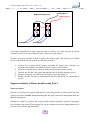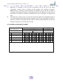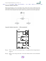
1
Design and Applied Technology (Secondary 4 - 6)
Design and Applied Technology (Secondary 4 - 6)
Design and Applied Technology
(Secondary 4 – 6)
Elective Module 1
Automation
[Teacher’s Guide]
Resource Materials Series
In Support of the Design and Applied Technology Curriculum
(S4 –6)
Technology Education Section
Curriculum Development Institute
Education Bureau
The Government of the HKSAR
Developed by
Institute of Professional Education
And Knowledge (PEAK)
Vocational Training Council
Design and Applied Technology (Secondary 4 - 6)
Technology Education Section
Curriculum Development Institute
Education Bureau
The Government of the Hong Kong Special Administrative Region
Room W101, 1/F, West Block, Kowloon Tong Education Service Centre,
19 Suffolk Road, Kowloon Tong, Hong Kong
Reprinted with minor amendments 2010
Project Advisor:
Mr. Eric Liu
(Head, Department of Multimedia and Internet Technology, IVE/Tsing Yi)
Author:
Mr. Li Yu Wai
(Design and Technology Teacher)
Project Coordinators:
Mr. Li Yat Chuen
Mr. Tsang Siu Wah
(Senior Training Consultant, PEAK/VTC)
(Training Consultant, PEAK/VTC)
The copyright of the materials in this package, other than those listed in the Acknowledgments section and the
photographs mentioned there, belongs to the Education Bureau of
the Government of the Hong Kong Special Administrative Region.
© Copyright 2009
Duplication of materials in this package other than those listed in the Acknowledgements section may be used
freely for non-profit making educational purposes only. In all cases, proper acknowledgements should be made.
Otherwise, all rights are reserved, and no part of these materials may be reproduced, stored in a retrieval system
or transmitted in any form or by any means without the prior permission of the Education Bureau of
the Government of the Hong Kong Special Administrative Region.
Design and Applied Technology (Secondary 4 - 6)
PREFACE
A set of curriculum resource materials is developed by the Technology Education Section of
Curriculum Development Institute, Education Bureau for the implementation of the Design
and Applied Technology (Secondary 4-6) curriculum in schools.
The aim of the resource materials is to provide information on the Compulsory and Elective
Part of the DAT (Secondary 4-6) to support the implementation of the curriculum.
The
resource materials consist of teacher’s guides and student’s learning resource materials of
each Strand and Module of the DAT (Secondary 4-6) arranged in eight folders.
All comments and suggestions related to the resource materials may be sent to:
Chief Curriculum Development Officer (Technology Education)
Technology Education Section
Curriculum Development Institute
Education Bureau
Room W101, West Block, 19 Suffolk Road
Kowloon Tong
Hong Kong
Design and Applied Technology (Secondary 4 - 6)
CONTENTS
Sections
1.
Principles
1
2.
Concept Map
3
3.
Key Concepts
4
4.
Teaching Schemes
5
5.
Sample Lesson Plans
9
6.
Teaching Notes
23
7.
Teachers’ Notes for Theme-based Learning Tasks
64
8.
Teachers’ Notes for Assessment Tasks
70
9.
References
76
10.
Acknowledgements
80
*
“Chapters”
refer to the Chapters in the Learning Resource Materials of this Module
Design and Applied Technology (Secondary 4 - 6)
SECTION 1 – PRINCIPLES
DEVELOPMENT OF LEARNING AND TEACHING MATERIALS
This module is composed of four major chapters which include Basics of Control System,
Pneumatics, Programmable Control Systems and Robotics according to the Design and
Applied Technology Curriculum and Assessment Guide (Secondary 4 – 6). Based on the total
allocated lesson time to DAT is 270 hours, not less than 80 hours of which will be dedicated
to coursework. A rough estimation of time allocated for an optional module, such as
Automation, is about 70 hours.
Coursework refers to the recommended learning activities included in the Theme-based
Learning Tasks and Assessment Tasks of the Students Resource Materials. The coursework is
the essential constituent in the module for students to apply their acquired scientific and
technological knowledge to solve authentic problems. It involves extensive readings of
relevant information and a number of self-directed learning outside the classroom. Therefore,
students are expected to have independent learning in addition to the scheduled hours of
coursework.
It is recommended to adopt teaching aids or learning kits to demonstrate concepts in some of
the topics, such as PLCs, pneumatics and electro-pneumatic. We have no preferences or
implications to use any specific hardware, kits and equipments available in the market. DAT
teachers are free to adopt any teaching aids to deploy their lessons in accordance to their
professional knowledge and their students’ needs as long as the key concepts and the learning
objectives are met.
Examples of local contexts, which are supposed to be more familiar to our students, are
recommended to our daily classroom teaching, At the same time, students are encouraged to
keep their eyes open to the emerging of state-of-art technology in global sense.
CURRICULUM PLANNING
The arrangement of four chapters does not imply the teaching sequences, except chapter 1 Basics of Control System is recommended to be taught first as a foundation to build up
concepts of control theory.
Students are recommended to complete one chapter fully before going to the next. It includes
the completion of all after chapter quizzes, the relevant theme-based learning tasks and
assessment tasks. The availability of teaching aids and the readiness of teachers/students can
be the factors affecting the teaching sequences and schedules..
1
Design and Applied Technology (Secondary 4 - 6)
S4
Compulsory part
S5
Automation: Topic 1, Topic 2
S6
Table 1
Coursework
Automation: Topic 3, Topic 4
Suggested Teaching schedule for the Automation module
LEARNING AND TEACHING
DAT is one of the subjects in the Key Learning Area of Technology Education, therefore,
hands-on and experiential learning activities are the essentials of this subject. The
theme-based learning tasks are the main features of this subject. They are also the strategies
for catering learners’ diversity, as the learning outcomes of these activities are open to the
students’ ability. Talented students can innovate or even invent a new product whilst mediocre
or less-able students can also make their own technological artifacts under the guidance of
teachers and the availability of resources.
The “Stop and Think” in the students resources packages can serve as a tool to assess how
well students are learning during the lessons (formative assessment) and as a basis to provoke
classroom interaction. The “Stop and Think” is recommended for probing questions to
promote learning atmosphere.
2
Design and Applied Technology (Secondary 4 - 6)
SECTION 2 – CONCEPT MAP
3
Design and Applied Technology (Secondary 4 - 6)
SECTION 3 – KEY CONCEPTS
CHAPTER 1
BASIC OF CONTROL SYSTEM
The key concepts of this chapter employ daily household electrical appliances as examples for
learning fundamental control theory, such as the temperature control in oven, the fluid level
control in water tank, the temperature and humidity control in air conditioner, the traffic
control in traffic light and the sequential logic control in washing machine, etc. These
examples are used to illustrate the concepts of open-loop, closed-loop, sequential and logical
control, etc. Students are expected to understand some terminology in the discipline of
Automation, such as open-loop, closed-loop, proportional band, offset, equilibrium, feedback,
error and so on. After completing this chapter, students should become confident in appraising
basic control systems.
CHAPTER 2
PNEUMATICS
The key concepts of this topic range from understanding pneumatic basics and components to
the application of pneumatics and electro-pneumatic circuits in industrial settings. Practicing
DAT teachers should have been familiarized with the topic of pneumatics, therefore, attention
should be given to solenoid valve and the hands-on activities of electro-pneumatics circuitry.
More practical industrial applications are included for senior secondary students.
CHAPTER 3
PROGRAMMABLE CONTROL SYSTEMS
The key concepts of this chapter are the application of Programmable Logic Controller (PLC),
ladder logic diagram, Programmable Interfacing Controller (PIC) and some electrical
actuators. Focus should be given to the understanding of ladder logic and the programming of
PLCs. The introduction of PIC in this chapter is to provide students with the basics of
interfacing with other electric components which will be very useful for preparing their final
year project.
CHAPTER 4
ROBOTICS
The key concepts of this topic are the understanding of robotic basics and their applications.
The classification of robots, the drive systems, control systems and the end-effectors designs
are the topics to be addressed. After taking this chapter, students are expected to appraise a
robotic system. Besides the classroom teaching, it is highly recommended to arrange a field
trip to local industry or tertiary education laboratory to let students have a look at an industrial
robotic arm.
4
Design and Applied Technology (Secondary 4 - 6)
SECTION 4 – TEACHING SCHEMES
OVERALL ARRANGEMENT
A total of 70 hours are allocated to cover this module. Out of these 70 hours, and 35 hours are
recommended for coursework. Teachers can fully utilize the schedule for coursework to
conduct learning activities, such as cross-curricular or integrated design project(s). An
estimation of number of hours required for each chapter in this module is as follows:
1st Term
S4
S5
S6
2nd Term
Compulsory Core Module
Chapter 1: Basics of Control System
Chapter 2: Pneumatics
Topic 1.1 Open-Loop, Closed-Loop and Sequential
Topic 2.1 Pressure
Topic 2.2 Pneumatics Components and Symbols
control systems
Topic 1.2 System and Sub-systems
Topic 2.3 Understanding Pneumatic Components
Topic 1.3 Operation of washing machine
Topic 2.4 Pneumatic Circuitry
Topic 1.4 Operation of traffic lights
Topic 2.5 Electro-pneumatic Systems
Topic 1.5 Control of fluid level in a tank
Assessment Tasks – Question 2 -7 (Pneumatics)
Topic 1.6 Application of control systems in a buggy
Topic 1.7 Application of control systems in an air
conditioner
Theme-based Learning Task (TLT) 1 – Practical
Design appreciation - Case Study of Intelligent Fire
Alarm System.
Assessment Tasks – Question 1: (Basics of Control
Systems)
Chapter 4: Robotics
Chapter 3: Programmable control systems
Topic 3.1 What is Programmable Logic Controller Topic 4.1 Definition of Robots
(PLC)?
Topic 4.2 Mechanical structure of Industrial
Topic 3.2 Programming the PLC.
Robotic Arms
Topic 3.3 Application of ladder Logic Diagram
Topic 4.3 Robot Anatomy
Topic 3.4 Programmable Interface Controller
Topic 4.4 Robot Control Systems
Topic 3.5 Stepper Motor and Servomotor.
Topic 4.5 Application of Robots
Theme-based Learning Task 3 – Design and Make
Theme-based Learning Task 2 – Hands-on Activity – Project - Pipe Cleaning/Inspection Robot
Controlling an automated traffic lights using
Theme-based Learning Task 4 – Mars
programmable logic controller
Exploration – Design an innovative End-effector
Assessment Tasks 8-10 (PLC)
for Mars Lander
Table 2
Teaching scheme in senior secondary level 5 to 6
5
Design and Applied Technology (Secondary 4 - 6)
DETAILED SCHEMES
Chapter 1: Basics of Control System
No.
Topic
Hrs
Type of delivery
T
C
Remarks
1
Topic 1.1 Open-Loop, Closed-Loop
and Sequential control systems
1
0
RM in classroom
2
Topic 1.2 System and Sub-systems
1
0
RM in classroom
3
Topic 1.3 Operation of washing
machine
1
0
RM in classroom
4
Topic 1.4 Operation of traffic lights
1
0
RM in classroom
5
Topic 1.5 Control of fluid level in a
tank
1
0
RM in classroom
6
Topic 1.6 Application of control
systems in a buggy
1
0
RM in classroom
7
Topic 1.7 Application of control
systems in an air conditioner
2
0
RM in classroom
8
TLT 1 – Practical Design
appreciation - Case Study of
Intelligent Fire Alarm System.
0
6
RM in classroom
Graded
assignment
9
Assessment Tasks – Question 1:
(Basics of Control Systems)
0
2
RM/HO/DM in special
room
Graded
assignment
Total Hours
8
8
Table 3
Detailed Plan for delivery of Chapter 1
Chapter 2: Pneumatics
No.
Topic
Hrs
T
Type of delivery
C
1
Topic 2.1 Pressure
2
0
RM in classroom
2
Topic 2.2 Pneumatics Components and
Symbols
2
0
RM in classroom
3
Topic 2.3
Components
2
0
RM in classroom
4
Topic 2.4 Pneumatic Circuitry
3
0
RM in classroom
5
Topic 2.5 Electro-pneumatic Systems
3
0
RM in classroom
6
Quizzes
Assessment Tasks – Question 2 -7
0
4
RM/HO/DM
special room
Total Hours
12
4
Understanding
Table 4
Pneumatic
Detailed Plan for delivery of Chapter 2
6
Remarks
in
Graded
assignment,
Design and Applied Technology (Secondary 4 - 6)
Chapter 3: Programmable Control Systems
No.
Topic
Hrs
T
Type of delivery
Remarks
C
1
Topic 3.1 What is Programmable
logic controller(PLC)?
1
0
RM in classroom
2
Topic 3.2 Programming the PLC.
2
0
RM in classroom
3
Topic 3.3 Application of ladder
Logic Diagram
3
0
RM in classroom
4
Topic 3.4 Programmable Interface
Controller
3
0
RM/HO
special room
5
Topic 3.5 Stepper Motor and
Servomotor.
1
0
RM in classroom
6
TLT 2 – Hands-on Activity –
Controlling an automated traffic
lights using programmable logic
controller
0
3
RM/HO/DM
special room
in
Graded assignment
7
Quizzes
Assessment Tasks 8-10
(Electro-pneumatic/PLC)
0
4
RM/HO/DM
special room
in
Graded assignment
Total Hours
10
9
Table 5
in
Detailed Plan for delivery of Chapter 3
Chapter 4: Robotics
No.
Topic
Hrs
T
1
Type of delivery
C
0
RM in classroom
1
Topic 4.1 Definition of Robots
2
Topic 4.2 Mechanical structure of
Industrial Robotic Arms
1
0
RM in classroom
3
Topic 4.3 Robot Anatomy
1
0
RM in classroom
4
Topic 4.4 Robot Control Systems
1
0
RM in classroom
5
Topic 4.5 Application of Robots
1
0
RM in classroom
6
Quizzes
Theme-based learning Task 3 –
Design and Make Project - Pipe
Cleaning/Inspection Robot
Theme-based learning Task 4 –
Mars Exploration – Design an
innovative End-effector for Mars
Lander
0
13
RM/HO/DM
special room
5
Total Hours
Table 6
in
Remarks
Graded assignment
14
Detailed Plan for delivery of Chapter 4
7
Design and Applied Technology (Secondary 4 - 6)
Legends:
T: Teaching
C: Coursework
Q: Quiz
TLT: Theme-based Learning Task
RM: Resource Materials
DM: Demonstration
HO: Hands-on Activity
CS: Case Study
EX: Exercises/Practical Task
DP: Design Project
8
Design and Applied Technology (Secondary 4 - 6)
SECTION 5 – SAMPLE LESSON PLANS
TEACHING SCHEME (SAMPLE 1)
Design and make Project
: (1) Pipe Cleaning Robot or (2) Pipe Inspection Robot
Aims and Objectives:
Students will become an expert in design and development process, micro-controller
application, interfacing techniques and mechanical design through this design project.
Students can also gain other learning experiences and develop generic skills by the end of this
learning task.
Learning Task Planning Philosophy:
1.
2.
3.
Adopt Life Wide Learning (LWL) approach to provide students with real life scenario
and authentic learning experience in developing their dedicated robots.
Students can develop their dedicated robots by system integration approach and based on
the school resources. It eliminates the chance of failing the project for the low achieving
students.
Adopt the Design project approach and promote collaborative learning throughout the
whole robot development process.
Teaching Strategies
1.
2.
Teacher plays the role as a consultant, facilitator, information and resources provider
throughout the teaching and learning process.
Teacher is responsible for the project management and provides appropriate
technologies and knowledge for students to tackle the design challenge.
Learning Strategies
1.
2.
Diversified learning strategies, such as writing journals (online blogs), presentations
(group presentation), demonstrations (open competition), reading to learn (self-directed
reading) and enterprise activities (mini-exhibition in campus) are interweaved
throughout the whole learning tasks.
Students are provided chances to develop their generic skills and solve real life problem.
They are expected to pursuit their learning outside the classroom.
9
Design and Applied Technology (Secondary 4 - 6)
Period Allocation
No. of
periods:
12 periods
No. of hours: 22 hours.
Level
NSS-2
No. of Periods per
cycle:
Duration of each
period:
Theme:
1 single period, 2 double
periods
Teacher to students ratio: 1 :
40 mins.
Place:
ITLC and/or DAT room
Design and Make Project
Topics:
Robotics
40
Teaching Scheme
Period
Teaching Activities
Learning Activities
Teaching and learning
Resources
Assessment/
Competency Level
01
Project Briefing
1. Teacher explains the project
requirements and overall
schedule.
2. A pipe test rig is provided for
demonstration. Different types of
locomotion and cleaning devices
are provided for promoting
students’ creativity.
Students should
1. Write a Design Brief.
2. Compare the advantages and disadvantage of
different locomotive types and their fitness for the
design purpose.
3. Form a group of 3 for the design project.
- A pipe test-rig for
demonstration
- Some locomotive devices,
such as wheel-drive and
belt-drive for
demonstration.
- Compare the
advantages and
disadvantages of
different locomotion.
- Complete a reflection
journal in the
Interactive Learning
ePlatform.
- Write a Design Brief.
Students should
1. Prepare comprehensive Mindmap,
2. Understand design factors and considerations
3. Understand assessment criteria for the peer
evaluation
4. Prepare group verbal presentation
- Large colored drawing
papers, sign pens and
color pens.
02
Concepts Building and Group
Presentation
1. Teacher illustrates Mindmap
formulation and requirement of
group presentation
2. Teacher explains the method of
evaluation and assessment
3. Teacher takes a facilitator role for
- Submission of
Mindmap
- Peer Evaluation
- Prepare r group
presentation
10
Design and Applied Technology (Secondary 4 - 6)
Period
Teaching Activities
Learning Activities
Teaching and learning
Resources
Assessment/
Competency Level
the group discussion
Group Verbal Presentation
1. Teacher conducts the student
group presentation.
Students should
1. Conduct 10 minutes group presentation.
2. Deploy a well-organized and good allocation
of work.
- Microphone and
networked computer may
be required.
- Video-taking of
presentations
- Posted on web for
sharing
- Conduct group
presentation
- assess the
presentations
Formulation of Possible Preliminary
Designs
3. Teacher clearly states the
requirement of the design
drawings
4. Teacher demonstrates some
essential drawing and rendering
techniques
5. Teacher provides consultation to
students during the brainstorming
stage
Students should
1. Propose 3 possible design solutions
2. Prepare at least 3 annotated sketches for
demonstration
- A3 drawing papers,
pencils and colored
pencils.
- Demonstrate drawing
techniques.
- Digitalize the design
sketches for portfolios
- Submit 3 annotated
design sketches
Computer Control of Locomotive
Drive
1. Teacher demonstrates motor
directional and speed control.
2. Teacher explains underlying
principle, advantages and
disadvantage of motor controls.
Students should
1. Understand the differences of DC and servo
motors
2. Transfer the control technologies of DC
motors and servo motors to designed robots.
- Apply different types of
motor circuit boards,
gearbox and mobile
platform
- Complete a
reflection journal in
the e-Learning
Platform.
- Self-directed
readings of data
sheets, websites,
reference materials
03
04
05
11
- Conduct selection of
design process
- Provides feedback
Design and Applied Technology (Secondary 4 - 6)
Period
Teaching Activities
Learning Activities
Teaching and learning
Resources
Assessment/
Competency Level
3. Teacher demonstrates DC motor
and servomotor control
Students should
1. Understand the theory of signal transfer
2. Apply the signal transfer technologies to their
designed robots
- Video signal transfer kits
for demonstration
06
Demonstration of Video
transmission and interfacing with
computer
1. Teacher demonstrates the wired
and wireless transmission of
video signal to the computer.
2. Teacher explains the basic
principle of signal transfer.
- Complete a reflection
journal
- Self-directed
readings of data
sheets, websites,
reference materials.
Students should
1. Understand the interfacing
2. Transfer the sensors interfacing technologies
to their designed robots.
- Demonstration kits of
photo resistors,
near-infrared proximity
sensors, micro switches,
mercury tilt sensors and
sonar transducers.
- Complete a reflection
07
Demonstration of Interfacing
Sensors
1. Teacher uses teaching kits to
demonstrate the interfacing of
different sensors that include
photo resistors, near-infrared
proximity sensors, micro
switches, mercury tilt sensors
and sonar transducers.
2. Teacher explains the basic
principles of different sensors
12
journal
- Self-directed
readings of data
sheets, websites,
reference materials.
Design and Applied Technology (Secondary 4 - 6)
Teaching and learning
Resources
Assessment/
Competency Level
Students should
1. Use CAD to prepare paper template with
markings that indicate all cuts, holes and
bends to be made.
2. Be able to use marking-out tools and
techniques.
3. Be able to use basic hand tools and sheet
metalworking techniques.
- Basic workshop tools,
machinery and
equipment.
- Computer with 2D or 3D
CAD program.
- Wheels, tank-drive belts,
spokes, shafts, rollers
and bearings.
- Submit paper
template prepared by
CAD
- Complete a reflection
journal
Making of Application Devices
Prototypes – Pipe Cleaning or Pipe
Inspection Device
1. Students use exploratory
approach to build their
application devices.
2. Teacher provides consultation to
students.
Students should
1. Apply their knowledge to build their
application devices to meet the designated
purpose.
2. Decide what sensors to be included in their
application devices.
3. Prepare a Bill of Materials (BOM).
4. Conduct Functionality Test and record the
results.
- Provide electronic and
electrical components,
such as motor control
boards, DC and servo
motors, battery supplies,
DC supplies, gearboxes,
electric wires, signaling
wires and soldering kits.
- Provide basic workshop
consumables, tools,
machineries and
equipment.
- Build a workable
application devices
prototype.
- Prepare a Bill of
Materials (BOM)
- Complete a
reflection journal
Final Assembly
1. Students assemble the
application device onto the
mobile platform and perform the
final testing.
2. Students fine-tune their robots
Students should
1. Test their robots in the test rig.
2. Prepare their final presentation.
- Video-taking of process.
- Networked PC with
Bloggers in school
Intranet.
- Students can write
group blog in school
intranet for sharing
Period
Teaching Activities
08
Making of Mobile Platform
1. Teacher demonstrates the
techniques of marking-out and
fabrication of sheet metal and
acrylics.
2. Teacher encourages students to
perform testing
3. Teacher allows students evaluate
and redesign their idea
09
10
Learning Activities
13
Design and Applied Technology (Secondary 4 - 6)
Period
Teaching Activities
Learning Activities
Teaching and learning
Resources
Assessment/
Competency Level
Video recorder
Networked computer
Wireless microphone
Assessment and Scores
sheets for judge panel
- Submit all
presentation
materials
- Teachers assess and
evaluate final
submission
3. Teacher assesses the robots
performance and provide
feedback
11
Final Presentation and Open
Competition
1. Teacher arranges an open event
and invites principal, teachers,
parents and students to form the
judge panel to assess group
presentation and demonstration.
Students should
1. Prepare a 15 - 20 minutes presentation by
webpage, blog or Powerpoint
demonstration.
2. Conduct rehearsal before final presentation.
-
12
Exhibition
1. Teacher organizes a
mini-exhibition in school
campus and asks students to be
the interpreters for their own
robots.
Students should
1. Form an editorial committee for publishing
the exhibition brochure
2. Form an organizing committee to coordinate
all the logistics and exhibition matters.
3. Be the interpreters for their exhibition booths.
- Networked computer
- Video recorder.
- Bench and booths
- Complete a
reflection journal
- Prepare and publish
exhibition
brochures.
Suggested Follow-Up Activities and Assignments
This learning task has adopted the Wide Life Learning approach, the final learning outcomes – the pipe cleaning robots or the pipe inspection
robots will be deployed in the events of presentation, competition and exhibition. Students have a lot of opportunities to develop their generic
skills and work in an authentic learning environment. They will gain experience through organizing competition and exhibition that will involve
a lot of logistics and liaison works. Students have the opportunities to train their interpersonal and communication skills. They also have to
commercialize their robotics through the Web and blogs. In all these senses, DAT teachers have a lot of opportunities to invite cross-curricula
projects with other subjects, such as ICT, languages, Visual Arts, BAFS, Travel and Tourism, etc.
14
Design and Applied Technology (Secondary 4 - 6)
Suggested Cross-Curricula Teaching and Learning Activities
ICT
Languages
VA
DAT
DAT
Design a Website with How to use Blogger
enquiry and shopping
cart function
Verbal Presentation
How to write press
release
Design and decorate
the exhibition venue
DAT
DAT
How to write exhibition How to write journal
How to write blog
brochure
Graphical design of the Design the exhibition
Website
brochure
Marketing
strategy,
budgeting and pricing
BAFS
TT
DAT
Organize field trip to Promotion
exhibition centre and advertising
design office
15
and Co-organizer
of
exhibition and train
the promoters
Design and Applied Technology (Secondary 4 - 6)
MODULE 1: AUTOMATION TEACHING SCHEME (SAMPLE 2)
Chapter 1 : Basics Of Control System
Aims and Objectives:
Students will be given an introduction of what is/are control or control systems about.
Students should have the necessary terminology and knowledge in analysis control systems
after completion of this chapter. Students should be able to understand the following concepts:
open-Loop and closed-Loop control, timing diagram, state/output table, equilibrium and
proportional band. With the supplementary notes from the teachers’ guide, more able students
can be exposed to the concepts of digital signal processing and PID control which seem to be
the fundamental for pursuing further study of control engineering.
Teaching Strategies
1. Teacher can conduct lecture and provide demonstration to deliver the concepts of control
systems as students need to have fundamental knowledge of control theory.
2. Teacher should take real-life example or artifacts to explain the concepts of control theory.
For example, washing machine, air-conditioner and buggy can be adopted for
demonstration and interactive learning activities.
Learning Strategies
1. Students should carry out group discussion to clarify and consolidate the concepts taught
in this chapter. It is important to have clear concepts before proceeding further to the
subsequent chapters.
2. Students should take the “Stop and Think” and the assessment activities to gain some
hands-on activities in studying the control systems.
Period Allocation
No. of
periods:
No. of
hours:
Level
6 periods
8 hours.
NSS-2
No. of Periods
per cycle :
Duration of
each period:
Theme:
2 double
periods
80 mins.
Teacher to
students ratio:
Place:
Classroom
Basics of
Control Systems
Topics:
Control Theory
16
1
:
40
Design and Applied Technology (Secondary 4 - 6)
TEACHING SCHEME
and
learning Assessment/
Competency Level
Teaching Activities
1. Worksheet
2. Q&A
3. Small group
discussion
4. Homework
01
Lecture and Demonstration
1. Explain the concepts of open-loop
and closed-loop control systems.
(Topic 1.1)
2. Explain the concepts of system and
subsystem (Topic 1.2)
3. Explain the concepts of DSP as
supplementary notes (optional)
4. Explain the washing machine
operation (Topic 1.3)
5. Introduce the Assessment Task
Question1.
- Daily examples found in the
campus, such as
air-conditioner,
can-dispenser.
- Study of a washing machine
in Technology and Living
room; or
- A video clip showing a
typical operation of washing
machine.
- Students can clearly define the
concepts.
- Students give examples to
these concepts
- Complete the assessment task
Question 1
1. Classroom discussion
02
Lecture
1. Provide answer and conclusion to
the assessment.
- Suggested answer in the
teacher guide
- Students understand the
assessment.
- Do the correction
Lecture and Demonstration
1. Level control in fluid tank (Topic
1.5)
1. Q&A
2. Classroom discussion
- Take toilet bowl water tank
as an analogue example.
- Students understand the
concepts of setpoint,
proportional band and offset in
control theory.
Lecture and Demonstration
1. Control system in buggy
(Topic 1.6)
1. Hands-on activities
(if hardware
available)
- Electromechanical buggy (if
any)
- Students understand the
control logic of buggy control
and the use of electrical time
delay in control.
03
04
Learning Activities
Teaching
Resources
Period
17
Design and Applied Technology (Secondary 4 - 6)
Period
Teaching Activities
Learning Activities
05
1. Q&A
Lecture
1. Temperature and humidity control in 2. Classroom discussion
air-conditioner
(Topic 1.7)
06
Lecture
1. 1. Control systems types: ON/OFF,
Proportional, PID control
(optional).
1. Q&A
2. Classroom and Small
group discussion
18
Teaching
Resources
and
learning Assessment/
Competency Level
- Take an air-conditioner in
classroom as an example.
- Student should understand the
concepts of control variables
and state/output.
- Supplementary notes in
Teacher guide
- Student should understand the
level and characteristics of
these control types.
Design and Applied Technology (Secondary 4 - 6)
MODULE 1: AUTOMATION TEACHING SCHEME (SAMPLE 3)
Chapters 2 : Pneumatics
Aims and Objectives:
Students should have an understanding of Pneumatics symbols, components and circuitry
after taking this chapter. A scientific definition of air pressure will be included at the early
section. Electro-pneumatics will be taught in this chapter that will also be the fundamental
knowledge for the PLC in chapter 3.
Students can gain some practical and engineering know-how in the application of Pneumatics
to tackle some industrial problems.
Teaching Strategies
1. Teacher plays the role as an instructor if there are pneumatics kits available for practical
activities.
2. Teacher can provide worksheets to assess students’ understanding of theory and practical
tasks.
3. Teacher can explain the mechanical structure and principle of valves as supplementary
information to arouse the interests of students.
Learning Strategies
1. Small group discussion, quiz and verbal presentation will be effective ways of
collaborative learning and consolidation of knowledge.
2. Students should spend times to conduct extensive readings of magazines, books and
articles relevant to this topic to build up a strong foundation for their further studying.
Period Allocation
No. of
periods:
No. of
hours:
Level
9 periods
12 hours.
NSS-2
No. of Periods 1 double periods
per cycle :
80 mins.
Duration of
each period:
Pneumatics
Theme:
19
1: 40
Teacher to
students ratio:
ITLC and/or
Place:
DAT room
Theory and
Topics:
practical
Design and Applied Technology (Secondary 4 - 6)
Teaching Scheme
Period
Teaching Activities
Learning
Activities
Teaching and learning Resources
Assessment/
Competency Level
01
Lecture
1. Introduction of air pressure and air
preparation of Pneumatics
(Topic 2.1)
1. Q&A
2. Demo board
- Real objects and chart can be
used for explanation
- Students can clearly
define the various
systems of pressure
02
Lecture
1. Explanation of Pneumatics circuit
symbols (Topic 2.2 & 2.3)
Lecture and Demonstration
1. Explanation of basic Pneumatics
circuitry (Topic 2.4)
1. Q&A
2. Worksheets
- Magnetic symbols for
explanation
- Students can identify
different types of
symbols
1. Q&A
2. Practical
- Magnetic symbols for
explanation
- Authentic demonstration (if
Pneumatics kit available)
- Students can design and
draw simple Pneumatics
circuits.
03
04 – 05
Assessment
1. Explain the Assessment questions
from 2 to 7
2. Feedback and suggested answers
1. Classroom and
2. small group
discussion
Magnetic symbols for explanation
Authentic demonstration if
Pneumatics kit available
Students can design and
complete the tasks on their
own
06 – 07
Lecture
1. Explanation of solenoid valves and
Electro-pneumatics
(Topic 2.4)
1. Q&A
2. Demo board
3. Classroom
discussion
Magnetic symbols for explanation
Authentic demonstration if
Pneumatics kit available
Students can understand
the operation of solenoid
valve
08 - 09
Lecture
1. Introduce 3 cases of industrial
applications
(Topic 2.5)
1. Classroom
discussion
Magnetic symbols for explanation
Field trip to local industry or
tertiary laboratory can be arranged
Students can understand
the industrial application of
Pneumatics and
Electro-pneumatics
20
Design and Applied Technology (Secondary 4 - 6)
MODULE 1: AUTOMATION TEACHING SCHEME (SAMPLE 4)
Chapters 3 : Programmable Control Systems
Aims and Objectives:
Students should gain fundamental knowledge of Programmable Control System in this chapter.
Students should acquire the concepts and working principle of Programmable Logic
Controller. Ladder logics and motor control systems are also introduced in this chapter.
Students should have some practical activities of tackling control design problems after
completion of this chapter.
Teaching Strategies
1. Teacher plays the role as an instructor if there are PLC kits available for practical
activities.
2. Teacher can provide some worksheets to assess students’ understanding of ladder logic
and PLC programming.
Learning Strategies
1. Small group discussion, quiz and verbal presentation will be very effective ways of
collaborative learning and consolidation of knowledge.
2. Students should have hands-on activities in PLC programming and control if hardware
kits are available for better understanding of this topic.
3. Students are encouraged to tackle the Thematic Learning Task 4 after taking this chapter.
Period Allocation
No. of
periods:
8 periods No. of Periods
per cycle :
No. of
hours:
10 hours. Duration of
each period:
Level
NSS-3
Theme:
1 double periods
1
Teacher to
students ratio:
:
40
80 mins.
Place:
ITLC and/or
DAT room
Programmable
Logic Controller
Topics:
PLCs and
Ladder Logics
21
Design and Applied Technology (Secondary 4 - 6)
TEACHING SCHEME
Period
01
02
03
04
05 – 06
07 - 08
Teaching Activities
Learning Activities
Teaching and learning Resources
Assessment/
Competency Level
Lecture
1. Introduction of PLC theory and working
principles (Topic 3.1)
1. Q&A
2. Stop and Think
- Resources package
- Students can clearly define
the various parts of PLCs
Lecture and demonstration
1. Explanation of PLC control theory and
programming (Topic 3.2)
1. Q&A
2. Classroom
discussion
- PLC simulation software should be
used for demonstration (Freeware
may be available)
- Students should fully
understand the PLC logic and
programming.
Lecture and demonstration
1. Explanation of ladder logic
(Topic 3.3)
1. Classroom
discussion
- Magnetic symbols or simulation
program should be used.
- Students should fully
understand the ladder logic
and circuit.
Lecture
1. Explanation of stepping motors theory and
H-bridge control of DC motors (Topic 3.5)
1. Q&A
2. Demo board
- Real motors and control circuits for
explanation
- Students can describe the
working principle.
Theme-based Learning Task 2
Hands-on activity – Controlling an automated
traffic lights using PLC
1. Hands-on
activities
- PLC kits should be available for
hands-on practice
- Students can complete the
design on their own
Assessment Tasks
1. Question 8-10, Programmable Logic
Controller
1. Hands-on
activities
- PLC kits should be available for
hands-on practice
- Students can complete the
design on their own
22
Design and Applied Technology (Secondary 4 - 6)
SECTION 6 – TEACHING NOTES
* Chapters refer to the chapters in the Learning Resource Materials of this Module
Introduction
This module aims at providing students with broader sense of integrated knowledge to
understand automated control systems. This module is composed of four chapters that
include the concepts of Control System Basics, the know-how of Pneumatics cum
Electro-pneumatics, the application of Programmable Control Systems and Robotics.
The resources packages consist of student’s notes, STOP and THINK, exercise, examples,
quizzes, four thematic learning tasks and assessments. The students’ notes provide the
theoretical background for the concept building, whilst the four thematic learning tasks are
used for the practicality and cater for the learning diversities.
The four chapters are complementary and supplementary to one another. Chapter 1
underlies the principle of sequential control, closed-loop systems and sub-systems. This
chapter will use the operation of washing machine, buggy, air-conditioner and production line
as an elaboration. Chapter 2 will illustrate the application of pneumatics and
electro-pneumatics systems. It somehow involves the PLCs, which will be discussed in
chapter 3, for the control of electro-pneumatic system. In chapter 4, it deals with the basic of
robotics in a qualitative approach. The examples of using Programmable Interface Controller
are also introduced in chapter 4.
After completing this module, students should have confidence and competence to solve
technical problems or carry out design projects with demand of automatic control, and be able
to solve problems in a system approach.
TEACHER NOTES : CHAPTER 1 BASICS OF CONTROL SYSTEM
S T O P
A N D
T H I N K
1.
Suggest any disadvantage of this type of temperature and humidity control?
2.
Suggest any method that can improve this overall control system?
23
Design and Applied Technology (Secondary 4 - 6)
Suggested Answers
1.
When the control value is derivated (over or lower) from the set point, the actuator, such
as the heating coil and the humidifier, will be turned on and off frequently. The problem
will be in two folds: a. the frequent switching will cause the mechanical parts, such as the
pump, to wear out or damage quickly and the frequent switching of electrical power will
impose electrical and thermal stress to the electrical components; b. the response is so
often and sensitive that it will cause overshooting and difficulties to maintain the state of
equilibrium.
2.
Adopt the fuzzy logic so that the control will no longer be just an on and off action or use
Proportional, Integral and Derivative controller (PID) so that the overshooting can be
minimized.
Teacher should remind their students that the System and Sub-systems in section are
introduced by a system engineering approach. This means that it is interpreted
macroscopically in a boarder sense. Take the China Manned Spacecraft Shenzhou 7 as an
example, the whole project is regarded as a Manned Aerospace System, however, it is
composed of 7 major sub-systems, such as Landing Ground Sub-system, Astronauts
Sub-system and Manned Spacecraft Sub-systems, etc. Each Sub-system are further
decomposed into a number of sub-systems in different level of scale, and finally down to a
component level.
In another sense, sub-system can be explained in a daily example, such as an electric
toothbrush that is composed of a power and charging sub-system, cleaning sub-system, drive
sub-system and the control sub-system. The cleaning sub-system can be as simple as the
mechanism of changing the brush head, the drive sub-system can be as simple as a DC motor
whilst the control sub-system may be just a push button.
24
Design and Applied Technology (Secondary 4 - 6)
How do Temperature Controllers work?
The example of air conditioner is only a simplified system used to illustrate the concept of
temperature control. However, in practice, the situation is a bit more complicated.
Here is an example of industrial application: A temperature control system relies upon a controller,
which accepts a temperature sensor such as a thermocouple or RTD as input. It compares the actual
temperature to the desired control temperature, or setpoint, and provides an output to a control element.
The controller is one part of the entire control system, and the whole system should be analyzed in
selecting the proper controller. The following items should be considered when selecting a controller:
1.
2.
3.
4.
Type of input sensor such as thermocouple, RTD and temperature range
Type of output required (electromechanical relay, SSR, analog output)
Control algorithm needed (on/off, proportional, PID)
Number and type of outputs (heat, cool, alarm, limit)
There are three basic types of controllers: on-off, proportional and PID.
On/Off Control
An on-off controller is the simplest form of temperature control device. The output from the device is
either on or off, with no middle state. The air-conditioner example in this chapter is this type.
An on-off controller will switch the output only when the temperature crosses the setpoint. For heating
control, the output is on when the temperature is below the setpoint, and off when above the setpoint.
Since the temperature crosses the setpoint to change the output state, the process temperature will be
cycling continually, going from below setpoint to above, and back below.
In cases where this cycling occurs rapidly, and to prevent damage to contactors and valves, an on-off
differential, or “hysteresis,” is added to the controller operations. This differential requires that the
temperature exceeds setpoint by a certain amount before the output will turn off or on again.
On-off differential prevents the output from making fast, continual switching if the cycling above and
below the setpoint occurs frequently. On-off control is usually used where a precise control is not
necessary.
One special type of on-off control is used for alarm. This controller uses a latching relay, which must
be manually reset. It is also used to shut down a process when a certain temperature is reached or
danger happened.
Proportional Control
Proportional controls are designed to eliminate the cycling associated with on-off control. A
proportional controller decreases the average power supplied to the heater as the temperature
approaches setpoint. This has the effect of slowing down the heater (temperature rise) so that it will not
overshoot the setpoint, but will approach the setpoint and maintain a stable temperature.
25
Design and Applied Technology (Secondary 4 - 6)
This proportioning action can be accomplished by turning the output on and off for short time intervals.
This "time proportioning" varies with the ratio of “on” time to "off" time to control the temperature.
The proportioning action occurs within a “proportional band” around the setpoint temperature.
Outside this band, the controller functions the same as an on-off control unit and the output will either
be fully on (below the band) or fully off (above the band). However, within the band, the output is
turned on and off in the ratio of the measurement difference from the setpoint.
At the setpoint (the midpoint of the proportional band), the output on:off ratio is 1:1; that is, the
on-time and off-time are equal. If the temperature is further from the setpoint, the on - and off - times
vary in proportion to the temperature difference. If the temperature is below setpoint, the output
(heater) will be ON longer, if the temperature is too high, the output (heater) will be OFF longer.
PID Control
PID stands for Proportional, Integral, and Derivative. It is the controller designed to eliminate
the need for continuous operator attention. Cruise control in a car and a house thermostat are
common examples. The controllers are used to automatically adjust some variable to hold the
measurement (or process variable, such as water level, temperature) at the setpoint. The
setpoint is where you would like the measurement to be. Error is defined as the difference
between setpoint and measurement.
(error) = (setpoint) - (measurement)
The variable being controlled is called the manipulated variable which is usually equal to the
output of the controller. The output of PID controllers will change in response to a change in
measurement from the setpoint. Manufacturers of PID controllers use different names to
identify the three modes. These equations show the relationships:
Proportional Band
With proportional band, the controller output is proportional to the error or a change in
measurement from the setpoint.
(controller output) = (error)*100/(proportional band)
With a proportional controller offset (deviation from setpoint) is present, increasing the
controller gain will make the loop go unstable. Integral action was included in controllers to
eliminate this offset.
Integral
With integral action, the controller output is proportional to the amount of time the error is
present. Integral action eliminates offset.
Controller Output = (1/Integral) (Integral of) e(t) d(t)
26
Design and Applied Technology (Secondary 4 - 6)
Integral action can eliminate the offset. The response is oscillatory and can be stabilized by
adding derivative action. Integral action gives the controller a large gain at low frequencies
that results in eliminating offset and "beating down" load disturbances.
Derivative
With derivative action, the controller output is proportional to the rate of change of the
measurement or error. The controller output is calculated by the rate of change of the
measurement with time.
dm
CONTROLLER OUTPUT = DERIVATIVE ---dt
Where m is the measurement at time t.
Derivative action can compensate for a changing measurement. Thus derivative takes action
to inhibit more rapid changes of the measurement than proportional action. Derivative is often
used to avoid overshoot.
How to construct state diagram
State Transition Table
Input
1
0
State
S1
S1
S2
S2
S2
S1
In sequential control logic, a state transition table is usually employed to indicate the state
change. It is actually a truth table showing what will be the output state which is based on the
current state and other inputs.
In the above state transition table, the vertical dimension (first column) indicates current states
which are regarded as one of the inputs. The horizontal dimension (second and third row)
indicates the next state (first row). S1 and S2 represent the single bits “0” and “1” (two states).
If the current state of the system is in S1 (the first row) and the next input is 1, the output
state will stay in S1. If the next state is 0, the output state will transit to S2 in the third column.
If the system is in S2 as the current state and the next state is S1, the output state will remain
in S2. If the next state is in S1, the output state will transit to S1.
27
Design and Applied Technology (Secondary 4 - 6)
FURTHER EXPLANATORY NOTES
What is SSR?
SSR is the short form of Solid State Relay. It is actually not a relay at all. There is no 'relay'
present, just the electronics which does the switching.
A Solid State Relay (SSR) is an electronic switch, which unlike an electromechanical
relay, contains no moving parts. The types of SSR are photo-coupled SSR,
transformer-coupled SSR and hybrid SSR.
It works the same way as a relay. It can be used for a low voltage to switch to a higher
voltage.
What is RTD?
Resistance thermometers, also called Resistance Temperature Detectors (RTDs), are
temperature sensors. Their working principle is depending on the calibrated change in
electrical resistance of some materials with the changing temperature. The material is
commonly made of platinum and they are often called Platinum Resistance Thermometers
(PRTs). They are going to replace termocouples in many industrial applications below
600 °C.
What is “hysteresis”?
Hysteresis can be explained by the following daily examples. If you push on something, it
will yield: when you release, does it spring back completely? Most of the times it doesn't.
This phenomena is called “hysteresis”. If you put a large force on your fork while cutting a
tough piece of meat, it doesn't always return to its original shape. The term is usually
applied to magnetic materials.
Suggested answer to Quizzes of chapter 1
1.
Why automated control systems are so important in industry?
From the economical point of view, automation reduces the need for skilled labour which
usually involves higher salary. The manual works left in an automated production line only
require labour skills of lower level, such as loading and loading of parts, changing tools and
removing materials chips. This gives rise to a reduction in the labuor force in an automated
industry because fewer workers are needed for these menial tasks. The industry shifts from
the labour intensive operation to an automated machine operation, the cost for higher labuor
salary are reduced. As a result, the cost per unit of product is lower. Also, the 7 x 24 hours
non-stop operation by automated machines has maximized the throughput of the production
line, thus, the output per hour per labour input can be achieved. Also, the shortage of
appropriate skill level labour is the reason for manufacturers to adopt automation to substitute
28
Design and Applied Technology (Secondary 4 - 6)
labour. From the technical point of view, automation has no allowance for human error, such
as tiredness and absent-mindedness. It allows smooth integration with Flexible Manufacturing
System and CNC machine, such as in automotive industry. Today’s production lines require
accurate, reliable, high speed and highly repetitive processes that the manual operation seems
not capable of meeting this requirement. Automated manufacturing operation has higher
production rates than the manual operations. Automated production has a lower price and
better products. The benefits of automation also come with better company images and
maintain a competitive advantage with their customers and general public in additional to
improved quality, higher sales and better labour relation.
2.
State the differences between Open-Loop and Closed-Loop control system?
Open-Loop control is a direct and simple control system. The controller is used to send signal
to the controlled element for the desired value or setpoint, i.e. certain temperature in a room or
in an oven. However, there is no “feedback” to tell the controller that the setpoint or desired
value has been reached or not. For a closed-Loop control system, a feedback signal is returned
back to the controller to tell that the controlled value has reached the setpoint or not. The
discrepancies between the desired value and the actual value are compared to give an error
signal. The feedback signal serves a self-regulating function with a view to minimize the
range of error and get close to the setpoint. The closed-Loop control system is complex but in
a more stable controlled condition.
3.
Give one daily example on Open-Loop control system and Closed-Loop control
system? Draw the block diagrams for the examples?
Washing machine is a daily example of open-Loop control. Though, nowadays, the washing
machines have many programmed washing cycle according to the nature of fabrics, weight of
laundry and the level of cleanliness, and after the cleaning cycle there is no guarantee of the
laundry has been cleaned properly or not. Human intervention is needed. The laundry needs to
be checked by visual inspection. If it is not cleaned thoroughly the laundry needs to be
washed again. Obviously, the block diagram below is a simplified situation. The washing
machine also has a closed-Loop control sub-system inside, such as the water temperature
control system and the water level detection system.
An electric kettle is an example of closed-Loop control system. When it is set to 98oC, the
heating element is switched on to boil the water. Once the temperature is reached, the heating
element will be switched off. The temperature is continuously monitored to provide a
feedback signal to the controller. Once the measured temperature drops below the desired
temperature, the heating element will be switched again to increase the temperature to the
desired value.
29
Design and Applied Technology (Secondary 4 - 6)
4.
Suggest and name the types of sensors used in a washing machine?
Tachometer is used to measure the speed of the laundry drum; limit switch can be used to
detect the closure of door; Thermocouples or Thermistors can be used to measure the water
temperature. Thermocouple is a temperature transducer in which two dissimilar metals are
connected together as a hot junction to measure the temperature. Their electrical properties
change and generate an open-circuit voltage in related to the temperature difference. The
thermistor is a resistance thermometer and its resistance changes as a function of time. Water
level sensor with two measuring probes can be used to detect the water level and control the
water inlet and drainage.
5.
What is the meaning of setpoint?
The setpoint is the desired controlled value that the controlled element need to be maintained
during the control process, such as the preset temperature in oven or refrigerator, or the water
level in water storage tank.
6.
What is the meaning of proportional band?
Mathematically, the controlled value (output) is proportional to the error or a change in
measurement by feedback device divided by the Proportional Band.
Controlled value = Error*100/Proportional band
Physically, the proportional band is a range of output value which varies in proportional to the
feedback signal. Within the proportional band, the system is still under control and in a state
of equilibrium around the setpoint.
7.
What is the meaning of error signal?
The error signal is the measured value from the feedback sensor in a closed-Loop control
system. It is used to adjust the input value so as to keep the control system under control. If
the error signal is subtracted from the control value, it becomes the negative feedback. It
means that if the controlled value goes beyond the setpoint, the feedback signal will reduce
the input value and make the output return to its desired value. If the error signal is “added” to
the control value, it is known as the positive feedback. It will make the system go unstable
and uncontrollable from the setpoint. It is rare in application.
30
Design and Applied Technology (Secondary 4 - 6)
8.
What is the meaning of offset?
Offset is the magnitude of controlled output value from the setpoint.
9. Describe how a Resistor and Capacity (RC) circuit can function as a timer?
An analogue RC electric circuit can be used as a delay timer. A charged up capacitor will
release electricity through a parallel connected resistor when the power is off. The larger the
resistance, the longer will the capacitor take to discharge its electricity and thus can produce a
time delay effect.
10. What sensors can be used as a bump switch for an obstacle avoiding buggy?
Limit switch as an electrical on-off switch can be used as a touch sensor to detect the presence
of object. It can be triggered by depressing a button or lever to make a contact.
Proximity sensors can also be used to detect an object which is close to the sensor.
31
Design and Applied Technology (Secondary 4 - 6)
TEACHER NOTES : CHAPTER 2
S T O P
PNEUMATICS
A N D
T H I N K
Why the output pressure will increase when the consumption flow rate drops and vise
versa? Can you account for this phenomenon?
Suggested Answers
It is a scientific phenomenon and explained by the Bernoulli Theorem. It is stated that when
there is a fluid flow in a closed or open channel, the higher the velocity the lower becomes the
pressure. It is usually applied to explain the lifting force made by the aerofoil. For a daily
example, when you are standing close to the yellow line in the MTR platform, when a train is
by-passing you at a high speed, you will feel a force attracting you towards to the train. Why?
Due to the Bernoulli Theorem, there is a pressure drop caused by the high speed train and the
pressure drop generates a “suction” force to the people nearby.
S T O P
A N D
T H I N K
What will be the advantages of a combined APU ?
Suggested Answers
A combined Air Handling Unit (APU) is a modular design which is composed of
separate units of Filter, Regulator and Lubricator. It has the advantages of compact in size and
ease of replacement and maintenance. Some pneumatic system will omit the lubricator to
provide a clean air for some application, such as food, electronic or pharmacy industry. The
lubricator can easily be attached from the combined APU without too much system
configuration.
S T O P
A N D
T H I N K
Would you describe briefly the following two valves to see how much you understand at
this stage?
(a)
(b)
32
Design and Applied Technology (Secondary 4 - 6)
Suggested Answer
(a)
It is a 3/2, 3 ports and 2 positions directional valve. It is mainly used as a signalling
valve or control valve for direct control of single-acting cylinder without flow
amplification (in case of manual control).
(b)
It is a 5/2, 5 ports and 2 positions directional valve. It is usually either air-piloted or
solenoid driven for controlling double-acting cylinder.
The exhaust ports are represented as “T” in the symbol but physically it has no port, the
exhaust air with low pressure will release directly to atmosphere.
S T O P
A N D
T H I N K
Why the air pressure fluctuates within the plants? Please list any 4 points.
(1)
(2)
(3)
(4)
_______________________________________________________
_______________________________________________________
_______________________________________________________
_______________________________________________________
Suggested Answers
Here are the possibilities:
1.
2.
3.
4.
Maybe the problem of pressure gauge
Leakage in working pipeline
The pressure supply capacity cannot cope with the requirements from the system
The malfunction of the air compressor.
S T O P
A N D
T H I N K
1.
What will happen in the above circuit if the valve 1 is still pressed even when the valve
2 is tripped at the end of the outstroke ?
2.
Would you suggest any modification to the circuit to improve this situation?
33
Design and Applied Technology (Secondary 4 - 6)
Suggested Answers:
1.
It is known as “overlapping” of commands; the cylinder rod will not retract until the
valve 1 is released.
2.
Use a momentarily press button instead of a press button with latch function.
S T O P
A N D
T H I N K
For the cases above, would you suggest the reason for (a) what types of cylinders should be
used? (b) Air-piloted or solenoid control valves will be used in this application?
Suggested Answers
(a) For the left case in Figure 2.44, a slide unit is recommended for use. Slide unit has
two parallel rods and it is suitable for carrying loads because of better rigidity. The
slide can detent in position until the next signal arrives. For the right case, a single
acting cylinder is recommended for use. There is a need for quick action and the
actuator needs to be returned and ready for the next action.
(b) Actually either air-piloted or solenoid control valve can be used. However, the
production line is usually controlled by PLC, the solenoid valves seem to have better
interfacing with the control system.
S T O P
A N D
T H I N K
List the reasons why the slide unit is used for the above application but not the cylinder?
Suggested Answer:
Actually a double acting cylinder can also be used for this application, however, the slide unit
has a built-in double cylinder rod which has a higher rigidity without the risk of buckling and
has a higher output force. A single-acting cylinder seems not suitable for this application.
S T O P
A N D
T H I N K
One of the advantages of pneumatic system is theoretically no cost at all as the supply of air
is free in the atmosphere. Therefore, in the above case, why engineers design an automatic
system to reduce the wastage of compressed air?
34
Design and Applied Technology (Secondary 4 - 6)
Suggested Answer
Yes, the air is free supply from the atmosphere. However, once the compressed air is released
from the nozzle, the pressure in the pipeline will drop. The air compressor will automatically
be switched on to compensate for the pressure loss. Therefore, the design can cut the
electricity cost by 50%.
SUGGESTED ANSWERS TO THE QUIZZES (CHAPTER 2)
1. What are the limitations of using Pneumatics?
Compressible air is the major limitation of Pneumatic especially in the application requiring
high precision and heavy loading. Therefore, you can easily find that the applications used for
critical situation will adopt hydraulic instead of Pneumatics, such as the canon turret in tank,
or the sky lift (ladder) in fire engine.
2. Why the elevator in fire engine cannot be driven by Pneumatics?
The air is compressible. If the sky lifts use pneumatic, it cannot be held in the required
position for a prolonged period of time even no leakage occurs and the power rating cannot
support the loadings, including the weight of the caged platform, fire fighters and the victims.
3. What are the limitations of using single acting cylinder?
The cylinder will retract automatically by the spring returning force when there is no signal
held. It will cause damage or error to an automatic production line in case of power failure.
Also, the returning stroke cannot bear much loading because of the nature of spring force that
also has limitation in heavy duty application.
4. Suggest any methods to detect the leakage of compressed air in a manufacturing
plant?
1. Revealed by the pressure drop in pressure gauge. A number of pressure gauges can
be installed along the pipeline as the checkpoints.
2. Leakage can be revealed by soaking soap water along the suspended pipeline.
3. Sometimes leakage can be found by hearing. However, it does not work in a factory
environment.
5. What is the major reason of using Electro-pneumatics?
The reason of using electro-pneumatics is mainly for the interfacing with the digital world.
Most of the industrial automatic control system adopts Programmable Logic Controller (PLC),
which can energize a control relay and signal to solenoid to control the movement of valve
position.
35
Design and Applied Technology (Secondary 4 - 6)
6. Describe the differences of Solenoid and Electromechanical relay?
Both of them are electromechanical device. Solenoid provides a linear movement which can
be used for direct drive for application of light loading OR used for controlling the movement
of directional valve for cylinder control. Electromechanical relay is a contact of either
normally open or normally closed to provide an on an off switching for other devices of
different power ratings.
7. Why some applications prefer to use non-lubricated pneumatic system?
For a clean and hygienic environment, such as food, pharmacy and electronic (manufacturing
of VLSI) industry, we need a lubrication-free pneumatic system.
8. Why cannot use two 3/2 NC, spring return valve to directly control the double acting
cylinder?
For a pneumatic training kit, a double acting cylinder can be operated by two separate 3/2 NC
signal valves. However, in real application, it will not be the case as for safety considerations,
the compressed air to drive a double acting cylinder should not be directly operated by an
operator.
9. Why a shuttle valve must be present to perform an OR logic function?
If there is no shuttle valve connected between two 3/2 signal valves for OR operation, the
compressed air from one valve may go to the exhaust port of another valve through the
crossed air line, therefore, no response from the cylinder.
TEACHER NOTES ON CHAPTER 3 - PROGRAMMABLE CONTROL SYSTEMS
S T O P
A N D
T H I N K
What will happen if the value of input changes immediately after it has sampled during a
scan cycle?
Suggested Answer
In normal circumstances, the period of scan cycle is so short that any significant physical
changes in input value that will cause damages to the controlled element is less likely to
happen. However, if this extreme situation really happens, PLC will keep on reading the input
status several times during a scan cycle and update the input valve whenever there is change
detected. Increasing the speed of scan cycle can also minimize the risk of input value changes
during the scan cycle.
36
Design and Applied Technology (Secondary 4 - 6)
S T O P
A N D
T H I N K
What will happen to the above solenoid design in case of power failure during the course of
control? Would you suggest any modification to alleviate this problem?
Suggested Answer
In case of power failure, the solenoid is de-energized. The spring will extract the core out of
the coil. This may result in damage to the process being controlled. A double acting solenoid
can be used to avoid this problem. The core can be driven in either direction by just reversing
the polarity of the coil. In case of power failure, the core will remain in the last position until
the power resumes but not extracted by the spring force.
EXERCISE : SEQUENTIAL CONTROL OF DRILL AUTOMATION
Suggested Answer
It should be reminded that there might be more than one solution to this type of problem.
Usually the solution that can fulfil the task and with minimum number of components will be
regarded as the best one. The following two solutions are of reference only. You and your
students may try to get a better answer. The solution can be verified by a PLC simulation
program or tested by hardware setting if either of them is available.
S T ART
L1
C1
C1
C1
M1
M1
C1
L2
M1
M2
L1
C2
C2
C2
M2
Input/ Output Assignment Table
For the above application, students should be able to construct an input/output assignment
table for any PLC programming so as to indicate how it will be connected and what control
variables (I/O) to be controlled.
37
Design and Applied Technology (Secondary 4 - 6)
M1
Drill Motor
M2
Feed Motor
LI
Upper Limit Switch
L2
Lower Limit Switch
C1
Internal Control Relay 1
C2
Internal Control Relay 2
Exercise : Control of traffic light
Suggested Answer
S T O P
A N D
Why use EEPROM memory for PIC?
38
T H I N K
Design and Applied Technology (Secondary 4 - 6)
Suggested Answer:
It is almost impossible to write an absolute correct program at once. It needs to be “trial and
error” to get an ultimate possible solution. EEPROM provides convenience for the
programmers to modify and update the program during the design stage.
S T O P
A N D
T H I N K
Can you suggest one application of (i) servomotor and (ii) stepping motor with an
appropriate reason?
Suggested Answer
(i)
RC models almost adopt DC servo for their applications. Fast response and the use of
closed-Loop control system are the major advantage of using DC servo for this
application.
(ii)
Stepping motor can be used for the volume control in Hi-fi. Usually the volume control
knob can be remote-controlled. The characteristics of stepping motors for low
acceleration of static load, high precision positioning and high holding torque at a
standstill position can suit for this application.
39
Design and Applied Technology (Secondary 4 - 6)
SUGGESTED ANSWERS TO THE QUIZZES
1.
(CHAPTER 3)
Name the 6 major components of a typical PLC?
Input module; Output module; Processor; Memory; Power supply and Programming device
2.
What are the three main steps of each scan cycle performed by a PLC?
Step 1—Check Input Status
Step 2—Execute Program
Step 3—Update Output Status
3.
What are the drawbacks of using electromechanical relays in automated control?
Electromechanical relay is large in size and complicated in structure compared with PLC. It
takes up a lot of space especially for relays of high voltage and power ratings. They are
hard-wired to perform designed logic functions so they are difficult to modify or update a
system. Electromechanical relay has inherited a limited service of life as they have many
moving mechanical parts inside the devices, i.e. springs and contacts. They require separate
hard-wired timers and counters for performing delay and timed logic functions which make
the system take up more space and complicated.
4. Give a brief description of what a PLC is?
By the definition of PLC from National Electrical Manufacturing Association (NEMA), PLC
is a digitally operating electronic apparatus which uses a programmable memory for the
internal storage of instructions for implementing specific functions such as logics, sequencing,
timing, counting, and arithmetic to control, through digital or analog input/output modules,
various types of machines or processes.
A Programmable Logic Controller (PLC) is a solid state system designed to perform the logic
functions which are previously conducted by components such as electro-mechanical relays,
limit switches, mechanical timers/counters, etc., for the control and operation of
manufacturing process equipment and machinery. They are a specific form of computer that is
dedicated to be used mostly in industrial applications to read inputs, make decisions based on
a control program, and control outputs to automate a process or machine.
5. Can PLC be regarded as a computer? If not, Why?
PLC consists of some of the computer hardware but is not regarded as a computer. A PLC is
used to be programmed for the operation of individual logic and sequence elements that might
be contained in a bank of relays, counters, and other hard-wired components. Computer is
more than a PLC in the hardware configuration.
40
Design and Applied Technology (Secondary 4 - 6)
6. What is the history of PLCs?
Richard E. Morely who founded the Modicon Corporation invented the first PLC in 1969 and
was the result of specifications initiated by the General Motors Corporation (GM). The
automotive industry had traditionally been a large buyer and user of electromechanical relays
to control transfer lines, mechanized production lines, and other automated systems. GM
prepared the specifications for a “Programmable Logic Controller” in 1968 in an effort to
reduce the cost of new relays purchased each year. Several companies saw a commercial
opportunity in the GM initiative and developed various versions of a special-purpose
“computer” which were now referred as PLC.
7. Why PLCs are more commonly used for industrial applications than computers?
PLCs are dedicated design for industrial use in terms of compatibility and reliability. They are
free from “hang” and virus that computers must come across in operation. Computers may be
used to program the PLC in the early stage.
A computer can store hundreds of application and utility programs and run many different
types of software, each one with the ability to crash the system without warning. This will
result in usual system breakdown. This is unacceptable in industrial applications.
Today, PLCs have been widely adopted in industrial automation. One of the main reasons for
their success is that they can be programmed and operated by individuals who do not have
strong backgrounds in computer programming, such as plant engineers and maintenance
personnel.
The PLC has the advantage over the computer that it is designed to operate in an industrial
environment with vibration and unstable ambient temperature and humidity. PLCs are also
immune to electrical noise that is present in most industrial applications. Though PLCs and
computers are alike but differ in many ways, the computers, besides handheld programmer,
are often used for programming the PLC.
8.
Convert the logic diagram into a ladder diagram and write a Boolean expression for
it?
A
B
Z
C
D
41
Design and Applied Technology (Secondary 4 - 6)
Z = (A.B) + (C+D)
9.
What are the usage of tilt switch and Reed switch?
Tilt switch is used to detect the orientation of the controlled element. Two contact points are
immersed inside liquid mercury inside a capsule. If the capsule is not in an upright position,
the contact will become open-circuit. It gives a signal of 0 for a tilted situation.
The reed switch is either a pair of closed or open contact point, once the magnetic force is
near, the contact will be either pulled apart or drawn close by the attractive force, the switch is
then open or close relative to its original position. It is usually used in security application,
such as install in window frame.
10. List three advantages for stepping motors and servomotors?
Any 3 of them for the advantages of stepping motors:
Moves in discrete step angle by an electrical pulse train
No brush in construction, low maintenance cost
High holding torque at standstill. No need for brake or clutch in application
Usually used in open-Loop control system application, low cost because of no
sensors are needed
Any 3 of them for the advantages of servomotors:
fast positioning
high peak torques
wide speed ranges
high controllability
42
Design and Applied Technology (Secondary 4 - 6)
FURTHER EXPLANATORY NOTES
Examples of using Typical Programmable Logic Controller
Signal connection and programming protocol may vary between PLCs of different brands
and models. The principle is basically more or less the same, therefore, "generic"
introduction of PLC programming are still worthiness. The following illustration shows a
simple PLC connection.
1.
Configuration of a typical PLC
Two screw terminals, labelled L1 and L2, provide connection to 120 volts AC for powering
the PLC's internal circuitry. Six screw terminals on the left-hand side provide connection to
input devices and each terminal represents a different input "channel".
The "Common" connection is generally connected to L2 (neutral) of the 120 VAC power
source.
Figure 3.1
2.
Input circuitry of PLC
An opto-isolator device (Light-Emitting Diode) is connected between each input terminal
and the common terminal inside the PLC housing. LED provides an electrically isolated
"high" logic signal to the circuitry.
An indicating LED on the front panel of the PLC gives visual indication of an "energized"
input:
43
Design and Applied Technology (Secondary 4 - 6)
Figure 3.2
3.
Output circuitry of PLC
Output signals are generated by the PLC's circuitry to activate a switching device
(transistor, TRIAC, or even an electromechanical relay), connecting the "Source" terminal
to any of the "Y-" labelled output terminals. The "Source" terminal is usually connected to
the L1 side of the 120 VAC power source. An indicating LED on the front panel of the PLC
gives visual indication of an "energized" output:
Figure 3.3
44
Design and Applied Technology (Secondary 4 - 6)
4.
Interfacing with PLC
Once connected, the PLC is able to interface with real-world devices such as switches and
solenoids. The actual logic of the control system inside the PLC is established by a
computer program. This program dedicates which output gets energized under which input
condition or status. Although the program itself appears to be a ladder logic diagram (with
switch and relay symbols), there are NO actual switch contacts or relay coils operating
inside the PLC to create the logical relationships between input and output. All these are
imaginary contacts and coils. The program can be entered and viewed through a personal
computer which is connected to the PLC programming port.
Figure 3.4
5.
Inactivating a push button
When the pushbutton switch is unactuated (unpressed), no power is sent to the X1 input of
the PLC. According to the program, which shows a normally-open X1 contact in series with
a Y1 coil, no "power" will be sent to the Y1 coil. Thus, the PLC's Y1 output remains
de-energized. The indicator lamp remains dark.
45
Design and Applied Technology (Secondary 4 - 6)
6.
Activating a push button
If the pushbutton switch is pressed, power will be sent to the PLC's input X1. The contact
X1 in the program will assume the actuated (non-normal) state. It is a relay contact actuated
by energizing the relay coil named "X1". In this case, energizing the input X1 will cause the
normally-open contact X1 to "close", sending "power" to the coil Y1. When the coil Y1 of
the program "energizes", the real output Y1 will become energized, lighting up the lamp
that is connected to it
Figure 3.5
7. Role of Personal Computer
The personal computer is used to display and edit the PLC's program. There is no need of
PLC for the continued operation. Once a program has been downloaded to the PLC from
the personal computer, the personal computer can be disconnected from the PLC. The PLC
can continue to execute the programmed commands in standalone mode.
46
Design and Applied Technology (Secondary 4 - 6)
Keeping in mind that the contact X1, the coil Y1, connecting wires, and "power" appearing
in the personal computer's display are all virtual. They do not physically exist as real
electrical components. They are just the commands in a computer program. It just
resembles a real relay schematic diagram that electrical engineers are familiarized with.
Only the switch closure and lamp status are the real devices. The program status is used to
command the "power" to different virtual contacts and coils.
8. Modifying the Program
Since the PLC is a programmable device, we can alter its function by changing the
commands in the program, without the need to reconfigure the electrical components
connected to it. For example, suppose we wanted to make this switch-and-lamp circuit
function in an inverted fashion. We push the button to make the lamp turn off and release it
to make it turn on. The "hardware" solution requires a normally-closed pushbutton switch to
substitute for the normally-open switch. The "software" solution becomes relatively easy. It
just alters the program so that contact X1 is normally-closed instead of normally-open.
In the following illustration, we have the altered system in the state that the pushbutton is
not actuated (not being pressed):
Figure 3.6
47
Design and Applied Technology (Secondary 4 - 6)
Figure 3.7
One of the advantages of implementing logical control in software rather than in hardware
is that input signals can be “re-wired” virtually in the program as many times as necessary.
Take the following circuit and program as example, changing the input signal condition of
the circuit to energize the lamp when at least two of the three pushbutton switches are
simultaneously actuated.
48
Design and Applied Technology (Secondary 4 - 6)
Figure 3.8
9. Flexibility of using virtual contacts
Using a PLC to program as many contacts as needed for each "X" input. Each input and
output is just a single bit in the PLC's digital memory (either 0 or 1), and can be recalled as
many times as necessary.
Each output in the PLC is also a bit in its memory. An output (Y) status is actuated by
assigning a contact in the PLC program. The output contact can be used for a motor
start-stop control application.
49
Design and Applied Technology (Secondary 4 - 6)
Figure 3.9
10. Motor control in PLC
The pushbutton switch connected to input X1 as the "Start" switch, while the pushbutton
connected to input X2 as the "Stop" switch. Another contact in the program is Y1. It uses
the output coil status as a detent contact directly. Thus, the motor contactor will continue to
be energized even after the "Start" pushbutton switch is released. It can be shown by the
normally-closed contact X2 that appears in a coloured block, showing that it is in a closed
(electrically conducting) state.
When pressing the "Start" button, input X1 would energize, thus "closing" the X1 contact in
the program, sending "power" to the Y1 "coil", energizing the Y1 output and applying 120
volt AC power to the real motor contactor coil. The parallel Y1 contact will also "close",
thus latching the "circuit" in an energized state.
50
Design and Applied Technology (Secondary 4 - 6)
Figure 3.10
11. Latching function in PLC
When releasing the "Start" pushbutton, the normally-open X1 "contact" will return to its
"open" state (electrical non-conducting) and the motor will continue to run. It is because the
Y1 detent "contact" continues to provide a path to "power" the coil X1 and Y1, thus
keeping the Y1 output energized.
51
Design and Applied Technology (Secondary 4 - 6)
Figure 3.11
12. Stopping the motor
To stop the motor, press the "Stop" pushbutton, this will energize the X2 input and “open”
the normally-closed “contact,” breaking continuity to the Y1 “coil”.
52
Design and Applied Technology (Secondary 4 - 6)
Figure 3.12
When the "Stop" push button is released, input X2 will be de-energized, returning contact
X2 to its normal "closed" state. The motor, however, will not start again until the "Start"
pushbutton X1 is actuated. It is because the “detent” of Y1 has been de-energized and
returns to normal-open.
53
Design and Applied Technology (Secondary 4 - 6)
Figure 3.13
13. Fail-safe Design
Fail-safe design is an important part in PLC-controlled systems. The effect of failed (open)
wiring on the device being controlled is brought to an attention. In this motor control
circuit, the problem is if the input wiring for the contact “X2", the stop switch, was fail
open, there would be no way to stop the motor.
The solution to this problem can be a reversal of logic between the X2 "contact" inside the
PLC program and the actual "Stop" push button switch.
54
Design and Applied Technology (Secondary 4 - 6)
Figure 3.14
When the normally-closed "Stop" push button is unactuated (not pressed), the PLC's X2
input will be energized, thus "closing" the X2 "contact" inside the program. This allows the
motor to be started when input X1 is again energized and continue to run even the "Start"
pushbutton is no longer pressed. When the "Stop" pushbutton is actuated, the input coil X2
will de-energize, thus "opening" the X2 "contact" inside the PLC program and shutting off
the motor.
14. Function of Control Relays
In addition to input (X) and output (Y) program elements, PLCs provide "internal" coils and
contacts with no intrinsic connection to the outside world. These are used much the same as
"control relays" used in electromechanical relay circuits to provide logic signal inversion
when necessary.
To demonstrate how one of these "internal" relays might be used, the following example
circuit and program can be considered to emulate the function of a three-input NAND gate.
The internal control relay used is "C1".
55
Design and Applied Technology (Secondary 4 - 6)
Figure 3.15
In this circuit, the lamp will remain lit as long as any of the pushbuttons remain unactuated
(unpressed). To make the lamp turn off, we will have to actuate (press) all three switches.
56
Design and Applied Technology (Secondary 4 - 6)
Figure 3.16
The above examples just illustrate some basic capabilities of PLCs in general application.
Being functioned as a dedicated “industrial” computer, PLCs can perform timing functions
like time-delay relays, sequencing, and any other advanced functions of greater accuracy
and reliability than what are made using electromechanical logic devices. Generally most
PLCs have the capacity of more than six inputs and six outputs.
57
Design and Applied Technology (Secondary 4 - 6)
TEACHER NOTES ON CHAPTER 4 – ROBOTICS
S T O P
A N D
T H I N K
Please state your reasons for the following questions.
1. Are movable machines, such as cars, "Robot"?
2. Are computers “Robot” ?
Suggested Answer
1. Nowadays, most of the cars have a computer inside and preprogrammed to facilitate
the driver for better controllability and comfort. Most of the times, the decision
making is still made by the driver. Thus, cars have mobility but cannot be regarded
as robot.
2. Computers are not regarded as robot as it does not have the locomotion on their own.
Referring to the Robot Control System, no matter what drive systems, such as Electric,
Pneumatic and Hydraulics, to be adopted for the robotic joint control, it can be typically
depicted in the following block diagram:
The actuators can be stepping, AC servo, solenoid, pneumatic or hydraulic cylinder.
Referring to the type of robot control, teacher should explain to the students that the Limited
Sequence Robot may not be regarded as robotic control in accordance to the strict definition
of Industrial Robot. It is now rarely be used in today industrial application as it is lack of
programming and reprogramming. It is just an application of “hard-wired” automatic control
in some simple industrial application.
Definition of Industrial Robot – “A computer-controlled, re-programmable mechanical
manipulator with several degrees of freedom capable of being programmed to carry out one
or more industrial tasks.”
58
Design and Applied Technology (Secondary 4 - 6)
S T O P
A N D
T H I N K
Please state your reasons for the following questions.
1. Why articulated robots are commonly used in welding process in industrial application?
Please state your reasons.
2. What are the limitations of Cartesian robots used in this application?
Suggested Answer:
1. An articulated robot is the one alike a human arm with greatest flexibility. The
welding process is very complex and skilful. The whole process is programmed to
the robot by the method of Leadthrough. This means the welder physical leads the
end-effector of robot to the exact location throughout the welding process. The
location of each point is stored and programmed to the robot. Articulated robot is the
only one which can reach the workpiece underneath and overhead.
2. If Cartesian robot is used for welding, it cannot reach the workpiece underneath and
the size of the robot will be very huge and sometimes a gantry one will be used.
S T O P
1.
A N D
T H I N K
What will be the number of mobility (DOM) and number of freedom (DOF) for a
telescopic arm which has 4 steps of extension?
DOM = _____
DOF = _____
Suggested Answer:
DOM is 4 as the link-joint pair but the DOF is only one as it just extends outwards.
59
Design and Applied Technology (Secondary 4 - 6)
S T O P
A N D
T H I N K
Can you use the Joint Notation Scheme to describe the following robots (a) 6 DOF
Articulated robot (b) 6 SCARA?
(i)
(ii)
(iii)
Body and Arm assembly : (1) _______ ; (2) ________
Wrist assembly : (1) _______ ; (2) ________
Joint notation scheme : (1) ____:____ ; (2) ____:_____
Figure 4.27 (a) Articulated robot
(b) SCARA robot
Suggested Answer:
(i)
(ii)
(iii)
(1) TRR; (2) TTL
(1) TRR; (2) LTR
(1) TRR:TRR; (2) TTL:LTR
S T O P
1.
A N D
T H I N K
What will be the number of mobility (DOM) and number of freedom (DOF) for a
telescopic arm which has 4 steps of extension?
DOM = _____
DOF = _____
S T O P
A N D
T H I N K
What is/are the use(s) of knowing the work envelope for a robot?
60
Design and Applied Technology (Secondary 4 - 6)
Suggested Answer:
The study of working envelope is very important to design the safety fence of the work cell
and the configuration of the floorplan.
S T O P
1.
2.
A N D
T H I N K
Why solenoid actuator can only perform duty of light loading?
Why pneumatic drive system has difficulty of controlling with high accuracy?
Suggested Answer:
1. The core is extracted and retracted by the magnetic force and spring force
respectively which in nature will not produce large force. Also, the longer the core,
the greater the cantilever effect as the loading is usually acting perpendicular to the
axis of the core.
2. The compressibility of air makes the pneumatic system not very precise in nature.
61
Design and Applied Technology (Secondary 4 - 6)
SUGGESTED ANSWERS TO QUIZZES (CHAPTER 4)
1.
What is the limitation of Gantry Robot?
The size of workpiece to be processed is limited by the size of the gantry. The larger the
workpiece, the larger the robot.
2.
What are the differences of DOM and DOF?
DOM is the Degree of Mobility and is defined as the number of link-joint pair in a robot.
DOF is the Degree of Freedom and is defined as the number of orientations that a robot can
make.
3.
List the five types of joints used in robots?
5 joints types can be labelled with L,O,R,T and V for the linear, orthogonal, rotational,
twisting and revolving joints respectively.
4.
Suggest any specific applications of electric, pneumatics and hydraulic drive systems
of robots? State your reasons?
Electric drive system can be used for pick and place of material transfer in production line as
the action is simple and quick. Pneumatics drive system can be used for surgery robot as clean
and electrostatic-free environment is required. Hydraulic drive system can be used for
articulated robot in automobile industry as the loading requirement is very high.
5.
What are regarded as Intelligent Robot?
Robots can have advanced sensory systems, such as vision sensors and face recognition
technology, that process information and function like a human brain. Artificial Intelligence
(AI) allows a robot to perceive conditions and make decision based on the perceived
condition. An intelligent robot can make decisions when things go wrong during the work
cycle, communicate with human beings and make computation and correction during the
motion cycle.
6.
What will be the possible limitations of using surgery robot through Internet?
An inevitable time delay in video signal transmission is very critical in real–time remote
control operation through internet.
62
Design and Applied Technology (Secondary 4 - 6)
7.
Which of the followings are regarded as robots? State your reasons?
(a)
(b)
(c)
(d)
Figure (a) above is not a robot and it is just an walking machine by mechanical means. Figure
(b), (c) and (d) are robots as they are all programmable. They have an end-effector to execute
the control program and have their own means of locomotion.
63
Design and Applied Technology (Secondary 4 - 6)
SECTION 7 – TEACHERS’ NOTES FOR THEME-BASED LEARNING
TASKS
Suggested solutions to Theme-based learning Task 1
1.
Investigative Questions:
Students are expected to form groups, by conducting information search through Internet and
small group discussion, to answer the following questions:
A.
Explain why the Intelligent Fire Alarm system does not use the pre-pressurized sprinkle
system but use the “dry” pipe?
To avoid damage caused by the false alarm, especially in the area of containing
dedicated equipment, such as the server room or computer room. No matter how
advanced the technology, it is inevitable that there is a chance of false alarm, such as
intruders or high humidity. When there is fire alarm triggered, in practical, the security
guard will go to the area to make sure the fire is happening and then trigger the “break
glass”.
B.
Explain why each sensor has its own IP address?
In the digital world, over thousands of sensors can be connected by a twisted pair cables.
For the central processing unit to identify the location of specific sensor, a unique IP
address of each sensor become necessary. In practice, the IP is manually set by the dip
switch in accordance to the system configuration designed by the engineer.
C.
Investigate how the intelligent sensors ‘confirm” the fire happen?
The sensor can confirm the fire happening by two parameters: one is smoke and the
other is temperature rise. “Smoke” is detectable and the temperature rise is also
measurable.
Two measurable parameters function as a logic input to an integrated sensor. Integrated
sensor means one sensor device can detect both smoke and temperature rise. When two
inputs are both “1” to the sensor, it will function as a decision-making logic “AND” and
output an alarm signal.
64
Design and Applied Technology (Secondary 4 - 6)
D.
Investigate what other fire extinguish methods to be used besides the sprinkle system?
Fire shutter and curtain are alternative methods of fire extinguish. Fire shutter confine
the fire within a closed area until all the oxygen is burnt out and then the fire extinguish
naturally. Fire curtain likes a water curtain around the area of fire happening. Its
function can cool down the ambient temperature and extinguish the fire within the
protected area.
1. Follow-up Activities
1.
Form groups and carry out a field study of fire safety measures taken in the school
premises. Appraise the level of automation for this fire safety measure?
Most often, the fire safety measure in school belongs to low level as the premise is open
design and does not like an enclosed commercial building. Usually extinguishers, fire
sand, fire blanket, escape signage and fire hose can be seen in a school campus. For a
laboratory, there must be two entrances for fire escape and has a pair of smoke
prevention doors,
2.
Also, other groups of students can take a look at the shopping mall nearby. Study what
fire safety devices and systems are being adopted. A comparison can be made with those
used in the school campus. A brief verbal report to state the differences and give
appropriate reasons.
Usually for an enclosed commercial building and a shopping mall, the fire safety
measure level will be stringent. It is assumed that the patrons are not familiar with the
area. In addition to the fire safety measure that can be found in school, there are usually
sprinkler system, smoke detectors, PA systems and pump room. Also, for a more
stringent requirement, all the electric cables used must be the LSOF type, means low
smoke and halogen free to avoid heavy smoke and poisonous gases emitted during the
fire which will endanger the life of people.
3.
Suggest any improvement plan to upgrade the fire safety system for your school?
There is no need to upgrade the fire safety system as high as those in the commercial
building as the students are familiarized with the premises, the storey of school building
is not high and the building is not enclosed. For more practical approach, fire drill and
the fire prevention education are more appropriate.
65
Design and Applied Technology (Secondary 4 - 6)
SUGGESTED SOLUTIONS TO THEME-BASED LEARNING TASK 2
Learning tasks
Part A
1.
Construct the timing diagram
Oi Kwan Rd.
Green
for TL
Hear Road
Red
for TL + TM
2.
Oi Kwan Rd.
Yellow
for TM
All Roads Red
for TS
Oi Kwan Rd.
Red
for TL + TM
All Roads Red
for TS
Heard Road
Green
For TL
Construct the ladder diagram
I/O assignment table
66
All Roads Red
for TS
Heard Road
Yellow
for TM
All Roads Red
for TS
Design and Applied Technology (Secondary 4 - 6)
Part B
2. Tasks
Choose a one-way road with zebra crossing for this simple field study. Reminded for the
safety issues that students should be standing in a safe area to conduct this study. Students
should record the sequence of the pedestrian and vehicle lights, and then measure the
corresponding time period. Observe the changes in timing after the “walk” button is pressed
Make reference to the previous question for drawing the timing diagram and ladder diagram
but use the real field data.
SUGGESTED SOLUTIONS TO THEME-BASED LEARNING TASK 3
In order to cater for learners’ diversity, students can feel free to adopt any level of technology
that he/she may feel comfortable and as long as the task can be accomplished. For those who
are familiarized with IC electronics, micro-controller and programming, they can design and
make their autonomous robot. However, for general students, a real-time cabled
remote-control of DC motors is also acceptable. This can simply be done by manually
switching a DTDP switch to change the polarity (direction) of the motors. Bear in mind that
arousing students’ interest and creativity come first in this learning task. The challenge can
leave to the innovative design of end effectors.
67
Design and Applied Technology (Secondary 4 - 6)
To DC Supply VDTDP Switching Circuit
To DC Supply V+
To DC Motor 2
To DC Motor 1
A real time transmission of video signal by cable or wireless can easily be made by the kit
available in local electronic shacks that will be more fun to this project.
Teacher can arrange students in form of groups and work in pairs. The tasks can be divided
into several subtasks for the students to tackle and overcome.
1.
2.
3.
4.
5.
Students try to control the DC motors and make the chassis move. Students can
determine the locomotive method by wheels, terrace or mixed mode.
Students design the motor control to make the chassis move under control.
Students can test the video signal transmission and design the mounting device.
Students design the end-effector for cleaning or inspection purpose.
Finally, students can have a demonstration and presentation for the completion of
project.
Suggested solutions to Theme-based learning Task 4
Notes to teachers
Students are expected to conduct information search from Internet or books about the tasks
needed to be done in MARS Exploration Program and study some basic information about the
MARS environment.
Students are required to present the design sketches before making the models or prototype
for realization and testing. This learning task can be conducted in form of competition and let
students learn with fun and motivation.
68
Design and Applied Technology (Secondary 4 - 6)
A.
Efficiency is referring to how fast the end-effector can do the job in the Mars
exploration scenario, such as picking up the samples and clearing of obstacle.
Effectiveness is referring to how good the end-effector can do the job. Actually a
two-finger picking up end-effector can manage to do the job. However, for the sake of
innovation, we require our students to think of other ways or alternative to complete the
task.
The innovative design can be assessed and measured against the traditional design to
see how fast and how good the innovative design can be. If not, why should I need to be
innovative? What are the points for this? Bear in mind to make allowance for the user
training and practice to any innovative design.
B.
SUGGESTED ASSESSMENT SHEET
Objective:
Innovative
design of End-effector
Student Name : __________ (
)
Class : ______
Peer Assessor : ______________
Date : _______
Assessment Criteria
Self
Teacher
1
Innovativeness (design)
0
1
2
3
4
5
0
1
2
3
4
5
0
1
2
3
4
5
2
Efficiency (function)
0
1
2
3
4
5
0
1
2
3
4
5
0
1
2
3
4
5
3
Effectiveness (function)
0
1
2
3
4
5
0
1
2
3
4
5
0
1
2
3
4
5
4
Production Technique
0
1
2
3
4
5
0
1
2
3
4
5
0
1
2
3
4
5
5
Choice of materials
0
1
2
3
4
5
0
1
2
3
4
5
0
1
2
3
4
5
6
Demo and Presentation
0
1
2
3
4
5
0
1
2
3
4
5
0
1
2
3
4
5
Peer
Teacher remarks:
69
Design and Applied Technology (Secondary 4 - 6)
SECTION 8 – TEACHERS’ NOTES FOR ASSESSMENT TASKS
Suggested Solution To Question 1
A.
Complete the Record Form and study the sequential operations of the washing
cycle?
Students are expected to conduct a simple study of the washing machine at home. The
washing cycle may not be short so students need to be patient and try to be accurate in
recording the sequence and the timing.
B.
Draw a flow chart/block diagram to present the sequence of the washing cycle?
Students need to observe the operation of washing machine. Take a typical case as an example,
the common sequences are as follows:
C.
Door closed, YES or NO?
Water in, YES or NO?
If Yes, washing cycle starts.
Temperature reached (if any) YES or NO?
If NO, heating element turns on. Water drained, YES or NO?
Draw a timing diagram to represent the washing cycle?
The Y-axis represents the rotating speed. The positive and negative axis represent the drum
rotating clockwise and anti-clockwise respectively. The amplitude represents how fast the
drum rotates. The X-axis is the time period and represents the sequence. Students need to
observe the cycle of washing machine and record the time for the drum operation. The
time-phase diagram in the resources package can be used as an example.
D.
List any state variables for the washing cycle?
Water level
Temperature level
Time for rotating drum
Direction of rotating drum
Suggested Solution To Question 2
For simplicity, a single acting cylinder can fulfil the requirement. In practice, the engineer
needs to designing the timing, force and the design of “pushing head”.
A push actuated is used to trigger the 3/2 directional control valve. If flow amplification is
needed for more power rating operation, another air-piloted 3/2 valve with separate air flow of
higher pressure can be connected.
70
Design and Applied Technology (Secondary 4 - 6)
Suggested Solution To Question 3
This case can be simplified by just considering the clamping operation of the workpiece. Only
a control of extend and retract of double-acting cylinder is needed. The drilling action is still
operated manually.
Suggested solution to Question 4
The task is to make sure that both the workpiece is firmly clamped and the safety guard is
properly closed. This can be represented by a logic “AND” in the circuit. Then, the operator
will press the “Start” button to trigger the single-acting cylinder to start the press operation.
The two 3/2 valves on the left represent the closing of safety guard and the clamps. The 3/2
valve on the right represents the Manual start switch. The lower ”AND” can be omitted by
connecting the two 3/2 valves in series.
71
Design and Applied Technology (Secondary 4 - 6)
Suggested solution to Question 5
The operation can be considered as logic “OR”. It is because either the conveyor is
accumulated with work pieces or the gate is closed, the technician will press the button to
trigger the double-acting cylinder to open the gate.
The closing of two 3/2 valves on the left represents the conditions of “full of accumulated
parts” and “the gate is already closed” are met.
Suggested solution to Question 6
A flow control valve is fitted at the outlet of the single-acting cylinder to slow down the
retracting action of the single-acting cylinder. In practice, the delay time needs to be adjusted
and tested by trial and error.
72
Design and Applied Technology (Secondary 4 - 6)
Suggested solution to Question 7
When the push button is pressed, the double-acting cylinder will extend and hold the position
until another push button is pressed to make it retract. It is because the conveyor needs to be
held in the last moved position and only the double acting cylinder can meet this requirement.
Suggested solution to Question 8
(Electro-pneumatic)
START
T1
4mins.
T2
6mins.
START
T1
T2
M1
M2
T2
T3
90s
R1
R1
T3
LAMP
Rung 1:
Timers 1 and 2 are set on when the timer 3 is being off and the interrupt button is
triggered.
Rung 2:
Motor 1 runs as long as the timer 1 is off, after 4 minutes timer 1 turns on but motor
1 stops
73
Design and Applied Technology (Secondary 4 - 6)
Rung 3:
Motor 2 runs as long as timer 2 is off. After 6 minutes, the timer 2 becomes on and
motor 2 stops
Rung 4:
The lamp is on only if timer 2 is on and timer 3 is off. The lamp turns on as soon as
motor 2 stops. The lamp will turn off when timer 3 turns on after 90 seconds.
Suggested solution to Question 9
(Programmable Logic Controller)
Start
COUNTER
6
C1
CYLINDER
COUNTER
C1
Rung 1 : The counter will be decremented by 1 whenever the photo sensor is interrupted
Rung 2: When the counter reaches 0, the counter contact will close and energize the control
relay which is used to actuate the eject mechanism, i.e. a single acting cylinder
Rung 3: The eject mechanism output is used as an input to reset the counter for the next
cycle.
74
Design and Applied Technology (Secondary 4 - 6)
Suggested solution to Question 10
(Programmable Logic Controller)
Ladder diagram:
C
A
D
Z
B
Boolean Expression:
Z = (A+B).C.D
Truth Table:
A
B
C
D
Z
0
0
0
0
0
0
1
0
0
0
1
0
2
0
0
1
0
0
3
0
0
1
1
0
4
0
1
0
0
0
5
0
1
0
1
1
6
0
1
1
0
0
7
0
1
1
1
0
8
1
0
0
0
0
9
1
0
0
1
1
10
1
0
1
0
0
11
1
0
1
1
0
12
1
1
0
0
0
13
1
1
0
1
1
14
1
1
1
0
0
15
1
1
1
1
0
75
Design and Applied Technology (Secondary 4 - 6)
SECTION 9 – REFERENCES
9.1 USEFUL WEB SITES
Topics
Traffic light control
circuit
Weblinks
Remarks
http://home.cogeco.ca/~rpaisley4/20step.html#Traff 20 sequential circuits
ic
Information and
Computer Science
http://www.ics.uci.edu/~mghodrat/ics151/hw5/prob Traffic light Lab Sheet
8/final.html
Sequential Circuit Design http://www.cs.swarthmore.edu/~mstone/school/cs/c Dynamic Traffic Controller
s24/web/lab3/,
Electrical Training Series http://www.tpub.com/content/neets/14187/css/1418 Open-Loop control
7_92.htm
O’Reilly Network
http://www.oreillynet.com/pub/a/network/synd/200 Closed-loop control
3/08/05/closed_loop.html
Delphion Integrated View http://www.delphion.com/details?pn10=US0326454 Washing machine patent article
4
LG Washing Machine
User Manual
http://www.lgwasherdryer.com/pdf/
3431_manual.pdf
Fuzzynet Online
Application Note
http://www.aptronix.com/fuzzynet/applnote/air.htm Air Conditioning Temperature Control
Control Weekly Review
http://controlsweekly.com/pneumatics.htm#Tool
Pneumatics
KINEQUIP INC.
http://www.kinequip.com/basic_advantages.asp
Basic advantage of Pneumatics
Fluid Power Education
Foundation
http://www.clippard.com/downloads/general/PDF_ Introduction to pneumatics and
Documents/Intro_to_Pneumatics.pdf
Pneumatics Circuit problem for FPEF
tainer
101 Basic Series Electrical
http://www.eatonelectrical.com/html/101basics/Mo Module 24 Programmable Logic
dules/Module24.pdf
Controller
LG Washing Machine User Manual
Introduction to PLC
http://www.idc-online.com/technical_references/pdf
programming and
s/instrumentation/Intro_to_PLC_20Pro.pdf
implementation – from
Relay logic to PLC logic.
Pneumatic Application
http://www.allair.com/pdf/mead_pneumatic_handb
and Reference Handbook ook.pdf
Loop Technology, UK
http://www.looptechnology.com/index.asp
76
Industrial Automation Technology,
Machine Vision System
Design and Applied Technology (Secondary 4 - 6)
9.2 Reference Books
于長官主編。
(2007)
。
《自動控制技術及應用高等學校”十一五”》
。哈爾濱工業大學出版
社。
Groover, M. (2000). Automation, Production Systems, and Computer Integrated
manufacturing. NJ: Prentice-Hall.
Jones, J.L., Flynn, A.M. (1998). Mobile robots: inspiration to implementation. AK Peters,
Ltd.
Mitchell, F.H. (1991). CIM Systems, An Introduction to Computer-Integrated Manufacturing,
Englewood Cliffs : Prentice Hall.
77
Design and Applied Technology (Secondary 4 - 6)
9.3
Learning Objectives of Automation
Module 1 Automation (Extracted from the Design and Applied Technology Curriculum and
Assessment Guide (S4-6))
This module enables students to explore the design of control systems. It focuses on the
basics of systems, pneumatic control, programmable control, and robotics.
Topics
Students should learn
Basics of control
systems
• Sequential
control systems
• Closed-loop
systems
• Sub-systems
Outcomes
Students should be able to
Explanatory notes
1. Interpret sequential
• Examples of sequential control system (e.g.
control systems
operation of a washing machine and traffic
2. Interpret closed-loop
lights)
control systems
• Illustrate the key components in a
3. Interpret the stages and
closed-loop system (e.g. investigate the
functions of
control of fluid level in a tank)
sub-systems in a system • Use block diagrams to show the
4. Evaluate products with
sub-systems in a car (e.g. the links between
control functions
sub-systems in a large system)
• Explain the applications of control systems
(e.g. in a buggy, air conditioner and
production line) and describe their control
variables
5. Describe and illustrate
Pneumatics
• Understand the basic functions of
examples of the use of
• Pneumatic
different components in pneumatic
pneumatics in daily life
components and
systems (e.g. valves, cylinders, filters,
and industry
symbols
regulators, pumps, sensors, and solenoid)
6. Draw simple pneumatic • Apply different components in pneumatic
• Pneumatic
circuit diagrams
circuits and
circuits
7. Design and use simple • Explore the control of cylinder motions
systems
pneumatic /
• Electro-pneumati
(e.g. speed regulation, logic control, and
electro-pneumatic
c systems
sequential control)
systems to solve control • Design simple pneumatic circuits for
• Applications of
problems
pneumatic /
solving control problems
electro-pneumatic
• Discuss how pneumatic systems are
systems
applied (e.g. automatic doors, automated
production lines, and punching machines)
• Discuss the advantages, limitations and
safety considerations of pneumatic control
systems
78
Design and Applied Technology (Secondary 4 - 6)
Topics
Students should learn
Outcomes
Students should be able to
Explanatory notes
Programmable
control systems
• Basic working
principles of
programmable
control systems
• Use of
programmable
control systems
• Problem-solving
using
programmable
control
technology
8. Understand the basic
working principles of
programmable control
systems
9. Use programmable
control boards and kits
10. Select input and
output devices in
programmable control
systems
11. Construct simple
programmable control
systems to solve
control problems
12. Understand the
industrial applications
of programmable
control systems
Robotics
• Basic structure of
robot arms
• Applications of
robots
13. Understand the basic
• Explain the components of a simple robot
configuration of robot
arm (e.g. programmable mechanical
arms
manipulator, end-effector, structure, joints,
14. Understand the use of
axes of motion, actuator, and feedback
robots in daily life and
device) and methods of teaching the arm
industry
movement and position (e.g. lead by nose,
teach pendant, and off-line programming)
• Describe different types of robot arms
grouped by their movements and functions
(e.g. mechanical movements, pick and
place, welding, and spray painting)
• Discuss the advantages and limitations of
robots (e.g. social impact, accuracy, safety,
repeatability, economy and applications)
79
• Explore the basic architecture of a
programmable control system
• Interpret the use of interfaces and I/O
ports: digital and analogue ports
• Use of sensors and output devices (e.g.
stepper and servo motors)
• Use of various programmable control tools
such as programmable logic controllers
(PLCs), micro-controller boards or learning
kits, and personal computers
• Explain how programmable control
systems are driven by the following:
- Personal computers
- Micro-controllers
- PLCs
• Use of application software for data
capturing/logging, process controlling, and
power driving (e.g. the design of a
computer-controlled fire alarm system)
• Discuss the applications of programmable
control and their advantages and
limitations
Design and Applied Technology (Secondary 4 - 6)
SECTION 10 – ACKNOWLEDGEMENTS
The authors wish to thank the following persons/organizations for permission to use their
The authors wish to thank the following persons/organizations for permission to use their
photographs and images:
Under the GNU Free Documentation License:
- P.73 (right upper corner)e authors wish to thank the following persons/organizations for
permission to use their photographs and images:
Every effort has been made to trace the copyright for the photographs and images as needed.
We apologize for any accidental infringement and shall be pleased to come to a suitable
arrangement with the rightful owner if such accidental infringement occurs.
80
Design and Applied Technology (Secondary 4 - 6)
81