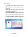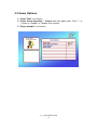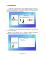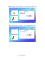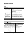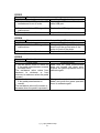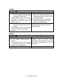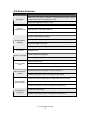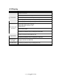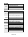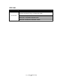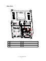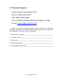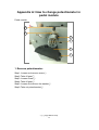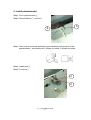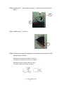
1
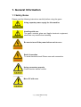
Need parts or service, please contact us:
Injoy Motion Corp.
Technical support: +886-2-2267-6317
Fax: +886-2-2267-5906
E-mail: [email protected]
Note:
• The product specifications are subject to change without notice.
• This game content, equipment and design protected by law, including
patents, copyrights and intellectual property rights.
• Unauthorized reproduction of this document or any of its contents is strictly
prohibited.
©2012 Injoy Motion Corp.
1
©2012 Injoy Motion Corp.
2
©2012 Injoy Motion Corp.
3
©2012 Injoy Motion Corp.
4
Index
1. General Information..........................................6
1.1 Safety Notes.................................................................................................6
1.2 Specifications..............................................................................................7
2. Installation .........................................................8
2.1 Checklist .......................................................................................................8
2.2 Installation....................................................................................................9
3. Game setting (Operator menu) ......................14
3.1 Coin Options..............................................................................................15
3.2 Game Options............................................................................................16
3.3 Pedal Setting..............................................................................................17
3.4 Volume setting...........................................................................................19
3.5 Device Test.................................................................................................19
3.6 Save & Exit .................................................................................................21
3.7 Free Key ......................................................................................................21
3.8 System Recovery......................................................................................22
4. Trouble shooting.............................................23
4.1 Error code...................................................................................................23
4.2 General issues ..........................................................................................26
4.3 Display.........................................................................................................27
4.4 Sound ..........................................................................................................28
4.5 Control.........................................................................................................28
4.6 Link...............................................................................................................29
4.7 Technical Support ....................................................................................31
Appendix A: How to change potentiometer in
pedal module................................32
Appendix B: How to connect tubes...................35
Appendix C: How to change airbag...................37
Appendix D: Clean the drain valve ....................44
Appendix E: Connection for coin accepter ......48
©2012 Injoy Motion Corp.
5
1. General Information
1.1 Safety Notes
Please read the following instructions carefully before using the game.
Using separate power supply for this machine
Handling with care
The game contains glass and fragile electronic equipment,
should be very careful when handling
Be sure to turn off the power before maintenance
Earth Connection
To avoid electrical shock! Please use earth connection.
Using connectors properly
Check direction before connect
Move PC with care
©2012 Injoy Motion Corp.
6
1.2 Specifications
Size
218 x 112 x 235 cm
Weight
350 kg
USA : AC 100-120V, 50/60Hz, 1320W
Europe : AC 220V, 50Hz, 1320W
Rate Power
Occupant weight limit
150 kg
©2012 Injoy Motion Corp.
7
2. Installation
2.1 Checklist
Number
1
○
2
○
3
○
4
○
5
○
Item (For 1 machine)
TV cabinet
Cockpit
Light set
Service manual
Parts kit (screws, keys)
Quantity
1
1
1
1
1
Note: This Machine must be installed indoor, need to maintain a distance of 50
cm with the wall. Make sure the unit stands are placed flat on the ground and the
machine is not moving when playing.
Assembly Diagram
©2012 Injoy Motion Corp.
8
2.2 Installation
Step1 :Take out tubes and connectors.
Note:
A.
1. Remove 2 screws○
C until horizontal position○
B .
2. Open the case○
E ,Take out tubes○
D and all connectors○
F .
3. Open case cover○
©2012 Injoy Motion Corp.
9
Step2:Connecting the tubes
Move cockpit close to TV cabinet, and connect the tubes 56789
from TV cabinet to cockpit 56789 according to the same color.
5
Black Tube
○
6
○ Orange Tube
7
Blue Tube
○
8
○
9
○
No-color Tube
Transparent-Blue Tube
©2012 Injoy Motion Corp.
10
16 ○
17 ○
18 ○
19 ○
20 ○
21 ○
22 ○
23 with
Step3 : Connecting the TV cabinet connectors ○
16 ○
17 ○
18 ○
19 ○
20 ○
21 ○
22 ○
23 by the same pin-number and
cockpit connectors○
the same name tag.
Number
Shape
Pin
Tag name
16
○
4
Motor
17
○
6
Coin Power
18
○
6
Tail light module
19
○
8
Coin cable
20
○
8
Free OP
21
○
12
Bottom cable
22
○
14
AI0-3
23
○
16
Belt & Gear
©2012 Injoy Motion Corp.
11
11 to combine TV cabinet and cockpit together. Sort out all
Step4:Use screws○
wires and then cover the cover4. Use screws to fix it.
4
Cover
○
Phillips screws
10
○
11
○
M5*10L
SHCS M8*25L with
double washer
12 and open back cover○
13 . Put the light set on the TV
Step5:Check Light set○
cabinet and aligned it to the 4 bottom holes inside, then use Phillips
screws to fix it.
Light set
12
○
Cover
13
○
Phillips screws
14
○
M6*12L
Phillips screws
15
○
M5*16L
14 to fix
Step6:Connect the power cable inside the light set and use Screw○
13 .
the cover○
Step7:Connect machine power (220V/8A, 110V/15A)
1. When using power extension cord, the current
capacity should be double.
2. Every power loop only support 2 machine at max.
©2012 Injoy Motion Corp.
12
Coin Acceptor Setting
Step8:Pull up the slider of the coin acceptor and insert the coin into the coin
acceptor. Release the slider to fix the coin acceptor.
Step9:Check the Coin Acceptor Setting. (Select “NO” on top switch, “SLOW”
on bottom switch)
Placement for external plate
Step10:Put a plate on the floor and right under the drain valve.
p l a te
Drain valve
plate
Note: The air compressor tank drains water after machine power off. So it is
necessary to put a container on the floor and right under the drain
valve to catch the water. Generally, a plastic plate around
25x20x3(LxWxH)cm is suggested.
©2012 Injoy Motion Corp.
13
3. Game setting (Operator menu)
To access Operator Menu, after the Power is switched ON and the screen
shows “insert coin”, find the red Operator menu switch located inside the coin
box, switch it to “I” position to enter.
Recovery
Operator Free
Menu
Then you will see below screen.
©2012 Injoy Motion Corp.
14
3.1 Coin Options
1. “Coins per Play” allows you to set how many coins it will take for a
player to start a game. The factory default setting value is 4 coins per
play.
2. “Coins per Continue” allows you to charge a different price for
continue-play from the first game play. The factory default setting value is
4 coins per play.
3. “Currency Type” is not to select the currency of a country, but allows
selection of the forms of currency
4. “Coins per Pulse (Coin Acceptor 1)” allows you to adapt different
currency acceptors. The default value is 1.
5. “Coins per Pulse (Coin Acceptor 2) (Figure 4-4)” allows you to adapt
different currency acceptors. The default value is 1.
6. “Winner Continue” allows you to set up “insert coin to continue or free
to continue” if Winner wants to continue game. This setup is for the
single player mode.
7. “Winner Continue (Net)” allows you to set up “insert coin to continue or
free to continue” if Winner wants to continue game. This setup is for the
multi-player mode.
©2012 Injoy Motion Corp.
15
3.2 Game Options
1. “Game Time” no function.
2. “Game Show Operation” - Enable sets free game play. Click “+” or
“-“ button to “Enable” or “Disable” this function.
3. “Player Number” no function.
©2012 Injoy Motion Corp.
16
3.3 Pedal Setting
Replacing the accelerator or the brake pedal potentiometer may refer to
screen values to install. If the potentiometer values set exceed the safe range
or dead zone after installation, the screen will show the error. Please re-set the
potentiometer values within the safe range.
To calibrate the Pedal and Brake, follow the directions on the screen and
go through these steps.
Step1:Hold the “Calibrate” button on the Panel to calibrate the pedal and
brake. Release the Brake and Pedal, then press “Next” button.
©2012 Injoy Motion Corp.
17
Step2:Press the Brake and Pedal to limit and then press “Next” button.
Step3:After finishing the calibration, press the “Exit” button to exit.
©2012 Injoy Motion Corp.
18
3.4 Volume setting
“Game Volume” can adjust the system volume, suggestion 75~85.
“Idle Movie Volume” can adjust Idle Movie volume, suggestion 15~35.
3.5 Device Test
When into device test, 5 airbags will be aerated,and we can check the
their conditions.
Normal (Full)
Broken (Soft)
©2012 Injoy Motion Corp.
19
Check if all device work properly as well.
©2012 Injoy Motion Corp.
20
3.6 Save & Exit
After the setup is completed, please select “Save & Exit”, and then select
“Yes”. Lastly, switch red Operator menu switch to “O” position and turn OFF the
machine. Then wait for 30secs and turn ON machine power.
3.7 Free Key
Open coin box, press”Free Key” button allows you to play game for free
once.
Free Key
©2012 Injoy Motion Corp.
21
3.8 System Recovery
Recovery switch
OFF
ON
Step1:When the screen shows “insert coin”, Use the key specified for
recovery switch and turn it right.
Step2:Turn the machine off, wait for 30 seconds
Step3:Turn on the power, and you will see screen as below. When
recovery is in progress, do not turn off the power, or the system will be
destroyed permanently.
Step4:If success, will see screen as below.
Step5:Turn the key left and take it out.
Step6:Turn the machine off, wait for 30 seconds
Step7:Turn on the power. <Finish>
©2012 Injoy Motion Corp.
22
4. Trouble shooting
4.1 Error code
EC001
Description The steering wheel fails in automatic calibration.
(The steering wheel does not rotate.)
Check steps
Troubleshooting
1. Check out if the belt is
1. If the belt is come off, please check out the
broken or come off.
reason.
2. If the belt is broken or wear out, please
replace it with the new one with the same
specifications.
2. Check out if the 24V
1. Check out if the cockpit card connector is off.
power supplier is out of
2. Replace the 24V power supplier.
work.
3. Check out if the 24V
1. If there is a 24VDC power connected to the
power is connected to
cockpit card but there is no output to the
the cockpit card.
motor, please replace the cockpit card.
4. Check out if the cockpit
2. If a voltage is transmitted to the motor and the
card has output when
motor does not rotate, please change the
the machine is booting
motor.
up.
5. The cockpit card is out of Replace the cockpit card
order.
EC002
Description
The automatic calibration of the steering wheel is done, but the
value is wrong.
Check steps
Troubleshooting
1. Check out if the potentiometer pins of the If the changes in the
steering wheel are connected inversely.
potentiometer resistance are
(Measure the potentiometer resistance reversed, please swap foot 1
values on feet 2 and 3 with an electric meter. and foot 3.
The potentiometer resistance increases as If there is no change in the
the steering wheel moves clockwise, and potentiometer resistance,
decreases as the steering wheel moves please replace the
counterclockwise. )
potentiometer.
2. The cockpit card breaks down.
Replace the cockpit card.
©2012 Injoy Motion Corp.
23
EC003
Description The cockpit card can not be recognized.
Check steps
Troubleshooting
1. Check out if the USB port of the IPC Replace the USB connector to the
motherboard is out of order.
other USB port.
2. Check out if the USB signal line Replace the USB signal line.
malfunctions.
3. The cockpit card malfunctions.
Replace the cockpit card.
EC004
Description The communication of the Cockpit Card USB is disrupted.
Check steps
Troubleshooting
1. Check out if the USB signal line Change the USB signal line and
malfunctions.
check out if the ground wire of the
motor is fixed on the plate.
2. The cockpit card malfunctions.
Replace the cockpit card.
EC005
Description Pedal calibration error
Check steps
1. Use an electric meter to check out
if the pedal potentiometer exceeds
the dead zone.
(The resistance value varies from
maximum to minimum or from
minimum to maximum when the pedal
is press.)
2. Use an electric meter to check out
if the pedal potentiometer is
normal.
(The resistance value will increase or
decrease when the pedal is pressed.)
Troubleshooting
Make sure the pedal potentiometer
does not exceed the dead zone,
re-enter the game operation menu to
calibrate again.
Change the potentiometer of the
pedal, and enter the game operation
menu to calibrate again.
©2012 Injoy Motion Corp.
24
EC006
Description Brake calibration error
Check steps
1. Use an electric meter to check
out if the brake potentiometer
exceeds the dead zone.
(The resistance value varies from
maximum to minimum or from
minimum to maximum when the
pedal is press.)
2. Use an electric meter to check
out if the brake potentiometer is
normal.
(The resistance value will increase
or decrease when the pedal is
press.)
Troubleshooting
1. Make sure the brake potentiometer
does not exceed the dead zone,
re-enter the game operation menu
to calibrate again.
2. Change the brake potentiometer,
and enter the game operation
menu to calibrate again.
Change the brake potentiometer, and
enter the game operation menu to
calibrate again.
EC007
Description Automatic calibration of the steering wheel fails.
Check steps
Troubleshooting
1. Use an electric meter to check out Replace the wheel potentiometer.
if the wheel potentiometer is (Please
note
if
the
wheel
normal.
potentiometer exceed the dead zone
(The resistance value will increase the wheel potentiometer is to be
or decrease when the steering replaced.)
wheel turns left and right.)
2. The cockpit card malfunctions.
Replace the cockpit card.
©2012 Injoy Motion Corp.
25
4.2 General issues
Problem
Solution
No power
Make sure the power connector is connected and have correct
voltage. Make sure all switches are “ON”.
Check the distribution switch is “ON”.
Reconnect the token and restart.
PC can’t
recognize token
Change token to another USB port.
Contact Injoy Motion Corp. to change token.
Using a separate power supply
PC shut down
suddenly
Make sure the computer power cord and switch work properly.
Reconnect RAM, VGA card
Change the PC power supply.
PC Crash
Restart the PC.
Check all fans work properly.
Machine overheat
Ensure no objects block the vents.
Remove stuck coins.
Can not insert
coin
Go to operator menu check coin setting.
Reinstall reference coin.
Can not recover
system
Make sure recover USB disk is connect to the PC.
Contact Injoy Motion Corp. to change the Hard Disk.
Check wire connecting between cockpit card and OP switch.
Can not enter
operator menu
Recover the system
Contact Injoy Motion Corp. to change the cockpit card.
Free Key not
functional
Check wire connecting.
Contact Injoy Motion Corp. to change the cockpit card.
©2012 Injoy Motion Corp.
26
4.3 Display
Problem
Solution
Update VGA driver.
Check screen wire connecting.
No screen
Check VGA card wire connecting.
Contact Injoy Motion Corp. to change the VGA card.
Contact Injoy Motion Corp. to change the LCD.
No screen and
no sound
Ensure PC power input is correct.
Ensure PC power switch is “ON”
Restart the PC.
Recover the system
Contact Injoy Motion Corp. to change the Hard disk.
Update VGA driver and restart the PC.
Lag problem
Contact Injoy Motion Corp. to change the VGA card.
Resolution is
not right
LCD abnormal
Change resolution to1280x768.
Contact Injoy Motion Corp. to change the LCD.
©2012 Injoy Motion Corp.
27
4.4 Sound
Problem
Solution
Go to operator menu change volume setting.
Adjust amplifier volume.
No sound
Check wire connecting.
Contact Injoy Motion Corp. to change the amplifier.
Poor sound
Contact Injoy Motion Corp. to change the amplifier.
4.5 Control
Problem
Solution
Change micro switch.
START / VIEW
Button failure
Check wire connecting.
Contact Injoy Motion Corp. to change the cockpit card.
Check motor wire connecting.
Contact Injoy Motion Corp. to change the motor.
Wheel failure
Change the potentiometer.
Contact Injoy Motion Corp. to change the cockpit card.
Check wire connecting and micro switches.
Gear not working
Contact Injoy Motion Corp. to change the cockpit card.
Go to operator menu check pedal setting and do calibration.
Pedal and brake
not working
Change the potentiometer.
Contact Injoy Motion Corp. to change the cockpit card.
Go to operator menu device test and check if all airbags work fine.
Make sure the power switch of the air compressor is ON.
Airbag not
working in the
game.
Check if air compressor works properly.
Check the 12V on the SSR card near the cockpit card.
Contact Injoy Motion Corp. to change air compressor or SSR card.
©2012 Injoy Motion Corp.
28
4.6 Link
Problem
Solution
Make sure cable is good.
Contact Injoy Motion Corp. to Change the cable.
Can not link
Make sure no duplicate IP address.
Make sure no duplicate computer name.
Make sure all software is the same version.
©2012 Injoy Motion Corp.
29
Main Parts
1
○
2
○
3
○
4
○
PC
Air compressor
Cockpit card
Power supply
5
○
6
○
7
○
8
○
Extension card
Transformer (only for 220V machine)
Pneumatic valve
Input AC power
©2012 Injoy Motion Corp.
30
4.7 Technical Support
Service center: Injoy Motion Corp.
Phone: +886-2-2267-6317
Fax: +886-2-2267-5906
Time: 9:00AM~6:00PM (GMT+8), Monday to Friday
E-mail: [email protected]
When you contact technical support, please provide the following
information so that we can understand the situation and solve your problem as
soon as possible, thank you for your cooperation:
1、Machine serial number ___________________________________
2、Software version _______________________________________
3、Error code ___________________________________________
4、Problem Description _____________________________________
5、Any changes to the system ________________________________
©2012 Injoy Motion Corp.
31
Appendix A: How to change potentiometer in
pedal module
Pedal module:
6
5
3
4
2
1
1. Remove potentiometer:
◎
1 .
Step1: Loosen and remove screw○
2 .
Step2: Take off gear○
3 .
Step3: Loosen screw○
4 .
Step4: Take off gear○
5 .
Step5: Loosen and remove the washer○
6 .
Step6: Take out potentiometer○
©2012 Injoy Motion Corp.
32
2. Install potentiometer:
◎
6 .
Step1: Put in potentiometer○
5 and fix it.
Step2: Placed Washer○
5
6
Step3: Use meter to measure resistance value between pin2 and pin3 of the
potentiometer,and make sure 1.6Kohm for pedal, 2.6Kohm for brake.
4 .
Step4: Install gear○
3 .
Step5: Fix screw○
3
4
©2012 Injoy Motion Corp.
33
2 ,and make sure gear○
4 close to second tooth of the
Step6: Install gear○
2 .
gear○
4
2
1 and fix it.
Step7: Install screw○
1
Step8: Use meter to measure resistance value between pin2 and pin3 of the
potentiometer. <Finish>
Release accelerator should be 1.6 Kohm
Press the accelerator should be 3.2 Kohm
Release the brake should be 2.6 Kohm
Press the brake should be 3.5 Kohm
©2012 Injoy Motion Corp.
34
Appendix B: How to connect tubes
1. Insert
A. Insert the tube to the end.
B. Finish
©2012 Injoy Motion Corp.
35
2. Pull out
A. Push the releasing ring in the front of the quick coupler.
B. Pull out the tubes
©2012 Injoy Motion Corp.
36
Appendix C: How to change airbag
A. Introduction
B. Change Airbag no.1~4
C. Change Airbag no.5
A. Introduction
Front:Airbag no.1
Right: Airbag no.4
Mid: Airbag no.5
Back: Airbag no.2
Left: Airbag no.3
1 Airbag screws
○
2 Fixation screws
○
3 Airbag screws
○
4 Quick coupler
○
©2012 Injoy Motion Corp.
37
B. Change Airbag no.1~4(Take changing airbag no. 3 for example)
)
Step1:Use solid object to support the motion base.
Step2:Remove 2 airbag screws.
Step3:Remove 4 fixation screws.
©2012 Injoy Motion Corp.
38
Step4:Remove the tube(refer to Appendix B).
Step5:Remove 2 airbag screws and quick coupler.
Step6:All Components are as below.
©2012 Injoy Motion Corp.
39
Step7:After change airbag, tighten 2 airbag screws and quick coupler.
Step8:Install 4 fixation screws.
Step9:Install 2 airbag screws. <Finish>
©2012 Injoy Motion Corp.
40
C. Change Airbag no.5
Step1:Remove 4 seat fixation screws.
(Left)
(Right)
Step2:Remove the seat.
Step3:Remove 2 airbag screws.
©2012 Injoy Motion Corp.
41
Step4:Open the seat base, and find the airbag 5.
333
Step5:Remove 2 fixation screws.
Step6:Remove the tube and screws, and change airbag.
©2012 Injoy Motion Corp.
42
Step7:After changing, lock 2 airbag screws, tube, and 2 fixation screws.
Step8:Cover the seat base, tighten 2 airbag screws.
Step9:Install the seat back. <Finish>
©2012 Injoy Motion Corp.
43
Appendix D: Clean the drain valve
Drain valve
Follow the steps below to clean the pathway inside the drain valve:
1. Remove the metal piece
©2012 Injoy Motion Corp.
44
2. Remove the body-part
3. Remove 4 screws
4. Remove the core-part
©2012 Injoy Motion Corp.
45
5. Clean the two-way valve inside
6. Install the core-part
7. Install 4 screws
©2012 Injoy Motion Corp.
46
8. Install the body-part
9. Install the metal piece <Finish>
©2012 Injoy Motion Corp.
47
Appendix E: Connection for coin accepter
LINE-AP-COIN is the main cable for the coin accepter. There are three
branches for LINE-AP-COIN:
1. “Coin-P” input power 12V to the coin accepter.
Connector assignment:
Pin1: 12VDC
Pin2: ground
Pin3: none
Pin4: none
2. “Coin-Ex” output credit signal from the coin accepter
Connector assignment:
Pin1: credit pulse
Pin2: ground
3.
“Count” output coin count to the counter
Connector assignment:
Pin1: coin count
Pin2: 12VDC
©2012 Injoy Motion Corp.
48