1
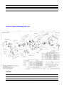
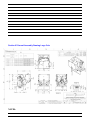
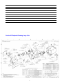
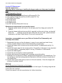
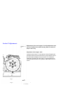
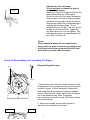
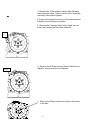
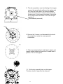
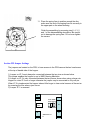
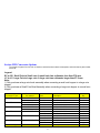
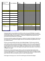
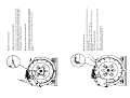
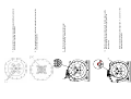
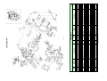
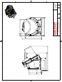
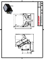
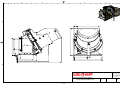
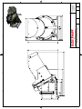
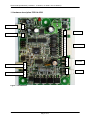
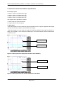
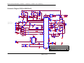
SERVICE MANUAL
FOR
BB2
TM
Rev. 01
Date: 091108
Service manual
Table of Contents
Section I
Introduction .
. . . . . . . . . . . . . . .
Section II
New Features .
. . . . . . . . . . . . . .
. . . . Page 2
. . . . . Page 2
Section III
Hopper Configurations . . . . . . . . . . . . . . . . Page 3
Section IV
General Assembly Drawing Small Coin . . . . . . . . .
Page 4
Section V
Exploded View Small Coin . . . . . . . . . . . . . . Page 5
Section VI
General Assembly Drawing Large Coin. . . . . . . . .
Section VII
Exploded View Large Coin. . . .
Section VIII
Specifications . . . . . . .
.
Page 6
. . . . . . . . . . .
.
.
.
.
.
.
.
.
Page 7
. Page 8
Section IX
Maintenance . . . . . . . . . .
. . . . . . . . . .
Page 8
Section X
Adjustments . . . . . . . . . .
. . . . . . . . . .
Page 10
Section XI
Assembly and Disassembly of Hopper. . . . . . . . . . Page 11
Section XII
Jumpers . . . . . . . . . . .
. . . . . . . . . .
Page 14
Section XIII
Conversions . . . . . . . . . .
. . . . . . . . . .
Page 15
Section XIV
Theory of Operation . . . . . . .
. . . . . . . . . .
1
Page 16
Section I Introduction
Nearly 30 years of designing and manufacturing Casino Hoppers has resulted in this
new product.
Suzo ® a world leader in coin handling equipment and well know for its Cube Hopper ® and
Gold Series hopper ® now presents the Excel Hopper ®. Understanding the needs of both
casinos and slot machine manufacturers has led to this extremely durable and World’s most
service friendly Casino hopper!
Section II New Features
New features:
Planetary gearbox system provides the following advantages:
Maximum torque with minimal power consumption.
Standard 24VDC
Silent Operation.
Unique bayonet connection for easy and economical motor replacement.
Standard optical read out sensing coin presences :
The first sensor is operated by the coin pushing a mechanical lever to interrupt an
optical sensor.
The output method available for your control board is:
Standard: Indirect optical read out. Part Number 14-1145
The second sensor is standard for WMS Gaming and works by the coin breaking a
beam of infrared light.
This sensor adds an additional security level to prevent coin stealing.
Second read out located in the coin exit.
Optics protected by cover against light (fraud) and dust.
Other features:
Easy accessible coin exit.
Steel bearing offer stable disc rotation.
Customized frame and cup specifications.
All wear and tear parts such as pin and shelf wheel are 100% compatible with older
generations STC hoppers.
Software displays version on power up by blinking Green Led for units and Red Led for
tenths. Software version also displayed on label next to PCB.
Snap type transparent plastic cover provides protection against liquid spills.
Tilt Bracket designed for use when filling coins to prevent hopper from tipping over yet Tilt
Bracket can easily be moved out of way when sliding hopper into cabinet.
Easy access to adjust thickness setting for coin wiper to allow only one coin on knife.
Large coin hoppers have clutch to help reduce coin jams.
Large coin hopper has jumper selection to help provide second try in clearing coin jams.
2
Applicable coin size Diameter: 19-38mm.
Applicable coin size Thickness: 1.5-3.8mm.
Approximate Pay out speed:
<31mm coins: Up to 450 coins per minute
>31mm coins: Up to 250 coins per minute
Control boards: (optional)
Part no. 14-0530-5 intelligent control board 12 or 24Vdc with logic Lo start mode.
.
For field replacements contact factory.
Section III HOPPER CONFIGURATIONS
Complete
Hopper
WMS Part No.
A-022379-00-02
A-022379-00-03
A-022379-00-04
A-022379-00-05
A-022379-00-06
A-022379-00-07
A-022379-00-08
A-022379-00-09
A-022379-00-10
A-022379-00-11
A-022379-00-12
A-022379-00-13
Suzo Happ No.
16-WMS00202SL
16-WMS00203SL
16-WMS00204SL
16-WMS00205SL
16-WMS00206SL
16-WMS00207SL
16-WMS00214SL
16-WMS00215SL
16-WMS00216SL
16-WMS00217SL
16-WMS00218SL
16-WMS00219SL
Min.
Dia.
Coin
(mm)
Max
Dia
Coin
(mm)
19
Shelf Wheel
Pin
Wheel
Knife
Outlet
Cover
20
14-0130-1465
14-0116
14-0281
14-0065
845
20.1
21.2
14-0130-1465
14-0116
14-0281
14-0065
845
21.3
22
14-0130-1425
14-0116
14-0281
14-0065
845
22.1
24.8
14-0130-1370
14-0115
14-0281
14-0065
845
24.9
25.8
14-0130-1350
14-0115
14-0281
14-0065
845
25.9
27.8
14-0130-1310
14-0115
14-0281
14-0065
845
27.9
31
14-0130-1235
14-0115
14-0296
14-0067
855
x
31.1
31.9
14-0130-1235
14-0112
14-0296
14-0067
855
x
32
33
14-0130-1205
14-0112
14-0296
14-0067
855
x
33.1
35
14-0130-1165
14-0112
14-0296
14-0067
855
x
35.1
36.9
14-0130-1125
14-0112
14-0296
14-0067
855
x
37
38
14-0130-1075
14-0112
14-0296
14-0067
855
x
NOTES:
3
Bowl
Stir
Section IV General Assembly Drawing Small Coin
NOTES:
4
Section V Exploded Drawing Small Coin
NOTES:
5
Section VI General Assembly Drawing Large Coin
NOTES:
6
Section VII Exploded Drawing Large Coin
7
NOTES:
Section VIII Specifications
Power Consumption:
Voltage
Unloaded
24VDC
0.25 Amp
Loaded
0.50 Amp
Stall auto reverse
1.5 Amp
Maximum torque of the motor
24V - 21RPM load 12kg N-m
Environmental Specifications:
Operating temperature: 0° to + 60°C
Storage temperature: -10° to + 65°C
Mechanical Dimensions:
Front (looking at Blind Mate Connector pin side) 12.14 “ x side 9.63” x height11.82”.
Refer to General Assembly drawing in front of manual.
Weight: 16.9 lbs.
Electrical Connections:
1. Connector: 25 Pin Blind Mate
2. Pin 1 Hopper Full: Diode protected. Active state: Ground. Supplied by Hopper.
3. Pin 4 Hopper On: CMOS TTL Levels: Low 0-0.8VDC, high 2.0-5.2 VDC. Active state (Motor On): Low. opto
coupled Input.
4. Pin 7 Hopper Coin Count: Open collector output to ground opto coupled. Active State: Ground. Supplied by
Hopper. Valid coin count is 26ms pulse, Jam > 250ms.
5. Pin 12 Power: 24 VDC.
6. Pin 21 Frame Ground
7. Pin 23 Ground
8. Pin 25 Ground
8
Note: Pin 23 and 25 are tied together.
Section IX Maintenance
Periodic maintenance
(Warning: Before removing or installing the hopper make sure that power is switched
off!)
Tools Required for Service:
12 Inch long Shaft Phillips Screw Driver for M5 screws PH1 Tip
4 Inch long Shaft Phillips Screw Drive for M5 screws PH1 Tip
7 Inch Needle Nose Pliers
8 mm socket driver
7 mm socket driver
4 mm Allan wrench
5 mm Flat Tip Screw Driver with 4 mm tip
Maintenance recommended in six months interval.
1. Clean the optical sensor with can air. Use air spray can Suzo Happ part number 291900-00.
2. Clean the hopper knife and remove all dirt, especially on the route of coins, on the shelf
wheel, the
pinwheel around the area of the pins, the coin outlet, plastic bowl and
metal parts in the bowl. Refer Section XI on how to remove bowl.
Inspection, recommended once a year. Refer to Section XI for Disassembly and
Assembly Instructions.
1. Disassemble the coin cup from the hopper, in case of a non-metal cup check for any
cracks or breaks. Refer to section XI for disassembly and assembly.
2. Inspect the hopper knife for wear and the correct position! For adjustments see fig.1 in
section X.
3. Inspect the hopper wiper for the correct position. The position of the wiper is very important
for a correct payout! If necessary adjust it, see fig. 2 of section X of this manual.
4. Inspect the rubber agitator.
5. Inspect the coin level probe is securely fastened.
6. Inspect cable harness for damage and if necessary secure the cables.
7. Assemble coin cup with the 4 screws, springs and bushings back on the wheelhouse. The
two springs go over the bushings and are inserted into the hole at the top of each side of
the hopper bowl.
8. Inspect if the hopper slides gently in and out of the slot machine. Check the hopper and
connector for proper function.
Warning!
Do not use any kind of lubrication on the hopper.
After inspection and maintenance check the function of the hopper. For testing using the test
mode of the slot- machine.
Consult the manual or the slot-manufacturer for further instructions.
9
Section X Adjustments
Adjustments of the excel hopper. For knife adjustment must
remove Coin Bowl from wheel housing. Refer to section XI
steps 1 and 2 only.
Adjustment of the hopper knife
Loosen the two screws “A” move the tip of the knife against the
pinwheel and the top of the shelf wheel. Lightly hold the knife on
the shelf wheel and tighten the two screws “A” 5.5 Newton’s.
Rotate the pinwheel and check there is no space between the
shelf wheel and the knife in any position. Note Outlet cover not
shown.
A
Fig: 1
Fig: 2
10
Adjustment of the coin-wiper
You do not have to remove the bowl to
make this adjustment
Referring to Figure 2A slightly loosen the two
Allan screws at the top of the hopper.
Position a coin in the coin wiper comparator.
Keep the back of the wiper edge up against
the wheel housing while moving the front of
the wiper up against the coin sandwiching it
between the two wiper plates. Do not
sandwich the coin too tight. The coin should
be able to roll back and forth. Tighten the
two Allan screws. Do not over tighten. This
will adjust the wiper to be approximately 0,5
mm (.019”) from the coin.
Fig. 2A
Check:
When adjusted properly the coin should move
freely under the wiper. A second coin laying on top
of the first coin should get wiped off the first coin
when both try to pass under the wiper.
Section XI Disassembling And Assembling The Hopper.
Disassembling the hopper.
Step 1
Step 2
1. Remove the yellow wire from probe terminal on side
of hopper and remove purple wire from ground terminal
on side of hopper. (Ground terminal is connected to
back metal plate and is closes to horseshoe shaped
sensor). Remove the 4 screws, which holds the hopper
cup to the wheel housing. Note: The springs
surrounding the screws are on top. The bottom screws
only have bushings.
2. Remove the hopper cup and spring which is
mounted on the right side of pivot pin.
Step 4
Step 3
11
3. Remove the 2 Allan screws, which holds the wiper,
and remove the wiper. Refer to section XI for assembly
and setup. Store parts together.
4. Remove the screw from the top of the second sensor.
Carefully remove the second sensor.
5. Remove the 2 hexagon bolts, which holds the coin
chute, and remove the coin chute and knife.
Step
5
Step 6
6. Remove the 2 Philips screws, which holds the coin
deflector, and remove the coin deflector.
7. Remove the Philips screw, and spring in the centre
of the disc.
12
8. The disc assembly is now free floating in the hopper,
remove the assembly by pulling on the agitator and
lift it from the motor shaft. If a clutch is installed
(coins >27.9 mm) then it must be removed first by
loosening the 3 set screws at the base of the clutch.
Do not remove the set screws. The clutch will pull
straight off.
( Disc assembly removed)
Step 8
8. Remove the 3 screws, and disassemble the whole
disc assembly to make the new requested
combination.
9
9. Take requested pinwheel, shelf-wheel, agitator and
agitator support plate and mount the 3 screws back in
position. Do not over tighten.
10
10. Put the disc assembly back on the hopper.
The disc only fits 2 ways into the driver pin.
13
11. Place the spring liner in position around the disc,
make sure the end of the spring liner fits correctly in
the upper part on the wheel housing.
Finish the assembling by reversing step 5, 4, 3, 2
and 1 of the disassembling description. Be careful
not to damage the spring liner. Do not over tighten
the screws.
11
Section XII Jumper Settings
The jumpers are located on the PCB, to have access to the PCB remove the hex head screw
at the top of handle side of the hopper.
1) Jumper on JP 3 must always be connected between the two pins as shown below.
This jumper enables the hopper to run in WMS Gaming Machines.
2) Jumper on JP 2 is only connected between the two pins as shown when using a large coin
hopper for coins 27.9 mm or larger otherwise the jumper may be connected to only one pin.
When JP 2 is implemented the hopper takes a little longer to clear coins because of there size
by reversing the disc when a jam occurs.
3) Jumper JP 1 is reserved.
J4
J8
J3
$1 tkn WMS
Select. Select.
Serial
Port
J5
JP1 JP2 JP3
J2
J6
S/W Version 2.3
J1
14
J7
Section XIII Conversion Options
To convert a hopper from one coin to another, select the size under the description and order the kit part number
to the left.
Legend:
SC to SC: Small Coin to Small coin. A small coin has a diameter less than27.9 mm.
LC to LC: Large Coin to Large coin. A large coin has a diameter larger than 27.8 mm.
Note:
1) Only purchase a large coin bowl assembly when converting a small coin hopper to a large coin
hopper.
2) Only purchase a Small Coin Bowl Assembly when converting a large coin hopper to a small coin
hopper.
Conversion Type
SC to SC
Kit Part Number to
be ordered
14-1175-WMS-A2
SC to SC
14-1175-WMS-A3
SC to SC
14-1175-WMS-A4
SC to SC
14-1175-WMS-A5
SC to SC
14-1175-WMS-A6
SC to SC
14-1175-WMS-A7
Conversion Type
Kit Part Number
BOM
14-0130-1465
14-0116
14-0130-1465
14-0116
14-0130-1425
14-0116
14-0130-1370
14-0115
14-0130-1350
14-0115
14-0130-1310
14-0115
BOM
15
Description
19.0-20.0 Shelf Wheel
Pin Wheel
20.1-21.2 Shelf Wheel
Pin Wheel
21.3-22.0 Shelf Wheel
Pin Wheel
22.1-24.8 Shelf Wheel
Pin Wheel
24.9-25.8 Shelf Wheel
Pin Wheel
25.9-27.8 Shelf Wheel
Pin Wheel
Description
Qty
1
1
1
1
1
1
1
1
1
1
1
1
QTY
Large Coin Bowl
Assembly
SC to LC Bowl Assy
Conversion Type
LC to LC
14-1175-WMS-A8
Kit Part Number
14-1175-WMS-A14
LC to LC
14-1175-WMS-A15
LC to LC
14-1175WMS-A16
LC to LC
14-1175-WMS-A17
LC to LC
14-1175-WMS-A18
LC to LC
14-1175-WMS-A19
Conversion Type
Small Coin Bowl
Assembly
LC to SC Bowl Assy
Kit Part Number
14-1175-WMS-A20
14-0296
14-0067
14-0585
14-0581
14-0580-1
150-025-522
16-HOCU-855
BOM
14-0130-1235
14-0115
14-0130-1235
14-0112
14-0130-1205
14-0112
14-0130-1165
14-0112
14-0130-1125
14-0112
14-0130-1075
14-0112
BOM
Knife
Outlet Cover
Clutch
Agitator Deflector
Metal Support Agitator
M5x25 Scw PH FH HD
Large Hopper Cup Assembly
Description
27.9-31.0 Shelf Wheel
Pin Wheel
31.1-31.9 Shelf Wheel
Pin Wheel
32.0-33.0 Shelf Wheel
Pin Wheel
33.1-35.0 Shelf Wheel
Pin Wheel
35.1-36.9 Shelf Wheel
Pin Wheel
37.0-38.0 Shelf Wheel
Pin Wheel
Description
1
1
1
1
1
3
1
Qty
1
1
1
1
1
1
1
1
1
1
1
1
Qty
14-0580
150-025-522
16-HOCU-845
14-0065
14-0281
Metal Star Support Agitator
M5X20 Scw Button HD
Small Hopper Cup Assembly
Outlet Cover
Knife
1
3
1
1
1
Section XIV Theory of Operation
Upon power up if you were looking at the PCB you will see the green LED blink twice and the
red LED blink 3 times. This is the version of software being implemented at the time this manual
was being printed and is version number 2.3. This must correspond with the label next to the
PCB located on the PCB Bracket of the hopper.
The game controls the running of the hopper by sending a low signal to the hopper and as long as
the second sensor is not blocked the hopper will start to run until either the game tells it to stop
or a jam has occurred.
There are two sensors that the coins pass when exiting the hopper. The first one provides the
count and the second one make sure that the exit coin path is clear. In the event the coin path at
the second sensor becomes obstructed the hopper will shut down however, if cleared within two
seconds it will restart to continue to pay out the correct number of coins. After two seconds the
hopper will have to receive a new start signal from the game and the jam must be cleared before
sending the start signal.
If a jam occurs in the bowl the hopper will try to clear it by moving the disc backward and
forward for approximately 8 - 12 seconds depending on if you have a small coin hopper or large
coin hoper then stopped if not cleared. The process continues with each new start signal until the
jam is cleared. In some case it maybe necessary to remove the jam manually.
If the hopper does not pay out a coin in 15 seconds the game will shut off the hopper.
16
Suzo Happ Group® does not accept any errors contained in this document. This document is for reference only and subject to change without notice.
WWW.HAPP.COM or WWW.SUZO.COM
This document is the private property of Suzo Happ Group and may not be reproduced in part or in total by means, electronic or otherwise
without the written permission of Suzo Happ.
Suzo Happ Group does not accept any errors contained in this document.
Design and specifications are subject to change without prior notice.
Please make sure you are using the correct configuration for the size of the coins needed for the hopper, combination of pinwheel, shelfwheel, etc.
In case of doubt, do not hesitate to contact
SUZO HAPP GROUP for advice!
Tel: 1 (847) 593 6161 is USA
Tel: +31 186 643333, in Europe The Netherlands
17
Developed by Suzo International
Version 1.3
SERVICE MANUAL
Loaded
0.50 Amp
0.70 Amp
12V - 31RPM load 5kg N-m
12V - 21RPM load 11kg N-m
Stall auto reverse
1.5 Amp
1.6 Amp
1
Operating temperature: -10° to + 60°C
This service manual is intended only to assist the reader in the use of this product.
Therefore Suzo international shall not be held liable for any loss or damage whatsoever arising from the use of any information or
particulars in or any comission from this manual or any incorrect use of the product.
Maximum torque of the motor
• 24V - 31RPM load 6kg N-m
• 24V - 21RPM load 12kg N-m
Power Consumption:
Voltage
Unloaded
• 24VDC
0.25 Amp
• 12VDC
0.30 Amp
Warning!
Do not use any kind of lubrication on the hopper.
After inspection and maintenance check the function of the hopper. For testing using the test mode of the slot- machine.
Consult the manual or the slot-manufacturer for further instructions.
Inspection, recommended once in a year
1. Disassembling the coin cup of the hopper, in case of a non-metal cup check for any cracks or brakes.
2. Inspect the hopper knife for wearing and the correct position! For adjustments see fig.1
3. Inspect the hopper wiper for the correct position.
The position of the wiper is very important for a correct payout! If necessary adjust it, see fig. 2
4. Inspect the rubber agitator.
5. Inspect the coin level, check the moment of the switch or check if the coin level probe is securely fastened.
6. Inspect cabling harness for damage, and if necessary tighten cables back on the harness.
7. Assembling coin cup with the 4 screws, springs and bushings back on the wheelhouse.
8. Inspect if the hopper slides gently in and out of the slot machine. Check the hopper and connector for proper function.
Maintenance recommended in six months interval.
1. Clean the optical sensor.
2. Clean the hopper knife and remove all dirt, especially on the route of coins, on the shelf wheel, the
pinwheel around the area of the pins and the coin outlet.
Periodic maintenance
(Warning: Before removing or installing the hopper make sure that power is switched off!)
Control boards: (optional)
Part no. 14-0500-1 intelligent control board 24Vdc with direct start mode, logic Hi start mode, pulse mode and RS232 serial mode.
Part no. 14-0500-2 intelligent control board 24Vdc with direct start mode, logic Lo start mode, pulse mode and RS232 serial mode.
Part no. 14-0505-1 intelligent control board 12Vdc with direct start mode, logic Hi start mode, pulse mode and RS232 serial mode.
Part no. 14-0505-1 intelligent control board 12Vdc with direct start mode, logic Hi start mode, pulse mode and RS232 serial mode.
Part no. 14-0500-4 anti-jam control board 24Vdc to solve most of the possible coin jams during operation.
<31mm coins: 450 coins per minute
>31mm coins: 250 coins per minute
All Excel hoppers can be supplied with customised wiring, with choice of strobe pins for
low and / or high level detection
Pay out speed:
Other features:
• Easy accessible coin exit.
• Steel bearing offer stable disc rotation.
• Customised frame and cup specifications possible.
• All wear and tear parts such as pin and shelf wheel are 100% compatible with older generations STC hoppers.
• Easy to integrate for manufacturers who use older generation STC casino Hoppers.
• Applicable coin sizes: 18-38mm – Optional up to 45mm.
Standard optical read out:
• Indirect optical read out. NPN, normally open (n/o).
• Optional: Indirect optical read out. NPN, normally closed (n/c).
• Optional: Second read out in the coin exit.
• Optics protected by cover against light (fraud) and dust.
Planetary gearbox system provides following advantages:
• Maximum torque by minimal power consumption.
• Available in 12 or 24VDC
• Silent Operation.
• Unique bayonet connection for easy and economical motor replacement.
New features:
Nearly 25 years of designing and manufacturing Casino Hoppers has resulted in this new product.
Understanding the needs of both casinos and Slot machine manufacturers has led to this extremely durable and World’s
most service friendly Casino hopper!
Service manual
A
Fig: 2
Fig: 1
B
C
2
Tighten first the screw “B”, constantly checking the position of the wiper to the
coin.
Tighten screw “C” and check the final position.
Do not over-tighten the screws B en C!
Position a coin under the wiper, make sure that the top of the wiper is equal to
the top of the coin.
Slightly loosen the two screws “B and C” - see fig 2.
Move the wiper edge up to the coin. The edge should be close to the coin,
app. 0,5 mm.
Never let the wiper touch the coin!
Adjustment of the coin-wiper
Loosen the two screws “A” move the tip of the knife against the pinwheel and
the top of the shelfwheel. Turn the pinwheel at least one cycle and tighten the
two screws “A”. Rotate the pinwheel and shelfwheel and the knife in any
position.
Adjustment of the hopper with full metal knife
Loosen the two screws “A” move the tip of the knife against the pinwheel and
the top of the shelfwheel. Lightly hold the knife on the shelfwheel and tighten
the two screws “A”. Rotate the pinwheel and check there is no space between
the shelfwheel and the knife in any position.
Adjustment of the hopper with standard knife
Adjustments of the excel hopper
5
4
1
5
3
2
3
6. Remove the Philips screw, and spring in the centre of the disc. The disc
assembly is now free floating in the hopper, remove the assembly by pulling on
the agitator and lift it from the motor shaft.
5. Remove the 2 Philips screws, which holds the coin deflector, and
remove the coin deflector.
4. Remove the 2 hexagon bolts, which holds the coin chute, and
remove the coin chute and knife.
3. Remove the 2 hexagon bolts, which holds the wiper, and remove
the wiper.
2 Remove the hopper cup and spring which is mounted on the right
side of pivot pin.
1. Remove the 4 screws, which holds the hopper cup to the
wheelhousing.
Disassembling the hopper.
9
7
10
8
4
Finish the reassembling by reversing step 5, 4, 3, 2 and 1 of the
disassembling description.
end of the spring liner fits correct in the upper part on the
wheelhousing.
10. Place the spring liner in position around the disc, make sure the
9. Put the disc assembly back on the hopper.
The disc only fits 2 ways into the driver pin.
8. Take requested pinwheel, shelf-wheel and agitator, and mount the
3 screws back in position.
7. Remove the 3 hex key screws, and disassemble the whole disc to
make the new requested combination.
14-0400
5040-191
14-0140
SEE PART LIST G
SEE PART LIST H
1050-242
14-0345
14-0085
14-0890-1
14-0470
0052-276
0081-006
61-2257-31
14-0720-6
14-0365
14-0440
1051-040
150-025-220
150-012-120
150-012-420
14-0335
21
PART
NUMBER
1
2
3
4
5
6
7
8
9
10
11
12
13
14
15
16
17
18
19
20
DRAW.
NR.
DESCRIPTION
SPRING LIGHT
PIVOT ROD
E WASHER BLACK (DIN 6799)
SPRING LINER
METAL STAR SUPPORT AGITATOR
CUP LINER
M5 TENSILOCK NUT
EXTENSION SPRING
COIN BAFFLE
MEDIUM SCOOP EXTENSION AINS
LEVELSENSOR PIN
ISOLATION SLEEVE 5.2X7.9X1
ISOLATION WASHER 8.1X14X1
TAB 6.3MM BRASS HOLE 5.3MM 45GR
HOPPER CUP 2 PCS STANDARD BLUE
SPRING HEAVY
MOUNT
M5 EXT. STAR LOCKWASHER YELLOW
M5X25 SCREW PHILL. PAN HD YELLOW
M5X12 SCREW PHILL. PAN HD YELLOW
M5X12 SCREW PHILL.FLAT HD YELLOW
22
23
24
25
26
27
28
29
30
31
32
33
34
35
36
37
38
39
40
41
5
* SEE LIST 14-1175
2
1
2
1
1
1
9
1
1
1
1
1
1
2
1
2
4
4
4
3
2
PCS
Version 1.0
DRAW.
NR.
PART
NUMBER
14-0075
150-010-120
250-008-700-7
14-0025
14-0035
240-010-700-7
14-0960-14
240-008-700-7
14-1022
14-0015
14-0051
14-0009
14-0045
14-0355
14-0500-1
22-0087
22-0068-1
22-0068-3
14-0501-2
14-1175*
16-5038-XX
DESCRIPTION
SCOOP SUPPORT BRACKET
M5X10 SCREW PHILL. PAN HD YELLOW
M5X8 BOLT HX. HD. TAPT. FL. YELLOW
RIGHT SIDE MOUNTING BRACKET
PIVOT BRACKET
M4X10 BOLT HX. HD. TAPT FL. YELLOW
CABLE LOOM AINS
M4X8 BOLT HX. HD. TAPT FL. YELLOW
CONNECTOR BRACKET AMP 12 PINS
LEFT SIDE MTG BRACKET
BOTTOM GRIP
PLATFORM 2MM
SPRING MOUNT
COMPRESSION SPRING
HOPPER CONTROL BOARD
PCB HOLDER
SELF ADHESIVE CABLE CLIP 6MM
SELF ADHESIVE WIRE CLIP 6X2MM
INTERF.CABLE FOR PCB HOPPER PROBE
EXCEL WHEELHOUSE ASSEMBLY
1
3
10
1
1
2
1
4
1
1
1
1
1
1
1
3
2
3
1
1
PCS
2-12-2003
18.0
19.0
20.1
22.1
24.9
25.9
27.9
31.1
32.0
33.1
35.1
37.0
-8
-12
-2
-5
-3
-7
-9
-10
-6
-4
mm
-1
MIN
-XX
38.0
36.9
35.0
33.0
31.9
31.0
27.8
25.8
24.8
22.0
20.0
18.9
mm
MAX
14-1135
14-1135
14-1135
14-1135
14-1115
14-1115
14-1115
14-1115
14-1115
14-1115
14-1115
14-1115
motor
14-0295
14-0295
14-0295
14-0281
14-0281
14-0281
14-0281
14-0281
14-0281
14-0281
14-0281
14-0281
knife
Part B
14-0067
14-0067
14-0067
14-0066
14-0066
14-0066
14-0065
14-0065
14-0065
14-0065
14-0065
14-0065
Outlet cov.
Part C
PCS
1
1
1
1
2
1
4
4
4
1
1
1
1
2
2
14-0112
14-0012
14-0112
14-0112
14-0112
14-0115
14-0115
14-0115
14-0115
14-0116
14-0116
14-0116
pinwheel
Part D
DESCRIPTION
SENSOR COVER
M5X20 SCREW PH.FL.HD.
ROCK AND ROLLER ASSY
OPTO SENSOR
M5x12 TENSILOCK BOLT YELLOW
WIPER
BEARING PIN
BEARING 6X19X6MM
M5x50 FL.HD.MOTOR SCREW
M4X8 SCREW PH. PAN. HD.YELLOW
M4 WASHER 4.2X14X0.5
MOTOR ASSY 31RPM-24VDC
EXCEL WHEELHOUSING
M5X10 SCREW PH. PAN. HD.YELLOW
M5 WOODWASHER YELLOW
Part A
PART
NUMBER
14-1155
150-020-422
14-1145
14-1140
150-012-700-1
14-0070
14-0416
14-0590
150-050-422
240-008-220
1042-145
14-1115 (PartA)
14-1100
150-010-120
1055-160
NR.
DRAW.
NR.
1A
2A
3A
4A
5A
6A
7A
8A
9A
10A
11A
12A
13A
14A
15A
6
14-0130-1075
14-0130-1125
14-0130-1165
14-0130-1205
14-0130-1235
14-0130-1235
14-0130-1310
14-0130-1350
14-0130-1370
14-0130-1425
14-0130-1465
14-0130-1505
shelfwheel
Part E
Version 1.0
DRAW.
NR.
16A
17A
18A
19A
20A
21A
22A
23A
24A
25A
26A
27A
28A
29A
30A
150-020-522
150-020-522
150-020-522
150-020-931
150-020-931
150-020-931
150-020-931
150-020-931
150-020-931
150-020-931
150-020-931
150-020-931
M5 Screw
Part F
PART
NUMBER
150-025-700
1050-050
140-008-420
14-0095
14-0281 (PartB)
14-0065 (PartC)
15-016-700-1
199-025-040
14-0110
14-0115 (PartD)
14-0130-1370 (PartE)
14-0571
150-020-931 (PartF)
14-0365
150-010-223-7
14-1175
14-0580
14-0580
14-0580
not used
not used
not used
not used
not used
not used
not used
not used
not used
Met. Supp.
Part G
14-0145
14-0145
14-0145
14-0145
14-0145
14-0145
not used
not used
not used
not used
not used
not used
cup liner
Part H
PCS
1
1
2
1
1
1
2
1
1
1
1
1
3
1
1
14-0096
14-0095
14-0095
14-0095
14-0095
14-0095
14-0095
14-0095
14-0095
14-0095
14-0095
14-0095
Coin Deflectot
Part J
DESCRIPTION
M5X25 BOLT HX. HD. YELLOW
M5 NUT HEX. YELLOW
M4X8 SCREW PH. FL. HD. YELLOW
COIN DEFLECTOR
HOPPER KNIFE
OUTLET COVER
M5X16 TENSILOCK BOLT YLLOW
M10X25 SCREW HX.HD. IMBUS
DRIVING HUB
PINWHEEL 15 PINS
SHELFWHEEL 137MM
AGITATOR WITH BUSHINGS
M5 SCREW HX HD.
HUB SPRING
M5X10X13 SCREW PH.HD.FLANGE NICK
07-11-2003
14-0116
14-0130-1465
14-0281
14-1115
14-0065
10 € cent (19.75 mm)
Pinwheel 16 pin for diameter from 18.0 - 22.0 mm
Shelfwheel 146.5mm for coins 19.0 - 20.0mm
Knife for coins 18.0 - 33.0 mm metal inserts
Motor 24 VDC 31 RPM
Outlet cover for coins 18.0 - 27.8 mm
14-0116
14-0130-1425
14-0281
14-1115
14-0065
14-0115
14-0130-1370
14-0281
14-1115
14-0065
Configuration for US coins:
Nickel (21.21mm)
Pinwheel 16 pin for diameter from 18.0 – 22.0mm
Shelfwheel 142,5 for coin 20.1 – 22.0mm
Knife for coins 18.0 –33.0mm metal inserts
Motor 24 VDC 31 RPM
Outlet cover for coins 18.0 – 27.8mm
Quarter (24,23mm)
Pinwheel 15 pin for diameter 22.1 – 31.0mm
Shelfwheel 136,5 for coin 22.1 – 24.8mm
Knife for coins 18.0 –33.0mm metal inserts
Motor 24 VDC 31 RPM
Outlet cover for coins 18.0 – 27.8mm
14-0281
14-0295
Knifes:
Knife for coins 18.0 - 33.0 mm
Metal knife for coins 18.0 - 38.0 mm
14-0145
14-0800
14-0571
Cup liners:
For standard cup, coins >27.9 mm
For wide and narrow cup, coins >27.9mm
Agitator:
Standard rubber agitator
14-0065
14-0066
14-0067
14-0095
14-0096
Coin deflector:
Coin deflector
Coin deflector coated
Outlet covers:
Outlet cover for coins 18.0 - 27.8mm
Outlet cover for coins 27.9 - 33.0 mm
Outlet cover for coins 33.1 - 38.0 mm
14-1110
14-1130
14-1115
14-1135
14-0130-1075
14-0130-1125
14-0130-1165
14-0130-1205
14-0130-1235
14-0130-1310
14-0130-1350
14-0130-1370
14-0130-1425
14-0130-1465
14-0130-1505
14-0116
14-0115
14-0112
Motors:
Motor 12V DC 31 RPM / coins 18.0 - 33.0 mm
Motor 12V DC 21 RPM / coins 33.1 - 38.0 mm
Motor 24V DC 31 RPM / coins 18.0 - 33.0 mm
Motor 24V DC 21 RPM / coins 33.1 - 38.0 mm
Shelfwheel:
107.5 mm / coins 37.0 - 38.0 mm
112.5 mm / coins 35.1 - 36.9 mm
116.5 mm / coins 33.1 - 35.0 mm
120.5 mm / coins 32.0 - 33.0 mm
123.5 mm / coins 27.9 - 31.9 mm
131.0 mm / coins 25.9 - 27.8 mm
135.0 mm / coins 24.9 - 25.8 mm
136.5 mm / coins 22.1 - 24.8 mm
142.5 mm / coins 20.1 - 22.0 mm
146.5 mm / coins 19.0 - 20.0 mm
150.5 mm / coins 18.0 - 18.9 mm
Pinwheels:Part no
16 pin for diameter from 18.0 - 22.0 mm
15 pin for diameter from 22.1 - 31.0 mm
12 pin for diameter from 31.1 - 38.0 mm
Hopper denomination conversions
7
www.suzo.com
Suzo International does not accept any errors contained in this document.
This document is the private property of Suzo international and may not be reproduced in part or in total by means, electronic or otherwise
without the written permission of Suzo international.
Dollar token (37.2mm)
Pinwheel 12 pin for diameter from 18.0 – 22.0mm
14-0112
Shelfwheel 107,5 for coin 37.0 – 38.0mm
14-0130-1075
Metal Knife for coins 18 –38mm
14-0295
Motor 24 VDC 21 RPM
14-1135
Outlet cover for coins 33.1>
14-0067
Cup liner for standard cup, used for coins >27.9mm
14-0145
Cup liner for wide and narrow cup, used for coin >27.9mm 14-0855
Metal star on agitator for coins >33.1mm
14-0580
14-0115
14-0130-1350
14-0281
14-1115
14-0065
2 € (25.75 mm)
Pinwheel 15 pin for diameter from 22.1 - 31.0 mm
Shelfwheel 135.0mm for coins 24.9 - 25.8mm
Knife for coins 18.0 - 33.0 mm metal inserts
Motor 24 VDC 31 RPM
Outlet cover for coins 18.0 - 27.8 mm
20 € cent (22.25 mm), 50 € cent (24.25 mm) and 1 € (23.25mm)
Pinwheel 15 pins for diameter from 22.1 - 31.0 mm
14-0115
Shelfwheel 136.5mm for coins 22.1 - 24.8
14-0130-1370
Knife for coins 18.0 - 33.0 mm metal inserts
14-0281
Motor 24 VDC 31 RPM
14-1115
Outlet cover for coins 18.0 - 27.8 mm
14-0065
Part no.
14-0116
14-0130-1425
14-0281
14-1115
14-0065
Configuration for Euro coins:
5 € cent (21.25 mm)
Pinwheel 16 pin for diameter from 18.0 - 22.0 mm
Shelfwheel 142,5mm for coins 20.1 - 22.0 mm
Knife for coins 18.0 - 33.0 mm (metal insert)
Motor 24 VDC 31 RPM
Outlet cover for coins 18.0 - 27.8 mm
A
B
C
6
88
58
D
6
32
134
163
161
5
228
5
313
4
4
196
237
13
155
3
238
230
183
Excel Hopper Standaard
Description:
26
3
2
2
2-3-2005
Date:
Partnumber:
1
00
A3
Revision: Size:
Antonie van Leeuwenhoekstraat 9
3261 LT Oud Beijerland
Tel. +31 (0)186-643333
Fax. +31 (0)186-643355
E-mail [email protected]
Suzo International (NL) BV
1
A
B
C
D
A
B
C
6
87
58
D
6
32
134
163
5
5
304
4
4
268
273
13
155
8
107
3
238
230
22
220
Excel Hopper Narrow cup
Description:
3
2
2
2-3-2005
Date:
Partnumber:
1
00
A3
Revision: Size:
Antonie van Leeuwenhoekstraat 9
3261 LT Oud Beijerland
Tel. +31 (0)186-643333
Fax. +31 (0)186-643355
E-mail [email protected]
Suzo International (NL) BV
1
A
B
C
D
6
5
4
3
2
1
D
D
25
182
C
58
155
87
239
C
B
13
B
110
32
22
230
134
163
238
259
366
Suzo International (NL) BV
A
Antonie van Leeuwenhoekstraat 9
3261 LT Oud Beijerland
Tel. +31 (0)186-643333
Fax. +31 (0)186-643355
E-mail [email protected]
Date:
Description:
Excel Hopper Medium cup
6
5
4
3
Partnumber:
Revision: Size:
00
2-3-2005
2
1
A3
A
A
B
C
D
155
6
87
58
6
32
134
163
259
5
5
424
4
4
3
26
110
238
230
22
184
Excel Hopper Extended cup
Description:
3
275
275
13
2
2
2-3-2005
Date:
Partnumber:
1
00
A3
Revision: Size:
Antonie van Leeuwenhoekstraat 9
3261 LT Oud Beijerland
Tel. +31 (0)186-643333
Fax. +31 (0)186-643355
E-mail [email protected]
Suzo International (NL) BV
1
A
B
C
D
A
B
C
87
6
58
D
6
32
22
134
163
218
283
5
304
5
4
243
4
273
268
13
155
8
107
3
230
22
265
263
Excel Hopper Wide cup
Description:
3
2
2
14-12-2005
Date:
Partnumber:
1
00
A3
Revision: Size:
Antonie van Leeuwenhoekstraat 9
3261 LT Oud Beijerland
Tel. +31 (0)186-643333
Fax. +31 (0)186-643355
E-mail [email protected]
Suzo International (NL) BV
1
A
B
C
D
Suzo Excel Specification (14-0530-1, 14-0530-2, 14-0550-1 and 14-0550-2)
Excel Hopper
Electrical and
Functional
Specification
Pag 1 of 11
Suzo Excel Specification (14-0530-1, 14-0530-2, 14-0550-1 and 14-0550-2)
Contents
1. Hardware description PCB 14-0530.................................................................................................... 3
1.2 Connectors..................................................................................................................................... 4
1.2.1 Motor connector ...................................................................................................................... 4
1.2.2 Power connector ..................................................................................................................... 4
1.2.3 Interface connector.................................................................................................................. 4
1.2.4 RS232 connector..................................................................................................................... 5
1.2.5 Coin Level2 connector ................................................................................................................ 5
1.2.6 Coin Level1 connector ................................................................................................................ 5
1.2.7 Second opto-sensor connector ................................................................................................... 6
1.2.8 First opto-sensor connector ........................................................................................................ 6
1.3 Jumpers ......................................................................................................................................... 6
1.4 Indicators........................................................................................................................................ 6
2. Suzo Excel functional software specification....................................................................................... 7
2.1 Start Input....................................................................................................................................... 7
2.2 First opto coin sensor..................................................................................................................... 8
2.3 Coin Exit Output............................................................................................................................. 8
2.4 Second Opto option ....................................................................................................................... 9
2.5 Error Output ................................................................................................................................... 9
2.6 Anti-Jam operation......................................................................................................................... 9
2.7 Power down ................................................................................................................................. 10
2.8 Power up ...................................................................................................................................... 10
Schematic Diagram PCB 14-0530 Rev0.3 ............................................................................................ 11
Figures
Figure 1: 14-0530 PCB............................................................................................................................ 3
Figure 2: Start signal active high (model 14-0530-1 and 14-0550-1)...................................................... 7
Figure 3: Start signal active low (model 14-0530-2 and 14-0550-2) ....................................................... 7
Figure 4: Coin exit output when first opto-sensor is blocked................................................................... 8
Figure 5: A fixed pulse of 50ms is output at the coin exit output if a coin passes the first opto.............. 8
Figure 6: Error output when first opto-sensor is blocked......................................................................... 9
Figure 7: Coin exit output and Error output after power up ................................................................... 10
Tables
Table 1: Power connector........................................................................................................................ 4
Table 2: Interface connector.................................................................................................................... 4
Table 3: RS232 connector....................................................................................................................... 5
Table 4: Coin Level2 connector............................................................................................................... 5
Table 5: Coin Level1 connector............................................................................................................... 5
Table 6: Second opto-sensor connector ................................................................................................. 6
Table 7: First opto-sensor connector....................................................................................................... 6
Table 8: JP1 and JP2 Jumper setting ..................................................................................................... 6
Pag 2 of 11
Suzo Excel Specification (14-0530-1, 14-0530-2, 14-0550-1 and 14-0550-2)
1. Hardware description PCB 14-0530
5 Coin Level2
6 Coin Level1
1
2
3
1
2
3
2
1
4 RS232
9
8
7
6
5
4
3
2
1
3 Interface
1
7 Second Opto-Sensor
8 First Opto-Sensor
2
1
2
3
4
2 Power
3
1
1
2
3
2
Figure 1: 14-0530 PCB
Pag 3 of 11
1 Motor
Suzo Excel Specification (14-0530-1, 14-0530-2, 14-0550-1 and 14-0550-2)
1.1 Power supply
Voltage for 12V motor hoppers
Voltage for 24V motor hoppers
Continuous current supply
Peak current supply
: min 11V and max 27V.
: min 21V and max 27V.
: 2.5A
: 5A
1.2 Connectors
See Figure 1.
1.2.1 Motor connector
2-pin JST connector that connects to the hopper motor.
1.2.2 Power connector
PCB connector type
: JST type B3PS-VH
Machine connector type: JST type VHR-3N
Pin
Description
Value
1
2
3
Power
No contact
Ground
min 11 – max 27 Volt
Table 1: Power connector
Power requirements: I_continuous = 2.5 Amp, I_peak = 5 Amp.
1.2.3 Interface connector
PCB connector type
: Molex type 22-05-7098
Machine connector type: Molex type 22-01-2095, crimp terminal type: 08-50-0032
Pin
Description
Value
1
Level1 sense pin
low level: < 1V, high level: > 4V
2
Level2 sense GND
0V
3
Start input
low level: < 1V, high level: > 4V
4
Mode input
low level: < 1V, high level: > 4V
5
Error output
open collector
6
Coin exit output
open collector, onboard pull-up by shorting JP3
7
Power 12Vdc – 24Vdc
min 11Vdc, max 27Vdc
8
9
Power Ground
Signal Ground
0V power
0V signal ground for opto-isolated inputs
Table 2: Interface connector
Pag 4 of 11
Suzo Excel Specification (14-0530-1, 14-0530-2, 14-0550-1 and 14-0550-2)
1.2.4 RS232 connector
PCB connector type
: Molex type 22-05-7038
Machine connector type: Molex type 22-01-2035, crimp terminal type: 08-50-0032
Pin
Description
Value
1
TxD
Output, RS232 level
2
RxD
Input, RS232 level
3
Gnd
Gnd
Table 3: RS232 connector
1.2.5 Coin Level2 connector
PCB connector type
: Molex type 22-05-7038
Machine connector type: Molex type 22-01-2035, crimp terminal type: 08-50-0032
Pin
Description
Value
1
level2 sense
Output, < 1V low, > 4V high
2
Gnd
Gnd
3
No contact
Table 4: Coin Level2 connector
1.2.6 Coin Level1 connector
PCB connector type
: Molex type 22-05-7038
Machine connector type: Molex type 22-01-2035, crimp terminal type: 08-50-0032
Pin
Description
Value
1
level1 sense
Output, < 1V low, > 4V high
2
Gnd
Gnd
Table 5: Coin Level1 connector
Pag 5 of 11
Suzo Excel Specification (14-0530-1, 14-0530-2, 14-0550-1 and 14-0550-2)
1.2.7 Second opto-sensor connector
PCB connector type
: Molex type 22-05-7038
Machine connector type: Molex type 22-01-2035, crimp terminal type: 08-50-0032
Pin
Description
Value
1
Opto-diode
Output, < 1V low, > 4V high
2
Gnd
Gnd
3
Sense
Input, < 1V low, > 4V high
4
Opto-emitter
Input, < 1V low, > 4V high
Table 6: Second opto-sensor connector
1.2.8 First opto-sensor connector
PCB connector type
: Molex type 22-05-7038
Machine connector type: Molex type 22-01-2035, crimp terminal type: 08-50-0032
Pin
Description
Value
1
Opto-diode
Output, < 1V low, > 4V high
2
Gnd
Gnd
3
Opto-emitter
Input, < 1V low, > 4V high
Table 7: First opto-sensor connector
1.3 Jumpers
JP1
JP2
Mode
Shorted
Shorted
Direct drive
Open
Open
Logic drive
Open
Shorted
Reserve
Table 8: JP1 and JP2 Jumper setting
1.4 Indicators
After a power up, the software version number is displayed on the 2 leds:
Green led: First version number
Red led : Second version number
Example : V1.3: Green led flashed 1x, Red led flashes 3 times after a power up.
During normal operation the green led is on when the coin exit output is low, and off when the coin exit
output is high.
The red led is on when an error event occurred, and goes off when the error is gone.
Pag 6 of 11
Suzo Excel Specification (14-0530-1, 14-0530-2, 14-0550-1 and 14-0550-2)
2. Suzo Excel functional software specification
Excel Hopper types:
14-0530-1: Motor 24V started active high
14-0530-2: Motor 24V started active low
14-0550-1: Motor 12V started active high
14-0550-2: Motor 12V started active low
The hopper can be operated in 2 modes:
1. Direct mode (JP1 and JP2 shorted)
2. Logic mode (JP1 and JP2 open)
2.1 Start Input
- When the hopper is in Direct mode, the hopper will start as soon as power is applied to the hopper,
and stop as soon as the power is removed from the hopper.
- When the hopper is in Logic mode, the hopper is started by setting an active high level (model 140530-1 and 14-0550-1) of 5 to 24Vdc at the start input, or an active low level (model 14-0530-2 and
14-0550-2) of 0V.
start signal input
coin exit output
Figure 2: Start signal active high (model 14-0530-1 and 14-0550-1)
start signal input
coin exit output
Figure 3: Start signal active low (model 14-0530-2 and 14-0550-2)
Pag 7 of 11
Suzo Excel Specification (14-0530-1, 14-0530-2, 14-0550-1 and 14-0550-2)
- For the 14-0530-2 and 14-0550-2 model, jumper JP3 may be shorted to enable an onboard pullup
resistor of 4K7 ohm.
- Note that the start level must be lower than 1 volt in order to change input state from high to low.
- The hopper will not start if the (optional) second sensor is blocked, until the second sensor becomes
deblocked.
2.2 First opto coin sensor
- When the first opto is blocked for more than 500ms, the hopper will stop if it was running, and will
reverse and restart for 2 seconds to try to unblock the opto-sensor. If after 2 seconds, the opto is still
blocked, the hopper will stop and go into error state (red led on). However, the hopper can be restarted again.
first opto-sensor is
blocked for more than
500ms
hopper reverses during 2
sec. If opto-sensor remains
blocked, coin exit output
becomes low and remains
low as long as the optosensor remains blocked.
Figure 4: Coin exit output when first opto-sensor is blocked
2.3 Coin Exit Output
- If a coin passes the 1st opto sensor (active low signal), a fixed active low pulse of 50 ms is put on the
coin exit output.
first opto-sensor signal
when coins are paid
coin exit output transmits
a pulse of 50ms after
coin has passed the first
opto-sensor
Figure 5: A fixed pulse of 50ms is output at the coin exit output if a coin passes the first opto
- If the hopper is stopped with a coin in the first opto, the hopper will reverse momentarily so that the
coin is thrown back into the cup. No coin exit signal is transmitted in this situation.
Pag 8 of 11
Suzo Excel Specification (14-0530-1, 14-0530-2, 14-0550-1 and 14-0550-2)
2.4 Second Opto option
When a 2nd coin opto sensor (article nr.14-1190) is attached to the excel hopper, more security is
added to the hopper.
- When the excel hopper is blocked for more than 120 ms at the coin exit port, the second opto will be
blocked also, and the hopper will stop.
- If the 2nd opto-sensor becomes deblocked within 2 seconds, the hopper will continue to payout.
- If the 2nd opto-sensor is blocked for more than 2 seconds, the hopper will stop and go into error state
and a COIN_JAM_PULSE is send to the error output.
- If more than 3 coins are in between the 1st opto sensor and the 2nd opto-sensor, the hopper will
stop, until the second opto-sensor detects the passing of a coin.
- The hopper can not be re-started if the 2nd opto is blocked for more than 2 seconds. As soon as the
second-opto is clear again, the hopper can be restarted again.
2.5 Error Output
If an error event occurs, a pulse is transmitted on the error output.
The following error pulse signals are defined:
- Coin jam at second opto: COIN_JAM_PULSE (250 ms)
- Coin overpay at second opto: COIN_PAID_TILT (300ms)
- Run away detected at second opto: RUN_AWAY_TILT (350ms)
- Power down event: POWER_DOWN_TILT (500 ms)
A 10% variation in the timing is possible.
Note that only the first error signal is transmitted in case more errors have occurred in a hopper (no
more than 1 error pulse is transmitted at the same time).
- If the first opto-sensor is blocked for more than 500ms, the hopper reverses 3 times trying to unblock
the sensor. If the opto remains blocked, the error output becomes low and remains low as long as the
first opto is blocked with a minimum time of COIN_JAM_PULSE (250 ms).
first opto-sensor is blocked for
more than 500ms
error output pulse is
at least 250ms long
Figure 6: Error output when first opto-sensor is blocked
2.6 Anti-Jam operation
- If the hopper becomes blocked, the hopper will stop and and shake the pin wheel for 2 times (100ms
reverse followed by 200ms forward followed by 200ms reverse), and then the hopper will try to start
payout again. After 10 seconds of continuously anti-jamming, the hopper will stop and cool-down for 5
seconds and then try again.
Pag 9 of 11
Suzo Excel Specification (14-0530-1, 14-0530-2, 14-0550-1 and 14-0550-2)
2.7 Power down
A power down event occurs when the power voltage level drops below:
- 8V for a 12V (PCB 14-0550) board.
- 15V for a 24V (PCB 14-0530) board.
The motor will stop in all modes as soon as a power down event (50 ms after power threshold) is
detected.
2.8 Power up
A power up event occurs when the power voltage level rises above:
- 10V for a 12V (PCB 14-0550) board.
- 20V for a 24V (PCB 14-0530) board.
The motor will restart in all modes as soon as a power up event is detected, and the start signal is still
present.
- Coin exit (blue line) and Error (green line) should be high after power up.
Figure 7: Coin exit output and Error output after power up
Pag 10 of 11
Suzo Excel Specification (14-0530-1, 14-0530-2, 14-0550-1 and 14-0550-2)
Schematic Diagram PCB 14-0530 Rev0.3
VM+
R1
Q9
BC847B
Q1
BC857B
R2
4K7
R3
100K
4K7
V5
R6
10K
R47
10K
R7
0E
R8
10K
J2
6
-
U1
LM2931M5.0
1
2
3
4
4
LM358D
1
7
C3
10nF
-
+
LM358D
tstOpto
U3
VCC1
22-05-7048
U5E
74HC14D
C7
22nF
C8
22nF
Short pin3 and
pin4 to disable
2nd readout
10
Vsupply
24
MOS I
15
11
V5
27
14
R14
100K
C4
100uF
25V
GND
GND
C5
220uF
35VDC
1
7
6
GND
GND
19
U5A
C6
220uF
35VDC
+
1
+
2
C9
10uF
35V
74HC14D
PB3 (MOSI/OCA2)
28
PB0 (ICP)
12
R13
1
3
PB2 (OC1B)
47K
JP3
Jumper
R40
4K7
22
PC2 (ADC2)
C12
10uF
35V
25
B2PS-VH
MotorC11
100nF
C14
22pF
tstOpto
V5
V5
7
R30
10K
U8
LTV817D
R31
10K
PC3 (ADC3)
2
11
R23
10K
3
2
U9
LTV817D
JP1
Jumper
COMMON
8
PD3 (INT1)
U4D
1
10
11
9
13
12
4
1
1
9
V5
V5
U10
LTV817D
R49
100K
2
U5F
U6B
LM358D
R34
12
1
3
13
16
MISO
PB4 (MISO)
PC0 (ADC0)
23
7
-
1K
74HC14D
V5
2
COMMON
C21
100nF
16
U7
HIN202CBN
2
VCC
V5
C18
100nF
C2+
C2-
C23
100nF
AVCC
AVREF
4
5
2
R32
10K
C19
100nF
R35
0E1
7
8
22-05-7038
T1out
R1in
T1i n
R1out
T2out
R2in
T2i n
R2out
15
U5C
74HC14D
V5
R38
30K
18
20
C24
100nF
C22
10nF
AGND
14
13
TX
RX
R45
3
V-
GND
J8
D11
3
1
V+
C20
100nF
2
-
V5
C1+
C1-
6
Coin
Out
+
6
R36 100K
C17
100nF
11
12
31
30
21
PD1 (TxD)
PD0 (RxD)
V5
10
9
V5 VCC
ISP_JP1
PC6 (RESET)
R51
100K
MISO
SCK
RES ET
29
1
3
5
2
4
6
MOS I
GND
Header 3x2
470E
1
6
5
SCK
17
PB5 (SCK)
Led green 3mm
V5
470E
8
9
U5D
74HC14D
Power
2
PD4 (XCK/T0)
R52
100K
GND2
1
Led red 3mm
Title
Casino Hopper Standard Interface Board (14-0530)
ATmega8-16AI
5
2
GND1
R46
D12
Power
3
RS232
U6A
LM358D
1
5
4
U11
LTV817D
V5
+
4
4
1
2
3
2K2
PD5 (T1)
1K
3
COMMON
Q8
MTD3055VL
R29
74HC02D
1
VM+
1
2
3
B3PS-VH
Q7
BC847B
47K
U4C
PD6 (AIN0)
JP2
Jumper
R26
74HC02D
R33
Q6
IRFR5505PBF
R24
82K
R25
100K
PD7 (AIN1)
2
J6
C15
100nF
V5
2
1
10
4
VMOTOR
470K
C16
22pF
R28
Place a 470nF film
capacitor over the
motor terminals.
26
PB7 (XT AL2)
COMMON
4K7
R21
82K
R22
PB6 (XT AL1)
Y1
CSA 8.00MTZ
8
4
1
2
470K
ADC7
74HC14D
VM+
3
22-05-7098
POWER
4
R27
4K7
MOTOR
Motor+
J7
C13
100nF
1
2
2K2
74HC02D
R19
3
3
1
6
R18
100K
+
Start
Mode
Inhi bit
CoinExi t
VM+ VL+
COMMON
13
Q5
MTD3055VL
R16
4
PB1 (OC1A)
1K
1
2
3
4
5
6
7
8
9
5
PC5 (ADC5/SCL)
R20
J5
Q3
IRFR5505PBF
Q4
BC847B
74HC02D
ADC6
V5
1
22-05-7038
C25
100nF
U4A
2
PC4 (ADC4/SDA)
U5B
2
1
2
3
R50
10K
VMOTOR
R11
10K
R17
100K
D9
BAT 54S
J4
LEVEL 2
+
C2
1uF
63V
D13
1N4004
R12
100K
8
3
C10
100nF
22-05-7028
D2
SMBJ24CA
V5
PC1 (ADC1)
1K
1
2
LEVEL 1
VM+
MF-R110
U4B
1
J3
Place transient
suppressor diodes
(P6KE6.8) at the
level sensor pins.
Farnell 166-601.
F1
VL+
2
PRLL4002
+
R15
2
R10
10E
D1
8
VIN
8
D8
BAT 54S
2
3
VOUT
1
1
2
3
22-05-7038
+
R9
18K
6
1
5
U2B
VCC2
2
SECOND READOUT
(14-1190)
4
+
8
U2A
C1
100nF
4
J1
V5
V5
8
3
FIRST READOUT
R4
470E
R48
10K
V5
2
V5
R5
0E
Q10
BC847B
Q2
BC857B
Size
A4
Date:
Pag 11 of 11
Document Number
STC14-0530.dsn
Thursday, January 19, 2006
Rev
0.3
Sheet
1
of
1