1
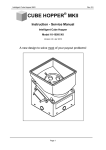
SERVICE MANUAL Version 1.6 Developed by SuzoHapp . Service manual Nearly 25 years of designing and manufacturing Casino Hoppers has resulted in this new product. Understanding the needs of both casinos and Slot machine manufacturers has led to this extremely durable and World’s most service friendly Casino hopper! New features: Planetary gearbox system provides following advantages: Maximum torque by minimal power consumption. Available in 12 or 24VDC Silent Operation. Unique bayonet connection for easy and economical motor replacement. Standard optical read out: Indirect optical read out. NPN, normally open (n/o). Optional: Indirect optical read out. NPN, normally closed (n/c). Optional: Second read out in the coin exit. Optics protected by cover against light (fraud) and dust. Other features: Easy accessible coin exit. Steel bearing offer stable disc rotation. Customised frame and cup specifications possible. All wear and tear parts such as pin and shelf wheel are 100% compatible with older generations STC hoppers. Easy to integrate for manufacturers who use older generation STC casino Hoppers. Applicable coin sizes: 18.00-38.09mm Pay out speed: <31mm coins: 450 coins per minute >31mm coins: 250 coins per minute All Excel hoppers can be supplied with customised wiring, with choice of strobe pins for low and / or high level detection Control boards: (optional) Part no. 14-0500-1 intelligent control board 24Vdc with direct start mode, logic Hi start mode, pulse mode and RS232 serial mode. Part no. 14-0500-2 intelligent control board 24Vdc with direct start mode, logic Lo start mode, pulse mode and RS232 serial mode. Part no. 14-0505-1 intelligent control board 12Vdc with direct start mode, logic Hi start mode, pulse mode and RS232 serial mode. Part no. 14-0505-1 intelligent control board 12Vdc with direct start mode, logic Hi start mode, pulse mode and RS232 serial mode. Part no. 14-0500-4 anti-jam control board 24Vdc to solve most of the possible coin jams during operation. Periodic maintenance (Warning: Before removing or installing the hopper make sure that power is switched off!) Maintenance recommended in six months interval. 1. Clean the optical sensor. 2. Clean the hopper knife and remove all dirt, especially on the route of coins, on the shelf wheel, the pinwheel around the area of the pins and the coin outlet. Inspection, recommended once in a year 1. Disassembling the coin cup of the hopper, in case of a non-metal cup check for any cracks or brakes. 2. Inspect the hopper knife for wearing and the correct position! For adjustments see fig.1 3. Inspect the hopper wiper for the correct position. The position of the wiper is very important for a correct payout! If necessary adjust it, see fig. 2 4. Inspect the rubber agitator. 5. Inspect the coin level, check the moment of the switch or check if the coin level probe is securely fastened. 6. Inspect cabling harness for damage, and if necessary tighten cables back on the harness. 7. Assembling coin cup with the 4 screws, springs and bushings back on the wheelhouse. 8. Inspect if the hopper slides gently in and out of the slot machine. Check the hopper and connector for proper function. Warning! Do not use any kind of lubrication on the hopper. After inspection and maintenance check the function of the hopper. For testing using the test mode of the slot- machine. Consult the manual or the slot-manufacturer for further instructions. Power Consumption: Voltage Unloaded 24VDC 0.25 Amp 12VDC 0.30 Amp Maximum torque of the motor 24V - 31RPM load 6kg N-m 24V - 21RPM load 12kg N-m Loaded 0.50 Amp 0.70 Amp Stall auto reverse 1.5 Amp 1.6 Amp 12V - 31RPM load 5kg N-m 12V - 21RPM load 11kg N-m Operating temperature: -10° to + 60°C This service manual is intended only to assist the reader in the use of this product. Therefore Suzo international shall not be held liable for any loss or damage whatsoever arising from the use of any information or particulars in or any commission from this manual or any incorrect use of the product. 1 Adjustments of the excel hopper Adjustment of the hopper with standard knife Loosen the two screws “A” move the tip of the knife against the pinwheel and the top of the shelfwheel. Lightly hold the knife on the shelfwheel and tighten the two screws “A” 5,5 Newton. Rotate the pinwheel and check there is no space between the shelfwheel and the knife in any position. A Adjustment of the hopper with full metal knife Loosen the two screws “A” move the tip of the knife against the pinwheel and the top of the shelfwheel. Turn the pinwheel at least one cycle and tighten the two screws “A” 5,5 Newton. Rotate the pinwheel and shelfwheel and the knife in any position. Fig: 1 Adjustment of the coin-wiper B C Position a coin under the wiper, make sure that the top of the wiper is equal to the top of the coin. Slightly loosen the two screws “B and C” - see fig 2. Move the wiper edge up to the coin. The edge should be close to the coin, app. 0,5 mm. Never let the wiper touch the coin! Tighten first the screw “B”, constantly checking the position of the wiper to the coin. Tighten screw “C” and check the final position. Do not over-tighten the screws B en C! Fig: 2 2 2 Disassembling the hopper. 1 1. Remove the 4 screws, which holds the hopper cup to the wheelhousing. 2 Remove the hopper cup and spring which is mounted on the right side of pivot pin. 3 4 3. Remove the 2 hexagon bolts, which holds the wiper, and remove the wiper. 4. Remove the 2 hexagon bolts, which holds the coin chute, and remove the coin chute and knife. 5 5. Remove the 2 Philips screws, which holds the coin deflector, and remove the coin deflector. 5 6. Remove the Philips screw, and spring in the centre of the disc. The disc assembly is now free floating in the hopper, remove the assembly by pulling on the agitator and lift it from the motor shaft. 3 7 7. Remove the 3 hex key screws, and disassemble the whole disc to make the new requested combination. 8 8. Take requested pinwheel, shelf-wheel and agitator, and mount the 3 screws back in position. 9 9. Put the disc assembly back on the hopper. The disc only fits 2 ways into the driver pin. 10. Place the spring liner in position around the disc, make sure the 10 end of the spring liner fits correct in the upper part on the wheelhousing. Finish the reassembling by reversing step 5, 4, 3, 2 and 1 of the disassembling description. 4 16-5038-XX DRAW. NR. PART NUMBER DESCRIPTION PCS 1 2 3 4 5 6 7 8 9 10 11 12 13 14 15 16 17 18 19 20 14-0400 5040-191 14-0140 SEE PART LIST G SEE PART LIST H 1050-242 14-0345 14-0085 14-0890-1 14-0470 0052-276 0081-006 61-2257-31 14-0720-6 14-0365 14-0440 1051-040 150-025-220 150-012-120 150-012-420 PIVOT ROD E WASHER BLACK (DIN 6799) SPRING LINER METAL STAR SUPPORT AGITATOR CUP LINER M5 TENSILOCK NUT EXTENSION SPRING COIN BAFFLE MEDIUM SCOOP EXTENSION AINS LEVELSENSOR PIN ISOLATION SLEEVE 5.2X7.9X1 ISOLATION WASHER 8.1X14X1 TAB 6.3MM BRASS HOLE 5.3MM 45GR HOPPER CUP 2 PCS STANDARD BLUE SPRING HEAVY MOUNT M5 EXT. STAR LOCKWASHER YELLOW M5X25 SCREW PHILL. PAN HD YELLOW M5X12 SCREW PHILL. PAN HD YELLOW M5X12 SCREW PHILL.FLAT HD YELLOW 1 2 1 1 1 9 1 1 1 1 1 1 2 1 2 4 4 4 3 2 21 14-0335 SPRING LIGHT Version 1.0 DRAW. NR. 22 23 24 25 26 27 28 29 30 31 32 33 34 35 36 37 38 39 40 41 2 * SEE LIST 14-1175 5 2-12-2003 PART NUMBER 14-0075 150-010-120 250-008-700-7 14-0025 14-0035 240-010-700-7 14-0960-14 240-008-700-7 14-1022 14-0015 14-0051 14-0009 14-0045 14-0355 14-0500-1 22-0087 22-0068-1 22-0068-3 14-0501-2 14-1175-1* DESCRIPTION SCOOP SUPPORT BRACKET M5X10 SCREW PHILL. PAN HD YELLOW M5X8 BOLT HX. HD. TAPT. FL. YELLOW RIGHT SIDE MOUNTING BRACKET PIVOT BRACKET M4X10 BOLT HX. HD. TAPT FL. YELLOW CABLE LOOM AINS M4X8 BOLT HX. HD. TAPT FL. YELLOW CONNECTOR BRACKET AMP 12 PINS LEFT SIDE MTG BRACKET BOTTOM GRIP PLATFORM 2MM SPRING MOUNT COMPRESSION SPRING HOPPER CONTROL BOARD PCB HOLDER SELF ADHESIVE CABLE CLIP 6MM SELF ADHESIVE WIRE CLIP 6X2MM INTERF.CABLE FOR PCB HOPPER PROBE EXCEL WHEELHOUSE ASSEMBLY PCS 1 3 10 1 1 2 1 4 1 1 1 1 1 1 1 3 2 3 1 1 14-1175 DRAW. NR. 1A 2A 3A 4A 5A 6A 7A 8A 9A 10A 11A 12A 13A 14A 15A PART NUMBER 14-1155 150-020-422 14-1145 14-1140 150-012-700-1 14-0070 14-0416 14-0590 150-050-422 240-008-220 1042-145 See part list A 14-1100 150-010-120 1055-160 DESCRIPTION SENSOR COVER M5X20 SCREW PH.FL.HD. ROCK AND ROLLER ASSY OPTO SENSOR M5x12 TENSILOCK BOLT YELLOW WIPER BEARING PIN BEARING 6X19X6MM M5x50 FL.HD.MOTOR SCREW M4X8 SCREW PH. PAN. HD.YELLOW M4 WASHER 4.2X14X0.5 MOTOR ASSY 24VDC EXCEL WHEELHOUSING M5X10 SCREW PH. PAN. HD.YELLOW M5 WOODWASHER YELLOW PCS 1 1 1 1 2 1 4 4 4 1 1 1 1 2 2 Version 1.0 DRAW. NR. 16A 17A 18A 19A 20A 21A 22A 23A 24A 25A 26A 27A 28A 29A 30A 07-11-2003 PART NUMBER 150-025-700 1050-050 140-008-420 14-0095 See part list B See part list C 15-016-700-1 199-025-040 14-0110 See part list D See part list E 14-0571 See part list F 14-0365 150-010-223-7 DESCRIPTION M5X25 BOLT HX. HD. YELLOW M5 NUT HEX. YELLOW M4X8 SCREW PH. FL. HD. YELLOW COIN DEFLECTOR HOPPER KNIFE OUTLET COVER M5X16 TENSILOCK BOLT YLLOW M10X25 SCREW HX.HD. IMBUS DRIVING HUB PINWHEEL SHELFWHEEL AGITATOR WITH BUSHINGS M5 SCREW HX HD. HUB SPRING M5X10X13 SCREW PH.HD.FLANGE NICK NR. MIN MAX Part A Part B Part C Part D Part E Part F Part G Part H -XX mm mm motor knife Outlet cov. pinwheel shelfwheel M5 Screw Met. Supp. cup liner -1 18.00 18.99 14-1115 14-0281 14-0065 14-0116 14-0130-1505 150-020-931 not used not used - 19.00 20.09 14-1115 14-0281 14-0065 14-0116 14-0130-1465 150-020-931 not used not used -8 20.10 22.09 14-1115 14-0281 14-0065 14-0116 14-0130-1425 150-020-931 not used not used -12 22.10 24.89 14-1115 14-0281 14-0065 14-0115 14-0130-1370 150-020-931 not used not used -2 24.90 25.89 14-1115 14-0281 14-0065 14-0115 14-0130-1350 150-020-931 not used not used -5 25.90 27.89 14-1115 14-0281 14-0065 14-0115 14-0130-1310 150-020-931 not used not used -3 27.90 31.09 14-1115 14-0281 14-0066 14-0115 14-0130-1235 150-020-931 not used 14-0145 -7 31.10 31.99 14-1115 14-0281 14-0066 14-0112 14-0130-1235 150-020-931 not used 14-0145 -9 32.00 33.09 14-1115 14-0281 14-0066 14-0112 14-0130-1205 150-020-931 not used 14-0145 -10 33.10 35.09 14-1135 14-0296 14-0067 14-0112 14-0130-1165 150-025-522 14-0580 14-0145 -6 35.10 36.99 14-1135 14-0296 14-0067 14-0012 14-0130-1125 150-025-522 14-0580 14-0145 -4 37.00 38.09 14-1135 14-0296 14-0067 14-0112 14-0130-1075 150-025-522 14-0580 14-0145 6 PCS 1 1 2 1 1 1 2 1 1 1 1 1 3 1 1 Configuration for Euro coins: 5 € cent (21.25 mm) Pinwheel 16 pin for diameter from 18.00 - 22.09 mm Shelfwheel 142,5mm for coins 20.10 - 22.09 mm Knife for coins 18.0 - 33.09 mm (metal insert) Motor 24 VDC 31 RPM Outlet cover for coins 18.00 - 27.89 mm 10 € cent (19.75 mm) Pinwheel 16 pin for diameter from 18.00 - 22.09 mm Shelfwheel 146.5mm for coins 19.0 - 20.0mm Knife for coins 18.00 - 33.09 mm metal inserts Motor 24 VDC 31 RPM Outlet cover for coins 18.00 - 27.89 mm Part no. 14-0116 14-0130-1425 14-0281 14-1115 14-0065 14-0116 14-0130-1465 14-0281 14-1115 14-0065 20 € cent (22.25 mm), 50 € cent (24.25 mm) and 1 € (23.25mm) Pinwheel 15 pins for diameter from 22.10 - 31.09 mm 14-0115 Shelfwheel 136.5mm for coins 22.10 - 24.89 14-0130-1370 Knife for coins 18.00 - 33.09 mm metal inserts 14-0281 Motor 24 VDC 31 RPM 14-1115 Outlet cover for coins 18.00 - 27.89 mm 14-0065 2 € (25.75 mm) Pinwheel 15 pin for diameter from 22.10 - 31.09 mm Shelfwheel 135.0mm for coins 24.90 - 25.89mm Knife for coins 18.00 - 33.09 mm metal inserts Motor 24 VDC 31 RPM Outlet cover for coins 18.00 - 27.89 mm 14-0115 14-0130-1350 14-0281 14-1115 14-0065 Configuration for US coins: Nickel (21.21mm) Pinwheel 16 pin for diameter from 18.00 – 22.09mm Shelfwheel 142,5 for coin 20.10 – 22.09mm Knife for coins 18.00 –33.09mm metal inserts Motor 24 VDC 31 RPM Outlet cover for coins 18.00 – 27.89mm 14-0116 14-0130-1425 14-0281 14-1115 14-0065 Quarter (24,23mm) Pinwheel 15 pin for diameter 22.10 – 31.09mm Shelfwheel 136,5 for coin 22.10 – 24.89mm Knife for coins 18.00 –33.09mm metal inserts Motor 24 VDC 31 RPM Outlet cover for coins 18.09 – 27.89mm 14-0115 14-0130-1370 14-0281 14-1115 14-0065 Hopper denomination conversions Pinwheels: Part no 16 pin for diameter from 18.00 - 22.09 mm 15 pin for diameter from 22.10 - 31.09 mm 12 pin for diameter from 31.10 - 38.00 mm Shelfwheel: 107.5 mm / coins 37.00 - 38.00 mm 112.5 mm / coins 35.10 - 36.99 mm 116.5 mm / coins 33.10 - 35.09 mm 120.5 mm / coins 32.00 - 33.09 mm 123.5 mm / coins 27.90 - 31.99 mm 131.0 mm / coins 25.90 - 27.89 mm 135.0 mm / coins 24.09 - 25.89 mm 136.5 mm / coins 22.10 - 24.89 mm 142.5 mm / coins 20.10 - 22.09 mm 146.5 mm / coins 19.00 - 20.09 mm 150.5 mm / coins 18.00 - 18.99 mm 14-0116 14-0115 14-0112 14-0130-1075 14-0130-1125 14-0130-1165 14-0130-1205 14-0130-1235 14-0130-1310 14-0130-1350 14-0130-1370 14-0130-1425 14-0130-1465 14-0130-1505 Motors: Motor 12V DC 31 RPM / coins 18.00 - 33.09 mm Motor 12V DC 21 RPM / coins 33.10 - 38.09 mm Motor 24V DC 31 RPM / coins 18.00 - 33.09 mm Motor 24V DC 21 RPM / coins 33.10 - 38.09 mm 14-1110 14-1130 14-1115 14-1135 Knifes: Knife for coins 18.00 - 33.09 mm Metal knife for coins 33.10 - 38.09 mm 14-0281 14-0296 Outlet covers: Outlet cover for coins 18.00 - 27.89mm Outlet cover for coins 27.90 - 33.09 mm Outlet cover for coins 33.10 - 38.09 mm 14-0065 14-0066 14-0067 Cup liner: For standard cup, coins >27.90 mm For wide and narrow cup, coins >27.90mm 14-0145 14-0800 Agitator: Standard rubber agitator 14-0571 Dollar token (37.2mm) Pinwheel 12 pin for diameter from 31.10 – 38.09mm 14-0112 Shelfwheel 107,5 for coin 37.00 – 38.09mm 14-0130-1075 Metal Knife for coins 33.10 –38.09mm 14-0296 Motor 24 VDC 21 RPM 14-1135 Outlet cover for coins 33.10> 14-0067 Cup liner for standard cup, used for coins >27.90mm 14-0145 Metal star on agitator for coins >33.10mm 14-0580 This document is the private property of Suzo international and may not be reproduced in part or in total by means, electronic or otherwise without the written permission of Suzo international. Suzo International does not accept any errors contained in this document. eu.suzohapp.com 7