1
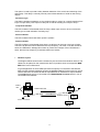
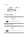
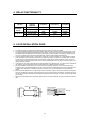
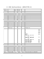
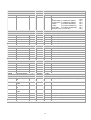
LD220
DUAL LOOP DETECTOR WITH MODBUS
COMMUNICATIONS
USER MANUAL
P.O.Box 24
STANFIELD 3613
SOUTH AFRICA
18/08/2005 V3.0
Tel:
Fax:
Email:
Web:
+27 (031) 7028033
+27 (031) 7028041
[email protected]
www.proconel.com
TABLE OF CONTENTS
1.
AN OVERVIEW OF THE LD220 MODBUS SYSTEM ............................ 3
2.
LD220 HARDWARE ............................................................................... 5
2.1
2.2
SPECIFICATIONS ............................................................................... 5
WIRING................................................................................................ 6
3.
DIAGNOSTICS ....................................................................................... 7
4.
RELAY FUNCTIONALITY ...................................................................... 8
5.
LOOP INSTALLATION GUIDE .............................................................. 8
6.
DATA ADDRESSES ............................................................................... 9
6.1
LD220 - DUAL CHANNEL DETECTOR ( MODULE TYPE = 35) ................. 10
2
1. AN OVERVIEW OF THE LD220 MODBUS SYSTEM
The LD220 is a series of dual channel inductive loop detectors. The use of microprocessor
and surface mount technology enables a large number of functions to be incorporated into a
small package. The LD220 is compatible with most dual channel detectors on the market and
is easy to set-up and install. All configuration is done through the communications port.
The LD220 is supplied with a RS485 communications port. The LD220R is supplied with a
RS232 communications port.
Typical applications in the parking and access control environments are safety loops, arming
loops and entry or exit loops and direction logic with counting.
The LD220 consists of an inductive loop detector with an integral RS485 communications
port. The unit has been developed to enable remote monitoring and control of the loop
detector over a RS485 network. The communications allows access to internal setup
parameters such as sensitivity, timers, as well as counters. The LD220 can be multi-dropped
on the RS485 network with other detectors and logic units, or linked to a PC running software
for configuration and monitoring of the parking system. Non volatile memory is used to store
counters and all configuration parameters.
Standard features of the logic on the unit are :
· RS485 Communications Port.
The RS485 communications port enables up to 127 detectors to be networked on a single
twisted pair cable. The LD220 communicates using the Modbus protocol in Binary mode. All
configuration data is held in modbus registers and can be setup by a PC or PLC on the
network.
· Selectable Pulse Time.
This feature sets the length of time that the pulse relay will be energized.
· Pulse Relay Selection.
The Pulse relay may be configured to energize on detection of a vehicle or when the vehicle
leaves the loop.
· Sensitivity Boost.
This feature sets the undetect level to maximum sensitivity and is used to prevent loss of
detection of high-bed vehicles.
· Switch selectable Sensitivity.
The detect sensitivity is the minimum change in inductance required to produce a detect
output. (%ΔL/L) .
· Switch selectable Frequency.
The frequency of the loop is determined by the inductance of the loop and the frequency
switch setting. If the frequency switch is on, the frequency is reduced. It may be necessary to
change the frequency to prevent cross-talk between adjacent loops.
· Filter Option.
3
This option is used to provide a delay between detection of the vehicle and switching of the
output relay. This delay is normally used to prevent false detection of small or fast moving
objects.
· Direction Logic.
This feature enables the detector to give a pulse output on relay1 for a vehicle traveling from
loop1 to loop2 and a pulse output on relay2 for a vehicle traveling from loop2 to loop1.
· Loop Fault Indicator.
This LED Indicator is illuminated when the loop is either open circuit or short circuit and is
used to give a visual indication of a faulty loop.
· Power Indicator.
This LED Indicator illuminates when power is present.
· Detect Indicator.
This LED Indicator is illuminated when there is a vehicle over the loop or the loop is faulty.
This LED can also be used to determine the loop frequency. On reset, count the number of
times the LED flashes. Multiply this number by 10KHz.For example: if the LED flashes 6
times, then the loop frequency is between 60KHz and 70KHz.
•
Network Layout.
The diagram below shows how the LD220 may be connected to a Modbus network. The
LD220 can be placed on the network with other I/O products such as the popular MODMUX from Procon Electronics.
A typical application is where a PC (Personal Computer) is connected to the Network.
Many SCADA software packages support the MODBUS Master Protocol and can hence
retrieve data from the LD220 as well as Input Modules or send data to Output Modules.
The serial port of the PC is connected to an RS232/RS485 Converter which in turn is
connected to the Network.
PC
INPUTS
SERIAL
LINK
232/485
CONVERTER
8DI
MODBUS MASTER
MODBUS SLAVE
120 ohm Termination
8DO
OUTPUTS
LD220
I/O
4
2. LD220 HARDWARE
2.1 SPECIFICATIONS
POWER REQUIREMENT:
LD220 - 220VAC (+/- 15% ) 50Hz.
LD221 - 110VAC (+/- 15%) 60Hz.
LD222 - 12/24VAC/DC (+/- 15%).
RELAY OUTPUT: These outputs has are either a normally open or normally closed relay
contact rated at 0.5A/220VAC.(select with internal jumper)
INDICATORS: LED indicator's show: Power, Detect state and Loop Fault.
DETECTOR TUNING RANGE: 15 - 1500 uH.
FREQUENCY: Single step adjustable (internal jumper).
PROTECTION: Loop isolation transformer with lightening protection.
CONNECTOR: 11 Pin Connector on rear of unit.
DIMENSIONS: 80mm (HIGH) X 40mm (WIDE) X 79mm (DEEP)
OPERATING TEMPERATURE: -40°C to +80°C
STORAGE TEMPERATURE: -40°C to +85°C
HUMIDITY: up to 95% non condensing
Complies with EMC Directive 89/336/EEC and Low Voltage Equipment Directive 73/23/EEC.
5
2.2 WIRING
7
10
PRESENCE /
PULSE RELAY
OUTPUT 1
11
PRESENCE /
PULSE RELAY
OUTPUT 2
8
TWISTED
3
CABLE
4
TWISTED
5
CABLE
6
LOOP 1 INPUT
LOOP 1
LOOP 2 INPUT
LOOP 2
LIVE 220VAC /12VAC/DC
1
NEUTRAL
/ 12VAC/DC
2
EARTH
9
POWER INPUT
Comms (RJ45) – RS485 (LD220)
Pin
Name
Function
1
N/C
Not used (no connect)
2
3
485
485
+ Line of 485 Comms
- Line of 485 Comms
4
N/C
Not used (no connect)
View From Cable side of connector (Looking ‘into’ hole)
1234
Comms (RJ45) – RS232 (LD220R)
Pin
Name
Function
1
N/C
Not used (no connect)
2
3
TXD
RXD
RS232 Transmit
RS232 Receive
4
GND
RS232 Common
View From Cable side of connector (Looking ‘into’ hole)
1234
6
3. DIAGNOSTICS
SYMPTOM
POSSIBLE CAUSE
SOLUTION
The POWER LED is
not on.
No power supply voltage on the Check that the power supply is correctly wired to
input.
the detector. (PINS 1 and 2)
The DETECT LED
flashes erratically.
There may be a poor
connection in the loop or loop
feeder.
The DETECT LED
randomly stays on.
The detector may be experiencing
crosstalk vith the loop of an
adjacent detector.
Faulty loop or loop feeder
wiring.
Check all wiring. Tighten screw terminals. Check for
broken wires.
Try changing frequencies using the frequency switch.
Put the detector with the larger loop onto low frequency
and the detector with the smaller loop onto high
frequency.
Check the wiring. Tighten screw terminals. Check
for pinched or bent wires. Is the feeder wire
twisted?
Check for cracks in the road surface near the loop.
Movement of the loop in the
ground.
The LOOP FAULT LED The loop inductance is to small
is flashing.
or the loop is short circuit.
The LOOP FAULT LED The loop inductance is to large
is permanently
or the loop is open circuit.
illuminated.
Check that there is no short circuit on the loop
feeder wiring or the loop. If there is no short circuit
then the inductance is to small and more turns of
wire should be added to the loop.
Check that there is electrical continuity on the loop.
This can be done using a multimeter on the ohms
range (< 5 Ω). If the loop inductance is to large then
try reducing the number of turns.
7
4. RELAY FUNCTIONALITY
RELAYS
PRESENCE
RELAY
PULSE RELAY
NO VEHICLE
LOOP FAULTY
NO POWER
N/O
VEHICLE
PRESENT
CLOSED
OPEN
CLOSED
CLOSED
N/C
OPEN
CLOSED
OPEN
OPEN
N/O
PULSE CLOSED
OPEN
CLOSED
CLOSED
N/C
PULSE OPEN
CLOSED
OPEN
OPEN
5. LOOP INSTALLATION GUIDE
1. The detector should be installed in a waterproof housing as close to the loop as possible.
2
2. The loop and feeder should be made from insulated copper wire with a minimum cross-sectional area of 1.5mm .
The feeder should be twisted with at least 20 turns per metre. Joints in the wire are not recommended and must
be soldered and made waterproof. Faulty joints could lead to incorrect operation of the detector. Feeders which
may pick up electrical noise should use screened cable, with the screen earthed at the detector.
3. The loop should be either square or rectangular in shape with a minimum distance of 1 metre between opposite
sides. Normally 3 turns of wire are used in the loop. Large loops with a circumference of greater than 10 metres
should use 2 turns while small loops with a circumference of less than 6 metres should use 4 turns. When two
loops are used in close proximity to each other it is recommended that 3 turns are used in one and 4 turns in the
other to prevent cross-talk.
4. Cross-talk is a term used to describe the interference between two adjacent loops. To avoid incorrect operation of
the detector, the loops should be at least 2 metres apart and on different frequency settings.
5. For loop installation, slots should be cut in the road using a masonry cutting tool. A 45o cut should be made
across the corners to prevent damage to the wire on the corners. The slot should be about 4mm wide and 30mm
to 50mm deep. Remember to extend the slot from one of the corners to the road-side to accommodate the
feeder.
6. Best results are obtained when a single length of wire is used with no joints. This may be achieved by running the
wire from the detector to the loop, around the loop for 3 turns and then back to the detector. The feeder portion of
the wire is then twisted. Remember that twisting the feeder will shorten its length, so ensure a long enough feeder
wire is used.
7. After the loop and feeder wires have been placed in the slot, the slot is filled with an epoxy compound or bitumen
filler.
TRAFFIC
300mm
DIRECTION
300mm
1M
45O
ROAD SURFACE
SLOT
SEALANT
ROAD
EDGE
30-50 mm
WIRES
4mm
FEEDER
8
6. DATA ADDRESSES
The data in the modules is stored in registers. These registers are accessed over the network
using the MODBUS communication protocol.
The MODBUS mode used is the RTU mode with the following set-up:
BAUD RATE
DATA BITS
PARITY
STOP BITS
9600
8
NONE
1
There are 4 types of variables which can be accessed from the module. Each module has
one or more of these data variables.
Type
Start Address
Variable
1
2
3
4
00001
10001
30001
40001
Digital Outputs
Digital Inputs
Input registers (Analog)
Output registers (Analog)
Note: Due to the limited buffer memory size in the modules, the Modbus
message length must be limited to 8 consecutive read or write registers.
If more registers are required then a new poll group must be added for
the next 8 registers.
9
6.1 LD220 - Dual Channel Detector
Modbus
Address
Register Name
10001
Digital Input 1
( MODULE TYPE = 35)
Low
Limit
High
Limit
Access
0
1
R
Comments
Loop1 Fault Status.
10002
Digital Input 2
0
1
R
Loop1 Detect Status.
10003
Digital Input 3
0
1
R
Loop2 Fault Status.
10004
Digital Input 4
0
1
R
Loop2 Detect Status.
10005
Digital Input 5
0
1
R
Loop1 Error – Open circuit.
10006
Digital Input 6
0
1
R
Loop1 Error – Short circuit.
10007
Digital Input 7
0
1
R
Loop2 Error – Open circuit.
10008
Digital Input 8
0
1
R
Loop2 Error – Short circuit.
00009
Digital Output 1
0
1
R/W
Relay 1
00010
Digital Output 2
0
1
R/W
Relay 2
30001
S/W Version /
Module Type
N/A
N/A
R
High Byte = Software Version
Low Byte = 35
30002
Digital I/O
N/A
N/A
R
0,
0,
0,
0,
0,
0,
Relay 2
Relay 1
Loop2 Error – Short circuit
bit 7
Loop2 Error – Open circuit
Loop1 Error – Short circuit
bit 5
Loop1 Error – Open circuit
Loop2 Detect Status
Loop2 Fault Status
Loop1 Detect Status
Loop1 Fault Status
Real Time Clock
40003
Seconds
0
65535
R/W
40004
Minutes
0
65535
R/W
"
40005
Hours
0
65535
R/W
"
40006
Days
0
65535
R/W
"
40007
Date
0
65535
R/W
"
40008
Month
0
65535
R/W
"
bit 15
bit 14
bit 13
bit 12
bit 11
bit 10
bit 9
bit 8
bit 6
bit 4
bit 3
bit 2
bit 1
bit 0
40009
Year
0
65535
R/W
40010
Counter 1 LSB
0
65535
R/W
Counter MSB and LSB combine to give a 32 bit
40011
Counter 1 MSB
0
65535
R/W
Counter with range 0 to 4294967295.
10
"
40012
Counter 2 LSB
0
65535
R/W
"
40013
Counter 2 MSB
0
65535
R/W
"
40014
Node ID
0
65535
R/W
Network ID (default = 254)
40015
Mode
0
65535
R/W
0,
0,
pulse relay2 (1=undetect,0=detect)
pulse relay1 (1=undetect,0=detect)
relay2
(1=pulse,0=presence)
relay1
(1= pulse,0=presence)
pres relay (1=modbus,0=detector)
direction logic (1=on,0=off)
40016
Det Sensitivity 1
0
65535
R/W
( X0.01%)
40017
Det Sensitivity 2
0
65535
R/W
( X0.01%)
40018
UnDet Sens 1
0
65535
R/W
( X0.01%)
40019
UnDet Sens 2
0
65535
R/W
( X0.01%)
40020
Pulse Time 1
0
65535
R/W
( X10ms)
40021
Pulse Time 2
0
65535
R/W
( X10ms)
40022
Filter 1
0
65535
R/W
( X10ms)
40023
Filter 2
0
65535
R/W
( X10ms)
40024
UnDet Time 1
0
65535
R/W
( X10ms)
( X10ms)
bit 7
bit 6
bit 5
bit 4
bit 3
bit 2
bit 1
bit 0
40025
UnDet Time 2
0
65535
R/W
40026
Reset Seconds
0
65535
R/W
40027
Reset Minutes
0
65535
R/W
40028
Reset Hours
0
65535
R/W
40029
Reset Days
0
65535
R/W
40030
Reset Date
0
65535
R/W
40031
Reset Month
0
65535
R/W
40032
Reset Year
0
65535
R/W
40033
Reset Counter
0
65535
R/W
40034
Pwr_Down Cntr
0
65535
R/W
40035
Re-Tune Cntr 1
0
65535
R/W
40036
Re-Tune Cntr 2
0
65535
R/W
40037
Not Used
0
65535
R/W
40038
Loop1Freq.MS
B
0
65535
R/W
Frequency MSB and LSB combine to give a 32
40039
Loop1Freq.
LSB
0
65535
R/W
bit value.
40040
Loop2Freq.MS
B
0
65535
R/W
“
40041
Loop2Freq.
LSB
0
65535
R/W
“
40042
Delta 1
0
65535
R/W
40043
Delta 2
0
65535
R/W
40044
Delta 1 MIN
0
65535
R/W
40045
Delta 2 MIN
0
65535
R/W
11
Change in loop inductance.
“
Smallest change in inductance.
“


![取扱説明書[SQ-LD220] (981.14 KB/PDF)](http://vs1.manualzilla.com/store/data/006714468_3-aeb854a3ef10cdb48d9d4e97b3e35cf3-150x150.png)