1
kÉï=~ë=çÑW==
MTKOMNO
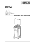
`bob`=^`
pÉêîáÅÉ=j~åì~ä
båÖäáëÜ
Service manual
Sirona Dental Systems GmbH
Service Manual CEREC AC
Table of contents
1
2
3
4
2
General information..................................................................................................
5
1.1
General information.......................................................................................
5
1.2
Additional information....................................................................................
6
Troubleshooting........................................................................................................
7
2.1
System cannot be switched on .....................................................................
8
2.2
PC not booting correctly ................................................................................
11
2.3
PC does not respond when switched on, PC power supply does not start ...
14
2.4
Other PC faults..............................................................................................
15
2.5
No monitor display ........................................................................................
17
2.6
Incorrect monitor display format size ............................................................
18
2.7
Monitor: Color depth/number of grayscales is insufficient.............................
18
2.8
Trackball not functioning ...............................................................................
20
2.9
Trackball buttons not functioning ..................................................................
22
2.10
Footswitch not functioning.............................................................................
23
2.11
Keyboard not functioning /defective ..............................................................
24
2.12
No camera image (Bluecam) ........................................................................
25
2.13
No camera image (Omnicam) .......................................................................
26
2.14
Incorrectly adjusted optical impression (Bluecam) ........................................
28
2.15
Error messages during camera calibration (Bluecam) ..................................
29
2.16
Error messages during camera calibration (Omnicam).................................
30
2.17
LAN communication problems ......................................................................
32
2.18
WLAN communication problems ...................................................................
34
2.19
WLAN occasionally interrupted .....................................................................
35
Settings ....................................................................................................................
36
3.1
Changing from right-handed to left-handed operation ..................................
36
Repair.......................................................................................................................
38
4.1
General information on assembly .................................................................
38
4.2
Covers ...........................................................................................................
39
4.2.1 Removing and inserting the back panel .............................................
39
4.2.2 Removing and inserting the front panel .............................................
40
62 34 269 D3492
D3492.076.01.03.02 07.2012
Sirona Dental Systems GmbH
4.2.3 Replacing the camera holder ............................................................
41
4.2.4 Replacing the upper side cover.........................................................
42
Electrical and electromechanical components .............................................
43
4.3.1 Monitor ..............................................................................................
43
4.3.1.1 Replacing the LCD monitor .............................................................
43
4.3.1.2 Replacing the tilt joint ......................................................................
44
4.3.1.3 Replacing the DVI cable..................................................................
48
4.3.1.4 Replacing the monitor support ........................................................
51
4.3.2 PC of the acquisition unit ..................................................................
55
4.3.2.1 Removing and inserting the PC.......................................................
55
4.3.2.2 Replacing the hard drive .................................................................
57
4.3.2.3 Boards .............................................................................................
57
4.3.2.4 Replacing the loudspeakers ............................................................
59
4.3.2.5 Replacing fans (CEREC AC with Bluecam) ....................................
60
4.3.2.6 Replacing fans (CEREC AC with Omnicam)...................................
61
4.3.2.7 Replacing the power supply unit .....................................................
62
4.3.3 Control unit........................................................................................
65
4.3.3.1 Removing and inserting the control unit ..........................................
65
4.3.3.2 Replacing the trackball button board...............................................
66
4.3.3.3 Replacing the keyboard...................................................................
67
4.3.3.4 Replacing the optical trackball.........................................................
68
4.3.4 Replacing the DVD drive...................................................................
69
4.3.5 Fuses ................................................................................................
70
4.3.5.1 Replacing the main fuse..................................................................
70
4.3.5.2 Replacing fuse F3 ...........................................................................
71
4.3.6 Replacing the battery ........................................................................
71
4.3.7 Replacing the isolating transformer...................................................
72
Mechanical components...............................................................................
74
4.4.1 Replacing the air filter .......................................................................
74
4.4.2 Replacing the foot pedal ...................................................................
74
4.4.3 Replacing the footswitch ...................................................................
75
4.4.4 Replacing the flap for the DVD drive.................................................
76
4.4.5 Replacing the handle ........................................................................
77
Circuit diagrams.......................................................................................................
79
5.1
CEREC AC with Bluecam ............................................................................
80
5.2
CEREC AC with Omnicam ...........................................................................
81
4.3
4.4
5
62 34 269 D3492
D3492.076.01.03.02
07.2012
3
båÖäáëÜ
Service Manual CEREC AC
Sirona Dental Systems GmbH
Service Manual CEREC AC
6
4
Re-test......................................................................................................................
82
6.1
When is the re-test carried out? ....................................................................
82
6.2
Description of device type .............................................................................
82
6.3
To be carried out on completion of the test ...................................................
82
6.4
What the test steps involve ...........................................................................
82
6.4.1 Visual inspection ................................................................................
82
6.4.2 Protective ground wire resistance ......................................................
82
6.4.3 Device leakage current ......................................................................
83
6.4.4 Insulation resistance ..........................................................................
83
6.4.5 Functional test....................................................................................
83
62 34 269 D3492
D3492.076.01.03.02 07.2012
Sirona Dental Systems GmbH
1 General information
Service Manual CEREC AC
1.1 General information
1
General information
General information
1.1 General information
General information
Nominal line voltage ranges
(CEREC Omnicam)
Wireless phone interference with
medical electrical equipment:
The acquisition unit works in the following ranges:
Rated line voltage for Europe
230 VAC / 50Hz
Rated current for Europe
1.5 A
Rated line voltage for the USA
115VAC / 60Hz
Rated current for the USA
2,7 A
Rated line voltage for Japan
100VAC / 50Hz and 60Hz
Rated current for Japan
3,0 A
The acquisition unit works in the following ranges:
Rated line voltage
100-240 VAC / 50-60Hz
Rated current
4.7-1.8 A
båÖäáëÜ
Nominal line voltage ranges
(CEREC Bluecam)
NOTICE
To ensure safe operation of medical electrical equipment, the use of
mobile wireless phones in practice or hospital environments is
prohibited.
ESD warning label
ESD warning label
CAUTION
Connector pins or sockets bearing ESD warning labels must not be
touched or interconnected without ESD protective measures.
ESD protective measures
ESD protective measures
ESD protective measures include:
● Procedures for preventing electrostatic charge build-up (e.g. air
conditioning, air moistening, conductive floor coverings and nonsynthetic clothing)
● Discharging the electrostatic charges of your own body on the frame
of the UNIT, the protective ground wire or large metallic objects
● Connecting yourself to ground using a wrist band.
Replacing parts
WARNING
Potentially lethal shock hazard when working near the power supply unit
Disconnect from the line power supply.
Check for zero potential.
Switch the unit off and disconnect the power plug before replacing parts.
The item numbers for ordering spare parts can be found in the spare parts
list.
62 34 269 D3492
D3492.076.01.03.02
07.2012
5
1 General information
Sirona Dental Systems GmbH
1.2 Additional information
Service Manual CEREC AC
The diagrams contained in the spare parts list provide a useful guide
when replacing parts.
Before replacing the boards, observe the ESD protective measures.
Disposal
Observe the information on disposal in the relevant operating
instructions.
Installation site
Observe the information on the installation site in the relevant operating
instructions.
1.2 Additional information
Additional information
In addition, you also require:
CEREC AC spare parts list
Order No.: „62 31 786“
CEREC AC Wiring Diagrams
Order No.: „62 33 162“
CEREC AC Operating Instructions with Bluecam
Order No.: „62 31 174“
CEREC AC Operating Instructions with Omnicam
Order No.: „62 81 136“
Documents:
Operating the MC XL via LAN (61 90 503)
Operating MC XL via WLAN in infrastructure mode, Restoring default
settings (61 90 560)
Tools
● TORX screwdriver, size 6; 8; 10; 20; 30
● Phillips screwdriver, size 1
● Blade screwdriver, insulated, sizes 2 and 3
● Universal pliers
● Flat pliers
Auxiliary tools & equipment
● Digital Multimeter, Accuracy Class 1
● Soldering tool for repairing cables
● Side cutting pliers
● Cable ties
● Teflon tape
● Fuses (recommended):
6
F1/F2 (2 pcs)
T8A H 250V
Order No.: 62 33 188
F3
T2,5A L 250V
Order No.: 46 57 656
62 34 269 D3492
D3492.076.01.03.02 07.2012
Sirona Dental Systems GmbH
2 Troubleshooting
Service Manual CEREC AC
2
Troubleshooting
Switching the unit off
Troubleshooting
NOTICE
Switching the unit off
båÖäáëÜ
Always switch the unit off before connecting a measuring instrument or
replacing parts.
62 34 269 D3492
D3492.076.01.03.02
07.2012
7
2 Troubleshooting
Sirona Dental Systems GmbH
2.1 System cannot be switched on
Service Manual CEREC AC
2.1 System cannot be switched on
System cannot be switched on
See next page.
8
62 34 269 D3492
D3492.076.01.03.02 07.2012
Sirona Dental Systems GmbH
2 Troubleshooting
2.1 System cannot be switched on
båÖäáëÜ
Service Manual CEREC AC
62 34 269 D3492
D3492.076.01.03.02
07.2012
9
2 Troubleshooting
Sirona Dental Systems GmbH
2.1 System cannot be switched on
Service Manual CEREC AC
A
B
B
ON button
A
115
Ready LED
230
A
B
C
D
A
Voltage selection insert
(only with
CEREC Bluecam)
C
Fuse module
B
Main fuse
D
Window
B
Fuse
Only with CEREC Bluecam
A B
A
10
Fuse holder
62 34 269 D3492
D3492.076.01.03.02 07.2012
Sirona Dental Systems GmbH
2 Troubleshooting
Service Manual CEREC AC
2.2 PC not booting correctly
2.2 PC not booting correctly
PC not booting correctly
båÖäáëÜ
A
B
A
DVI cable connected to
monitor
B
DVI cable connected to PC
Introductory sentence
To start, check the following:
● Are the keyboard, trackball and DVI cable connected to the monitor
on the PC slide-in module?
● Is the LED above the ON button yellow or green? See also System
cannot be switched on [ → 8].
62 34 269 D3492
D3492.076.01.03.02
07.2012
11
2 Troubleshooting
Sirona Dental Systems GmbH
2.2 PC not booting correctly
Service Manual CEREC AC
List of beep-tone error codes
Beep tone sequence
Cause of error
permanent
The graphic card is defective or has no power supply
Error messages during boot-up and possible causes of errors:
Beep tone sequence
Cause of error
Disk Boot Failure, insert System Disk and press Enter.
If the primary master disk was not found: Check the data
cable and voltage supply of the hard disk and the CD/
DVD drive.
Press a key to reboot.
Boot sector of hard disk cannot be found. Boot with
Restore CD. If this fails, replace the PC.
12
62 34 269 D3492
D3492.076.01.03.02 07.2012
Sirona Dental Systems GmbH
2 Troubleshooting
2.2 PC not booting correctly
båÖäáëÜ
Service Manual CEREC AC
62 34 269 D3492
D3492.076.01.03.02
07.2012
13
2 Troubleshooting
Sirona Dental Systems GmbH
2.3 PC does not respond when switched on, PC power supply does not start
Service Manual CEREC AC
2.3 PC does not respond when switched on, PC
power supply does not start
PC does not respond when switched on, PC power supply does not start
See next page.
14
62 34 269 D3492
D3492.076.01.03.02 07.2012
Sirona Dental Systems GmbH
2 Troubleshooting
2.4 Other PC faults
båÖäáëÜ
Service Manual CEREC AC
2.4 Other PC faults
Other PC faults
Case of defect/fault
How to detect / action to take
COM port not functioning
Try replacing the wireless interface with a cable connection.
If this fails, check whether the COM port is enabled in the BIOS. If it is, replace
the PC.
No mouse pointer displayed on
screen
Trackball defective or not connected.
No keyboard input possible
Keyboard (keyboard controller) defective or improperly connected.
Check to make sure this fault is not due to bent plug contacts.
62 34 269 D3492
D3492.076.01.03.02
07.2012
15
2 Troubleshooting
Sirona Dental Systems GmbH
2.4 Other PC faults
Service Manual CEREC AC
Case of defect/fault
How to detect / action to take
Network cannot be accessed
The upper LED at the network connection must be permanently lit green. If not:
● The network cable between the network card and the hub / switch is
defective.
● Hub / switch defective (check whether other PCs connected to hub / switch
can access the network).
The "TX Data Act" LED flashes during data communication via the network.
CD-ROM / DVD-ROM missing in
list of system drives (Explorer)
No audio playback
Data cable and/or voltage supply disconnected and/or defective.
If this is the case, the drive is defective. Test via BIOS: It must be possible to
select the drive.
Only a musical CD or only a wave file cannot be played back:
● Check the software settings
● Wrong sound card driver installed.
● Cable between CD-ROM / DVD-ROM drive and sound card is loose or
defective.
● Defective CD-ROM / DVD-ROM drive
16
62 34 269 D3492
D3492.076.01.03.02 07.2012
Sirona Dental Systems GmbH
2 Troubleshooting
Service Manual CEREC AC
2.5 No monitor display
2.5 No monitor display
båÖäáëÜ
No monitor display
62 34 269 D3492
D3492.076.01.03.02
07.2012
17
2 Troubleshooting
Sirona Dental Systems GmbH
2.6 Incorrect monitor display format size
Service Manual CEREC AC
A
DVI cable connected to
monitor
B
Power supply cable
connected to monitor
C
Supply board (VP)
2.6 Incorrect monitor display format size
Introductory
sentence
Incorrect monitor
display format size
To start, check the following:
● The screen resolution is not set higher than 1280 x 1024.
Check this setting by clicking the desktop with the right trackball
button and select "Personalize" / "Display Settings" / "Monitor".
2.7 Monitor: Color depth/number of grayscales is
insufficient
Introductory
sentence
Monitor: Color
depth/number of grayscales is insufficient
To start, check the following:
● The color depth setting must be 32 bit.
Check the settings by clicking the desktop with the right trackball
button and selecting "Personalize"/"Display Settings"/"Monitor".
● Set the monitor brightness to 50% and the contrast to 60%.
Setting the contrast
1. Click monitor key M once.
2. Change the contrast settings with the arrow keys.
18
62 34 269 D3492
D3492.076.01.03.02 07.2012
Sirona Dental Systems GmbH
Service Manual CEREC AC
2 Troubleshooting
2.7 Monitor: Color depth/number of grayscales is insufficient
Setting the brightness
1. Click monitor key M once.
2. Click monitor key S once.
båÖäáëÜ
3. Change the brightness setting with the arrow keys.
62 34 269 D3492
D3492.076.01.03.02
07.2012
19
2 Troubleshooting
Sirona Dental Systems GmbH
2.8 Trackball not functioning
Service Manual CEREC AC
2.8 Trackball not functioning
Trackball not functioning
20
62 34 269 D3492
D3492.076.01.03.02 07.2012
Sirona Dental Systems GmbH
2 Troubleshooting
Service Manual CEREC AC
2.8 Trackball not functioning
B
C
A
62 34 269 D3492
D3492.076.01.03.02
07.2012
A
Trackball connection cable
C
Trackball
B
Three nuts
D
Three attachment screws
båÖäáëÜ
D
21
2 Troubleshooting
Sirona Dental Systems GmbH
2.9 Trackball buttons not functioning
Service Manual CEREC AC
2.9 Trackball buttons not functioning
Trackball buttons not functioning
22
62 34 269 D3492
D3492.076.01.03.02 07.2012
Sirona Dental Systems GmbH
2 Troubleshooting
Service Manual CEREC AC
2.10 Footswitch not functioning
A
båÖäáëÜ
A
Three attachment screws
2.10 Footswitch not functioning
Introductory
sentence
Footswitch not
functioning
To start, check the following:
● See Section "Switching from right-hand to left-hand
operation [ → 36]".
● Is the footswitch connector L10 properly plugged in?
● Is the footswitch mechanically obstructed?
62 34 269 D3492
D3492.076.01.03.02
07.2012
23
2 Troubleshooting
Sirona Dental Systems GmbH
2.11 Keyboard not functioning /defective
Service Manual CEREC AC
2.11 Keyboard not functioning /defective
Keyboard not functioning /defective
24
62 34 269 D3492
D3492.076.01.03.02 07.2012
Sirona Dental Systems GmbH
2 Troubleshooting
Service Manual CEREC AC
2.12 No camera image (Bluecam)
2.12 No camera image (Bluecam)
Introductory
sentence
No camera image
(Bluecam)
To start, check the following:
● In the Device Manager ("Start" / "Control panel" / "Hardware and
Sound" / "Device Manager"), is the Bluecam listed as an image
processing device? If yes, update the driver software.
● Is the camera cable properly connected to the camera and the supply
board (VP) in the PC slide-in module?
● Check the connection cable between the supply board (VP) and the
mainboard (motherboard).
● Does a CEREC 3D error message appear when the camera is
supposed to be activated? If yes, load new software. If no camera
image appears, replace the frame grabber card.
If you receive the message "Unknown USB device" after connecting the
camera, reboot the computer.
62 34 269 D3492
D3492.076.01.03.02
07.2012
25
båÖäáëÜ
NOTICE
2 Troubleshooting
Sirona Dental Systems GmbH
2.13 No camera image (Omnicam)
Service Manual CEREC AC
2.13 No camera image (Omnicam)
Introductory
sentence
No camera image
(Omnicam)
To start, check the following:
● In the Device Manager ("Start" / "Control panel" / "Hardware and
Sound" / "Device Manager"), is the Omnicam listed as an image
processing device? If yes, update the driver software.
● Is the camera cable properly connected to the second cable on the
CEREC AC via the circular connector (LEMO connector)?
● Is the second CEREC AC cable properly connected to the supply
board (VP) in the PC slide-in module?
26
62 34 269 D3492
D3492.076.01.03.02 07.2012
Sirona Dental Systems GmbH
2 Troubleshooting
Service Manual CEREC AC
2.13 No camera image (Omnicam)
● Check the connection cable between the supply board (VP) and the
mainboard (motherboard).
● Does a CEREC 3D error message appear when the camera is
supposed to be activated? If yes, load new software. If no camera
image appears, replace the frame grabber card.
NOTICE
båÖäáëÜ
If you receive the message "Unknown USB device" after connecting the
camera, reboot the computer.
62 34 269 D3492
D3492.076.01.03.02
07.2012
27
2 Troubleshooting
Sirona Dental Systems GmbH
2.14 Incorrectly adjusted optical impression (Bluecam)
Service Manual CEREC AC
Disconnecting the camera cable
Disconnecting the camera cable from the Omnicam
The Omnicam camera cable has two parts. The first camera cable is
attached to the Omnicam and with it forms a unit.
In the event of a claim, the customer sends the Omnicam and the cable
as a unit to Sirona customer support.
1. Disconnect the slotted round nut with the extraction tool. Guide the
extraction tool over the cable.
The camera housing and the adapter ring are released. The
cable grip cover is exposed.
2. Unscrew the 2-way screwed connection of the cable grip cover with
a TORX screwdriver (08x60).
The stainless steel sleeve and the connector are easily
accessible.
3. Pull the connector out of the Omnicam and disconnect it.
The cable is unplugged from the Omnicam.
To re-establish the connection between the Omnicam and the cable,
carry out the steps listed above in reverse order. Ensure that the stainless
steel sleeve and the anti-kink sleeve fit together well and that the same
applies for the camera injection mold.
2.14 Incorrectly adjusted optical impression (Bluecam)
Incorrectly adjusted optical impression (Bluecam)
Check whether the lifting magnet in the 3D camera is briefly activated
during the measuring phase. A clicking sound should be heard.
NOTICE
Shaking during optical impression
Badly adjusted optical impressions may be due to shaking of the
camera. The stored optical impression may be OK despite shaking of
the camera.
28
62 34 269 D3492
D3492.076.01.03.02 07.2012
Sirona Dental Systems GmbH
2 Troubleshooting
2.15 Error messages during camera calibration (Bluecam)
båÖäáëÜ
Service Manual CEREC AC
2.15 Error messages during camera calibration
(Bluecam)
Error messages during camera calibration (Bluecam)
There are two classes of error messages which can occur during camera
calibration:
● Class 1 are warnings which should be treated seriously. It is possible
to temporarily accept these errors by selecting "OK" and then
continue with the calibration process.
● Class 3 are errors which force the calibration process to stop without
the calibration data being saved.
The texts of the error messages give instructions on what to do. Observe
the following:
● Prepare the calibration set properly.
● Slide the calibration set up to the stop.
● Ensure that the camera is kept clean (see acquisition unit operating
instructions and Bluecam calibration instructions).
If the message "Image size too small" is displayed, try to reposition the
prism tube in relation to the camera in order to avoid any possible image
loss.
62 34 269 D3492
D3492.076.01.03.02
07.2012
29
2 Troubleshooting
Sirona Dental Systems GmbH
2.16 Error messages during camera calibration (Omnicam)
Service Manual CEREC AC
2.16 Error messages during camera calibration
(Omnicam)
Error messages during camera calibration (Omnicam)
When calibrating the Omnicam, follow the instructions in the CEREC AC
Operating Instructions. This also includes the error messages.
Ensure that the protective cover is replaced after using the calibration set
so as to prevent the camera from being contaminated.
If a calibration is repeatedly unsuccessful, replace the calibration set.
30
62 34 269 D3492
D3492.076.01.03.02 07.2012
Sirona Dental Systems GmbH
2 Troubleshooting
2.16 Error messages during camera calibration (Omnicam)
båÖäáëÜ
Service Manual CEREC AC
62 34 269 D3492
D3492.076.01.03.02
07.2012
31
2 Troubleshooting
Sirona Dental Systems GmbH
2.17 LAN communication problems
Service Manual CEREC AC
2.17 LAN communication problems
LAN communication problems
See next page.
32
62 34 269 D3492
D3492.076.01.03.02 07.2012
Sirona Dental Systems GmbH
2 Troubleshooting
2.17 LAN communication problems
båÖäáëÜ
Service Manual CEREC AC
62 34 269 D3492
D3492.076.01.03.02
07.2012
33
2 Troubleshooting
Sirona Dental Systems GmbH
2.18 WLAN communication problems
Service Manual CEREC AC
2.18 WLAN communication problems
WLAN communication problems
34
62 34 269 D3492
D3492.076.01.03.02 07.2012
Sirona Dental Systems GmbH
2 Troubleshooting
Service Manual CEREC AC
2.19 WLAN occasionally interrupted
2.19 WLAN occasionally interrupted
båÖäáëÜ
WLAN occasionally interrupted
62 34 269 D3492
D3492.076.01.03.02
07.2012
35
3 Settings
Sirona Dental Systems GmbH
3.1 Changing from right-handed to left-handed operation
3
Service Manual CEREC AC
Settings
Settings
3.1 Changing from right-handed to left-handed
operation
Changing from right-handed to left-handed operation
In the factory default setting, the left button trackball button corresponds
to a foot control entry. If you would like to change this assignment to the
right trackball button (e.g..: for left-handed people), perform the following
steps.
36
62 34 269 D3492
D3492.076.01.03.02 07.2012
Sirona Dental Systems GmbH
3 Settings
Service Manual CEREC AC
3.1 Changing from right-handed to left-handed operation
1. Open the upper cover on the rear side.
NOTICE
Opening the latch
Use a coin to open the latch. Turn counterclockwise.
2. Pull the plug out of socket A (X7) and plug it into the free socket B
(X5).
3. Close the cover.
båÖäáëÜ
The software changeover from right-handed to left-handed operation is
described in the Windows help function (F1, mouse buttons, swap).
62 34 269 D3492
D3492.076.01.03.02
07.2012
37
4 Repair
Sirona Dental Systems GmbH
4.1 General information on assembly
Service Manual CEREC AC
4
Repair
Repair
4.1 General information on assembly
Turning
the unit. on assembly
General off
information
DANGER
Potentially lethal shock hazard
People can be injured or electrical components of the unit destroyed.
➢ Switch off the unit prior to beginning work.
➢ Pull out the power cable.
Use of accessories
NOTICE
Accessories
For reasons of product safety, this product may be operated only with
original Sirona accessories or third-party accessories expressly
approved by Sirona. The user is responsible for any damage resulting
from the use of non-approved accessories.
Order of tightening screws
NOTICE
Observe the order of tightening screws here.
Always start in the front at the handle and then tighten the screws
towards the back or bottom.
General information on cable breakage
NOTICE
If cable is kinked or twisted.
Kinking or twisting can cause the wires in the cable to break. The cable
must be replaced.
➢ Ensure that electrical lines do not become kinked or twisted.
38
62 34 269 D3492
D3492.076.01.03.02 07.2012
Sirona Dental Systems GmbH
4 Repair
Service Manual CEREC AC
4.2 Covers
4.2 Covers
Covers
4.2.1
Removing and inserting the back panel
Order
Number
Removing
and inserting the back panel
Installation kit
Order no.
Bluecam back panel
62 36 215
Omnicam back panel
63 99 328
Removing covers
båÖäáëÜ
Removal
B
A
C
A
A
B1 C B2
1. Open the doors A on the back panel.
NOTICE
Open with coin.
Use a coin to open the latch. Turn counterclockwise.
2. Remove the battery (if present).
3. Remove the three screw caps (C) from the back panel.
4. Remove the six screws (B) from the back panel.
5. Pull the back panel off of the unit.
62 34 269 D3492
D3492.076.01.03.02
07.2012
39
4 Repair
Sirona Dental Systems GmbH
4.2 Covers
Service Manual CEREC AC
Installing the covers
Installation
NOTICE
Different screw lengths.
Please note that the longer screws B1 and B2 are intended for use on
the lower part of the back panel. See the illustration for the precise order.
1. Fasten the back panel to the acquisition unit with the six screws (B).
Pay attention to the order of the screws.
2. Insert the three screw caps (C) onto the back panel shown.
3. Insert the battery (if present).
4. Close the doors (A) on the back panel.
4.2.2
Removing and inserting the front panel
Order
Number
Removing
and inserting the front panel
Installation kit
Order No.
Front panel, compl.
62 35 969
Removing covers
Removal
✔ The back panel is fully removed, see Removing and inserting the
back panel [ → 39].
1. Flip the footswitch down.
2. Loosen the screws of the cover (B) and the camera cable fastener
(C).
40
62 34 269 D3492
D3492.076.01.03.02 07.2012
Sirona Dental Systems GmbH
4 Repair
Service Manual CEREC AC
4.2 Covers
3. Remove the three screws (A) on each side.
4. Pull the front panel forwards and remove the cover.
Installing the covers
Installation
1. Slide the front panel onto the acquisition unit.
2. Position the cover (B) and the camera cable fastener (C) and fasten
each of them with a screw.
3. Fasten the front panel with three screws (A) on each side of the
acquisition unit.
4. Flip the footswitch up.
4.2.3
Replacing the camera holder
Installation kit
Order no.
Right camera holder, compl.
62 36 280
✔ The back panel is fully removed, see Removing and inserting the
back panel [ → 39].
✔ The front panel is fully removed, see Removing and inserting the front
panel [ → 40].
1. 1. Unscrew the camera from the camera cable (or disconnect the
camera cable on the CEREC Omnicam from the CEREC AC cable)
and remove the camera.
2. Pull the cable (A) of the heater off of the board (X3).
62 34 269 D3492
D3492.076.01.03.02
07.2012
41
båÖäáëÜ
Replacing the camera holder
4 Repair
Sirona Dental Systems GmbH
4.2 Covers
Service Manual CEREC AC
NOTICE
Pay attention to the screw threads when removing and re-inserting the
screws. The middle screw (B2) is an M4x10 machine screw; the other
two screws (B1) are self-tapping screws.
3. Remove the three screws (B) of the camera holder. Be careful not to
lose the washer of the middle screw.
4. Remove the camera holder from the device sideways.
5. Hold the new camera holder against the stop at the front and twist in
the rear half until the camera holder is seated flush. The camera
cable has to be inserted through the opening intended for this
purpose.
6. Fasten the camera holder securely by tightening the three screws (B).
Use the washer for the middle screw (B2).
4.2.4
Replacing the upper side cover
Replacing the upper side cover
Installation kit
Order no.
Left upper side cover
62 36 272
✔ The back panel is fully removed, see Removing and inserting the
back panel [ → 39].
✔ The front panel is fully removed, see Removing and inserting the front
panel [ → 40].
NOTICE
Pay attention to the screw threads when removing and re-inserting the
screws. The middle screw (B2) is an M4x10 machine screw; the other
two screws (B1) are self-tapping screws.
42
62 34 269 D3492
D3492.076.01.03.02 07.2012
Sirona Dental Systems GmbH
4 Repair
Service Manual CEREC AC
4.3 Electrical and electromechanical components
1. Remove the three screws (B) of the upper side cover. Be careful not
to lose the washer of the middle screw.
2. Remove the upper side cover from the unit sideways.
3. Hold the new upper side cover against the stop at the front and twist
in the rear half in until the upper side cover is flush.
4. Attach the upper side cover using three screws (B). Use the washer
for the middle screw (B2).
4.3 Electrical and electromechanical components
Electrical and electromechanical components
4.3.1
Monitor
Monitor
4.3.1.1
Replacing the LCD monitor
Installation kit
Order No.
LCD monitor
62 35 951
båÖäáëÜ
Replacing the LCD monitor
NOTICE
Risk of damage to the display caused by mechanical impact.
➢ Do NOT subject active display area to any mechanical pressure.
➢ NEVER touch active display area with sharp or pointed objects.
Removing the monitor
Removing the monitor
PZ 1
D
C C
A
D
B B
1. Tilt the tilt joint back.
2. Remove the DVI plug (A) and the voltage supply plug from the
monitor.
3. Open the screw cover if needed with a flat-head screwdriver.
Hold the monitor and remove the lower screws first (B), then remove
the two upper screws (C). Make sure that the covers (D) don't fall
down.
4. Remove the screws (B) and (C) along with the screw covers and the
housing covers (D).
62 34 269 D3492
D3492.076.01.03.02
07.2012
43
4 Repair
Sirona Dental Systems GmbH
4.3 Electrical and electromechanical components
Service Manual CEREC AC
5. Remove the monitor from the tilt joint.
Installing the monitor without the tilt joint
Mounting the monitor
PZ 1
A
B
C
A
1. Place the new monitor on the tilt joint and temporarily tighten the top
left screw (B) fully to secure it.
2. Place the right cover (A) on and tighten the monitor with 2 screws and
screw covers.
3. Remove the screw (B), attach the left cover (A) and fasten the
monitor with 2 screws and screw covers.
4. Close the screw covers.
5. Plug in the DVI plug (C) and screw it tight.
6. Connect the power supply plug.
4.3.1.2
Replacing the tilt joint
Replacing the tilt joint
Installation kit
Order No.
Monitor tilt joint replacement
62 35 894
NOTICE
Risk of damage to the display caused by mechanical impact.
➢ Do NOT subject active display area to any mechanical pressure.
➢ NEVER touch active display area with sharp or pointed objects.
44
62 34 269 D3492
D3492.076.01.03.02 07.2012
Sirona Dental Systems GmbH
4 Repair
Service Manual CEREC AC
4.3 Electrical and electromechanical components
Removing the monitor
Removing the monitor
PZ 1
D
C C
A
D
båÖäáëÜ
B B
1. Tilt the tilt joint back.
2. Remove the DVI plug (A) and the voltage supply plug from the
monitor.
3. Open the screw cover if needed with a flat-head screwdriver.
Hold the monitor and remove the lower screws first (B), then remove
the two upper screws (C). Make sure that the covers (D) don't fall
down.
4. Remove the screws (B) and (C) along with the screw covers and the
housing covers (D).
5. Remove the monitor from the tilt joint.
62 34 269 D3492
D3492.076.01.03.02
07.2012
45
4 Repair
Sirona Dental Systems GmbH
4.3 Electrical and electromechanical components
Service Manual CEREC AC
Removing the tilt joint
Removing the tilt joint
A
1. Loosen the screw (A) of the back cover from the front.
2. Lift off the back cover and remove it.
B
D
B
C
3. Remove the screws (B) of the front cover.
4. Remove the cable tie (C).
46
62 34 269 D3492
D3492.076.01.03.02 07.2012
Sirona Dental Systems GmbH
4 Repair
Service Manual CEREC AC
4.3 Electrical and electromechanical components
5. Remove cover by pulling it down diagonally.
6. Remove the four screws (D) and take off the tilt joint.
Attaching the cover with the tilt joint
Attaching the covers
A
båÖäáëÜ
B
B
1. Fasten the tilt joint to the monitor support with four screws (A).
2. Place the front cover on the monitor support and fasten it with four
screws (B) (PT screws F4x22).
3. Place the back cover on the monitor support and fasten it with one
screw.
Installing the monitor without the tilt joint
Mounting the monitor
PZ 1
A
B
C
A
1. Place the new monitor on the tilt joint and temporarily tighten the top
left screw (B) fully to secure it.
2. Place the right cover (A) on and tighten the monitor with 2 screws and
screw covers.
62 34 269 D3492
D3492.076.01.03.02
07.2012
47
4 Repair
Sirona Dental Systems GmbH
4.3 Electrical and electromechanical components
Service Manual CEREC AC
3. Remove the screw (B), attach the left cover (A) and fasten the
monitor with 2 screws and screw covers.
4. Close the screw covers.
5. Plug in the DVI plug (C) and screw it tight.
6. Connect the power supply plug.
4.3.1.3
Replacing the DVI cable
Replacing the DVI cable
Installation kit
Order No.
Monitor DVI cable (L7)
62 35 951
Removing the DVI cable
A
1. Loosen the screw (A) of the back cover from the front.
2. Lift off the back cover and remove it.
48
62 34 269 D3492
D3492.076.01.03.02 07.2012
Sirona Dental Systems GmbH
4 Repair
Service Manual CEREC AC
4.3 Electrical and electromechanical components
B
båÖäáëÜ
B C
3. Remove the four screws (B) of the front cover.
4. Remove cover by pulling it down diagonally.
5. Remove the cable tie (C).
6. Remove the DVI cable from the cable duct.
7. Remove the DVI cable plug from the monitor and from the PC.
8. Carefully pull the DVI cable out of the device.
62 34 269 D3492
D3492.076.01.03.02
07.2012
49
4 Repair
Sirona Dental Systems GmbH
4.3 Electrical and electromechanical components
Service Manual CEREC AC
Inserting the DVI cable
1. Place the new DVI cable in the acquisition unit and connect the cable
with the PC and the monitor.
2. Lay the new DVI cable in the cable duct as shown above.
B
B C
3. Fasten the cables to the monitor support with a cable tie (C).
4. Place the front cover on the monitor support.
5. Secure the cover with the screws (B).
6. Place the back cover on the monitor support.
A
7. Secure the cover with the screw (A).
50
62 34 269 D3492
D3492.076.01.03.02 07.2012
Sirona Dental Systems GmbH
4 Repair
Service Manual CEREC AC
4.3 Electrical and electromechanical components
4.3.1.4
Replacing the monitor support
Replacing the monitor support
Installation kit
Order No.
Monitor support
62 35 886
Removing the monitor
Removing the monitor
PZ 1
D
A
båÖäáëÜ
C C
D
B B
1. Tilt the tilt joint back.
2. Remove the DVI plug (A) and the voltage supply plug from the
monitor.
3. Open the screw cover if needed with a flat-head screwdriver.
Hold the monitor and remove the lower screws first (B), then remove
the two upper screws (C). Make sure that the covers (D) don't fall
down.
4. Remove the screws (B) and (C) along with the screw covers and the
housing covers (D).
5. Remove the monitor from the tilt joint.
62 34 269 D3492
D3492.076.01.03.02
07.2012
51
4 Repair
Sirona Dental Systems GmbH
4.3 Electrical and electromechanical components
Service Manual CEREC AC
Removing the tilt joint
Removing the tilt joint
A
1. Loosen the screw (A) of the back cover from the front.
2. Lift off the back cover and remove it.
B
D
B
C
3. Remove the screws (B) of the front cover.
4. Remove the cable tie (C).
52
62 34 269 D3492
D3492.076.01.03.02 07.2012
Sirona Dental Systems GmbH
4 Repair
Service Manual CEREC AC
4.3 Electrical and electromechanical components
5. Remove cover by pulling it down diagonally.
6. Remove the four screws (D) and take off the tilt joint.
B
båÖäáëÜ
Removing the monitor support
A
1. Remove the screw (A) and detach the ground wire.
2. Remove the screw (B) of the monitor support.
3. Pull the monitor support up. Do not damage the cable in the process.
Installing the monitor support
B
A
C
1. Place the monitor support on the intended fitting on the acquisition
unit.
2. Secure the monitor support with the screw (A).
3. Fasten the ground wire (B) to the acquisition unit with a screw and
washer. Make sure that the ground wire is lying right on the
acquisition unit.
4. Position the cable for the USB connection and fasten it to the monitor
support using two screws.
5. Connect the cables to the monitor support with a cable tie (C).
62 34 269 D3492
D3492.076.01.03.02
07.2012
53
4 Repair
Sirona Dental Systems GmbH
4.3 Electrical and electromechanical components
Service Manual CEREC AC
Attaching the cover with the tilt joint
Attaching the covers
B
A
B
1. Fasten the tilt joint to the monitor support with four screws (A).
2. Place the front cover on the monitor support and fasten it with four
screws (B) (PT screws F4x22).
3. Place the back cover on the monitor support and fasten it with one
screw.
Installing the monitor without the tilt joint
Mounting the monitor
PZ 1
A
B
C
A
1. Place the new monitor on the tilt joint and temporarily tighten the top
left screw (B) fully to secure it.
2. Place the right cover (A) on and tighten the monitor with 2 screws and
screw covers.
3. Remove the screw (B), attach the left cover (A) and fasten the
monitor with 2 screws and screw covers.
54
62 34 269 D3492
D3492.076.01.03.02 07.2012
Sirona Dental Systems GmbH
4 Repair
Service Manual CEREC AC
4.3 Electrical and electromechanical components
4. Close the screw covers.
5. Plug in the DVI plug (C) and screw it tight.
6. Connect the power supply plug.
4.3.2
PC of the acquisition unit
PC of the acquisition unit
A
D
F
G
B
H
I
J
K
C
PC slot assignment
4.3.2.1
A
Loudspeakers
G
Free slot; FireWire
B
Fan
H
Free slot
C
Power supply unit
I
Graphic card slot
D
SATA connection (DVD)
J
USB ports
E
WLAN card slot
K
Hard disk
F
Supply board (VP) slot
Removing and inserting the PC
Note
on theand
spare
parts list
Removing
inserting
the PC
NOTICE
Order no. in the spare parts list
You will find the order number of the corresponding spare part in the
CEREC AC spare parts list.
62 34 269 D3492
D3492.076.01.03.02
07.2012
55
båÖäáëÜ
E
4 Repair
Sirona Dental Systems GmbH
4.3 Electrical and electromechanical components
Service Manual CEREC AC
Removal
✔ The back panel is removed, see Removing and inserting the back
panel [ → 39].
B
B
C
A
A
1. Remove all cables from the PC.
2. Remove the two screws (A).
3. Remove the four screws (B) and remove them together with the
securing plate (C). Be careful not to lose the washers.
4. Pull the PC up to the safety stop and raise it slightly to remove it from
the housing.
5. Place it down on one side.
Opening the PC
1. Remove the three screws for the side cover.
2. Pull the cover towards the front and lift it out to one side.
Closing the PC
1. Place the cover on the PC and push the cover towards the rear until
the PC is closed.
2. Secure the cover with three screws.
Installation
1. Hang the PC in the track intended for this purpose.
56
62 34 269 D3492
D3492.076.01.03.02 07.2012
Sirona Dental Systems GmbH
4 Repair
Service Manual CEREC AC
4.3 Electrical and electromechanical components
NOTICE
Cables can be damaged.
Pay attention to the cables when inserting and moving the PC. Never
kink the cables.
2. Push the PC completely into the acquisition unit.
3. Fasten the PC to the acquisition unit with both screws (A).
4. Secure the safety plate (C) with the four screws (B).
5. Attach all cables to the PC.
4.3.2.2
Replacing the hard drive
Note
on thethe
spare
Replacing
hardparts
drivelist
NOTICE
Order no. in the spare parts list
båÖäáëÜ
You will find the order number of the corresponding spare part in the
CEREC AC spare parts list.
Note on the overview illustration
NOTICE
Position in the PC
See the overview illustration to determine the position in the PC, see PC
of the acquisition unit [ → 55].
✔ The PC is removed and opened, see Removing and installing the
PC [ → 55].
1. Remove all cables from the hard drive.
2. Hold the hard drive with a hard drive holder and remove the four
screws for the hard drive holder.
3. Remove the hard drive holder.
4. Remove the four screws and any hard drive spacers.
5. Place the new hard drive into the hard drive holder.
6. Tighten the screws for the hard drive and use spacers if necessary.
7. Place the hard drive holder in the PC, but don't lay it down.
8. Fasten the hard drive holder to the PC with the four screws.
9. Reconnect the cables to the hard drive.
4.3.2.3
Boards
Boards
4.3.2.3.1
Replacing the WLAN card
Replacing the WLAN card
Installation kit
Order No.
HQ WLAN card
62 36 371
Note on the overview illustration
NOTICE
Position in the PC
See the overview illustration to determine the position in the PC, see PC
of the acquisition unit [ → 55].
62 34 269 D3492
D3492.076.01.03.02
07.2012
57
4 Repair
Sirona Dental Systems GmbH
4.3 Electrical and electromechanical components
Service Manual CEREC AC
✔ The PC is removed and opened, see Removing and installing the
PC [ → 55].
1. Remove the screw from the PCI slot plate and pull the WLAN card up
and out of the PC.
2. Insert the new WLAN card and lock it in the slot.
3. Fasten the slot plate with a screw.
4.3.2.3.2
Inserting the FireWire card (for InEos)
Inserting the FireWire card (for InEos)
Installation kit
Order No.
PCI FireWire card
62 40 845
Note on the overview illustration
NOTICE
Position in the PC
See the overview illustration to determine the position in the PC, see PC
of the acquisition unit [ → 55].
✔ The PC is removed and opened.
Inserting the FireWire card
A
FireWire PCI card
B
Slot (FireWire PCI card installed)
C
Supply board VP
1. Remove the free PCI slot plate next to the VP supply board.
2. Insert the FireWire PCI card and lock it into the slot.
3. Fasten the PCI slot plate with a screw.
58
62 34 269 D3492
D3492.076.01.03.02 07.2012
Sirona Dental Systems GmbH
4 Repair
Service Manual CEREC AC
4.3 Electrical and electromechanical components
4.3.2.3.3
Replacing the supply board (VP)
Replacing the supply board (VP)
Installation kit
Order No.
Supply board, ERS
61 37 421
Supply board, REP
61 37 439
Note on the overview illustration
NOTICE
Position in the PC
See the overview illustration to determine the position in the PC, see PC
of the acquisition unit [ → 55].
✔ The PC is removed and opened, see Removing and installing the
PC [ → 55].
2. Pull the five plugs off of the supply board.
3. Remove the screw from the PCI slot plate and pull the supply board
upward and out of the PC.
4. Insert the new supply board and lock it in the slot.
5. Fasten the PCI slot plate with a screw.
6. Insert the board holder in the PC and fasten it with the two screws.
4.3.2.3.4
Replacing the graphics card
Replacing the graphics card
Installation kit
Order No.
HA-HX graphics card
62 24 468
Note on the overview illustration
NOTICE
Position in the PC
See the overview illustration to determine the position in the PC, see PC
of the acquisition unit [ → 55].
✔ The PC is removed and opened, see Removing and installing the
PC [ → 55].
1. Remove the two screws of the board holder and fold the board holder
up.
2. Remove the plug from the graphics card.
3. Remove the screw from the PCI slot plate and pull the graphics card
up out of the PC.
4. Insert the new graphics card and lock it in the slot.
5. Place the edge protector on the end of the graphics card. It has to be
located underneath the board holder when installed.
6. Fasten the PCI slot plate with a screw.
7. Insert the board holder in the PC and fasten it with the two screws.
4.3.2.4
Replacing the loudspeakers
Replacing the loudspeakers
62 34 269 D3492
D3492.076.01.03.02
07.2012
Installation kit
Order No.
Loudspeaker unit (L20)
62 36 587
59
båÖäáëÜ
1. Remove the two screws of the board holder and fold the board holder
up.
4 Repair
Sirona Dental Systems GmbH
4.3 Electrical and electromechanical components
Service Manual CEREC AC
Note on the overview illustration
NOTICE
Position in the PC
See the overview illustration to determine the position in the PC, see PC
of the acquisition unit [ → 55].
✔ The PC is removed and opened, see Removing and installing the
PC [ → 55].
1. Remove the loudspeaker cable from the VP.
2. Remove the four fastening screws of the loudspeaker from the
outside.
3. Lift the loudspeakers together with the cover grid out of the PC.
4. Remove the cover grid from the loudspeaker.
5. Place the new loudspeaker in the PC and place the cover grid over it.
6. Fasten the loudspeaker to the PC with the four screws.
7. Plug the loudspeaker cable into the VP.
4.3.2.5
Replacing fans (CEREC AC with Bluecam)
Replacing fans (CEREC AC with Bluecam)
Installation kit
Order No.
Housing fan
62 36 447
Note on the overview illustration
NOTICE
Position in the PC
See the overview illustration to determine the position in the PC, see PC
of the acquisition unit [ → 55].
✔ The PC is removed and opened, see Removing and installing the
PC [ → 55].
1. Remove the plugs from the fan.
2. Slide the top fan laterally towards the other fan and carefully remove
it from the PC.
3. Slide the remaining fan laterally and carefully remove it from the PC.
4. Replace the defective fan.
5. Insert the fan and slide it laterally to its position.
6. Insert the top fan and slide it laterally to its position.
7. Connect the plugs of the fans.
60
62 34 269 D3492
D3492.076.01.03.02 07.2012
Sirona Dental Systems GmbH
4 Repair
Service Manual CEREC AC
4.3 Electrical and electromechanical components
4.3.2.6
Replacing fans (CEREC AC with Omnicam)
Replacing fans (CEREC AC with Omnicam)
Fan behind the DVD drive
båÖäáëÜ
A
B
NOTICE
Open with coin.
Use a coin to open the latch. Turn counterclockwise.
1. Open door B on the back panel.
2. Disconnect the round connector for the fan power supply from the RC
board. To do so, pull the back panel upward from behind.
3. Guide the cable for the power supply through the back panel.
4. Open door A and remove it with the fan.
5. Disconnect the fan from door A using a screwdriver.
Fan on the right-hand side
1. Remove the back panel as described in the chapter Removing and
inserting the back panel [ → 39] .
2. Disconnect the power supply cable from the RC board.
3. Unscrew the screw connections which connect the fan to the built-in
unit of the acquisition unit.
4. Remove the fan
62 34 269 D3492
D3492.076.01.03.02
07.2012
61
4 Repair
Sirona Dental Systems GmbH
4.3 Electrical and electromechanical components
4.3.2.7
Service Manual CEREC AC
Replacing the power supply unit
Replacing the power supply unit
Installation kit
Order No.
UPS PC power supply unit
61 86 477
Note on the overview illustration
NOTICE
Position in the PC
See the overview illustration to determine the position in the PC, see
"PC of the acquisition unit [ → 55]".
62
62 34 269 D3492
D3492.076.01.03.02 07.2012
Sirona Dental Systems GmbH
4 Repair
Service Manual CEREC AC
4.3 Electrical and electromechanical components
Graphics: mainboard connector assignment
båÖäáëÜ
Mainboard connector assignment
62 34 269 D3492
D3492.076.01.03.02
07.2012
63
4 Repair
Sirona Dental Systems GmbH
4.3 Electrical and electromechanical components
Service Manual CEREC AC
Removing the power supply unit
✔ The PC is removed and opened, see Removing and installing the
PC [ → 55].
✔ The hard drive with hard drive holder is removed, see Replacing the
hard drive [ → 57].
1. Remove both screws of the board holder and remove the cable tie.
2. Remove the board holder.
3. Remove all power supply plugs.
4. Disconnect the power supply plug from the mainboard
(motherboard).
5. Remove the connector from the supply board and the mainboard (A).
NOTICE
When detaching the USB cable of the power supply unit, note the
positions for subsequent reconnection.
6. Remove the USB cable from the power supply unit and pull it out.
7. Remove the two screws of the ATX angle bracket from the PC.
8. Remove the four screws fastening the power supply unit to the
holder.
9. Tilt the power supply unit and pull it out diagonally.
Installing the power supply unit
1. Insert the power supply unit in the holder provided for this purpose.
2. Position the power supply unit with the four screws. Tighten the
screws securely only after all four of them have been set.
3. Fasten the ATX angle bracket to the PC with two screws.
4. Reconnect the USB cable of the power supply unit. Observe the
notes you made when removing.
64
62 34 269 D3492
D3492.076.01.03.02 07.2012
Sirona Dental Systems GmbH
4 Repair
Service Manual CEREC AC
4.3 Electrical and electromechanical components
6. Reconnect the power supplies.
7. Insert the board holder in the PC and fasten it with the two screws.
Bunch the cables together and fasten them to the board holder with
a cable tie. Do not tie the cables too short.
8. Place the hard drive holder in the PC, but don't lay it down.
9. Fasten the hard drive holder to the PC with the four screws.
10. Reconnect the cables to the hard drive.
NOTICE
Make sure that the fans are not blocked by the cables.
4.3.3
Control unit
Control unit
4.3.3.1
Removing and inserting the control unit
Removing and inserting the control unit
Installation kit
Order No.
Control unit, compl. (without keyboard)
62 35 852
Removal
✔ All covers are removed, see Removing covers [ → 39].
✔ The monitor and monitor support are removed, see Monitor [ → 43].
62 34 269 D3492
D3492.076.01.03.02
07.2012
65
båÖäáëÜ
5. Reconnect the supply board and the mainboard using connector A.
4 Repair
Sirona Dental Systems GmbH
4.3 Electrical and electromechanical components
Service Manual CEREC AC
1. Remove the six screws of the control unit.
2. Raise the complete control unit slightly.
3. Disconnect the three-pole plug of the footswitch and the two-pole
plug of the camera heater from the trackball button board. Then
disconnect the two-pole plug from the keyboard board.
4. Remove the cable ties.
5. Disconnect the remaining plugs between the keyboard board and the
trackball button board.
6. Remove the built-in keyboard from the control unit.
Installation
NOTICE
When performing the following installation steps, make sure that all plug
connections snap in place correctly.
1. Mount the keyboard previously removed on the new control unit.
2. Make the plug connections between the keyboard and the trackball
button board.
3. Make the remaining plug connections on the trackball button board
and on the keyboard. To do this, connect the cable (L10) to connector
X7 (right-handed operation) or X5 (left-handed operation).
4. Place the control unit on the acquisition unit.
5. Fasten the cables with cable ties and reconnect the plugs.
6. Secure the control unit with the six screws.
4.3.3.2
Replacing the trackball button board
Replacing the trackball button board
Installation kit
Order No.
CEREC AC trackball button board
61 38 726
✔ The control unit is removed, see Removing and inserting the control
unit [ → 65].
66
62 34 269 D3492
D3492.076.01.03.02 07.2012
Sirona Dental Systems GmbH
4 Repair
Service Manual CEREC AC
4.3 Electrical and electromechanical components
båÖäáëÜ
A
1. Disconnecting the plugs from and to the trackball button board.
NOTICE
Make sure that no plugs or cables are damaged upon removal.
2. Remove the three screws (A).
3. Remove the trackball button board by pulling it upwards.
4. Insert the new trackball button board and fasten it to the control unit
with the three screws (A).
5. Attach the plugs from and to the trackball button board.
4.3.3.3
Replacing the keyboard
Replacing the keyboard
Installation kit
Order no.
German keyboard
62 35 795
English keyboard
62 35 803
French keyboard
62 35 811
Spanish keyboard
62 35 829
Italian keyboard
62 35 837
US keyboard
62 35 787
Russian keyboard
63 41 395
✔ The control unit is completely removed, see Removing and inserting
the control unit [ → 65].
62 34 269 D3492
D3492.076.01.03.02
07.2012
67
4 Repair
Sirona Dental Systems GmbH
4.3 Electrical and electromechanical components
Service Manual CEREC AC
1. Remove the plugs from the back side of the keyboard.
2. Remove the six studs.
3. Remove the keyboard from the control unit.
4. Place the keyboard in the control unit.
NOTICE
Keyboard alignment
Align the keyboard while installing it.
5. Fasten the keyboard to the control unit with the studs.
6. Connect the plugs to the new keyboard. Make sure that they engage
correctly.
4.3.3.4
Replacing the optical trackball
Replacing the optical trackball
Installation kit
Order No.
Optical trackball
62 35 878
✔ The control unit is completely removed, see Removing and inserting
the control unit [ → 65].
68
62 34 269 D3492
D3492.076.01.03.02 07.2012
Sirona Dental Systems GmbH
4 Repair
Service Manual CEREC AC
4.3 Electrical and electromechanical components
B
C
A
båÖäáëÜ
D
1. Unscrew the ring around the trackball ball and remove the ball.
2. Remove the cables (A).
3. Remove the three nuts (B) used to attach the optical trackball (C) to
the control unit and remove the screws (D).
4. Remove the optical trackball.
5. Fasten the new optical trackball with the screws (D) and nuts (B).
6. Connect the cables (A) to the optical trackball.
7. Place the trackball back in position and fasten the ring.
4.3.4
Replacing the DVD drive
Replacing the DVD drive
Installation kit
Order No.
DVD drive, compl.
62 36 199
Removal
B
A
1. Open the top door on the back panel.
62 34 269 D3492
D3492.076.01.03.02
07.2012
69
4 Repair
Sirona Dental Systems GmbH
4.3 Electrical and electromechanical components
Service Manual CEREC AC
NOTICE
Open with coin.
Use a coin to open the latch. Turn counterclockwise.
2. Remove the cable (A) that is attached to the drive.
3. Remove the screws (B).
NOTICE
Screws with serrated lock washers
Be careful not to lose the serrated lock washers.
4. Remove the entire drive.
Installation
1. Push the new drive onto the slot.
2. Fasten the screws (B).
3. Reattach the door on the back panel.
4.3.5
Fuses
Fuses
4.3.5.1
Replacing the main fuse
Replacing the main fuse
WARNING
Electric shock
Disconnect the power plug at the unit end before replacing the fuses.
NOTICE
Fuse type
A
115
230
Use only fuses of the same type in the fuse module!
B
C
D
A
Voltage selection insert
C
Fuse module
B
Main fuses
D
Window
Fuses:
T8A H 250V
Order No. 62 33 188
✔ The power plug must be disconnected.
70
62 34 269 D3492
D3492.076.01.03.02 07.2012
Sirona Dental Systems GmbH
4 Repair
Service Manual CEREC AC
4.3 Electrical and electromechanical components
1. Unlatch the fuse module with a screwdriver and pull the module out.
2. Replace the defective fuses.
3. Reinsert the fuse module.
4.3.5.2
Replacing fuse F3
Replacing fuse F3
WARNING
Electric shock
Disconnect the power plug at the unit end before replacing the fuses.
NOTICE
Fuse type
båÖäáëÜ
Use only fuses of the same type!
A B
A
Fuse holder
Fuses:
B
Fuse
T2,5A L 250V
Order No. 46 57 656
✔ The power plug must be disconnected.
1. Use a screwdriver to unscrew the fuse holder.
2. Replace the defective fuse.
3. Screw the fuse holder back in.
4.3.6
Replacing the battery
Replacing the battery
62 34 269 D3492
D3492.076.01.03.02
07.2012
Installation kit
Order No.
24V battery pack
62 36 470
71
4 Repair
Sirona Dental Systems GmbH
4.3 Electrical and electromechanical components
Service Manual CEREC AC
Storage battery
A
B
C
D
A
Bottom door
C
Battery cover
B
Storage battery
D
Battery connector
1. Open the lower door on the back panel.
Replacing the battery
NOTICE
Open with coin.
Use a coin to open the latch. Turn counterclockwise.
2. Remove the battery cover.
3. Unplug the battery connector.
4. Unscrew the fastening screw and remove the battery.
5. Insert the new battery into the battery compartment with the fastening
screw and screw it down.
6. Plug in the battery plug.
7. Attach the battery cover.
8. Put the door back in position and lock it.
4.3.7
Replacing the isolating transformer
Replacing the isolating transformer
Installation kit
Order No.
Isolating transformer, compl.
62 36 348
Removing the isolating transformer
✔ The back panel is removed, see Removing and inserting the back
panel [ → 39].
✔ The front panel is removed, see Removing and inserting the front
panel [ → 40].
✔ The footswitch is removed, see Replacing the footswitch [ → 74].
72
62 34 269 D3492
D3492.076.01.03.02 07.2012
Sirona Dental Systems GmbH
4 Repair
4.3 Electrical and electromechanical components
1. Carefully place the acquisition unit on its back.
2. Remove the screw (A) of the top cover (B). Pull the cover towards the
front, then lifting it up and out.
3. Remove the ground wire (E) with pliers.
4. Remove the screws (F) and take out the entire fuse block.
5. Unscrew the holding nuts (D) of fuse F3 and remove the fuse from its
holder.
6. Remove the screws of the terminals (C).
7. Remove the two screws from terminal block G.
H
8. Unscrew the screw (H) from the transformer and remove it.
9. Move the fuse block inward to the transformer.
10. Remove the transformer.
Installing the isolating transformer
1. Insert the new transformer.
2. Move the fuse block to the holder.
3. Fasten the screw (H) of the transformer.
4. Fasten the terminal block (G) with the two screws.
62 34 269 D3492
D3492.076.01.03.02
07.2012
73
båÖäáëÜ
Service Manual CEREC AC
4 Repair
Sirona Dental Systems GmbH
4.4 Mechanical components
Service Manual CEREC AC
5. Insert the ground wire (E).
6. Position fuse F3 and secure it with the holding nuts (D).
7. Fasten the terminals (C) with one screw each.
8. Position the cover (B) and fasten it with the screws (A).
9. Position the fuse block and fasten it with the screws (F).
10. Place the acquisition unit upright again.
4.4 Mechanical components
Mechanical components
4.4.1
Replacing the air filter
Replacing the air filter
Installation kit
Order No.
Air filter, footswitch
62 37 171
1. Flip the foot pedal down.
2. Pull out the filter.
3. Place a new filter on the foot pedal surface.
4. Close the foot pedal again.
4.4.2
Replacing the foot pedal
Replacing the foot pedal
Installation kit
Order No.
Foot pedal
62 36 306
1. Flip the foot pedal down.
2. Carefully place the unit on its back.
3. Unhinge the foot pedal.
4. Attach the new foot pedal on the right side.
74
62 34 269 D3492
D3492.076.01.03.02 07.2012
Sirona Dental Systems GmbH
4 Repair
4.4 Mechanical components
båÖäáëÜ
Service Manual CEREC AC
5. Attach the foot pedal (A) on the left side diagonally in the track and
move it into the correct position.
6. Insert a new air filter if needed.
7. Adjust the footswitch's switching point with the adjustment screw.
4.4.3
Replacing the footswitch
Replacing the footswitch
Installation kit
Order No.
Footswitch cable (L10)
62 36 520
✔ The back panel is fully removed, see Removing and inserting the
back panel [ → 39].
✔ The front panel is fully removed, see Removing and inserting the front
panel [ → 40].
62 34 269 D3492
D3492.076.01.03.02
07.2012
75
4 Repair
Sirona Dental Systems GmbH
4.4 Mechanical components
Service Manual CEREC AC
B
C
D
A
TX6
Torx
1. Remove the two screws (A). Be careful not to lose the washers.
2. Pull off stop B.
3. Remove the connection of the cable to the trackball button board.
4. Cut the cable tie (C).
5. Replace the footswitch (with cable) (D) with a new one.
6. Plug the connector onto the trackball button board.
7. Position the stop (B) on the footswitch and attach it loosely with the
two screws (A) and the washers. The stop must be properly aligned
to the footswitch (see illustration).
8. Insert the footswitch in the recess and tighten the two screws
securely.
9. Bunch the cables with a new cable tie C.
10. Reattach all covers.
11. Adjust the footswitch's switching point with the adjustment screw.
4.4.4
Replacing the flap for the DVD drive
Replacing the flap for the DVD drive
Installation kit
Order No.
DVD flap, compl.
62 35 985
Removal
✔ The front panel is removed, see Removing and inserting the front
panel [ → 40].
76
62 34 269 D3492
D3492.076.01.03.02 07.2012
Sirona Dental Systems GmbH
4 Repair
4.4 Mechanical components
båÖäáëÜ
Service Manual CEREC AC
1. Open the DVD flap.
2. Remove the two screws of the DVD flap.
3. Pull the DVD flap to the inside from the front.
Installation
1. Place the DVD flap in the front panel.
2. Secure it with the two screws.
3. Reattach all covers.
4.4.5
Replacing the handle
Replacing the handle
✔ The covers are removed (see "Removing covers [ → 39]").
✔ The monitor and monitor support are removed (see "Replacing the
monitor support [ → 51]").
✔ The control unit is removed (see "Removing and inserting the control
unit [ → 65]").
62 34 269 D3492
D3492.076.01.03.02
07.2012
77
4 Repair
Sirona Dental Systems GmbH
4.4 Mechanical components
Service Manual CEREC AC
Replacing the handle
1. Unscrew the four screws from the handle.
2. Screw on the new handle with the four screws.
3. Insert the control unit (see "Removing and inserting the control
unit [ → 65]").
4. Install the monitor and the monitor support (see "Replacing the
monitor support [ → 51]").
5. Attach the covers (see "Removing covers [ → 39]").
78
62 34 269 D3492
D3492.076.01.03.02 07.2012
Sirona Dental Systems GmbH
5 Circuit diagrams
Service Manual CEREC AC
Circuit diagrams
Circuit diagrams
båÖäáëÜ
5
62 34 269 D3492
D3492.076.01.03.02
07.2012
79
5 Circuit diagrams
Sirona Dental Systems GmbH
5.1 CEREC AC with Bluecam
Service Manual CEREC AC
5.1 CEREC AC with Bluecam
CEREC AC with Bluecam
80
62 34 269 D3492
D3492.076.01.03.02 07.2012
Sirona Dental Systems GmbH
5 Circuit diagrams
Service Manual CEREC AC
5.2 CEREC AC with Omnicam
5.2 CEREC AC with Omnicam
CEREC AC with Omnicam
B
C
D
E
PC
L15
USBSchnittstelle
USB
5VDC
DD+
GND
F
1
2
3
4
LCD-Monitor
TMDS Data 2- 1
TMDS Data 2+ 2
TMDS Data 2 shield 3
DDC clock 6
DDC data 7
Analog Vertical Sync 8
TMDS Data 1- 9
TMDS Data 1+ 10
TMDS Data 1 shield 11
+5V 14
Input DVI
Ground 15
Hot Plug Detect 16
TMDS Data 0- 17
TMDS Data 0+ 18
TMDS data 0 shield 19
PowerTMDS clock shield 22
TMDS clock+ 23
DC-IN
TMDS clock- 24
Analog Ground C5
5
Scroll Lock Caps Lock
X2
X4
X6
X1
L11
Trackball
PCIe
7
6
3
F101
0,5A T
X101
+12V
+12V HEATER
nc
5VSTDBY
ATX_ON2
GND
nc
ATX_ON1
X103
+9V
nc
GND
6
5
8
4
1
L6
+12V
GND
X5
63 46 048 D3492
X102
+12V 1,2
GND 3,4
X7
3 2 1
1
2
nc
L9
Chassis
+12V 1,2
GND 3,4
X8
Grafik-Karte
L7
TT
61 38 718 D3492
B4
B2
B3
A5
B1
nc B5
nc A2
nc A4
nc A3
A1
nc
1
2
3
4
5
6
G
L8
Keyboard Controller
62 02 407
L12
1
2
3
4
A1
GND A2
A3
ATX_ON1 A4
A5
A6
A7
A8
+12V HEATER B1
B2
+12V B3
ATX_ON2 B4
B5
B6
B7
5VSTDBY B8
A
5
2
1
2
3
4
5
6
7
8
L18
FS
L10
4
1
3
1
2
4
4
L20
L31
X104
X108
1
2
X109
L22
X106
L29
Motherboard
+
CR2032
3V
3
Lithium Cell
3
L14
Slotblech SATA/Power
Data
DVD
L13
Power
L5
Akkusatz 24 V
RD
BK
GND
RD
+24 V
F4
Circuitbreaker 20A
2
SE
Netz
Mains
Secteur
Red
Rete
2
X1.3
S1
L2
F1
BN
230V~
L
F2
N
L1
BU
N
GNYE
PE
PC-Netzteil mit USV
PC-Power pack with USV
L’alimentation secteur avec USV
Alimentación de red con USV
Alimentazione a rete USV
X1.4
F1/F2: T 8A H 250V~
1
1
63 81 862 D3492
Chassis
** Eigentum von Sirona. Alle Rechte vorbehalten. **
** Property of Sirona, All rights reserved. **
A
62 34 269 D3492
D3492.076.01.03.02
B
07.2012
C
D
E
F
G
81
båÖäáëÜ
CEREC AC Omnicam
L24
6 Re-test
Sirona Dental Systems GmbH
6.1 When is the re-test carried out?
Service Manual CEREC AC
6
Re-test
Re-test
6.1 When is the re-test carried out?
When is the re-test carried out?
The acquisition unit CEREC AC must be re-tested every time repair/
retrofitting work affecting one of the following components is completed:
● PC
● PC power supply
● Isolating transformer
● Camera
● Camera cable
A re-test must always be carried out at least every 36 months.
6.2 Description of device type
Description of device type
The acquisition unit CEREC AC is a class I device with a detachable
power supply cord. The camera is a type BF applied part.
6.3 To be carried out on completion of the test
To be carried out on completion of the test
1. Visual inspection
2. Protective ground wire resistance
3. Device leakage current
4. Insulation resistance
5. Functional test
6.4 What the test steps involve
What the test steps involve
6.4.1
Visual inspection
Visual inspection
● Check that the device labels are present and legible
● Do the fuses inserted comply with the prescribed rated fuse current
and fuse type?
● Are all covers intact? There must be no visible gaps between the
covers that could result in injuries or via which contact could be made
with electrical components located inside the device.
● There must be no visible damage to any of the cables.
● There must be no scratches penetrating the surface of the display
screen.
● There must be no cracks or chips on the prism.
6.4.2
Protective ground wire resistance
Protective ground wire resistance
The protective ground wire resistance of the power cable (measured from
plug to socket) must be ≤ 100 mΩ.
82
62 34 269 D3492
D3492.076.01.03.02 07.2012
Sirona Dental Systems GmbH
6 Re-test
Service Manual CEREC AC
6.4 What the test steps involve
The protective ground wire resistance from the power input of the
acquisition unit CEREC AC to the PC rear panel must be ≤ 200 mΩ.
The protective ground wire resistance from the power cable plug to the
PC rear panel must be ≤ 300 mΩ.
6.4.3
Device leakage current
Device leakage current
The device leakage current must be measured in relation to the PC rear
panel. In the case of direct measurement under normal conditions it must
be ≤ 0.1 mA. In the case of a first fault (protective ground wire
disconnected), it must be ≤ 0.5 mA.
6.4.4
Insulation resistance
Since the camera is an applied part and does not have a patient
connection, when re-testing is carried out, the insulation resistance is
measured instead of the patient leakage current. An instrument able to
provide a test voltage of 500 VDC must be used to take the measurement.
The insulation resistance is measured between:
● Protective ground and PC power supply unit housing
● Protective ground and metal part at the front of the camera lens
In both cases, the insulation resistance must be ≥ 0.1 MΩ.
6.4.5
Functional test
Functional test
1. Once the above test steps have been completed, restore the
acquisition unit CEREC AC to normal operating conditions.
2. Switch the acquisition unit CEREC AC on for the functional test.
3. Once booting is complete, start the CEREC application.
4. Take a camera shot of the calibration piece suspended from the
camera.
The resulting image must not exhibit any surface defects.
The re-test is now complete.
If any of the test criteria have not been met, the acquisition unit CEREC
AC must be repaired accordingly.
➢ Record the completion of the test steps in the test report. The test
reports are recorded in a separate document in the relevant national
language and can be accessed via the partner portal by quoting the
material numbers listed below.
62 34 269 D3492
D3492.076.01.03.02
07.2012
Language
Material number
English
6392364
English
6392372
French
6392380
Spanish
6392398
Italian
6392406
Swedish
6392505
Russian
6392414
83
båÖäáëÜ
Insulation resistance
6 Re-test
Sirona Dental Systems GmbH
6.4 What the test steps involve
84
Service Manual CEREC AC
Language
Material number
Danish
6392422
Norwegian
6392430
Dutch
6392448
Finnish
6392455
Japanese
6392463
Portuguese
6392471
Korean
6392489
Chinese
6392497
62 34 269 D3492
D3492.076.01.03.02 07.2012
Sirona Dental Systems GmbH
6 Re-test
6.4 What the test steps involve
båÖäáëÜ
Service Manual CEREC AC
62 34 269 D3492
D3492.076.01.03.02
07.2012
85
tÉ=êÉëÉêîÉ=íÜÉ=êáÖÜí=íç=ã~âÉ=~åó=~äíÉê~íáçåë=ïÜáÅÜ=ã~ó=ÄÉ=êÉèìáêÉÇ=ÇìÉ=íç=íÉÅÜåáÅ~ä=áãéêçîÉãÉåíëK
«=páêçå~=aÉåí~ä=póëíÉãë=dãÄe=OMMVJOMNO
aPQVOKMTSKMNKMPKMO MTKOMNO
péê~ÅÜÉW ÉåÖäáëÅÜ
ûKJkêKW= \\\=\\\
mêáåíÉÇ=áå=dÉêã~åó
páêçå~=aÉåí~ä=póëíÉãë=dãÄe
áå=íÜÉ=rp^W
c~Äêáâëíê~≈É=PN
SQSOR=_ÉåëÜÉáã
dÉêã~åó
ïïïKëáêçå~KÅçã
páêçå~=aÉåí~ä=póëíÉãë=ii`
QUPR=páêçå~=aêáîÉI=pìáíÉ=NMM
`Ü~êäçííÉI=k`=OUOTP
rp^
lêÇÉê=kç
SO=PQ=OSV=aPQVO