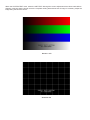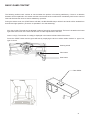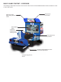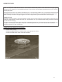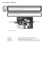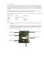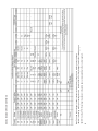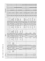
1
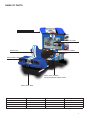
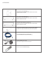
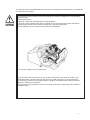
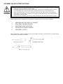
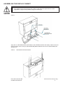
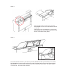
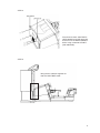
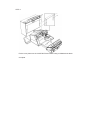
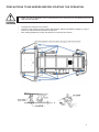
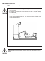
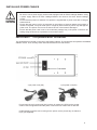
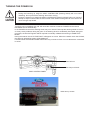
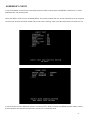
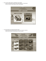
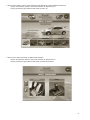
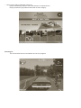
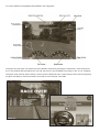
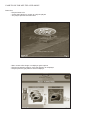
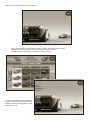
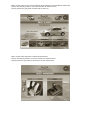
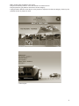
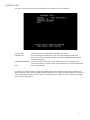
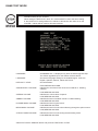
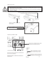
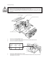
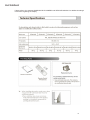
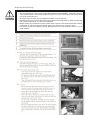
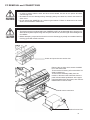
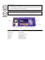
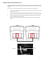
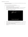
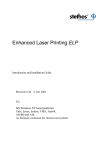
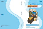
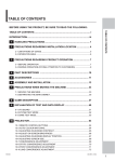
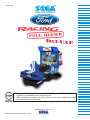
1st Printing
OPERATIONS MANUAL
•
•
Before using this product, read this OWNER’S and SERVICE MANUAL
carefully to understand the contents herein.
After reading this manual, be sure to keep it safe and nearby the product
for reference when necessary.
Manufactured in the UK by
Manual Part Number. 420-0001-01UK
BEFORE USING THIS PRODUCT (Be sure to read the following)
To ensure the safe usage of this product, be sure to read the following before use. The following
instructions are intended for the users, operators and the personnel in charge of the operation of the
product. After carefully reading and sufficiently understanding the warning displays and cautions,
handle the product appropriately. Be sure to keep this manual nearby the product or elsewhere convenient for referring to it when necessary.
Herein, explanations which require special attention are enclosed with dual lines. Depending on the
potentially hazardous degree, the term of STOP!, WARNING!, CAUTION!, etc. are used. Be sure to
understand the contents of these displays before reading the text.
Indicates that mishandling the product by disregarding this caution will
cause a slight hazardous situation
which can result in personal injury
and or material damage.
Indicates that mishandling the product by disregarding this warning will
cause a potentially hazardous situation which can result in death or
serious injury.
Indicates that mishandling the product by disregarding this symbol can cause the
products intrinsic performance not to be obtained, resulting in malfunction.
For the safe usage of the product, the following pictographs are used:
Indicates “HANDLE WITH CARE”. In order to protect the human body and equipment,
this label is attached to place within the product where this manual should be referred
to.
Indicates a “Protective Earth Terminal”. Before operating the equipment, be sure to correctly connect it to an Earth point.
Perform work in accordance with the instructions herein stated.
Instructions for work are explained by paying attention to the aspect of accident prevention. Failing
to perform work as per the instructions can cause accidents. In cases where only those who have
technical expertise should perform the work to avoid hazardous situations, the instructions herein
state that the serviceman should perform such work.
Be sure to turn off power before working the machine.
To prevent electric shock, be sure to turn off the power before starting the work in which the worker
touches the interior of the product. If the work is to be performed in the power-on status, this manual
herein always states to that effect.
Ensure that the Power Supply used is equipped with an Earth Leakage Breaker.
This product does not incorporate an earth leakage breaker. Using a power supply which is not
equipped with an Earth Leakage can cause a fire when earth leakage occurs.
Be sure to use fuses which meet the specified rating.
Using fuses exceeding the specified rating can cause a fire and electric shock.
Specification changes (removal of equipment, conversion and addition) not designed by
SEGA are not allowed.
The parts of the product include warning labels for safety, covers for personal protection, etc. It
is very hazardous to operate the product by removing parts and or modifying the circuits. Should
doors, lids and protective parts be damaged or lost, refrain from operating the product, and contact
where the product was purchased or the office stated herein.
Ensure that the product meets the requirements of appropriate Electrical Specifications.
Before installing the product, check for Electrical Specifications. SEGA products have a nameplate
on which Electrical Specifications are described. Ensure that the product is compatible with the
power supply voltage and frequency requirements of the location. Using any Electrical Specifications can cause a fire and electrical shock.
Install and operate the product in places where appropriate lighting is available, allowing
warning labels to be clearly read.
To ensure safety for the customers, ;labels and printed instructions describing potentially hazardous
situations are applied to places where accidents may be caused. Ensure that where the product is
operated has sufficient lighting to allow the warning labels to be read. If any labels are peeled off or
defaced, re-apply or replace them immediately. Please place an order with where the product was
purchased or the office stated herein.
When handling the CRT / Monitor, be very careful. (Applies only to products using CRT).
Some of the CRT / Monitor (TV) parts are subject to high tension voltage. Even after turning off
power to the product, some portions are still subject to the high tension voltage. Monitor repair or
replacement should only be performed by those with electrical knowledge and technical expertise.
When transporting or re selling this product, be sure to attach this manual to the product.
Descriptions herein contained may be subject to improvement changes without notice.
The contents described herein are fully prepared with due care. However, should any questions
arise or errors be found, please contact SEGA.
INSPECTION IMMEDIATELY AFTER TRANSPORTING THE PRODUCT TO THE LOCATION.
Normally at the time of shipment, SEGA products are in a status allowing for usage immediately
after transportation to the location. Nevertheless, an irregular situation may occur during transportation. Before turning on the power, check the following points to ensure that the product has been
transported in a satisfactory status.
•
•
•
•
•
•
•
•
Are there any dented portions or defects (cuts, etc.) on the external surfaces of the cabinet?
Are the castors or height adjuster damaged?
Do the power supply voltage and frequency requirements meet those of the location?
Are all wiring connectors correctly secured?
Are any of the power cords damaged?
Do the fuses used meet the specific rating?
Are all the accessories available?
Can all doors and lids be opened and closed securely?
Table of Contents
SPECIFICATIONS
DEFINITION OF SERVICE ENGINEER AND MAINTENANCE MAN
CONCERNING THE STICKER DISPLAY
CONCERNING WARNING DISPLAY
HANDLING PRECAUTIONS
PRECAUTIONS CONCERNING INSTALLATION
INSTALLATION SPACE REQUIRED
NAME OF PARTS
ACCESSORIES
PAYING ATTENTION TO CUSTOMERS
PRECAUTIONS TO BE HEEDED (BY CUSTOMERS) DURING THE OPERATION
ASSEMBLING WITH PRECAUTIONS
ASSEMBLING THE DISPLAY CABINET
PRECAUTIONS TO BE HEEDED BEFORE STARTING THE OPERATION
SECURING INTO PLACE
INSTALLING POWER CABLES
TURNING THE POWER ON
BASIC GAME CONTENT
BASIC GAME CONTENT - OVERVIEW
HOW TO PLAY
TEST MODE
GAME TEST MODE
MAINTENANCE
DLP DISPLAY
PC REMOVAL and CONNECTIONS
CONNECTIONS FOR NETWORK PLAY
COIN TOWER - OPERATION
DESIGN RELATED PARTS
1
2
3
3
4
5
6
7
8
9
10
12
13
17
18
19
20
23
24
25
37
52
53
61
63
65
67
72
SPECIFICATIONS
Installation space:
2000mm (W) X 3000mm (D)
Height:
2200mm
Weight:
400kg.
Power, Max current:
2.2A. (AC 230V 50Hz)
Display type:
Samsung 50” DLP
INTRODUCTION TO THIS MANUAL
This Owners’ and Service Manual is intended to provide detailed descriptions together with all the
necessary information covering the general operation of electronic assemblies, electromechanical,
servicing control, spare parts, etc. as regards the product, FORD RACING DELUXE
This manual is intended for the owners, personnel and managers in charge of operation of this product.
Operate the product after carefully reading and sufficiently understanding the instructions herein. If the
product fails to function satisfactorily, under no circumstances should a non technical person touch the
internal parts of the machine. Please contact the office where the product was purchased for any enquiries.
sega AMUSEMENTS EUROPE LIMITED
Suite 3a, Oaks House,
12 - 22 West Street
Epsom,
SURREY.
UNITED KINGDOM
KT18 7RG
1
DEFINITION OF SERVICE ENGINEER AND MAINTENANCE MAN
Non-technical personnel who do not have technical knowledge and expertise should refrain
from performing such technical work that is detailed in this manual. Only QUALIFIED SERVICE
ENGINEERS should perform work either inside or outside the compass of this manual. Failing to
comply with this instruction may cause a severe accident, electric shock or even death.
Ensure that parts replacement, servicing & inspections and troubleshooting are carried out by the location’s maintenance man. It is instructed herein that particularly hazardous work should be performed by
Qualified Service Engineers or Electrical / Mechanical Engineers who have expertise within this field.
The location’s Maintenance man and Qualified Service Engineers are defined as follows:
“Location’s Maintenance Man”
Those who have been trained or have experience in the maintenance of amusement machines and or
vending equipment, and also participates in the servicing and control of the equipment through such
routine work as equipment assembly, servicing and inspections and replacement of consumable, etc.
within the Amusement Facilities and or locations under management of the owner or operators of the
product.
Activities of the Location’s Maintenance Man:
Assembly & installation, servicing & inspections and replacement of units and consumable as regards
amusement equipment and vending machines, etc.
“Qualified Service Engineer”:
Those who or who have participated and/or qualified in the design, manufacture or inspection of amusement equipment at an amusement equipment manufacture or those who have been trained and certified within the field by operational companies.
Those who have technical expertise equivalent to that of a technical high school graduate as regards to
electricity, electronics and or mechanical engineering and daily take part in servicing, control and repair
of amusement equipment.
Qualified Service Engineer’s activities:
Assembly & installation and repair & adjustment of electrical, electronic and mechanical parts of amusement equipment and vending machines.
CONCERNING THE STICKER DISPLAY
SEGA products has stickers describing the product
manufacture No. (Serial No.) and Electrical
Specifications. Also it has a sticker describing where to
contact for repair and for purchasing parts.
When inquiring about or asking for repair, mention the
Serial No. and Name of Machine indicated on the sticker.
The Serial No. Indicates the product register. Identical
machines could have different parts fitted depending
on the date of manufacture. Also, improvements
and modifications might have been made after the
publication of this manual. In order to meet the above
situations, mention the Serial No. when contacting the
applicable places.
CONCERNING WARNING DISPLAY
SEGA products have warning displays on stickers,
Labels and or printed instructions adhered / attached
to or incorporated in the places where a potentially
hazardous situation can arise. The warning displays are
intended for accident prevention for the customer and for
avoiding hazardous situations relating to maintenance
and service work. There are some portions in the
cabinet, which are subject to height tension voltage, etc.
where accidents can be caused merely by touching.
When performing the servicing work, be careful of
the warning displays. Especially, any complex repair
and replacement work not mentioned herein, should
be performed by those technical personnel who have
knowledge of electrical and technical expertise.
For the prevention of accidents, caution any customer
whose acts run counter to the warnings, as to the effect
that he must stop that act.
3
HANDLING PRECAUTIONS
When installing or inspecting the machine, be very careful of the following points and pay attention to
ensure that the player can enjoy the game safely.
Non-compliance with the following points or inappropriate handling running counter to the cautionary
matters herein stated can cause personal injury or damage to the equipment.
•
•
•
•
•
•
•
•
•
•
•
•
•
•
•
Before performing the work, be sure to turn the power off. Performing work without turning the
power off can cause electric shock or a short circuit condition. In the cases where work should
be carried out when the equipment is powered on, this manual will always state to that effect.
To avoid electric shock or short circuit, do not plug in or unplug quickly.
To avoid electrical shock, do not plug in or unplug with wet hands or within a wet environment.
Do not expose Power Cords or Earth wires on the surface, (floor, etc.). If exposed, the power
cord and or Earth wires may be susceptible to damage. Damage cords or wires may cause and
electric shock or short circuit.
To avoid causing electric shock or fires, do not rest or put objects upon the power cords.
During or after installing the product, do not unnecessarily pull the power cord. If damaged the
power cord can cause electric shock, fire or a short circuit hazard.
In case the power cord is damaged, ask for a replacement through where the product was
purchased or from the office stated herein. Using a damaged or faulty power cord may cause
electric shock, fire or a short circuit condition.
Be sure to earth the product correctly. Inappropriate earthing may cause electric shock or fire
hazard.
Be sure to use fuses that meet the specified rating for the product. Using fuses exceeding the
specified rating may cause electric shock and or fire hazard.
Be sure all connectors are firmly made. Connectors that are not completely made can cause a
fire hazard.
To avoid causing electric shock, short circuit or fire hazards, do not make specification changes
by removing, converting or by making any additions to the product unless otherwise designated
by SEGA.
Be sure to perform periodic maintenance inspections herein stated.
For IC board inspections only use a logic analyser / tester. The use of a multi-purpose tester is
not permitted.
When cleaning the CRT or display surface, use a dry soft cloth. DO not apply chemicals such
as thinner, benzine, etc.
The electronic parts of the IC board can be damaged due to static electricity carried by the human body. Before performing any IC board related work, be sure to discharge any physically
accumulated static by touching a grounded metallic surface or by attaching an earth strap.
PRECAUTIONS CONCERNING INSTALLATION
This product is an indoor game machine. Do not install it outside. Even indoors, avoid installing in
places mentioned below so as not to cause a fire, electric shock, injury or malfunction.
•
•
•
•
•
•
•
•
•
Places subject to rain or water leakage, or places subject to high temperatures in the proximity
of an indoor swimming pool and or shower etc.
Places subject to direct sunlight or places subject to high temperatures in the proximity of heating units, etc.
Places filled with inflammable gas or vicinity of highly inflammable/volatile chemicals or hazardous matter.
Dust places.
Sloped surfaces.
Places subject to any type of violent impact.
Vicinity of anti-disaster facilities such as fire exits and fire extinguishers.
The opening (ambient) temperature range is from 5 to 40 degrees centigrade. Only in cases
where a projector is employed, the temperature range is 5 to 30 degrees centigrade.
This product is not suitable to be installed into an area where a Power or Jet wash can be
used.
LIMITATIONS OF USAGE REQUIREMENTS
•
•
•
•
•
•
•
Be sure to check the Electrical Specifications.
Ensure that this product is compatible with the location’s power supply, voltage and frequency
requirements. A plate describing the Electrical Specifications is attached to the product. Noncompliance with the Electrical Specifications can cause a fire and/or electric shock.
This product requires a Circuit Breaker as part of the location facilities. Using them independent
from the product can cause electric shock and or fire hazard.
Ensure that the indoor rating for the power supply is rated at 7A or higher. Non-compliance with
the Electrical Specifications can cause electric shock or fire hazard.
Be sure to independently use a power supply equipped with an Earth Leakage Breaker. Using a
power supply without and Earth Leakage Breaker may cause an electric shock or fire hazard.
Applying too many loads to a single feed can cause a generation of heat and result in a fire
hazard resulting from an overload.
When using an extension cord, ensure that the cord is rated at 7A or higher. Using a cord rated
lower than specified may cause a fire hazard or electric shock.
5
INSTALLATION SPACE REQUIRED
•
•
Note that for transporting the machine into location, the minimum clearance required for a doorway or entrance is 1.5 m (W) and 1.5 m (D).
For the operation of this machine, secure a minimum area of 2.0 m (W) X 3.0 m (D). For ventilation, provide an approximate space of 20cm between the rear of the cabinet and the wall.
200mm
700mm
NAME OF PARTS
ASSY BILLBOARD
ASSY DISPLAY CABI
ASSY CONTROL PANEL
ASSY SEAT
ASSY MAIN CABI
ASSY COIN TOWER
INCORPORATING GEAR SHIFT
ASSY BASE BOX
Description
Width
Depth
Height
ASSY BILLBOARD
131CM
47CM
35CM
ASSY DISPLAY CABI
150CM
65CM
154CM
ASSY MAIN CABI
112CM
220CM
99CM
ASSEMBLED
150CM
267CM
190CM
7
ACCESSORIES
ORP-0001UK JOINT BRACKET X 1.
Secures to the front of the ASSY MAIN CABI so that the ASSY
DISPLAY CABI can be fixed.
ORP-0002UK JOINT BRACKET X 1.
Secures to the front of the ASSY MAIN CABI so that the ASSY
DISPLAY CABI can be fixed.
NCR-0002 JOINT BRACKET CENTRE X 2.
Secures to the front of the ASSY MAIN CABI so that the ASSY
DISPLAY CABI can be fixed.
Fixings which enable the installer to fit and fix the two cabinets
together and to apply the billboard into place before operation.
600-7269-0500UK ASSY LAN CABLE 0500
To connect between two cabinets for linked play
LM1227 MAINS LEAD 10A UK
Mains lead to supply the machine with power
Remote control for SAMSUNG display.
PAYING ATTENTION TO CUSTOMERS
To avoid injury and unacceptable behaviour be sure to constantly give careful attention to the players
and observers of the game.
•
•
•
•
To avoid electric shock and short circuit, do not allow customers to put hand or fingers or any
extraneous matter in any of the openings around the product.
To avoid customer injury due to tripping or falling, immediately stop customers from leaning on
or climbing on the product.
To avoid electric shock and short circuit, do not allow customers to unplug the power cord without a justifiable reason.
To avoid injury resulting from items falling of the machine, instruct the player(s) not to place any
items, included drinks on the machine.
Immediately stop such violent acts as hitting of kicking the product. Such violent acts can cause
parts damage and or injury to the player and/or potential players.
9
PRECAUTIONS TO BE HEEDED (BY CUSTOMERS) DURING THE OPERATION
To avoid injury and unacceptable behaviour be sure to constantly give careful attention to the players
and observers of the game.
•
•
•
•
To avoid electric shock and short circuit, do not allow customers to put hand or fingers or any
extraneous matter in any of the openings around the product.
To avoid customer injury due to tripping or falling, immediately stop customers from leaning on
or climbing on the product.
To avoid electric shock and short circuit, do not allow customers to unplug the power cord without a justifiable reason.
To avoid injury resulting from items falling of the machine, instruct the player(s) not to place any
items, included drinks on the machine.
Immediately stop such violent acts as hitting of kicking the product. Such violent acts can cause
parts damage and or injury to the player and/or potential players.
To avoid injury and unacceptable behaviour be sure to constantly give careful attention to the players
and observers of the game.
To avoid injury and accidents, those who fall under the following categories are not allowed to
play the game.
Intoxicated persons.
Those who have high blood pressure or heart problems.
Those who have experienced muscle convulsion or loss of consciousness when exposed to
intensive light stimulus due to watching television or playing video games.
Persons whose act runs counter to the products warning labels.
Do not place drinks on the on the product
To avoid electric shock or short circuit, do not allow customers to put hands or fingers or any
extraneous matter into the opening of the product or small openings in or around the doors.
To avoid injury resulting from customer falling or tripping, immediately stop customers leaning
against or climbing on the product.
To avoid electric shock and short circuit, do not allow customers to unplug the power without a
justifiable reason.
11
ASSEMBLING WITH PRECAUTIONS
•
•
•
•
Perform assembly work by following the procedure herein stated. Failing to comply with the
instructions can cause electric shock hazard.
Assembly should be performed as per this manual. Since this is a complex machine, erroneous assembling may cause electric shock, machine damage and or poor performance.
When assembling, be sure to use a minimum of two persons. Depending on the assembly
work, there are some cases in which by one person working alone may cause personal injury
or damage to machine parts.
Ensure that all connectors are correctly made. Incomplete connections can cause a hazard.
When carrying out the assembly work, follow the procedure below in the correct sequence.
1.
2.
3.
4.
5.
ASSEMBLING THE DISPLAY CABINET
SECURING THE BILLBOARD
SECURING INTO LOCATION
INSTALLING POWER CABLES
ASSEMBLY CHECK
When assembling, make sure that tools such as a Phillips screwdriver, an M4 wrench or socket and an
M16 Wrench or socket are available.
ASSEMBLING THE DISPLAY CABINET
•
Only tighten fixings when all fixings are in place. If the fixings are tightened as the work
progresses, it might not be possible to align the final fixings.
STEP 1
Apply the 2x JOINT BRACKETS (NCR-0002) to the CENTRE PLATE of the display cabinet as shown.
Once in position secure using 4x (030-000830-SB) M8x30 HEX BLT BLK and 4x (060-F00800) M8
WSHR FLAT.
STEP 2
SECURING THE BILLBOARD
Place the ASSY BILLBOARD on to the DISPLAY CABINET as shown and secure from the top using
6x M6x20 HEX BOLTS
13
STEP 3
Make the electrical connection from the ASSY
BILLBOARD in to the roof of the DISPLAY cabinet
on the LHS.
Place both covers (FD-0505UK) on to the ASSY
BILLBOARD and secure using 8x 000-T00412-0B
M4x12 Truss head screws (black).
STEP 4
Fit the BILLBOARD PLATE L (FD-0501UK) and BILLBOARD PLATE R (FD-0502UK) to the ASSY
BILLBOARD as shown and secure using 10x (000-T00412-0B) M4x12 Truss head screws (black).
IMPORTANT - DO NOT USE POWER TOOLS TO SECURE THIS PART. DO NOT OVER
TIGHTEN AS THE PART MAY CRACK.
STEP 5
Fit and secure both JOINT BKTS
(ORP-0002UK and ORP-0001UK)
to the front of the MAIN CABINET
ASSY using 4x M8x30 HEX BLT
(030-00830-SB).
STEP 6
Bring the two cabinets together so
that the JOINT BKTs meet.
15
STEP 7
Fit the cover plate over the JOINT BKTS and secure using 4x M8X30 bolts black.
Complete.
PRECAUTIONS TO BE HEEDED BEFORE STARTING THE OPERATION
•
Make sure that all adjusters are in contact with the floor. If they are not, the cabinet may move
and cause an accident.
•
•
Transport the machine to its location.
Have all of the adjusters make contact with the floor. Adjust the adjuster’s height by using a
wrench so that the machine position is kept level.
After making adjustment, fasten the adjuster nut upwards and secure.
•
17
SECURING INTO PLACE
To avoid injury, be sure to constantly give careful attention to the behaviour and manner of visitors and
players.
In order to avoid accidents, check the following before starting the operation of the machine.
• Check if all the adjusters are in contact with the floor. If they are not, the cabinet may move and
cause an accident.
• Do not put any heavy items on this product. Placing any heavy item on the product can cause
an accident if it falls
• Do not climb on the product. Climbing on the product can cause an accident if anyone falls. To
check the top portion of the cabinet, use a set of step ladders.
• To avoid electric shock, check all doors are secure and all protective covers in place.
• To avoid the risk of electric shock, short circuit or damage, do not put the following items on
or in the vicinity of the product: Flower vase, cups, water tanks, cosmetics and or any vessels
containing water or chemicals.
To avoid injury, be sure to provide sufficient space considering the potential crowded situation at the
installation location. Insufficient installation space may result in injury due to contact by a player or
observer.
INSTALLING POWER CABLES
•
•
•
•
Be sure to use a power supply socket outlet equipped with an Earth Leakage Breaker. Using
a power supply without an Earth Leakage Breaker can cause a fire when electric leakage
occurs.
Ensure that this product is earthed. This product is supplied with a power cord with an integral
earth terminal.
Ensure that the power cord is not exposed on the surface of the area where the machine is
located. If exposed, it may be stood upon or caught by other machinery which may damage the
power cord. The power cord can be an electric shock or fire hazard if damaged.
Ensure that the power cord is not in the customers passage way, if the power cord has to be
trailing along the floor then a protective cover must be used.
IMPORTANT!
This product MUST be earthed
The AC Bracket is mounted on the rear of the Display Cabinet. The AC Bracket incorporates the MAINS
ON/OFF switch, Fuse, Primary Earth Terminal and the IEC AC Inlet socket.
3 pin power cord (UK)
2 pin power cord (EU)
Firmly insert the 3 pin power plug (UK) or the 2 pin power plug (EU) into the socket
outlet. Insert the opposite end of the power cord into the AC inlet of the AC bracket.
Install suitable protective wire covering for the power cord to prevent any accidents or
injury (not supplied).
19
TURNING THE POWER ON
•
•
During the Powering up stage the ASSY CONTROLLER (Steering Wheel) will move while
initialising. Do not prevent the steering wheel from moving.
During the Powering up stages the ASSY CONTROLLER (Steering Wheel) will move. DO NOT
attempt to adjust or work under the bonnet area of the cabinet as the gears will move which can
cause a finger trap hazard.
Turning the AC unit MAINS SW “ON” will cause the machine to start the POWER ON check and
NETWORK check automatically.
In the POWER ON check the steering wheel may turn. DO NOT interrupt the steering wheel as it turns
as it may cause problems during the game. If the steering wheel is accidentally interrupted during this
procedure, the Service Engineer will be required to manually calibrate the steering in GAME TEST
MODE.
During the network check “PLEASE WAIT” will appear on screen. When the network check has finished,
the attract or advertising screen will be displayed.
PLEASE NOTE that the NETWORK CHECK will only commence if two or more cabinets are connected
in series.
Steering Wheel will turn
Start and View lamps will be lit
ASSY CONTROL PANEL
Initial start up screen
ASSEMBLEY CHECK
In the TEST MODE, ensure that the assembly has been made correctly and the GAME BD is satisfactory. In TEST
MODE perform the following tests.
Select the INPUT TEST from the SYSTEM MENU. This screen enables the user to test individual inputs to the game.
Once all input devices have been tested and proven to be in working order, press the test and service buttons to exit.
In the sound test, use the SERVICE switch to access the LEFT, RIGHT, FRONT and REAR speaker outputs. Check
that all speakers are operational and that the sound is at a comfortable level.
21
Within the SYSTEM TEST menu, select the CRT TEST. Although the screen adjustments have been made before
shipping, make sur that the image covers the complete veiwing area without loss of image. If necessary, adjust the
image using the Remote control.
Screen 1 of 2
Screen 2 of 2
BASIC GAME CONTENT
The following outlines basic routines to check whether the product is functioning satisfactory. If there is a deviation
between what is explained in this section and the actual results of the machine then immediately look into the cause of
fault and eliminate the cause to ensure satisfactory operation.
During the attract mode, the START button will flash, the BILLBOARD lamps will be lit and audio will be emitted from
both left and right speakers. (There are no speakers in the seat assembly).
Sit in the Cockpit. The seat can be adjusted in either a forward or reverse positions. The lever is located on the lower
right hand side in front of the seat. Pull this lever to make adjustments to the seat.
Insert a coin(s). The number of credit(s) is displayed in the bottom left hand side of the screen.
Press the “START” button and the game will start by employing the driver to select certain criteria’s i.e. type of car,
type of course.
Steering wheel
View button
Start button
Gear Shifter
23
BASIC GAME CONTENT - OVERVIEW
The following outlines basic functions of the machine. Each function will be established either within the attraction mode
or from within game.
Title panel is
illuminated.
Sequence LEDs
flash during attraction
mode.
DLP displays
game.
Interactive
feedback from
steering wheel.
Audio output from
5 speakers.
Sequence LEDs within the brake
and reverse lights flash.
Concept image shown
above.
HOW TO PLAY
BASIC CONTROLS
Insert coin and press credit transfer button to move credit to desired seat position. Press Start button to begin a game.
Choose your car category, car, transmission and track. View choices with the steering wheel and enter your selection
with the gas pedal.
During game play use the gas pedal to accelerate your car and the brake pedal to stop. In automatic transmission the
brake pedal also cause the car to reverse if pressed when the car is stationary. In manual transmission use the gear
shifter to shift up and down through the gears. The view change button cycles between three camera angles.
GAME OUTLINE
The player controls a Ford car and races against six other cars to achieve a lap time record before the time limit is up.
There is a great selection of tracks and cars. The off-road tracks can only be selected when a player selects a vehicle
from the off-road category.
The race consists of three laps and the time limit is extended after each lap. If the time limit runs out the game is over.
The game can be played alone against computer-controlled opponents or up to 3 twin cabinets can be linked for
multiplayer games of up to 6 challengers
GAME FLOW FOR SINGLE PLAYER MODE
•
•
•
Player inserts coin(s)
Press the CREDIT button to transfer credits to the appropriate cabinet.
Press the START button when credits are available.
25
•
Menu screen offers single or multiplayer game option
Player uses steering wheel to move the selection to single player
Player presses the gas pedal to select single player
•
The next option is to choose the vehicle class.
Player uses the steering wheel to move to the selection required
Player then presses the gas pedal to select to option.
•
Menu screen offers 6 cars in three difficulty levels (Beginner, Intermediate & Advanced)
Player uses steering wheel to move the selection to desired choice
Player presses the gas pedal to select their chosen car
•
Menu screen offers Automatic or Manual transmission
Player uses steering wheel to move the selection to desired choice
Player presses the gas pedal to select their chosen transmission
27
•
Menu screen offers a selection of 6 tracks
Player uses steering wheel to move the selection to desired choice
Player presses the gas pedal to select their chosen category
Race begins
The screen below shows a screenshot of a race in progress.
On screen displays are highlighted and labelled in the image blow.
During the race the player can select from three different viewpoint by pressing the view button. These view points
are: In Car, behind close and behind far. The rear view mirror is only available to the player in the “In Car” viewpoint.
The player must use their skill to finish the race in the time allotted to them. If their total race time is fast enough they
are given the ability to enter three initials next to their score in the high score table.
29
GAME FLOW FOR MULTIPLAYER MODE
Game flow:
• Players inserts coin
• “Press Start” flashes on screen to notify the players
• The players presses the start button
• Menu screen offers single or multiplayer game options
• Players use steering wheel to move the selection to multiplayer
• Players press the gas pedal to select multiplayer
Players wait for other players to join the game
• Menu screen offers car categories of classic, modern, performance and off-road
• Players use steering wheel to move the selection to desired choice
• Players press the gas pedal to select their chosen category
If players select different categories then
a voting system is employed so that the
category chosen by the greatest number
of players is used
31
• Menu screen offers 6 cars in three difficulty levels (Beginner, Intermediate & Advanced)
• Player uses steering wheel to move the selection to desired choice
• Player presses the gas pedal to select their chosen car
• Menu screen offers Automatic or Manual transmission
• Player use steering wheel to move the selection to desired choice
• Players press the gas pedal to select their chosen transmission
• Menu screen offers a selection of 6 tracks.
• Players use steering wheel to move the selection to desired choice.
• Players press the gas pedal to select their chosen category.
• If players select different tracks then a voting system is employed so that the category chosen by the
greatest number of players is used.
• Race begins
33
TECHNIQUES AND SECRETS
Super Start
If a player keeps the Revs of their car between 5,000 and 6,000 when the race begins they are given a speed boost.
Hidden Shortcuts
Some of the tracks have hidden shortcuts that can help reduce lap times.
Cars
The table below details all the cars available. Please note that only the cars for your given region (US or European)
will be available. The Update column details the cars that will be swapped out with the vehicles marked with a * on the
preset update day.
1
2
3
4
5
6
Start up
Europe
1970 Mk1 Capri RS2600 1
‘‘76 Gran Torino
2
‘68 Mustang GT
3
‘71 Mustang Mach 1
4
‘66 Fairlane GT*
5
‘64 Galaxie 500*
6
US
1972 Ranchero GT
‘71 Mustang Mach 1
‘76 Gran Torino
‘66 Fairlane GT
‘64 Galaxie 500*
66 Thunderbird
Convertible*
Update
1
2
‘55 Thunderbird
1972 Ranchero GT
Modern
1
2
3
4
Europe
1978 Mk III Capri 3.0S
SVT Focus
SVT Cobra
2004 Mondeo ST220
5
6
1999 Racing Puma*
2004 SVT Lightning*
Start up
1
2
3
4
5
6
US
Crown Victoria*
SVT Focus
SVT Cobra
Update
1
2
Fortynine Concept
SVT Lightning
2003 Limited Edition
Thunderbird
Powerstroke Concept
2004 SVT Lightning*
Performance
1
2
3
4
5
6
Europe
Focus FR200*
1992 Escort RS
Ford GT
2005 Mustang GT
1987 Sierra RS500
FR100 Concept*
Start up
1
2
3
4
5
6
US
Focus FR200
Indigo Concept
Ford GT
2005 Mustang GT
Mustang FR500*
FR100 Concept*
Update
1
2
Mustang GT-R
GT90 Concept
Off road
1
2
3
4
5
6
Europe
1999 Focus Rally Car
1973 Escort RS2000
1985 RS200
F-350 XLT Sport
Ex Concept*
2004 F-150 FX4*
Start up
1
2
3
4
5
6
US
Ex Concept
2004 F-150 FX4
F-350 XLT Sport
F-150 4x4 Flareside
‘65 F-100*
‘56 F-100*
Update
1
2
48 F1
Explorer Sport Trac XLT
The tables below detail the tracks available to select initially and after the preset update day.
Initial Tracks
1
2
3
Road Tracks
Harbour – Forward
Railroad – Reverse
Quaker Town – Forward
1
2
3
Off Road Tracks
White Sands - Reverse
Voodoo Village - Forward
Colonial Grounds - Reverse
1
2
3
Mountain Village - Forward
Summit Trials - Reverse
Race Track
1
2
3
Fishing Town - Forward
Logging Company - Reverse
Oil Refinery – Forward
Update Tracks
1
2
3
Road Tracks
Harbour – Reverse
Quaker Town – Reverse
Race Track
1
2
3
Off Road Tracks
White Sands - Forward
Voodoo Village - Reverse
Colonial Grounds – Forward
1
2
3
City Highway - Forward
Mountain Village - Reverse
Summit Trials - Forward
1
2
3
Fishing Town - Reverse
Logging Company - Forward
Oil Refinery - Reverse
NOTE: The updated tracks become available only when the AUTO UPDATE has taken place.
Please see the next section in this manual regarding the UPGRADE of software.
35
UPGRADES
This product comes with an AUTOMATIC upgrade in software.
On the 1st March 2007 the machine will perform an AUTOMATIC UPGRADE and the software will be updated to give
the player a number of NEW racing track and NEW cars.
28 days prior the OFFICIAL software drop, players will be advised that an UPGRADE will take place.
The machine will display a 28 DAY counter during the attract mode.
•
Only QUALIFIED SERVICE PERSONNEL should carry out updates in software.
Once the UPGRADE has taken place the operator is able to access the GAME TEST MODE and chooses to enable
either UPGRADE or STANDARD version by turning the UPGRADES ON/OFF.
GAME TEST SCREEN BEFORE UPGRADE
GAME TEST SCREEN AFTER UPGRADE
TEST MODE
• When changes are made in the TEST MODES, be sure to EXIT from each TEST MENU in turn
before returning to GAME MODE. If power is removed whilst the machine is in TEST MODE,
any changes made will not take effect.
The Test Menu allows the functioning of each part of the cabinet to be checked, the monitor to be
adjusted and the coins and various related game setting to be changed.
•
•
•
Press the test button to enable the TEST MODE to be displayed on screen.
Press the SERVICE BUTTON to move the pointer on-screen to the desired function.
Once the desired function has been established, press the TEST BUTTON to enter.
SYSTEM INFORMATION
UGCI TEST
INPUT TEST
CALIBRATE TEST
OUTPUT TEST
COIN TEST
SOUND TEST
CRT TEST
DRIVE BOARD TEST
BOOKKEEPING
CLOCK SETTING
NETWORK TEST
Displays general information on installed software and hardware.
Displays test routines for UGCI communications.
Displays test routines for input devices.
Displays calibration test for input devices.
Displays test routines for output devices.
Displays test routine for coin handling devices.
Displays test routine for audio outputs.
Displays test routine for visual adjustment.
Displays test routines for steering force feedback system.
Displays pages of various game information.
Displays the setting for the internal clock.
Displays test routine for communications.
The operator uses the SERVICE button to select the desired test routines and presses the TEST button
to activate choice.
37
SYSTEM INFORMATION
This test displays general system information regarding the hardware configuration and installed
software.
SYSTEM ID
DISK IMAGE
LAUNCHER VERSION GAME SHELL VERSION
GAME NAME GAME VERSION UGCI VERSION IBUTTON EXIT A unique 64 bit ID code to identify the system
Version number for master disk image
Version number for System Launcher
Version number for Game Shell
Name of the installed game
Version number of installed game
Hardware version of installed UGCI board
Type of iButton installed (Game Name or SYSTEM). If no iButton is
installed, then a NOT FOUND message is shown
Return to SYSTEM MENU
The user cannot modify any of the parameters in this test. The user must press the TEST button to exit
this test.
UGCI TEST
This test is used to test the network link between the computer and the UGCI board.
COIN 1 COUNT
COIN 2 COUNT
VERSION UGCI STATUS EXIT Value of UGCI NVR coin count 1
Value of UGCI NVR coin count 2
Version number of UGCI board
OK is the system can communicate with the UGCI board, otherwise a NOT
CONNECTED message is shown.
Return to SYSTEM MENU
The user cannot modify any of the parameters in this test. The user must press the TEST button to exit
this test.
39
INPUT TEST
This test is used to test and calibrate the peripherals connected to the UGCI interface.
STEERING ACCELERATOR
BRAKE GEAR SHIFT START CHANGE VIEW
SERVICE TEST EXIT 00H = Full Left lock, 80H = Centre, FFH = Full right lock
00H = pedal fully up, FFH = pedal fully down
00H = pedal fully up, FFH = pedal fully down
UP = stick up, N = stick central, DOWN = stick down
On = pressed, OFF = not pressed
On = pressed, OFF = not pressed
On = pressed, OFF = not pressed
On = pressed, OFF = not pressed
Exit to System Menu
Please refer to the CALIBRATION TEST for calibrating the hand and foot controllers.
As this test will check for functionality of both the TEST and SERVICE buttons, in order to exit this test,
BOTH buttons must be pressed simultaneously.
CALIBRATION TEST
This test is used to calibrate the analogue system input devices, i.e. the steering wheel, throttle pedal
and brake pedal.
STEERING LEFT VAL STEERING LEFT VAL BRAKE DOWN VAL BRAKE UP VAL THROTTLE DOWN VAL
THROTTLE UP VAL CALIBRATE STEERING
CALIBRATE BRAKE CALIBRATE THROTTLE
EXIT The current maximum left position of the steering wheel
The current maximum right position of the steering wheel
The current maximum down position of the brake pedal
The current maximum up position of the brake pedal
The current maximum down position of the throttle pedal
The current maximum up position of the throttle pedal
Starts the steering calibration routine. The user must follow the on
screen prompts to turn the wheel full left and then full right
Starts the brake calibration routine The user must follow the on screen
prompts to fully depress and then release the brake pedal
Starts the throttle calibration routine. The user must follow the on
screen prompts to fully depress and then release the throttle pedal.
Exit to System Menu
The user will use the SERVICE button to select the desired test and the TEST button to activate the
test.
41
OUTPUT TEST
This test is used to test any output signals (i.e. lamps) from the system.
EXIT Exit to System Menu
There are currently no output tests defined. Use the TEST button to return to the System Menu.
COIN TEST
This test is used to set coin related parameters.:
COIN CHUTE This option is fixed to COMMON
COIN/CREDIT This is used to select how many credits per play are required. There are currently two options : 1 indicates 1 credit per play, and FREEPLAY indicates
that no credits are required for play. Note that the actual value of coins required
for 1 credit is defined by the VTS board settings.
EXIT Exit to System Menu
The user can select the LEFT and RIGHT speaker status to ON or OFF to test that speaker channel.
Use the TEST button to return to the System Menu.
43
SOUND TEST
This test is used to test the audio system is working correctly :
OUTPUT TYPE RIGHT SPEAKER LEFT SPEAKER EXIT This option is fixed to STEREO
When ON, a sound will be played from the RIGHT speaker
When ON, a sound will be played from the LEFT speaker
Exit to System Menu
The user can select the LEFT and RIGHT speaker status to ON or OFF to test that speaker channel.
Use the TEST button to return to the System Menu.
CRT TEST
This test is used to test the game display is working correctly. It consists of two screens :
COLOUR TEST
GRID TEST
Press the TEST button to move from COLOUR TEST to GRID TEST. Press the TEST button again to
return to the System Menu.
45
DRIVE BOARD TEST
This test is used to test the steering force feedback mechanism.
STOP MOTOR FULL LEFT FULL RIGHT MOTOR POWER
EXIT Turn off all drive signals to the force feedback motor
Apply a maximum left signal to the force feedback motor (subject to power
setting)
Apply a maximum right signal to the force feedback motor (subject to power
setting)
This has four settings :
NORMAL : A normal torque setting
STRONG : A strong torque setting (recommended for adult only environments)
WEAK : A very weak torque setting (recommended for child only environments)
NONE : No force feedback torque is applied.
Exit to System Menu
Once the user has selected the required motor power, he can test the setting by using the FULL LEFT
or FULL RIGHT test. All motor power will be removed when the user exits from the test.
BOOKKEEPING
This test is used to review statistical data from the system. It consists of 3 main screens of data.
Screen 1 contains an overview of game play data.
1PLYR GAMES PLAYED
MPLYR GAMES PLAYED
COIN CREDITS SERVICE CREDITS TOTAL TIME ON TOTAL 1PLYR TIME TOTAL MPLYR TIME AVERAGE 1PLYR TIME
AVERAGE MPLYR TIME
CLEAR HISCORES** CLEAR BOOKKEEPING
The total number of 1 player games played
The total number of multi player games played
The total number of coin credits entered
The total number of service credits entered
The total time the cabinet has been switched on, in HHHH:MM:SS
The total time of all 1 player games played, in HHHH:MM:SS
The total time of all multiplayer games played, in HHHH:MM:SS
The average game time for a 1 player game
The average game time for a multiplayer game
When selected, the user will be prompted to confirm, YES or NO. If the
user selects YES, the high-score table is reset to factory default. If NO
is selected, then no action is taken.
When selected, the user will be prompted to confirm, YES or NO. If
the user selects YES, all bookkeeping meters will be cleared to zero If
NO is selected, then no action is taken.
**When HISCORES are to be reset from the bookkeeping test menu, all linked cabinets must be
cleared. Put ALL linked cabinets into test mode and clear each of the HISCORES. Exit test and return to
game on each cabinet.
NEXT SCREEN Proceed to bookkeeping screen #2
47
Bookkeeping Screen 2 contains a breakdown of game plays on a day to day basis.
SUNDAY MONDAY TUESDAY WEDNESDAY THURSDAY FRIDAY SATURDAY NEXT SCREEN
The total number of games played on a Sunday
The total number of games played on a Monday
The total number of games played on a Tuesday
The total number of games played on a Wednesday
The total number of games played on a Thursday
The total number of games played on a Friday
The total number of games played on a Saturday
Proceed to bookkeeping screen #3
Bookkeeping Screen 3 contains a breakdown of game plays on a day to day basis.
00 - 01 01 - 02 23 - 00 EXIT The total number of games played between midnight and 1am
The total number of games played between 1am and 2am
The total number of games played between 11pm and midnight
To return to the SYSTEM TEST MENU SCREEN.
49
CLOCK SETTINGS
This test is used to set the current time and date of the computer system.
• Data cannot be changed until the AUTO UPDATE has been released. Once the AUTO UPDATE
has been released and installed, only then can data be changed.
YEAR MONTH DATE HOURS MINUTES SECONDS EXIT Variable from 2000 to 2050
Variable from 01 to 12
Variable from 1 to 28, 29, 30 or 31 (dependant on MONTH & YEAR)
Variable from 0 to 23
Variable from 0 to 59
Variable from 0 to 59
Exit to System Menu after adjusting clock to new value
NETWORK TEST
This test is used to test the network link between two computers in a twin cabinet.
STATUS OK CABINET ID CONFIRM CHANGES
EXIT if Ethernet link is operating, NOT AVAILABLE otherwise
ID of this cabinet, variable from 1 to 6. No linked cabinets should have the same ID. Once changed, the user must select CONFIRM CHANGES to
complete the setting.
The user will be prompted to confirm YES or NO. If YES is selected, the
system will perform a system reboot. If NO is selected, no action will be action.
Exit to System Menu
In order for the network status to display OK, BOTH sides of the cabinet must be set to network test.
When selected, the test will send data packets between the two systems to validate the link. If the link is
valid, the display will be shown OK. If the link is disconnected or otherwise not functioning, the display
will show NOT AVAILABLE.
51
GAME TEST MODE
•
•
•
All default setting shown in BOLD.
When setting the DIFFICULTY level, ALL cabinet MUST be set to the same setting.
IF the DIFFICULTY settings differ from cabinet to cabinet then the value set on the
PLAYER 1 cabinet will be used for all linked cabinets.
UPGRADES LANGUAGE DIFFICULTY LEVEL SOUND EFFECT VOLUME
SPEECH VOLUME AMBIENT VOLUME IN GAME MUSIC VOLUME
MENU MUSIC VOLUME
ATTRACT MODE VOLUME
UPGRADES ON – is displayed only after the official upgrade drop.
The official upgrade drop for this edition will be 01/03/07.
Choose the language setting for the installed region. Choice is:
English, Spanish, German, Italian and French.
Choose between:
EASY, MEDIUM and HARD.
Indicates the set volume level of the sound effects i.e. skidding, crashing.
LOW, MEDIUM and HIGH.
Indicates the volume level of speech.
LOW, MEDIUM and HIGH.
Indicates the level of ambient sounds i.e. Birds tweeting.
LOW, MEDIUM and HIGH.
Indicates the level of game music.
LOW, MEDIUM and HIGH.
Indicates the level of music when selecting through the option menus.
LOW, MEDIUM and HIGH.
Indicates the level of music during the advertising mode.
LOW, MEDIUM and HIGH.
Select EXIT with the SERVICE button and press the TEST button to EXIT.
MAINTENANCE
• This work should be carried out by QUALIFIED SERVICE PERSONNEL. Performing work by
a non qualified person can lead to an electric shock or a short circuit hazard which may result
in a fire or personnel injury.
• Be sure to remove power from the appliance before work commences.
• NEVER touch places or parts other that those specified. Touching places or parts not specified
may cause electric shock or a short circuit hazard.
• Before starting any maintenance work, ensure that the power is disconnected and the machine
is switched off. Failure to observe this precaution may cause injury or electric shock.
• Use care so as not to damage any wiring. Damaged wires can cause electric shock or a short
circuit hazard.
• For IC board inspections only use a logic analyser / tester. The use of a multi-purpose tester is
not permitted.
• When cleaning the CRT or display surface, use a dry soft cloth. DO not apply chemicals such
as thinners, benzine, etc.
• The electronic parts of the IC board can be damaged due to static electricity carried by the
human body. Before performing any IC board related work, be sure to discharge any physically
accumulated static by touching a grounded metallic surface or by attaching an earth strap.
53
Handle Mechanism
• Be sure to turn power off before performing work.
• Immediately after the game has finished, the motor may still be very hot after operation. When
performing any work when handling the motor, it may be necessary to wait until the motor has
cooled.
• The motor unit is HEAVY. Please take care when moving.
In the TEST MODE, if the steering wheel’s V.R. variations are not within the allowable range then replacement of
the V.R is needed. Also be sure to apply grease to the gears of the V.R mechanism once every 3 months to provide
optimum operation.
• After the replacement or adjustment of the handles V.R., be sure to set the correct values of the
V.R. using the CALIBRATION TEST in the TEST MENU.
Replacing or adjusting the handles V.R.
1. Turn off the power to the machine and disconnect from its supply.
2. Remove the connector from the V.R. harness.
3. Remove the screws which secure the V.R. bracket to the Mecca Assy.
4. Remove the V.R. Assy.
5. Reconstruct in reverse order.
6. After replacing the V.R., perform the adjustment in the CALIBRATION TEST.
1. Adjustment for the V.R is carried out in the CALIBRATION TEST.
2. Ensure that the steering wheel is in a central position before re-applying the V.R.
3. Enter TEST MODE and then CALIBRATION TEST.
(PLEASE REFER TO THE TEST MODE PAGES WITHIN THIS MANUAL FOR INSTRUCTION.)
Gear Shifter
•
•
•
•
Be sure to turn power off before performing work.
Failure to observe precautions may cause injury or electric shock.
Use care so as not to damage wiring. Damaged wires can cause electric shock or fire hazard.
Do not touch undesignated places. Touching places not specified can cause electric shock or
fire hazard.
If the SHIFT lever is not satisfactory, remove the SHIFT lever in the following procedure to replace the microswitch.
Gear Shifter
Tamper Proof Screws
M5x12. black
1.
Turn the power off and disconnect the machine from the electrical supply.
2.
Remove the 4 security screws located at
the top near the lever knob.
3.
Disconnect the harness and remove completely.
Each microswitch is secured using 2 machine screws. Remove the 2 screws and replace the microswitch using the illustration below.
1.
Disconnect the wiring connectors of the switch which is to be replaced.
2.
Remove the 2 self tap screws to remove
the microswitch.
GREASING
Apply grease once every 3 months to the
specified areas to ensure smooth operation
throughout the product life.
55
Accelerator & Brake
•
•
•
•
Be sure to turn power off before performing work.
Failure to observe precautions may cause injury or electric shock.
Use care so as not to damage wiring. Damaged wires can cause electric shock or fire hazard.
Do not touch undesignated places. Touching places not specified can cause electric shock or
fire hazard.
If the Accelerator and Brake operation is not satisfactory, adjustment of the volume installation position or V. R.
replacement is needed. Also, be sure to apply greasing to the gear portion once every 3 months.
Adjusting and replacing the V.R.
The appropriate value of each V.R. is 5K Ohms.
Since work is performed inside the energized cabinet, be careful so as not to touch undesignated portions. Touching
places not specified can cause electric shock or short circuit condition.
1.
Unscrew the 2 truss screws and remove
the front cover from the Accelerator and
Brake assembly.
2.
Loosen the screws which
secure the base and adjust the
V.R value by moving its base.
Replacing the V.R.
1.
2.
Turn off the power.
Take out the 2 screws and remove the top cover.
3.
4.
5.
6.
7.
Disconnect the connector of the volume pot to be replaced.
Remove the screws which secure the V.R.
Remove the Potentiobase together with the V.R.
Remove the base and gear and replace.
Re-assemble in reverse order.
Greasing
•
Be sure to use a suitable grease for the purpose. Using a non-suitable product may cause
damage to parts due to wear and tear.
57
Replacement of Fluorescent Lamps
• When performing any work, be sure to turn the power off. Working with the power on can cause
electric shock or short circuit hazard.
• The Fluorescent Lamp can get hot towards the ends of the unit. Be careful when handling the
Lamp and / or Ballast.
• To perform work safely and securely, be sure to prepare a step which is in a secure condition.
Performing work without a step can cause accidents.
Billboard Lamp
1.
2.
3.
Remove the 5 truss head screws which secure the top retaining bar to the billboard box.
Remove the top retaining bar.
Remove the Title panel in an upward movement.
The title panel is made from a flexible material and will bend along the contour of the billboard
box.
4.
5.
6.
Remove the lamp by uncoupling it from the retaining clips and gently pulling it forward.
Remove the end caps and replace the lamp.
Reassemble in reverse order.
SEGA Logo Lamp
• When performing any work, be sure to turn the power off. Working with the power on can cause
electric shock or short circuit hazard.
• The Fluorescent Lamp can get hot towards the ends of the unit. Be careful when handling the
Lamp and / or Ballast.
Loosen the 2x M4 nuts from the sides of the FLO mounting
bracket and carefully remove the bracket & ballast.
ASSY FLO TUBE, located inside
ASSY MASK
The Lamp is located on the opposite side of the
bracket. Carefully unclip the lamp to replace.
START and VIEW LAMP
Remove the 4x M4x8 Security screws
and take out the SWITCH ASSY
LED CLUSTER BLU (LT1053)
LED CLUSTER YEL (LT1051)
Remove the Lamp Housing from its location and
then the LED CLUSTER.
Replace the LED CLUSTER and reassemble in
reverse order.
BTN RND 12V BLU (509-6001-B)
BTN RND 12V YEL (509-6001-Y)
59
Dashboard Lamp
•
•
•
•
1.
2.
3.
Be sure to turn power off before performing work.
Failure to observe precautions may cause injury or electric shock.
Use care so as not to damage wiring. Damaged wires can cause electric shock or fire hazard.
Do not touch undesignated places. Touching places not specified can cause electric shock or
fire hazard.
Remove the COVER BONNET BLUE.
Remove both CONPAN SIDE COVER R BLUE and CON PAN COVER L BLUE.
Remove the CONPAN COVER REAR.
LED CLUSTER BLUE (LT1053)
4.
5.
Remove the LAMP HOLDER from it location.
Remove the LED CLUSTER from the LAMP HOLDER and replace with a lamp of the same
type (SEGA PT No LT1053)
DLP DISPLAY
Please refer to the separate SAMSUNG DLP OWNERS and SERVICE MANUAL for additional settings/
information regarding the display.
61
Replacing the DLP Lamp
• This work should be carried out by QUALIFIED SERVICE PERSONNEL. Performing work by
a non qualified person can lead to an electric shock or a short circuit hazard which may result
in a fire or personnel injury.
• Be sure to remove power from the appliance before work commences.
• NEVER touch places or parts other that those specified. Touching places or parts not specified
may cause electric shock or a short circuit hazard.
• Before starting any maintenance work, ensure that the power is disconnected and the machine
is switched off. Failure to observe this precaution may cause injury or electric shock.
• Use care so as not to damage any wiring. Damaged wires can cause electric shock or a short
circuit hazard.
PC REMOVAL and CONNECTIONS
• In order to prevent electric shock and short circuit hazard, be sure to turn power off before
commencing work.
• Be careful so as not to damage wiring. Damaging wiring can cause fire, electric shock and / or
short circuit.
• Do not expose the GAME BD, etc. without a good reason. Failure to observe this can cause
electric shock hazard or malfunction.
• The electronic parts contained within the GAME BD CASE can be damaged due to human body
static electricity. Before performing and component level work, be sure to gain acknowledgement
from SEGA.
• Before attempting component level work be sure to discharge physically accumulated static by
touching grounded metallic surfaces.
Unlock and open the rear service door.
Remove the 2x fixing which secure the ASSY
PC to the lower base.
To remove the PC base, pull out the ASSY PC
slowly towards you.
To remove the assembly totally from the
machine, disconnect the harnesses from the
panel mount bracket positioned at the upper
right hand side of the door frame, then remove.
Reassemble in reverse order.
Panel-mount connectors
M4x20 Machine Screws Pozi
63
PC Connections
• For safety reasons the PC is fitted with a 10 second power on delay. I power is cycled within a
10 second period the PC will not restart and will remain idle. Please wait for a minimum of 10
seconds before applying power once switched off.
• When the security device is installed, the PC becomes proprietary to this product.
DESCRIPTION
OPERATION
POWER INLET
PARALLEL PORT
USB PORT 1
USB PORT 2
LAN PORT
AUDIO OUT
D-SUB
240VAC IEC Inlet.
I/O from UGCI BD
COMMS FROM UGCI BD
iBUTTON PORT
LAN COMMS TO HUB
AUDIO OUT TO AMP
ANALOGUE RGB OUT
CONNECTIONS FOR NETWORK PLAY
To enable network play, the hubs inside each of the master game machines must be connected with
network (LAN) cables. Connect the hub inside the master machine to each of the hubs inside the other
machines.
Do not make the LAN connections between this game and another game of a different type.
1.
Turn the power off and unplug the power cord from the outlet. Place the power cord so as not to
damage it while working.
2.
Move the machines so that they are aligned as explained in section 20 of this manual. Leave
enough space at the rear and the sides of the machine so that work can be performed safely.
3.
Remove the back door(s) of the master units and feed a LAN cable between each hub (as
shown in the diagram on previous page).
4.
Feed the excess cable back into the machine or lay cable cover as to not cause a tripping
hazard.
From Cab 1
To Cab 2
65
NETWORK PLAY SETTINGS
Each for the linked machines must be set up for network play. If the machines are not set up correctly,
network play will not be possible.
HOW TO SET UP THE MACHINE FOR NETWORK PLAY
1.
Turn the power off on each machine to be used for network play.
2.
Enter the test mode on each machine.
3.
Select the SYSTEM TEST mode and press the TEST button. The machine will enter System
Test mode and the screen will display the System Test Menu.
4.
Select Network Settings from the System TEST menu and press the TEST button. The NETWORK TEST SCREEN WILL APPEAR.
5.
Set the CABINET ID so that each machine displays a different number. For example, machine
No1 will be labelled 1and machine No2 will be labelled 2 and so on.
6.
Once all machine have been given their unique identity number, press the SERVICE button to
bring the selection to CONFIRM CHANGES.
7.
Press the TEST button to execute the changes. All units will reboot and come back online in
linked play.
COIN TOWER - OPERATION
• To gain access into the Coin door the operator / service engineer MUST adjust the seat position
to the rear of the cabinet. If the seat is not adjusted to the rear of the cabinet, the Coin door will
not open fully and access will be impaired.
The ASSY COIN TOWER house all the coin handling for this product. The Coin Mechanism (SR3
- if fitted), the Excel Credit PCB, the Coin Counter, Volume control, Test and Service switches are all
mounted on the inner side of the door.
Excel Credit Bd
Coin Counter
Volume Control
Test Button
Service Button
COIN / SERVICE DOOR
Coin Counter
Volume Control
Test Button
Service Button
Excel Credit Pcb
-
Counts coins that are accepted by the Coin mechanism.
Adjusts the audio level output from all 5 speaker (inc Woofer).
Enters the product into the TEST MODES.
Will action a Service Credit and also navigate through the Test Menu.
A Coin accumulator which will allow various coins per game to be set.
67
Excel Credit PCB
Game credits between the Coin Mechanism and the PC is controlled by an Excel Credit Board. This
electronic circuit allows the price of play to be set to a wide range settings. It also enables the operator
to set the machine to different types of coin specifications such as GB Sterling or the EURO amongst
many others. The functions are available by manipulating the DIL (Dual In Line) switches mounted upon
the PCB.
DIL-2 allows the operator to set the currency (or coin ratio) and DIL 1 provides the price of play. Please
refer to the “OPTION” and “PRICE of PLAY” setting tables on the following pages.
The Excel Credit board (pictures below) is mounted on the coin mech panel which is opened and closed
using a service key.
Connector Type
Wiring Harness
Validator
LM1006
LM1007
LM1008
N/A
Money Controls 15 way
Mars
13 way
Mechanical
See Note 1
NRI
See note 2
NOTES
1.
Mechanical coin mechanisms may be connected in parallel, allowing two identical mechanisms
to be fitted.
2.
If NRI mechanisms are to be used, these should be ordered with the highest denomination coin
programmed into coin path #1 and the lowest denomination coin programmed into coin path #4.
The Ecxel board should then be set up for either UK or EURO coins. A minimum connecting
lead length of 150mm is required.
EXCEL CREDIT BOARD
SW1 (Bank 5)
SW3 (Bank 6)
SW1 (Bank 5)
SW1 (Bank 5)
SW1 (Bank 5)
SW1 (Bank 5)
• Set SW 3 on the VTS /Excel board as shown in the table above corresponding to the country required.
Note: These switch settings are under constant review and may change due to world currency updates.
• Set SW 1 according to the option settings found in the relevant Price of Play Settings Table on the following pages.
EXCEL BOARD OPTION SETTINGS
69
EXCEL BOARD COIN SETTINGS UK
EXCEL BOARD COIN SETTINGS
71
DESIGN RELATED PARTS
FD-0506UK - PLATE FD
FD-0501UK - PLATE L
FD-0502UK - PLATE R
FD-0534UK - STRIPE UPPER
FD-0533UK - LOGO PLATE
FD-1011UK - STICKER DISPLAY L
FD-1012UK STICKER DISPLAY
R
FD-0535UK - STRIPE LWR
FD-2027-BUK METER PAN A
FD-2027-BUK METER PAN B
FD-2102UK STKR BTN PLATE
FD-0536UK - STKR
STRIPE MAIN LRG
FD-2031-BUK - STKR
CABI MID R
FD-1013UK- STICKER
DISPLAY LOWER R
FD-2366-BUK - STKR
VENT FD
FD-2030-AUK STKR SIDE COVER
FD-2359UK NUM
PLATE
FD-2367-BUK - STKR
SURROUND NUMB
PLATE
FD-2031-DUK - STKR
CABI REAR R
FD-2365-aUK REAR LIGHT TOP
FD-2031-GUK STKR CABI UPPER
R DOOR
FD-2031-FUK STKR CABI LWR R
DOOR
73
75
SEGA amusements europe RoHS / WEE information.
This symbol on the product or on its packaging indicates that this product must not be
disposed of within the normal waste stream. Instead, it is your responsibility to dispose of
the equipment by handing it over to a designated collection point for the recycling of waste
electrical and electronic equipment.
The separate collection and recycling of your waste equipment at the time of disposal will
help to conserve natural resources and ensure that it is recycled in a manner that protects
human health and the environment.
For more information about where you can drop off your waste equipment for recycling,
please contact your local city office, your household waste disposal service or where you
purchased the product.
SEGA AMUSEMENT EUROPE encourages the recycling of its products is committed to
transitioning its products to meet with WEEE and RoHS requirements.
SEGA AMUSEMENTS EUROPE LTD.
Suite 3A, Oaks House, 12-22 West Street,
Epsom, Surrey. KT18 7RG
TEL: +44(0)1372 731820
FAX: +44(0)1372 731849
© SEGA 2006
77
Printed in the United Kingdom