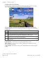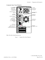
1
gvrSX™ Conversion Instructions
&
System Manual
040-0050-01 Rev A
! Read this manual before installing the Game.
! Keep this manual with the machine at all times.
www.globalvr.com
service.globalvr.com
[email protected]
408.597.3400
© 2004 GLOBAL VR, INC. All Rights Reserved
Operation Blockade, Infogrames and the Infogrames logo are trademarks of Infogrames Entertainment. S.A. Beach Head 2000, Beach Head
2002, and Beach Head 2003: Desert War are trademarks of Digital Fusion Inc and are used under license by Infogrames.
All other trademarks are the property of their respective owners.
Preface
Table of Contents
Preface
.......................................................3
Safety ...........................................................3
Warnings ...................................................3
Environmental Conditions ........................3
FCC Notices (United States).....................4
Section 1 – Game Description .....................5
Section 2 – Cabinet Conversion...................6
Upgrade Steps ..............................................6
Clean and Prepare the Cabinet.....................6
Remove old Tournament Header
and Card Reader.....................................7
Conversion Kit Contents and
Replacement Parts List ..........................8
Replace the Monitor (Optional) .................10
Remove the Old Monitor ........................10
Adapt the Cabinet for the Larger
Monitor ................................................10
Install the New Monitor ..........................12
Install the Cabinet Exhaust Fan .................13
Set Up the Hardware..................................15
Set Up AC Power Distribution................15
Remove the Game PCB and Install
New Hardware .....................................16
Connect the Jamma Conversion
Board and UVC....................................17
Install the Happ UGCI Board .................18
Set Up the Computer...............................19
Connect the Computer ............................20
Secure the Computer...............................21
Upgrade the Control Panel.........................22
Prepare the Control Panel .......................22
Apply Control Panel Graphics ................22
Install Buttons and Connect Wiring........23
Apply the Cabinet Graphics and
Marquee Artwork .................................24
Apply the Serial Number Sticker ............25
Section 3 – Power ON and Test the
Cabinet .....................................................26
Run the Joystick Calibration Utility ..........26
Adjust the Universal Video
Converter (UVC) .................................27
GVR SX Conversion System Manual
Page 2 of 48
Section 4 – Using the Game Operator
Menu .....................................................28
Setting Game Options and Resets..............28
Machine Menu ...........................................29
Game Mode Menu .....................................30
Game Resets Menu ....................................31
Coin Audits ................................................32
Game Purchase Audit.................................32
Game Selection ..........................................33
Player Control Test.....................................33
Monitor Calibration Test............................34
Section 5 – Starting a Game.......................35
Playing a Beach Head Game......................36
USB Game Dongles...................................37
Section 6 – System Software CDs .............38
Operating System Restore CD ...................38
Game Software CDs ..................................38
Section 7 – Troubleshooting ......................39
Section 8 – Diagrams and Schematics .......43
Computer Rear Panel Diagram ..................45
Warranty Service........................................46
Warranty Information..............................46
Technical Support ......................................48
Table of Figures
Figure 1. Drilling Cabinet Air Holes.............13
Figure 2. Typical Jamma Conversion
Board and UVC Connections...............17
Figure 3. Happ UGCI Board
Connections..........................................18
Figure 4. Finished Control Panel...................22
Figure 5. Simplified Wiring Diagram ...........43
Figure 6. Detailed Wiring Diagram...............44
Figure 7. Computer Rear Panel
Diagram................................................45
040-0050-01 Rev. A 10/29/2004
Preface
Preface
Safety
Please read this page before preparing your arcade cabinet for game play.
The following safety instructions apply to all game operators and service personnel. Specific
warnings and cautions will be included throughout this manual.
Use the following safety guidelines to help protect the system from potential damage and to
ensure your personal safety:
•
Make sure that the switch on the back of the computer is set to match the AC power in
use at your location:
115 volts / 60Hz in most of North and South America and some Far Eastern countries
such as Japan, South Korea and Taiwan
230 volts / 50Hz in most of Europe, the Middle East and the Far East
•
•
•
•
•
•
•
To help prevent electric shock, plug the system into a properly grounded power source.
The cables are equipped with 3-prong plugs to help ensure proper grounding. Do not use
adapter plugs or remove the grounding prong from a cable. If you must use an extension
cable, use a 3-wire cable with properly grounded plugs.
To help protect your system from sudden increases and decreases in electrical power, use
a surge suppressor, line conditioner, or Uninterruptible Power Supply (UPS).
Be sure nothing rests on the system's cables and that the cables are not located where they
can be stepped on or tripped over.
Do not spill food or liquid on the cabinet.
Do not push any objects into the openings of the system—doing so can cause fire or
electric shock by shorting out interior components.
Keep your system far away from radiators and other heat sources.
Do not block cooling vents.
Warnings
To avoid electrical shock, unplug the cabinet before performing the
installation procedures.
GLOBAL VR® assumes no liability for any damages or injuries incurred while
setting up or servicing the cabinet. Only qualified service personnel should
perform installation or service procedures!
Environmental Conditions
Cabinet is intended for indoor use only. Be sure to keep the cabinet dry and maintain
operating temperatures of 10°-40°C (50°-104°F).
040-0050-01 Rev. A 10/29/2004
© 2004 GLOBAL VR ® , INC.
Page 3 of 48
Preface
FCC Notices (United States)
Electromagnetic Interference (EMI) is any signal or emission radiated in free space or
conducted along power or signal leads, that endangers the functioning of radio navigation or
other safety service, or that seriously degrades, obstructs, or repeatedly interrupts a licensed
radio communications service. Radio communications services include, but are not limited
to, AM/FM commercial broadcast, television, cellular services, radar, air-traffic control,
pager, and Personal Communication Services (PCS). These licensed services, along with
unintentional radiators such as digital devices (including computer systems) contribute to the
electromagnetic environment.
Electromagnetic Compatibility (EMC) is the ability of items of electronic equipment to
function properly together in the electronic environment. While this computer system has
been designed and determined to be compliant with regulatory agency limits for EMI, there
is no guarantee that interference will not occur in a particular installation. If this equipment
does cause interference with radio communications services, which can be determined by
turning the equipment off and on, you are encouraged to try to correct the interference by one
or more of the following measures:
•
•
•
Re-orient the receiving antenna.
Relocate the cabinet relative to the receiver.
Plug the game into a different outlet so that the computer and the receiver are on different
branch circuits.
If necessary, consult a Regulatory EMC representative of GLOBAL VR® or an experienced
radio/television technician for additional suggestions. You may find the FCC Interference
Handbook, to be helpful. It is available from the U.S. Government Print Office, Washington,
DC 20402.
This device has been tested and complies with the limits for a Class A digital device pursuant
to Part 15 of the FCC Rules. These limits are designed to provide reasonable protection
against harmful interference when the equipment is operated in a commercial environment.
This equipment generates, uses, and can radiate radio frequency energy. If not installed and
used in accordance with the instruction manual, it may cause harmful interference with radio
communications. Operation of this equipment in a residential area is likely to cause harmful
interference, in which case you will be required to correct the interference at your own
expense.
Operation is subject to the following conditions:
•
•
This device may not cause harmful interference.
This device must accept any interference received, including interference that may cause
undesired operation.
gvrSX™ Conversion System Manual
Page 4 of 48
040-0050-01 Rev. A 10/29/2004
Section 1 – Game Description
Section 1 – Game Description
The GLOBAL VR® gvrSX™ Conversion Kit lets operators convert old Jamma cabinets for
the same game play as the GLOBAL VR® Vortek cabinet. The Conversion Kit uses the
existing cabinet, coin inputs, speakers, and Jamma harness.
The gvrSX™ design showcases the following features:
•
•
•
Superior graphics.
Easily upgradeable with exciting new game software.
Four real motion axes: yaw (turn) left/right rotation, and pitch (tilt) up/down.
The conversion kit utilizes a state-of-the-art PC-based interactive visual computing system.
The GLOBAL VR® Multi-Game software shell allows multiple games to be installed and
played on one cabinet at any time. This PC-based configuration provides the advantage of
follow-on periodic new game releases for the cabinet, and the ability to accommodate
virtually any new, future 3D PC game that would be enhanced by the addition of motion
control for the Arcade Industry.
gvrSX™ provides the following benefits to operators:
•
•
•
•
Consistent earnings from proven game operators for all generations.
Multi-Game Shell. Upgrade and install new games for the gvrSX™ platform at any time.
Players can choose from multiple games on one cabinet.
Multiple games are available for each cabinet, including the top earners: Beach Head
2000, Beach Head 2002, and Beach Head 2003: Desert War, with regular new releases.
Superior reliability.
040-0050-01 Rev. A 10/29/2004
© 2004 GLOBAL VR ® , INC.
Page 5 of 48
Section 2 – Cabinet Conversion
Section 2 – Cabinet Conversion
Converting your cabinet consists of the primary steps listed below. Exact steps may vary
depending on your cabinet.
Upgrade Steps
•
•
•
•
•
•
Clean and Prepare your Cabinet: Remove all graphics and labels, tournament header,
and card reader, and clean the cabinet (page 6).
Install the New Monitor: Do this if you purchased the monitor upgrade kit with the 27inch monitor (page 10). Otherwise, you will install the Universal Video Converter
(UVC) card to adapt the existing monitor to work with the new hardware.
Install the Fan and Drill Ventilation Holes: Improve cabinet cooling to accommodate
the new computer (page 13).
Set Up the Hardware: Install the new computer, UGCI Board, Jamma Conversion
Board, and UVC (if used) and make all connections (page 17).
Upgrade the Control Panel: Upgrade your control panel with the new controls and
artwork (page 22).
Apply the Cabinet Graphics: Install the new cabinet graphics and labels (page 27).
Clean and Prepare the Cabinet
GLOBAL VR® requires that all converted cabinets meet the guidelines for finished cabinet
artwork described in this instruction manual.
You must remove all previous artwork, serial numbers, and labels from the cabinet before
installing the gvrSX™ artwork. Make sure the new cabinet artwork is setup as instructed in
this manual. Clean the cabinet well so that the new graphics will adhere properly.
gvrSX™ Conversion System Manual
Page 6 of 48
040-0050-01 Rev. A 10/29/2004
Section 2 – Cabinet Conversion
Remove old Tournament Header and Card Reader
If your cabinet has an existing tournament header or card reader, these components can be
removed. They are not used by the gvrSX™ system.
The card reader is usually located near the coin door. The header is usually located at the top
of the cabinet. Perform the following steps to remove the card reader and tournament header:
1. Unplug the data cables from the card reader and remove them from the cabinet.
2. Un-bolt the card reader and use the same carriage bolts to install a card reader blank plate
(not provided).
3. Unplug the cables from the tournament header and remove them from the cabinet.
4. Un-bolt the tournament header and remove it from the cabinet.
040-0050-01 Rev. A 10/29/2004
© 2004 GLOBAL VR ® , INC.
Page 7 of 48
Section 2 – Cabinet Conversion
Conversion Kit Contents and Replacement Parts List
Table 1.
Conversion Kit Components
Electronic Components
Description
Qty
Part Number
System Computer (Not Shown)
1
DFI-CS35-TLGVRSX
UGCI board, HAPP Flying
1
95-0800-20
Joystick, Pup, Analog with Atari Grips
1
95-0923-GVR
White Pushbutton W/ Micro Switch
4
47-9150-02
JAMMA Conversion Board
1
990-0007-01
Universal Video Converter (UVC) Card
1
96-0583-00
DONGLE, USB, KQRTG
1
USB-KQRTG
PS2-Keyboard (Not Shown)
1
PS2-KEYBOARD
7-Outlet Power Strip with Surge
Protector (Not Shown)
1
49-0963-40
Description
Qty
Part Number
Cable, UVC to JAMMA
1
115-0018-01
Cable, UGCI Coin & Op to JVC Coin &
Op (Not Shown)
1
115-0062-01
Cable, VGA, 6 foot, M/M
1
V-0606
Cable, USB
2
USB-AB06MM
Cable, PC Y-Power
1
PGAK-FLT-3500-08
Cable, Coin Harness Assy (Not Shown)
1
95-0002-014
Cable, 3.5mm Audio, 6Ft
1
96-0539-00
Standoff, 3" tall .156 hole Screw-Down
(For UVC and Jamma Board)
8
LCBS-L-5-01
PCB Mounting Feet Set of 4
(for UGCI Board)
1
49-1019-00
Button Plug (Black)
1
52-6212-00
Cables & Miscellaneous Hardware
DFI Computer Mount (Not Shown)
2
V2-0183-00
#10 x 1/2" Course-Thread Wood Screw
4
10N50PPAZZ
1/4-20 x 3/4" Phillips Pan Screw
2
25C37PPMZZ
6-32 X 1/2 Pan-Head Wood Screw
8
4600-0032
1/4-20 Nylon Lock Hex Nut
2
4600-0033
18AWG Butt Connector
3
PGAK-2A0701
#8 Hole 18 AWG Ground Ring
1
PGAK-5A890
18AWG .250 Spade
2
PGAK-KTN50
gvrSX™ Conversion System Manual
Page 8 of 48
040-0050-01 Rev. A 10/29/2004
Section 2 – Cabinet Conversion
CDs, Labels, and Manuals
Description
Qty
Part Number
Conversion Instructions & System Manual (This
Document)
1
040-0050-01
Document, Software Restore
1
040-0060-01
Software, Game, Beach Head 2003: Desert War
1
050-0040-01 1
Software, Game, Beach Head 2000
1
050-0016-01 1
Software, Game, Beach Head 2002
1
050-0017-01 1
Software, V3 and gvrSX™ Recovery Disk XP
Home, Multi Game Upgrade
1
050-0019-01 1
Software, Joystick Calibration Utility CD
1
050-0022-01
Serial Number Label
1
L-0039
Microsoft Windows XP, Home
1
WINXP-HOME
Description
Qty
Part Number
Side Decal
2
SX-AW-09
Marquee Artwork
1
SX-AW-08
Control Panel Background Artwork
1
SX-AW-07
FIRE Decal
2
SX-AW-01
CANNON Decal
2
SX-AW-02
MISSILES Decal
2
SX-AW-03
GVR Console Logo
1
SX-AW--4
Joystick Decal
1
SX-AW-06
Console Logo
1
SX-AW-05
Artwork
Table 2.
Optional Monitor Upgrade Kit Components (Part #: PGA-UPGRADE-MTR)
Description
Qty
Part Number
DOC, Instructions for relocating mounting holes
1
040-0045-01
1/4 X 1.0 Carriage Bolt, Stl/Znc
4
4600-0013
1/4" Flat Washer SAE Stl/Znc
4
4600-0014
Nut, 1/4-20 Kepnut Stl/Znc
4
4600-0015
Monitor Bezel 28"
1
49-0106-01
Monitor, Wells-Gardner 27" SVGA
1
WGM2792-UOTS19C-MOD
Template, Monitor Bracket Mounting Holes
1
L-0059
040-0050-01 Rev. A 10/29/2004
© 2004 GLOBAL VR ® , INC.
Page 9 of 48
Section 2 – Cabinet Conversion
Replace the Monitor (Optional)
Note: Do Not use the Universal Video Controller (UVC) board with the Wells Gardner®
monitor.
If you have the Monitor Upgrade Kit, perform the steps in this section to remove the old
monitor and install the 27-inch Wells-Gardner® monitor.
Remove the Old Monitor
1. Open the service shelf, and remove the glass display shield and monitor bezel.
2. Disconnect ALL wiring from the back of the monitor. Make sure that no wires still
connected to the monitor are tied to the cabinet.
3. Remove the four (4) monitor retaining nuts and washers and save them for reinstallation.
4. Remove the monitor from the cabinet. It is advisable to have at least two people to
support the weight of the monitor.
5. Proceed to the next section and install the new monitor.
Adapt the Cabinet for the Larger Monitor
If your cabinet already had a 27-inch monitor, you should be able to proceed to the next
section and install the monitor.
If your cabinet had a 25-inch monitor, refer to the figure that follows, and perform the
following steps to adapt the cabinet hardware for the larger, 27-inch Wells-Gardner®
monitor:
1. Note the positioning of the lower monitor bracket to aid in reinstallation. Remove the
nuts and bolts that secure the lower monitor bracket to the cabinet. Remove the bracket
and save it for reinstallation. Perform the following steps to drill new bolt holes for the
bracket to relocate it for the larger monitor.
2. Refer to the figure below and mark straight lines, as shown, through the center of the two
sets of bolt holes and about 2" below. Drill two ¼" diameter bolt holes 1-7/16" below the
original holes, and along the same centerline. Use the template from the kit (part #:
L-0059) to aid in placing the holes.
3. The overall distance between the bolt heads on the side of the cabinet must be 20-3/4"
center-to-center in the long direction, and 1-9/16" center-to-center in the short direction.
gvrSX™ Conversion System Manual
Page 10 of 48
040-0050-01 Rev. A 10/29/2004
Section 2 – Cabinet Conversion
4. Repeat the previous two steps to drill bolt holes in the other side of the cabinet.
5. Align the lower monitor bracket with the new bolt holes and bolt it in place using the nuts
and bolts removed previously.
6. Install the four (4) supplied carriage bolts into the original bolt holes to give them a
finished appearance.
040-0050-01 Rev. A 10/29/2004
© 2004 GLOBAL VR ® , INC.
Page 11 of 48
Section 2 – Cabinet Conversion
Install the New Monitor
1. Refer to the picture below and make sure that the monitor frame of the new 27-inch
Wells-Gardner® Monitor has the holes required to mount it to the cabinet brackets. Both
the top and bottom sections of the frame must have two pairs of holes (some monitor
frames have only one pair of holes in each section). The inside pair of holes must be
centered on the bracket, and measure 19-1/4" center-to-center.
2. If the monitor frame does not have the required holes, drill them in both the top and
bottom frame sections as follows: Drill two (2) 3/8" diameter holes, centered, 19-1/4"
apart. Each of these new holes should be approximately 11/16" inboard from the existing
holes, and on the same horizontal centerline.
Caution: Avoid getting drill chips in the electronic components.
CAUTION: The monitor is very heavy. Monitor installation requires at least two
people. It is best to have a third person handling the monitor frame from inside the
cabinet back door. It is easy to catch fingers between the monitor frame and cabinet.
3. To install the monitor, first install the lower edge of the monitor onto the lower bracket
studs, and then rotate the monitor downwards to catch on the upper bracket studs. This
will require at least two people. It may be best to have a third person handling the
monitor frame from inside the back door. Watch your fingers; this monitor is very heavy.
gvrSX™ Conversion System Manual
Page 12 of 48
040-0050-01 Rev. A 10/29/2004
Section 2 – Cabinet Conversion
4. Use the old hardware to re-attach the monitor to the cabinet bracket (four places).
5. Install the new monitor bezel.
6. Clean and replace the glass display shield.
7. Replace the small retainer tab that secures the display shield in place.
8. Mount the monitor remote control board in a convenient location in the service tray.
9. Connect the monitor ground wire to a ground lug on the cabinet.
10. If the old monitor was powered with an AC isolation transformer, remove the transformer
from the cabinet. The new monitor will connect directly to the AC power strip, to be
installed in the next section.
Install the Cabinet Exhaust Fan
An exhaust fan is required to keep the temperature inside the cabinet cool enough for the
computer to operate properly.
If you experience blank screens or rebooting issues, this could be due to excessively high
temperatures inside the cabinet. Drilling more air holes in the lower rear of the cabinet, as
described in step 1 below, should improve airflow and reduce cabinet temperatures.
Perform the following steps to install the exhaust fan and drill air holes:
1. Using a 1/2" drill bit, drill six to eight air holes in the lower rear of the cabinet, as shown
in Figure 1. Be careful not to damage any wires or components while drilling.
6-8 1/2" Air Holes
Place low in cabinet. Position so as to
avoid drilling into wires or components.
Figure 1.
Drilling Cabinet Air Holes
2. Using a screwdriver, remove the metal or plastic grill covers that cover the ventilation
slots on the back of your cabinet. Push in on each corner of the metal grill and they will
pop out and fall to the bottom of the cabinet.
040-0050-01 Rev. A 10/29/2004
© 2004 GLOBAL VR ® , INC.
Page 13 of 48
Section 2 – Cabinet Conversion
3. Install the exhaust fan behind the ventilation slot, just above the rear cabinet door, as
shown by the arrow in the picture below.
4. Place the exhaust fan on the outside of the ventilation slots and use the mounting holes in
the fan as a template to drill the mounting holes. Use an 11/64" drill bit to drill the four
mounting holes for the exhaust fan.
5. Place the fan on the inside of the cabinet so that it will blow air out of the cabinet. Use
the 8-32 x 2 inch screws with nuts to secure the fan to the cabinet, as shown in the picture
above.
6. Plug the fan into the AC power strip inside the cabinet, and verify that the fan blows air
out of the cabinet.
gvrSX™ Conversion System Manual
Page 14 of 48
040-0050-01 Rev. A 10/29/2004
Section 2 – Cabinet Conversion
Set Up the Hardware
Set Up AC Power Distribution
You must install the AC power strip/surge suppressor from the kit to provide power to the
computer, new monitor (if installed), and ventilation fan.
The actual wiring will vary depending on which cabinet you are converting. Use the
instructions that follow as a general guideline for setting up AC power distribution.
1. Locate the AC power panel inside the cabinet. The panel is usually the distributing point
for all of the AC power lines inside the cabinet. If the panel is on the floor of the cabinet,
you will need to move it to one of the side walls to make enough room to secure the
computer to the bottom of the cabinet.
2. Disconnect the two AC power lines and the ground wire that connect to the ON/OFF
switch on the AC power panel, as shown by the arrows in the picture above.
3. Strip these three wires and connect them to the AC power cord from the kit, using the
wire crimps provided. (You will be plugging this power cord into the power strip.)
4. Connect the power and ground wires from AC power strip to the three connectors on the
ON/OFF switch where you removed the wires in step 2, as shown by the arrow in the
picture above.
5. Plug the AC power cord you spliced in step 3 into the AC power strip. All cabinet AC
power should now be routed through the power strip.
040-0050-01 Rev. A 10/29/2004
© 2004 GLOBAL VR ® , INC.
Page 15 of 48
Section 2 – Cabinet Conversion
6. Some older cabinets with CGA monitors have an AC isolation transformer that is used to
power the monitor. These are often bulky, heavy transformers that take up most of the
space on the bottom of the cabinet, and they cannot be removed unless you replace the
monitor. If you connect a monitor that requires an AC isolation transformer directly into
an AC power source, you will damage the PCB chassis on the monitor.
7. If your cabinet has an AC isolation transformer for the monitor, find the AC power lines
that power the AC isolation transformer and splice them to an AC power cord (not
provided in the kit), so you can connect this to the AC power strip. You may need to
reposition the AC isolation transformer to make room to install the computer on the floor
of the cabinet. (Note: The new Wells-Gardner® monitors do not use an AC isolation
transformer. If you are installing this monitor, you can safely remove the transformer.)
Remove the Game PCB and Install New Hardware
Caution: Power must be off when connecting boards. To prevent damage from
electrostatic discharge (ESD), handle PCBs by the edges only and use a grounding wrist
strap or similar precaution.
1. The Conversion Kit hardware uses the existing Jamma harness wiring for speakers, video
(for an existing monitor), and coin inputs. Remove the Game PCB and any other
hardware from the old game, but keep the existing DC power supply and Jamma harness
wiring in place.
2. Install four small plastic feet from the kit on the Jamma conversion board, and on the
UVC if you are installing one.
gvrSX™ Conversion System Manual
Page 16 of 48
040-0050-01 Rev. A 10/29/2004
Section 2 – Cabinet Conversion
3. Set jumper J8 on the Jamma conversion board to pins 1 and 2 for stereo, or pins 1 and 3
for mono audio, depending on how your cabinet audio is set up.
4. Place the boards next to each other in the service tray where you removed the old boards.
Make sure that the Jamma connector on the Jamma wire harness can reach the Jamma
Conversion Board before securing the boards to the cabinet.
5. Secure the boards with wood screws in the plastic feet.
Connect the Jamma Conversion Board and UVC
Figure 2.
Typical Jamma Conversion Board and UVC Connections
Refer to the figure above, and Figure 5, Simplified Wiring Diagram, on page 43, and perform
the following steps to connect the Jamma harness wiring and other cables to the Jamma
Conversion Board:
1. Connect the Jamma connector from the Jamma harness to the Jamma edge on the Jamma
Conversion Board.
2. Connect the Video Input, J4 on the Jamma Conversion Board to the video output port on
the Video Converter board, if used, or to the VGA port on the computer video card.
3. Connect the existing PC power supply in the cabinet to the Jamma Conversion Board
PWR IN port using the PC Y-power cable from the kit.
Note: The PC Y-power cable uses a standard PC power supply connection found on
most DC power supplies used in arcade cabinets. If your existing power supply does not
have this type of connector, you will need to splice the Y-Power cable into the power
supply on the cabinet. Here are the specifications for the PC Y-power cable:
•
•
•
Red Wire
Yellow Wire
Black Wire
+5 VDC
+12 VDC
Ground
040-0050-01 Rev. A 10/29/2004
© 2004 GLOBAL VR ® , INC.
Page 17 of 48
Section 2 – Cabinet Conversion
Install the Happ UGCI Board
1. Install four small plastic feet from the kit on the Happ UGCI board.
2. Mount the board below the control panel where the button and joystick harnesses will
reach it, as shown in Figure 3.
3. Secure the board with wood screws in the plastic feet as shown in Figure 3.
4. Refer to the figure below, and Figure 5, Simplified Wiring Diagram, on page 43 to
connect the Happ UGCI board.
Figure 3.
Happ UGCI Board Connections
5. Connect the button harness to J4 on the UGCI board.
6. Connect the joystick harness to J6 on the UGCI board.
7. Connect the coin meter operator button harness (part #: 115-0062-01) to J3 and J5 of the
UGCI board, as shown on the labels on the harness. Route the other end to the service
tray and connect it to J7 on the Jamma Conversion Board. Secure the harness with a
cable tie as shown in Figure 3.
8. Coil the old button harnesses and secure them with a cable tie as shown in Figure 3.
gvrSX™ Conversion System Manual
Page 18 of 48
040-0050-01 Rev. A 10/29/2004
Section 2 – Cabinet Conversion
Set Up the Computer
The computer comes pre-loaded with the game software. There is no need to reload the
software with the CDs in the kit. The Software recovery CDs are included in case you have a
software problem in the future or wish to change the specific game titles available.
CAUTION: The computer can be damaged very easily. Use caution when installing
the computer. Avoid touching internal components. These components are susceptible
to Electrostatic Discharge (ESD) damage.
1. Remove the right side panel from the computer by removing the two screws that hold the
panel in place, as shown by the arrows in the picture below. Slide the panel back and
then out to remove it from the computer chassis.
2. Place the computer on its side so you can clearly see the inside of the computer. Place
the metal computer bracket so that the tab is pointed down, and hook the tab into the
bottom mounting hole on the computer, as shown in the picture below.
3. Use the flat-head screw with nylon locking nut to secure the bracket to the top hole of the
computer chassis.
4. Repeat steps 2 and 3 for the second mounting bracket.
5. When finished, the two screws with nuts should be closest to the outside edge of the
computer chassis, with the bracket tabs hooked into the holes closest to the motherboard,
as shown in the last part of the picture above. Re-install the side panel on the computer.
040-0050-01 Rev. A 10/29/2004
© 2004 GLOBAL VR ® , INC.
Page 19 of 48
Section 2 – Cabinet Conversion
Connect the Computer
Refer to Figure 7, Computer Rear Panel Diagram, on page 45, and Figure 5, Simplified
Wiring Diagram, on page 44 to make the connections to the computer.
1. Connect the USB hub to one of the computer USB ports and install the game dongles in
the USB hub. Refer to the section titled USB Game Dongles on page 37 for more
information on the dongles and USB hub.
2. Connect the audio cable from the green audio port of the computer to J2 of the Jamma
Conversion Board.
3. Connect the video cable from the computer VGA port to J1 of the UVC (if used) or the
monitor.
4. Connect the USB cable from the computer USB port to the UGCI board.
Important: The USB connector from the UGCI board must be connected directly to the
USB port on the computer, not to the USB hub.
5. Secure the wires to the cabinet so they do not get pinched or torn if the cabinet has a
sliding control panel.
6. Connect the power cord from the computer to the AC power strip.
gvrSX™ Conversion System Manual
Page 20 of 48
040-0050-01 Rev. A 10/29/2004
Section 2 – Cabinet Conversion
Secure the Computer
Caution: Use caution to avoid damaging the computer. Always power OFF the cabinet
before moving the computer.
Once you have verified that everything is working properly, secure the computer to the
cabinet. You will need a 6-inch clearance in the front of the computer to allow the CD-ROM
drive tray to fully OPEN. Secure the computer to the bottom of the cabinet using four (4) #10
x ½" Phillips wood screws.
040-0050-01 Rev. A 10/29/2004
© 2004 GLOBAL VR ® , INC.
Page 21 of 48
Section 2 – Cabinet Conversion
Upgrade the Control Panel
Perform the steps in this section to upgrade the old control panel with new buttons, joystick,
and graphics.
Prepare the Control Panel
1. Disconnect the wires from the buttons and other controls.
2. Remove the nuts and bolts that hold the plastic cover to the control panel surface.
3. Remove the buttons, trackball (or other controls), the clear plastic cover, and artwork
from the control panel.
4. Install the joystick in the control panel using the four nuts and bolts removed from the
trackball assembly. You may need to remove the handle from the joystick to install the
control panel artwork and plastic cover.
Apply Control Panel Graphics
Refer to the picture of the finished control panel, Figure 4, as you place the graphics on the
control panel. The exact position of each sticker will depend on the size and shape of your
control panel, but the finished control panels should look like Figure 4.
Figure 4.
Finished Control Panel
Note: To aid in placing graphics, spray the cabinet surfaces with soapy water or spray
cleaner before applying each graphic. This allows you to reposition the graphic easily. Once
you are satisfied with placement, use a squeegee to force the liquid out from under the
graphic.
1. Set the background graphic over the control panel and determine placement. Once you
are satisfied with the placement, peel off the backing and apply the graphic.
2. Using a new Exacto® knife, use the outside edge of the control panel as a guide to cut off
the excess control panel background graphic material.
3. Cut the excess graphic material from the button and joystick holes.
gvrSX™ Conversion System Manual
Page 22 of 48
040-0050-01 Rev. A 10/29/2004
Section 2 – Cabinet Conversion
4. Place the joystick direction sticker over the joystick hole. Make sure that it is properly
aligned with the cabinet and monitor and then peel off the backing and apply the sticker.
If the sticker has protective paper over the face, wet the paper and wait about 15 minutes
before removing it to avoid damaging the artwork.
5. Center the button function stickers about 3/4-inch below the button holes as shown in the
picture that follows. The Missiles buttons are outboard and the cannon buttons are
inboard. Once the graphics are lined up properly, peel off the backing and apply each
sticker.
6. Once all of the control panel graphics have been applied, re-install the clear plastic
control panel cover and secure it with the nuts and bolts removed previously.
Install Buttons and Connect Wiring
1. Install the buttons on the control panel.
2. If your cabinet has an extra button hole that is not used by the gvrSX™ system, install the
button plug from the kit to cover the unused button hole.
3. Re-install the joystick handle.
4. Connect the joystick harness to the joystick.
5. Refer to the labels on each wire of the button harness and connect the wires to the correct
buttons. Note that the trigger button wires connect to the joystick.
6. Use wire ties to secure the wires so that they won’t get pulled or pinched when the
control panel and service tray are opened or closed, as shown in the figure below.
040-0050-01 Rev. A 10/29/2004
© 2004 GLOBAL VR ® , INC.
Page 23 of 48
Section 2 – Cabinet Conversion
Apply the Cabinet Graphics and Marquee Artwork
GLOBAL VR® requires that all converted cabinets adhere to the strict guidelines for finished
cabinet artwork as described in this instruction manual. Perform the following steps to apply
the side panel graphics and replace the old marquee artwork.
1. Place a gvrSX™ Logo sticker on each side of the cabinet, centered, level to the ground, at
about eye level, as shown in the picture below. After determining placement, peel off the
backing and apply the graphic stickers.
2. Remove the screws from the top bracket that holds the marquee glass and artwork to the
cabinet, as shown by the arrows in the picture below.
3. Clean both sides of the marquee glass.
4. Insert the new marquee graphic. Center it in the marquee and trim the excess graphic
material from the edges as necessary.
5. Re-install the glass and top bracket.
gvrSX™ Conversion System Manual
Page 24 of 48
040-0050-01 Rev. A 10/29/2004
Section 2 – Cabinet Conversion
6. If your cabinet has existing tournament rules artwork located between the speakers and
just above the monitor, remove the screws around the metal plate that holds both the
artwork and the speakers to the cabinet, as shown by the arrows in the picture below.
7. Remove the metal plate and replace the old artwork with the new gvrSX™ game
graphics.
Apply the Serial Number Sticker
Place the serial number sticker from the kit on the outside of the cabinet in the upper lefthand corner, as shown by the arrow in the picture below.
This completes the cabinet conversion. Proceed to the next section to verify proper operation
and calibrate the joystick.
040-0050-01 Rev. A 10/29/2004
© 2004 GLOBAL VR ® , INC.
Page 25 of 48
Section 3 – Power ON and Test the Cabinet
Section 3 – Power ON and Test the Cabinet
Before powering the cabinet ON for the first time, please verify the following:
•
•
•
AC power is correctly setup inside the cabinet.
The DC power supply is correctly setup to provide power to the Jamma Conversion
Board.
All connections are correct and secure.
Once you have verified that all hardware is installed correctly, power ON the cabinet and
verify that the game starts and runs properly, and that all controls function properly.
Use the Player Control Test (see page 33) from the Operator Menu to verify that the joystick
and buttons are working properly.
Insert some coins and verify that the coin inputs are working properly.
Start a game (see page 35) and verify that it plays properly.
Run the Joystick Calibration Utility
The Joystick Calibration Utility adjusts the software to match the joystick motion. Run the
Joystick Calibration Utility whenever you replace the joystick or install game software on the
system.
1. Insert the Joystick Calibration Utility CD in the computer CD-drive. The CD will run
automatically. You will see a series of processing screens, followed by windows telling
you to move the joystick in certain ways.
2. Move the joystick as instructed by the onscreen prompts.
3. Ignore the windows that refer to "Throttle" and "Rudder." Simply click the trigger to exit
from these windows.
gvrSX™ Conversion System Manual
Page 26 of 48
040-0050-01 Rev. A 10/29/2004
Section 3 – Power ON and Test the Cabinet
Adjust the Universal Video Converter (UVC)
The Universal Video Converter (UVC) is designed to work with most EGA and CGA arcade
monitors. When you power the cabinet up for the first time, you may need to adjust the
settings on the UVC board to match the monitor. To correctly set up the UVC, you must
know the resolution and Horizontal and Vertical Sync setup of the monitor.
Depending on your cabinet, the J7 video output of the UVC can be connected directly to the
video input on the monitor, or to J4 on the Jamma Conversion Board to route the signals
through the Jamma harness to the monitor.
Table 3.
UVC DIP Switch Settings
SW 1 & 2
Both normally ON.
SW 3
Output Resolution
ON: CGA = 640 x 200 @ 15.72 KHz
OFF: EGA = 640 x 384 @ 24.5 KHz
SW 4 and 5
Input Resolution
Both normally ON to auto detect the video resolution.
SW 6
H Sync Signal
Normally ON. Changing the H Sync signal will move the entire picture left or right.
Change this setting if you find the picture is too far to one side and you cannot
adjust it using the monitor remote control panel.
SW 7
V Sync Signal
Normally ON. Changing the V Sync signal will move the entire image up or down.
Change this setting if you find the image is too far up or down on the monitor, and
you cannot adjust it using the monitor remote control panel.
SW 8
H-V / Composite
Sync
ON: Composite sync, for monitors with one composite (combined) sync line
(most CGA monitors).
OFF: For monitors with two separate H and V sync lines (most EGA monitors).
Change this setting only if you have no picture on your monitor.
040-0050-01 Rev. A 10/29/2004
© 2004 GLOBAL VR ® , INC.
Page 27 of 48
Section 4 – Using the Game Operator Menu
Section 4 – Using the Game Operator Menu
All gvrSX™ game audits, game adjustments, and control diagnostics are options of the Game
Operator Menu. Press the Operator Button behind the coin mech door in the cabinet to
activate the Game Operator Menu.
The screen shown below is the first screen that you will see after pressing the Operator
button. The Options menu is displayed on the left side of the screen, and the settings for the
selected option are displayed on the right. You do not see a mouse pointer when using the
joystick or trackball to navigate the Game Operators Menu; instead, each option or menu
button will highlight in yellow when it is ready to be selected.
Setting Game Options and Resets
Once in the Operator Menu, use the Joystick and Trigger and Buttons to navigate and set up
the game software, as described below:
1. Use the Joystick to navigate and highlight an item in the Options list.
2. Press the Trigger Button to open the menu for the selected Option.
3. Use the Joystick to move between the items in the window, and to scroll through the
available settings for each item.
4. To change a setting, use the joystick to scroll to the desired setting, and then press the
Trigger Button to set it.
gvrSX™ Conversion System Manual
Page 28 of 48
040-0050-01 Rev. A 10/29/2004
Section 4 – Using the Game Operator Menu
Machine Menu
The Machine menu is the default screen displayed when you press the Operator Button. It
displays the information described in the table below:
Serial #
Reserved for future use of Multi-Player or Tournament-Enabled Games.
Machine Type
Reserved for future use of Multi-Player or Tournament-Enabled Games.
Hardware Version
Reserved for future use of Multi-Player or Tournament-Enabled Games.
Inserted Credits
This tells the number of Credits and Coins that have been inserted on this
cabinet.
Reset Credit Button
This button is used to reset or zero out the Inserted Credits number on this
screen.
Attract Mode Sound
This sets up the Attract Mode to be with sound or without. The available
options are: OFF, Occasionally ON, and Always ON.
Attract Volume
This will adjust the volume for the game play. The options to choose from
are: OFF, Low, Medium Low, Medium, Medium High, High, and Deafening.
Note: Most volume adjustments are made from the Operator Menu. If you cannot get
desired results, you can adjust the volume using the Audio Volume potentiometers, R3 and
R4 on the Jamma Conversion Board (See Figure 2 on page 17).
040-0050-01 Rev. A 10/29/2004
© 2004 GLOBAL VR ® , INC.
Page 29 of 48
Section 4 – Using the Game Operator Menu
Game Mode Menu
The Game Mode menu is used to set up the type of money used at your location, the number
of coins that are needed to start a game, and game play timeout, as described in the table
below:
Credit Display
Defines whether Money or Arcade Credits are used to play this cabinet. The
options to choose from are: Money, or Credits.
International Settings
Defines the type of money that will be used in this cabinet. The options
available are: U.S.A., or U.K. Changing between these two options
automatically changes the Coins per $, Credits per Game, and Credits per
Continue settings.
Coins Per $
(or Coins Per £)
This sets how many coin drops it takes to reach a dollar or pound. In the USA,
you would set this to 4, because 4 quarters equal one dollar. In the UK, you
would set this to 10 if the game is setup for 10-pence coins. The options to
choose from are 1—20.
Play Mode
This will turn free play ON or OFF. The options to choose from are:
Coin/Money Mode, or Free Play.
Credits Per Game
This number defines how many coins or credits it will take to start a Game.
Credits Per Continue
This number defines how many coins or credits it will take to continue a current
Game.
Starting Game Time
This number defines how long a player’s game will last in seconds before the
Continue Game Message appears.
Continue Time
This number defines how many seconds a continued game will last before the
next Continue Game Message appears.
gvrSX™ Conversion System Manual
Page 30 of 48
040-0050-01 Rev. A 10/29/2004
Section 4 – Using the Game Operator Menu
Game Resets Menu
The Game Resets menu allows you to restore the cabinet to the default settings, and delete
various coin and game stats, as described in the table below:
Restore Factory
Settings
Sets the Game Mode optional settings to the Factory Settings listed below.
U.S.A. Factory Settings
U.K. Factory Settings
Credit Display
Money
Credit Display
Money
International Setting
U.S.A.
International Setting
U.K.
Coins Per $
4
Coins Per $
10
Play Mode
Coin/Money
Mode
Play Mode
Coin/Money
Mode
Credits Per Game
4
Credits Per Game
5
Credits Per Continue
4
Credits Per Continue
5
Starting Game Time
160 Sec
Starting Game Time
160 Sec
Continue Time
140 Sec
Continue Time
140 Sec
All Audit Coin Stats
Resets the Coin Audits menu for the cabinet. This reset does not affect the
Lifetime Records stored by the game.
All Audit Game Stats
Resets the Game Purchases Audits menu for the cabinet. This reset does not
affect the Lifetime Records stored by the game.
All High Score Stats
Resets the Player High Scores for the cabinet.
040-0050-01 Rev. A 10/29/2004
© 2004 GLOBAL VR ® , INC.
Page 31 of 48
Section 4 – Using the Game Operator Menu
Coin Audits
The Coin Audit menu shows the total number of coins collected for each game, and the
cabinet total, as well as the last date and time the stats were reset. The Lifetime Stats are
never reset and show the total number of Games Played for each installed game, and the
cabinet total.
Game Purchase Audit
The Game Purchase Audit menu shows the total number of Games Played for each game
installed, and the cabinet total, as well as the last date and time the stats were reset. The
Lifetime Stats are never reset and show the total number of Games Played for each installed
game, and the cabinet total.
gvrSX™ Conversion System Manual
Page 32 of 48
040-0050-01 Rev. A 10/29/2004
Section 4 – Using the Game Operator Menu
Game Selection
The Game Selection window allows you to disable installed games so that they are not
available to play in the multi-game selection window. Select a title and press the Trigger
Button to put an “X” next to the game that you want disabled. When you exit the Operator
Menu, the game will be unavailable for play in the Multi-Game Selection. The game is not
deleted, and can be re-enabled at any time by removing the “X” in the Game Selection Menu.
If you have installed a game and it does not appear in the Multi-Game Selection window
during Attract Mode, or in the Game Selection Menu, check to make sure the Game Dongle
is inserted correctly. When a USB Game Dongle is inserted correctly and recognized by the
Game Software, it should light up with a red LED.
Player Control Test
The Player Control Test will validate that the controls are set up correctly and working
properly. When you press a button, a red arrow will appear on the test screen to indicate
which button was pressed, as shown in the picture above. When you move the Joystick in
040-0050-01 Rev. A 10/29/2004
© 2004 GLOBAL VR ® , INC.
Page 33 of 48
Section 4 – Using the Game Operator Menu
any direction, a red arrow will indicate the direction that the Joystick is moving. When you
are finished testing the player controls, press the Operator Button to exit back to the main
Operator Menu.
Monitor Calibration Test
The Monitor Calibration Test shows a series of screens that allow you to adjust the monitor
using the monitor remote control panel. Use the joystick to scroll through each monitor test
screen. To exit the Monitor Calibration Test, press the operator button again.
Use the monitor calibration screens to adjust and fine-tune the picture on your monitor. Each
screen is designed to help you to either align the horizontal and vertical sync, or adjust the
white balance and color hues. If you notice a color distortion on the monitor, pressing the
degausser button on the monitor remote control panel may fix the color distortion.
Use the monitor remote control panel to adjust and fine-tune the picture on your monitor.
When you press a button on the panel, the Monitor Adjustment Options display on screen.
Use the buttons on the monitor remote control panel to select, adjust, and set the available
options. The monitor remote control panel is usually located under the Control Panel on the
cabinet.
gvrSX™ Conversion System Manual
Page 34 of 48
040-0050-01 Rev. A 10/29/2004
Section 5 – Starting a Game
Section 5 – Starting a Game
With the proper number of credits inserted, use the joystick to choose the game you want to
play, and press the Fire Button to confirm. If only a single game is installed on your cabinet,
you will not choose a game, but will go directly to the next screen.
At the next screen, choose the difficulty of play: Easy, Medium, or Hard. Each degree in
difficulty will add more enemy squadrons to the game and weaken your shield against the
enemy. Use the joystick to scroll through the options, and press the Trigger Button to
confirm.
040-0050-01 Rev. A 10/29/2004
© 2004 GLOBAL VR ® , INC.
Page 35 of 48
Section 5 – Starting a Game
Playing a Beach Head Game
Beach Head 2002, and Beach Head 2003: Desert War, both use the screen layout described
below. Beach Head 2000 uses a different layout for the Information Bars.
The goal of the game is to defend your post and destroy as much of the enemy as possible.
The Information Bars on the screen, described in the table below, provide useful information
about the game.
Ref.
Information Bar Description
A
This Information bar tells you how much of your shield you have left.
B
This Information bar tells you what level you have achieved in the game.
C
The Blue Information Bar tells you how many Enemy Aircraft remain for this level. The Red
Information Bar tells you how many Enemy Land Vehicles or Soldiers remain.
D
The Blue and Red Arrows tell you the direction the Enemy is coming from. When the enemy
comes into view on your monitor, the arrows disappear.
E
This shows your total score for the game. The more Enemies you strike down, the more
points you earn.
Cannon Button: Fires the Cannon–used to destroy tanks and troop carriers.
Missiles Button: Fires Missiles–Aim carefully! The Missiles fire in groups of two and it
takes a moment to reload them.
Trigger Buttons: These buttons, on the joystick, fire the Machine Gun–used mostly against
soldiers.
gvrSX™ Conversion System Manual
Page 36 of 48
040-0050-01 Rev. A 10/29/2004
Section 5 – Starting a Game
USB Game Dongles
The three Beach Head games supplied with the cabinet use one USB game dongle. The
dongle must be inserted in the USB port or the game will not work. When the USB Dongle
is installed and working properly, a red LED will illuminate inside the dongle.
For a USB Game Dongle to be recognized correctly, it must be inserted into the USB port
before the cabinet is powered ON. If the software does not recognize the USB Dongle,
power the cabinet OFF and then ON to see if this resolves the problem.
If more game titles are made available for the gvrSX™ system in the future, each game will
come with a USB Game Dongle. If more than one dongle is required, a USB hub can be
used to provide extra USB Ports for multiple game dongles.
Important: If you use a USB hub, do not connect the USB cable from the HAPP UGCI
Controller card to the USB hub. The card will not work properly if connected to the hub.
040-0050-01 Rev. A 10/29/2004
© 2004 GLOBAL VR ® , INC.
Page 37 of 48
Section 6 – System Software CDs
Section 6 – System Software CDs
If the software running on your gvrSX™ computer develops problems, you can restore the
software using the disks provided with your kit. The Windows XP System Disk will load the
Operating System. Each Game CD will load one game. Please be aware, when you use the
System Disk, you will erase all history for the coin and game audits stored in the software.
Operating System Restore CD
1. System restore takes about 10 minutes. Power ON the computer and open the CD
drive. Insert the CD labeled System Disk and reboot the computer. When the computer
reboots, the CD will run, and you will see the hard-drive image process screens.
2. When the hard-drive image process has finished, and the image process screen
disappears, remove the CD and reboot the computer.
3. When the computer reboots it will continue processing files. When a prompt asks if you
want to restart your computer, reboot to complete the process.
Game Software CDs
To install a game without restoring the operating system, insert the Game CD while the game
is running in attract mode. Do not perform a Game Install or Upgrade while a game is
playing. Game installation takes less than 5 minutes per game.
1. When the computer reboots after restoring the operating system, you will see a blank
desktop screen. Insert one of the Game CDs in the drive. The CD will automatically run
(wait about 60 seconds). You will see a series of processing screens as the computer
installs various components. Ignore any onscreen messages.
2. When the computer finishes copying files, the system will automatically reboot. Once
the game has restarted and the attract screen is running, remove the CD and keep it in a
safe place.
3. When the game loads up for the first time, synchronize the new game software with the
cabinet hardware. To do this, insert three credits and verify that the credits are shown on
the monitor. Finally, power the system OFF and ON to complete the synchronization
process.
4. Repeat steps 1 through 3 to install more game titles. Insert the game CD during attract
mode and the install process will begin automatically.
5. After all game titles are installed, run the Joystick Calibration Utility (see page 26).
gvrSX™ Conversion System Manual
Page 38 of 48
040-0050-01 Rev. A 10/29/2004
Section 7 – Troubleshooting
Section 7 – Troubleshooting
Table 4.
Problem
No Picture on
Monitor
Picture is
Misaligned or Color
is Poor
Possible Cause
Possible Solution
Power Problem
Verify the AC power connection to the monitor. You can
verify the monitor has power by looking for a small
glow in the Neck of the CRT. Verify the Universal Video
Converter has power; the red LEDs should be
illuminated.
Faulty Video Cable
Verify that the video wires in the Jamma harness are
firmly connected from the Monitor to the Jamma
Conversion Board. Verify the Universal Video
Converter output is plugged into the Video Input on the
Jamma Conversion Board.
Faulty Monitor
Chassis PCB
Verify that the fuses on the chassis PCB are good.
Picture is Dim or
Faded
Use the monitor remote control panel to adjust the
brightness and contrast settings to see if this corrects
the problem.
Blown fuse on UVC
Check fuses on UVC. Replace with 5 A fuses if blown.
Incorrect UVC
Settings
Check the SW1 switch bank settings on the UVC and
make sure they are correctly set for your monitor.
Picture Color is
Poor
Use the monitor remote control panel to adjust the red,
green, and blue color settings to see if this corrects the
problem.
Picture Geometry
is Misaligned
Use the monitor remote control panel to adjust the
height and width as well as other geometric
adjustments to see if this corrects the problem.
Distorted Colors on
Screen
Use a degaussing coil on the monitor to see if this
corrects the color problem.
Table 5.
Problem
Troubleshooting Video Problems
Troubleshooting Audio Problems
Possible Cause
Possible Solution
Volume Setting
Enter the Operator Menu and adjust the volume setting
for the cabinet. Verify that the attract volume is ON.
Faulty Wiring
Turn off the cabinet. Verify that all the wires are firmly
connected to each speaker. Verify that no wires are
frayed or improperly shorting to ground.
Blown Speakers
Remove the speaker grill covers, and visually inspect
each speaker. Run the Sound Test from the Operator
Menu to verify each speaker is working.
Faulty Audio
AMP
You can verify the Audio AMP on the Jamma Conversion
Board is working by installing it into another working
cabinet. If that is unavailable to you, plug a simple
computer speaker into the audio ports on the computer
and verify that sound is working from the computer.
Volume Set too
Low on Board
Adjust volume pots (R3 and R4) on Jamma Conversion
Board.
No Audio
040-0050-01 Rev. A 10/29/2004
© 2004 GLOBAL VR ® , INC.
Page 39 of 48
Section 7 – Troubleshooting
Problem
Audio is Distorted or
Muffled
Faulty Sound
Channel
Possible Cause
Possible Solution
Blown Speakers
Remove the speaker grill covers, and visually inspect
each speaker. Run the Sound Test from the Operator
Menu to verify each speaker is working.
Faulty Wiring
A weak or low muffled sound is a sign of reversed
speaker wires. Check for reversed wires on each
speaker.
Faulty Power
Supply
A constant low hum in the speakers can be caused by a
faulty power supply that contains a ripple or noise in the
power that is being passed through to the speakers.
Faulty Audio
AMP
You can verify the Audio AMP on the Jamma Conversion
Board is working by installing it into another working
cabinet. If that is unavailable to you, plug a simple
computer speaker into the audio ports on the computer
and verify that sound is working from the computer.
Blown Speakers
Remove the speaker grill covers and visually inspect
each speaker. Run the Sound Test from the Operator
Menu to verify each speaker is working.
Faulty Wiring
Turn off the cabinet. Verify that all the wires are firmly
connected to each speaker. Verify that no wires are
frayed or improperly shorting to ground.
Volume Set too
Low on Board
Adjust volume pots (R3 and R4) on Jamma Conversion
Board.
Table 6.
Problem
Troubleshooting Computer Problems
Possible Cause
Possible Solution
Loose or Faulty
Video Card
Verify the video card is firmly plugged into the AGP slot
on the computer. When the computer is ON, verify the
fan on the video card is spinning and working properly.
When the computer boots up, it performs a PC selfdiagnostic test. If there is a problem with the video
card, you will hear three beeps from the computer.
Loose or Faulty
Video Cable
Verify that the video cable is firmly connected to the
computer 15-pin video port and the 15-pin video port
on the Video Converter board. Check the video cable
and make sure it is not pinched or frayed.
Faulty Hard Drive
If you are getting no audio and no video, and the
computer is powered on, you might have a faulty hard
drive or corrupted software on the hard drive. Reload
the software from the System Restore CDs to see if
this solves the problem. If you continue to have hard
drive problems while you reload the software, you may
have a faulty hard drive.
No Power to
Computer
Verify the line voltage is set to the correct voltage for
your area (115V or 230V). Disconnect the AC power
cord from the computer and then reconnect it to power
ON the computer.
No Video
No Video, No Audio
gvrSX™ Conversion System Manual
Page 40 of 48
040-0050-01 Rev. A 10/29/2004
Section 7 – Troubleshooting
No Control Panel
or Button Functions
No Power to the
UGCI Board
The UGCI board gets power through the USB cable.
Make sure this cable is firmly connected to the board
and computer.
Faulty Wiring
Verify that no wires are frayed or improperly shorting to
ground in the wire harness.
Faulty Power
Supply
Verify that the External PC Power Supply is working.
This provides 12-volt and 5-volt DC power to the
hardware connected to the wiring harness.
Table 7.
Problem
Buttons Do Not
Work
Joystick Does Not
Work or Works
Poorly
Troubleshooting Control Problems
Possible Cause
Possible Solution
Faulty Micro Switch
Replace the micro switch on the button and re-test.
Verify that the wires are connected to the correct
spades on the micro switch.
Faulty Wiring
Turn off the cabinet. Verify that all the wires are firmly
connected to each button. Verify that no wires are
frayed or improperly shorting to ground. Check that the
signal and ground wires are connected to the buttons
and HAPP UCGI card. Confirm the HAPP UGCI card is
connected to the USB port on the computer. Confirm
the HAPP UGCI card has power by looking for the
Green LED.
Faulty USB I/O
Card
If the USB I/O card is faulty, the buttons and controls
on the cabinet will not work. Make sure that the USB
I/O card LED is lit.
Faulty UGCI Board
Verify that the UGCI board is getting power. Test the
UGCI board on a working cabinet.
Faulty Wiring
Verify the joystick in a working cabinet. Verify that no
wires are frayed or improperly shorting to ground.
Table 8.
Troubleshooting Miscellaneous Problems
Problem
Possible Cause
Possible Solution
Turn Game On and
Nothing Happens
No Power
Check that the power cord is plugged into the
computer. Make sure the cabinet On/Off switch is on.
Confirm the power cord is plugged into a wall outlet.
Game Dongle not
Connected
Connect the Game Dongle to the computer and power
the cabinet off and on.
Game Dongle
LEDs not Lit
On rare occasions a game dongle does not receive
power. Pulling the dongle out and reinserting it should
resolve the problem.
Faulty Game
Dongle
If the USB Game Dongle does not illuminate, it is not
recognized by the computer. Replace the Game
Dongle with a working one.
Faulty Ventilation
Fan
Verify that the exhaust fan is working. It is located near
the vents at the top of the cabinet. Replace the fan if
worn or spinning slowly.
Ventilation Holes
on Cabinet are
Blocked
Make sure you have proper clearance around the
ventilation fan at the rear of the cabinet. Make sure the
vents holes are clear of dust and debris and that air
can flow freely.
USB Game Dongle
Not Found
Cabinet gets Very
Warm
040-0050-01 Rev. A 10/29/2004
© 2004 GLOBAL VR ® , INC.
Page 41 of 48
Section 7 – Troubleshooting
Problem
Marquee Lamp is
Faulty or
Intermittent
Improper Number
of Credits given
when Coins or Bills
are Inserted
Game will not
accept Coins or
Bills
Possible Cause
Possible Solution
Faulty Fluorescent
Tube
Check the fluorescent tube for darkened or cracked
end. Replace the Fluorescent tube if it looks worn.
Faulty Fluorescent
Fixture
Verify the fluorescent tube pins make a good
connection with the lamp fixture. Check the ballast for
proper operation.
Incorrect Setting in
Operator Menu
Check Credits per Game and Credits per Continue
settings from Operator Menu.
Faulty Wiring
Turn off the cabinet. Verify that all the wires are firmly
connected to each coin mech or Bill Validator. Verify
that no wires are frayed or improperly shorting to
ground.
Faulty Coin Mech
Verify the coin mech is not jammed. Make sure the coin
mech is properly aligned and latched to the coin door.
Faulty Bill Validator
Verify the bill validator is powered on and working. If
the bill validator is faulty, it will usually blink an error
code on the inside of the coin door.
gvrSX™ Conversion System Manual
Page 42 of 48
040-0050-01 Rev. A 10/29/2004
Section 8 – Diagrams and Schematics
Section 8 – Diagrams and Schematics
Configuration with New Wells-Gardner Monitor
Happ UGCI Board
Computer
To USB Hub
for Game Dongles.
(One dongle per game.)
To Buttons
To Joystick
Button Input J4
Joystick Input J6
USB
USB 0
USB 1
Coin Meter J3
Operator Button J5
Audio Out
(Green Stereo Jack)
Jamma Conversion Board
AUX COIN/TEST J7
Jamma Edge
Volume Pots
R3 & R4
AC In
VGA Port on Video Card
To Jamma Harness
AUDIO IN J2
DC Power Supply
PWR J1
Monitor
AC Power
Panel
Ventillation Fan
Configuration with Older Monitor, UVC, and Isolation Transformer
Happ UGCI Board
Button Input J4
To USB Hub for
Game Dongles.
(One dongle per
game.)
To Buttons
To Joystick
Joystick Input J6
USB
Computer
USB 0
AC In
USB 1
Coin Meter J3
Operator Button J5
Audio Out
(Green Stereo Jack)
Jamma Conversion
Board
AUX COIN/TEST J7
VGA Port on Video Card
Jamma Edge
To Power
Strip
To Jamma Harness
Universal Video
Converter (UVC) Board
J1
AUDIO IN J2
Volume Pots
R3 & R4
VIDEO INPUT J4
PWR J1
PN: 115-0018-01
J7
DC Power
J8
Video In
from Jamma Harness
Monitor
DC Power Supply
Monitor Isolation
Transformer
(If Used)
Ventillation Fan
Figure 5.
040-0050-01 Rev. A 10/29/2004
AC Power
Panel
Simplified Wiring Diagram
© 2004 GLOBAL VR ® , INC.
Page 43 of 48
Section 8 – Diagrams and Schematics
Jamma Conversion Board
J2 (Audio In)
R Audio 2
Happ UGCI Board
Computer
USB Port
USB Port
Speakers Out
L Audio 5
J6
GND 1
USB Port
Video Blue 3
NC 5
Video Sync 4
3 Video Blue
5 Video Sync
4 Video GND
Video GND 6
6 Hsync/
Composite
J1 (PWR)
ORG
GND 5
BRN
YAX 9
BLU
GND 6
BRN
UVC
J7
1 Video Red
2 Video Green
VCC 1
Dongle
To Power
Strip
AC In
Video Green 2
Dongle
To Monitor
or UVC
VGA Port on Video Card
J4 (Video In)
Video Red 1
Joystick
Dongle
USB
Hub
XAX 10
PPL
VCC 12
ORG
J4
GND 1
GND 2
J1
VGA In
To VGA Out
on Computer
J8
Power In
To DC Power
Supply
+12 VDC 1
GND 2
BLK
BLK
J54 4
RED-BLK
Trigger A*
J53 5
GRY
Missiles
J52 6
WHT
Trigger B*
J51 7
GRN
Cannon
To DC Power Supply
GND 3
+5 VDC 4
* Trigger buttons are
located on joystick.
J7 (Aux Coin/Test)
Test 2
2 JS6
GND 4
8 GND
Coin 1
Meter Drive Input 3
1 CN1
J5
J3
Jamma Connector
Solder Side
To +5 VDC
Devices
Jamma
Edge
Parts Side
Ground
A (29)
1
Ground
Ground
B (30)
2
Ground
+5V
C (31)
3
+5V
+5V
D (32)
4
+5V
E (33)
5
F (34)
6
H (35)
7
J (36)
8
K (37)
9
To +12 VDC
Devices
+12V
To +5 VDC
Devices
To +12 VDC
Devices
+12V
Coin Counter
3
Coin Switch
To Jamma
Connector
+
Coin Counter Out Amp
Left Speaker -
L (38)
10
Left Speaker +
Right Speaker - 3
M (39)
11
Right Speaker + 3
Video Green1
N (40)
12
Video Red1
Video Sync 1
P (41)
13
Video Blue 1
Coin Switch
R (42)
14
Video Ground
S (43)
15
Operator Button
T (44)
16
Coin 1
U (45)
17
Start Button2
V (46)
18
Coin 2
W (47)
19
X (48)
20
Y (49)
21
Z (50)
22
a (51)
23
b (52)
24
-
3
c (53)
25
d (54)
26
Coin 3
Ground
e (55)
27
Ground
Ground
f (56)
28
Ground
Notes:
1
Jamma video connections are not used with the Wells -Gardner monitor upgrade.
2
Jamma button connectors are not used if the buttons are connected directly to J6 on the Jamma Conversion Board.
3
For mono audio, only the Left Speaker + and Left Speaker - speaker connections are used.
®
Power is supplied to the Jamma Harness through JI on the Jamma Conversion Board.
Figure 6.
gvrSX™ Conversion System Manual
Page 44 of 48
Detailed Wiring Diagram
040-0050-01 Rev. A 10/29/2004
Section 8 – Diagrams and Schematics
Computer Rear Panel Diagram
Computer
ON/OFF Switch
Voltage Switch
(115V or 230V)
AC Power In
Computer
Power Supply
Cooling Fan
115
PS/2 Keyboard Port
(Purple)
PS/2 Mouse Port
(Not Used)
Com Port
(Not Used)
Parallel Port
(Not Used)
Computer VGA Port
Not Used
USB Ports (4)
- One Port to Happ
UGCI Card
- One Port to Game
Dongle
Ethernet Port
(Not Used)
Dongle
Audio Ports
(Green Blue Red)
Video Port
To Monitor or UVC
Green to Audio In on
Jamma Conversion Board
Video Card
Note: Port and card positions may vary.
Figure 7.
040-0050-01 Rev. A 10/29/2004
Computer Rear Panel Diagram
© 2004 GLOBAL VR ® , INC.
Page 45 of 48
Section 8 – Diagrams and Schematics
Warranty Service
If at some point you require warranty service, contact your distributor. If the technical
support staff determines that your game is defective, a Return Merchandise Authorization
(RMA) number will be issued.
Warranty Information
LIMITED WARRANTY
GLOBAL VR® warrants that its computer circuit boards, hard drives, power supplies, monitors, displays, controls, sensors, and
mechanical structures are free from defects in materials and workmanship under normal use and service for a period of ninety (90)
days from the date of shipment.
All software and accompanying documentation furnished with, or as part of the Product, is supplied “AS IS” with no warranty of
any kind except where expressly provided otherwise in any documentation or license agreement furnished with the Product.
During the warranty period, GLOBAL VR® will, at no charge, repair the Product, provided:
- Purchaser believes that the Product is defective in material or workmanship and promptly notifies GLOBAL VR® in
writing with an explanation of the claim;
- All claims for warranty service are made within the warranty period;
- Products are returned adequately packed and freight prepaid to GLOBAL VR®’s designated service center;
- GLOBAL VR®’s inspection or test of the Product verifies to GLOBAL VR®’s satisfaction that the alleged defect(s) existed
and were not caused by accident, misuse, neglect, unauthorized or attempted repair or testing, unauthorized modification,
incorrect installation, vandalism, failure to follow the maintenance schedule or procedures; or operation in out-ofspecification environmental conditions.
GLOBAL VR® will return the repaired Product freight prepaid to the Purchaser. All freight costs associated with replacement of
warranty parts after expiration of the original warranty period are the responsibility of the Purchaser. GLOBAL VR® is not
obligated to provide the Purchaser with a substitute unit or on-site service during the warranty period or at any time. If after
investigation GLOBAL VR® determines that the reported problem was not covered by the warranty, Purchaser shall pay
GLOBAL VR® for the cost of investigating the problem at its then prevailing per incident billing rate. No repair or replacement of
any Product or part therein shall extend the warranty period as to the entire Product. The warranty on the repaired part only shall be
in effect for a period of ninety (90) days following the repair or replacement of that part or the remaining period of the Product parts
warranty, whichever is greater.
Purchaser’s exclusive remedy and GLOBAL VR®’s sole obligation is to supply or pay for all labor necessary to repair any Product
found to be defective within the warranty period and to supply, at no extra charge, new or rebuilt replacements for defective parts.
If repair or replacement fails to remedy the defect, then, and only in such event, shall GLOBAL VR® refund to Purchaser the
purchase price for said Product. Purchaser’s failure to make a claim as provided above or continued use of the Product shall
constitute an unqualified acceptance of said Product and a waiver by Purchaser of all claims thereto.
IN NO EVENT SHALL GLOBAL VR® BE LIABLE FOR LOSS OF PROFITS, LOSS OF USE, INCIDENTAL OR
CONSEQUENTIAL DAMAGES RESULTING FROM OPERATION OF THE GAME IN ANY CONDITION. GLOBAL VR®
SHALL NOT BE RESPONSIBLE FOR THE SUITABILITY, PERFORMANCE, OR SAFETY OF ANY NON- GLOBAL VR®
PART OR ANY MODIFICATION PERFORMED BY ANY PRODUCT DISTRIBUTOR UNLESS SUCH WORK IS
EXPRESSLY AUTHORIZED IN ADVANCE BY GLOBAL VR®.
THIS WARRANTY IS IN LIEU OF ALL OTHER EXPRESSED OR IMPLIED WARRANTIES, INCLUDING THE IMPLIED
WARRANTIES OF MERCHANTABILITY AND FITNESS FOR A PARTICULAR PURPOSE, AND ALL OTHER
OBLIGATIONS OR LIABILITIES ON GLOBAL VR®’S PART, EXCEPT FOR ANY EXPRESS WARRANTY SET FORTH IN
A WRITTEN CONTRACT BETWEEN GLOBAL VR® AND PURCHASER CONTAINING SPECIFIC TERMS WHICH
SUPERSEDE THE TERMS HEREIN. THIS WARRANTY DOES NOT AUTHORIZE ANY OTHER PERSON TO ASSUME
OTHER LIABILITIES, IF ANY, CONNECTED WITH THE SALE OF PRODUCTS BY GLOBAL VR®.
gvrSX™ Conversion System Manual
Page 46 of 48
040-0050-01 Rev. A 10/29/2004
Section 8 – Diagrams and Schematics
040-0050-01 Rev. A 10/29/2004
© 2004 GLOBAL VR ® , INC.
Page 47 of 48
Technical Support
GLOBAL VR® provides free telephone, e-mail and online support for systems during the
warranty period. In addition to helping with troubleshooting and diagnosing defective parts,
GLOBAL VR® technical support is prepared to help you with questions about the operation
of your game.
When you contact technical support, please provide the following background information to
aid our technical support process:
•
Cabinet’s Game Serial Number (found on the back of the cabinet). Write your serial
number below for easy reference.
Cabinet Serial Number: ______________________________________
•
•
Your mailing address and telephone number.
A summary of the question or a detailed description of the problem with your cabinet.
The additional information listed below, as applicable, may assist Technical Support in
solving your problem quickly.
•
•
•
•
Cabinet ID
Software version number
Specific error message
Any changes made to the system
•
•
Date of latest install or upgrade
For game-play issues, the game
mode and number of players
Technical support is available from 6:00 AM to 6:00 PM, Pacific Time, Monday–Friday.
Call 408.597.3400 to reach a Technical Support staff member.
E-mail support is available at this address: [email protected]
To comment on this manual, please e-mail: [email protected]
Visit the GLOBAL VR® website: www.globalvr.com