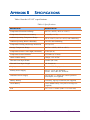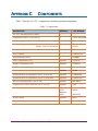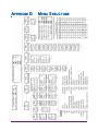
1
AT-VLT
Vision Logger
Temperature Recorder
User’s Guide
Installation Instructions and Precautions
1.
2.
3.
The appliances in the package are designed for wall mounting or table-top installation.
When mounting the product on a wall, be sure to use the correct type of screw. Secure all screws to
prevent the product from falling from its mounting.
Make all the connections to the product first, and only afterwards mount the transformer on the wall.
Safety Precautions
1.
2.
3.
4.
5.
6.
Install the product in a dry environment. Prevent humid conditions and water leakage.
Protect the project and power supply from extreme temperatures. Do not install the product near
radiators or in direct sunlight.
Prevent any foreign objects from falling on the product. Prevent spillage of any liquids, such as
strong acids.
Connect the power supply to the appropriate voltage, as marked on the unit.
In order to prevent damage to cables and connectors, do not disconnect cables by pulling on them.
Route all cables where they will not cause hazard and ensure that the cables are not harmed in any
way.
Warnings
1.
2.
3.
Do not replace cables or connectors with non-original parts.
Fault connections may cause electrocution.
The power supply is designed for indoor use only.
TABLE OF CONTENTS
Chapter 1
Introduction .........................................................1
Features..........................................................................................1
Description .....................................................................................2
Chapter 2
Installation.............................................................4
Package Contents............................................................................4
Installation Options.........................................................................5
Bracket Mounting ....................................................................5
Connections....................................................................................6
Mandatory Connections and Startup.........................................6
Optional Connections...............................................................7
Viewing Information on an External PC ...................................7
Power .............................................................................................8
Power Source ..........................................................................8
Battery Installation and Replacement .......................................9
Chapter 3
Operation.............................................................10
Displaying Temperatures...............................................................10
Printing.........................................................................................11
Advancing and Changing Printer Paper..........................................11
Alarms..........................................................................................12
Chapter 4
Configuration ......................................................14
Online Help ..................................................................................15
Configuring Alarm Settings...........................................................15
Configuring the Alarm Range.................................................16
Configuring the Alarm Delay .................................................16
Vision Recorder
i
Configuring the Alarm Output ................................................16
Configuring the End of Paper Alarm ......................................17
Configuring Print Settings .............................................................18
Configuring Temperature and Date Formats...................................19
Changing the Time and Date .........................................................20
Changing the Password .................................................................20
Changing the Device ID ................................................................21
Changing the Temperature Calibration...........................................22
Erasing the Log.............................................................................22
Changing the Sampling Rate .........................................................22
Chapter 5
Troubleshooting ..................................................23
Appendix A Factory Default Settings .....................................24
Appendix B Specifications.......................................................26
Appendix C Components.........................................................27
Appendix D Menu Structure ...................................................28
ii
Vision Recorder
CHAPTER 1
INTRODUCTION
The Vision Logger Temperature Recorder (AT-AT-VLT) records, saves, and prints
up to 290 temperature readings at predefined intervals. The AT-VLT produces an
alarm whenever the temperature goes above or below a defined range. The alarm
can be produced immediately when the temperature goes out of the defined range,
or after the temperature remains out of range for a certain period of time. The ATVLT provides several printing options, including the ability to send data to an
external PC. The AT-VLT can also send alarms to an external device via a relay
contact.
The AT-VLT can monitor, log, and print temperatures of -40°C to +130°C
(-40°F to +266°F), +\- 1°.
FEATURES
Table 1 describes the AT-VLT features, with references to the section and page in this
manual describing how to use or configure the feature.
Table 1: Vision Logger Temperature Recorder Features
FEATURE
FOR FURTHER INFORMATION SEE
Records temperatures at intervals of between one and 90
minutes
Changing the Sampling Rate on
page 22
Produces an alarm if the temperature goes above or
below a predefined range
Configuring the Alarm Range on
page 16
Records and displays temperatures in either Celsius or
Fahrenheit, and date in European or English (American)
format
Configuring Temperature and Date
Formats on page 19
Records and prints 290 readings on request at any time
Printing on page 11
Three printing formats, including graphic or text, and ID
number, time, temperature, and alarm status
Configuring Print Settings on page 18
Audio and visual alarms, including an option for sending
alarms to an external device
Alarms on page 12 and Optional
Connections on page 7
Option to export data to external PC
Viewing Information on an External
PC on page 7
Optional backup battery for up to 60 hours
Battery Installation and Replacement
on page 9
Vision Recorder
1
DESCRIPTION
Figure 1 shows the front and top of the AT-VLT.
Figure 1: Vision Logger Temperature Recorder - Front/Top View
1.
2.
3.
4.
5.
6.
7.
8.
9.
Power switch
RS-232 port
12V power jack
Buzzer silent contacts
Temperature sensor input jack
Remote alarm contacts
Paper cover clip
Secure to the bracket
Paper cover
2
Vision Recorder
Figure 2 shows the rear and bottom of the AT-VLT.
Figure 2: Vision Logger Temperature Recorder - Rear View
10.
11.
12.
13.
14.
15.
Secure tie hole
Hanging hole
Bracket hanging hole
Batteries cover
Bracket mounting
Buzzer alarm grill
Figure 3 shows the display area of the AT-VLT.
Figure 3: Vision Logger Temperature Recorder - Display Area
Vision Recorder
3
CHAPTER 2
INSTALLATION
This chapter explains how to install the AT-VLT, and includes the following topics:
▲
▲
▲
▲
Package Contents – Lists the contents of the AT-VLT package.
Installation Options – Describes the possible ways to install the AT-VLT, and
describes how to attach the AT-VLT to a wall bracket.
Connections – Describes the mandatory and optional cable connections,
including instructions on how to start the AT-VLT.
Power – Describes the AT-VLT’s power requirements and backup battery
operation capability, and explains how to install or replace batteries.
PACKAGE CONTENTS
The AT-VLT package should include the following components:
Table 2: Package Contents
DESCRIPTION
QUANTITY
PART NUMBER
AT-VLT unit with one temperature channel
1
AT-VLT (115V),
AT-VLT220 (220V Europe)
AT-VLT12 (to vehicle)
Waterproof, remote 33 feet temperature sensor
cord (10 meters)
1
AT-VLTSENSOR
Thermal paper roll, 2 inches wide, 131 feet long
(40 meters)
2 (1 installed)
VLPAPER
12V AC/DC power adaptor - US (120V) OR
1
VL115
12V AC/DC power adaptor - EU (230V)
VL220 (Europe)
# AT-VLT12 has DC cord instead of power adaptor
CRCPW
3.6V Lithium battery (CR2032)
1 (installed)
VLBAT
Hanging bracket
1
VLBRKT
User’s Guide
1
VLMANUAL
Bracket mounting screws
3
Bracket securing screw
1
4
Vision Recorder
INSTALLATION OPTIONS
You can use the AT-VLT as a standalone unit or attach it to a wall. There are two ways
to attach the AT-VLT to a wall:
▲
▲
Direct Mounting – Attach the AT-VLT directly to the wall.
Bracket Mounting – Attach the AT-VLT bracket to the wall, and hang the AT-VLT on
the bracket, as described below.
Bracket Mounting
To attach the AT-VLT to the wall using the bracket:
1. Mount the AT-VLT bracket to the wall with three screws, as shown in Figure 4.
Hooks
Figure 4: Bracket Mounting
Note:
Make sure to leave enough space on the left to operate the main switch
and connect all the other cables mentioned in Connections on page 6.
2. Hang the AT-VLT on the two mounted bracket hooks, as shown in Figure 4.
3. Open the paper cover by pushing the two cover clips (item 7 in Figure 1) to the
inside and pulling the cover out.
4. Fasten one screw through the hole under the paper roll to secure the AT-VLT to the
bracket, as shown in Figure 5.
5. Return the paper cover to its place.
Vision Recorder
5
Figure 5: Securing the Unit to the Bracket
CONNECTIONS
This section describes the cables you must connect in order to use the AT-VLT, as well
as cables you can attach in order to use optional features.
Mandatory Connections and Startup
To connect and start up the AT-VLT:
1. Plug the AC adaptor into the power supply and connect the 12V power cord to
the power jack (item 3 in Figure 6).
2. Connect the temperature sensor cord to the temperature sensor input jack (item 5
in Figure 6).
3. Switch the power switch to the On position (item 1 in Figure 6). The Power and
Sensor LEDs turn green. After a few moments, the temperature should appear in
the display area.
Figure 6: Connections
6
Vision Recorder
Optional Connections
You can connect the following optional cables:
▲
▲
▲
To send alarms to a remote device, attach a cable to the remote alarm contacts
(item 6 in Figure 6). The remote alarm contacts are a pair of ¼” terminals,
1 Amps, 12V.
To export temperature data to a PC, attach an RS-232 cable from the PC to the
RS-232 port (item 2 in Figure 6).
To silence the alarm, connect a remote buzzer silencing device by attaching a
cable with a momentary switch to momentarily short the buzzer silencer
contacts (item 4 in Figure 6). The buzzer silencer contacts are a pair of ¼”
terminals.
Viewing Information on an External PC
Before you can view information from the AT-VLT on an external PC, you must
establish a new Hyper Terminal connection on the PC.
Note:
If you have already established a Hyper Terminal connection on your PC,
skip to Viewing Information on an External PC on page 8.
Establishing a New Hyper Terminal Connection
To establish a new Hyper Terminal connection on your PC:
1. Connect an RS-232 cable from the PC to the RS-232 port (item 2 in Figure 6).
2. On the PC, open Hyper Terminal. To open Hyper Terminal, select
Start>Programs>Accessories>Communications>HyperTerminal and
double-click HYPERTRM.EXE.
Note:
If Hyper Terminal is not installed on your computer, you can install it
from the Control Panel. Double-click Add/Remove Programs, click the
Windows Setup tab, select Communications, click Details, select
Hyper Terminal, click OK, then click OK again.
3. Enter a name for the AT-VLT connection.
4. Select an icon and click OK.
5. In the Connect to window, go to the lower Connect using: menu and select
Direct to Com1 (making sure to choose a free Com port).
Vision Recorder
7
6. Click OK. If the Com port is not free, choose another port by selecting File>
Properties> and selecting the corresponding COM port, and then click OK.
Note:
Configure the COM properties as follow: Bits per second - 9600; Data
bits - 8; Parity - None; Stop bits - 1; Flow control - None,
Viewing Information on an External PC
To view information from the AT-VLT on an external PC:
1. Connect an RS-232 cable from the PC to the RS-232 port (item 2 in Figure 6).
2. On the PC, open the AT-VLT Hyper Terminal connection program. To open it,
select Start> Programs> Accessories> Communications> HyperTerminal
and double-click the AT-VLT Hyper Terminal icon that you previously created
(refer to Establishing a New Hyper Terminal Connection on page 7).
The AT-VLT Hyper Terminal window on the PC displays message lines according to
the sampling rate. The Hyper Terminal displays whatever information the AT-VLT
prints, both manually and automatically. For information on printing manually,
refer to Printing on page 11. For information on printing automatically, refer to
Configuring Print Settings on page 18.
Notes:
To capture lines one after the other, select File> Properties and select the
Setting tab. Under ASCII Setup, select Append line feed to incoming
line ends.
To capture the data to a file, select Transfer> Capture Text. Enter the
file name and click Start.
When the print format is configured as graph, only the current temperature
and the alarm range appear in Hyper Terminal. On every 12th row, the data
is displayed in full text format.
POWER
This section explains the AT-VLT’s power requirements and backup battery operation
capability, and explains how to install or replace batteries.
Power Source
The AT-VLT uses a 12V AC/DC power supply. When the AT-VLT is using the main
power supply, the Power LED is lit green.
8
Vision Recorder
In the event of a power failure, or if the working environment temperature goes
over 150°F (65°C), the AT-VLT automatically switches over to a 9V backup battery (if
installed). When operating in backup mode, the AT-VLT logs temperature
measurements to memory, but does not print. The Power LED blinks, and the
display area shows the current temperature every 30 sec. for two seconds. You can
also display the current temperature for two seconds at a time manually by pressing
. With a new 9V battery, the AT-VLT can operate in backup mode for 60 hours.
When the main power returns, the Power LED goes on without blinking, and the
printer prints the temperature measurements that were recorded but not printed
when the AT-VLT was operating in backup mode.
Battery Installation and Replacement
The AT-VLT uses two batteries:
▲
▲
Lithium battery (CR2032) – Used for saving logging data and configuration
settings, and for running the real-time clock. After replacing the Lithium
battery, you should check and reset the AT-VLT configuration settings.
9V alkaline backup battery – Used for backup operation (refer to Power
Source on page 8). This battery is optional, and is not included with the AT-VLT
package. When the Low Batt LED blinks, you should replace the 9V backup
battery.
To change or install batteries:
1. Push and slide the cover of the battery compartment out, as shown in Figure 7.
2. Install the batteries as indicated, according to the polarity marks in the battery
compartment.
3. Position the cover over the battery compartment and snap it back into place.
Figure 7: Battery Installation and Replacement
Vision Recorder
9
CHAPTER 3
OPERATION
This chapter explains how to operate the AT-VLT, and includes the following topics:
▲
▲
▲
▲
Displaying Temperatures
Printing
Advancing and Changing Printer Paper
Alarms
DISPLAYING TEMPERATURES
When the AT-VLT is on, it displays the current temperature. You can also display the
maximum and minimum measured temperatures in the AT-VLT’s memory by pressing
and
. The AT-VLT’s memory can store up to 290 readings. The time period
this covers depends on the sampling rate. For example, if the sampling rate is
15 minutes, the AT-VLT’s internal memory contains the temperature data from the last
three days.
▲
▲
Press
to display the lowest temperature in memory. Press
again to
display the highest temperature in memory, AdJ (for adjusting parameters),
and to return to the current temperature. After three seconds, the display
automatically returns to the current temperature.
Press
to display AdJ (for adjusting parameters). Press
again to
display the highest temperature in memory, the lowest temperature in memory,
and to return to the current temperature. After three seconds, the display
automatically returns to the current temperature.
Note:
You can configure the AT-VLT to display temperatures in either Celsius or
Fahrenheit. Refer to Configuring Temperature and Date Formats on
page 19.
10
Vision Recorder
PRINTING
The AT-VLT can be configured to print temperatures automatically at defined intervals.
For a description of the available print modes and instructions on configuring the
print settings, refer to Configuring Print Settings on page 18.
In addition, you can manually print the memory report (a list of all saved
measurements) on demand, or send the report to a PC to view and save the
information. To send the memory report to the printer or a PC, press
. SEnd
appears in the display area.
▲
▲
▲
To print the memory report, press
.
To send the memory report to a PC, press
.
If you do not press either button within three seconds, the display automatically
returns to the current temperature.
The AT-VLT prints or sends the memory report in whichever print mode is currently
configured. If the AT-VLT is also configured to print or send measurements
automatically, then when the printing is finished, the AT-VLT prints or sends all
measurements that were recorded during the on demand memory report printing or
sending operation.
Every report that is printed or sent on demand begins with the message MEMORY
REPORT and ends with the message END OF REPORT. The printed or sent on
demand report displays the measurements in reverse order (i.e., current
measurements are displayed before the earlier measurements).
To manually stop printing or sending a report on demand, press
. The printout
or sent report displays the message MEMORY REPORT STOPPED BY USER.
Note:
When you send a report to a PC, all data is sent within ten seconds.
ADVANCING AND CHANGING PRINTER PAPER
The AT-VLT uses thermal printing paper to print temperature readings. This type of
paper uses heat, rather than ink, to print. The AT-VLT’s printer does not print on
ordinary paper. When ordering replacement paper rolls, make sure to order thermal
paper.
Vision Recorder
11
When a red mark appears on the side of the paper, this indicates that the paper roll
is almost finished. You should replace the paper roll before it reaches the end, so
that the printer paper will not stop or get stuck.
To replace the paper roll:
1. Press
Note:
two or three times to advance the paper.
The
button does not work unless the printer is set for automatic
printing. Refer to Configuring Print Settings on page 18.
2. Tear out the latest printed report.
3. Open the paper cover and remove the leftover paper roll. The alarm buzzer will
sound, and the Out of Paper LED will blink.
4. Straighten the edge of the new paper roll with a scissors.
5. Place the new paper roll in the paper compartment, or inside the open paper
cover, and push the edge of the paper straight through the printer under the
printer’s black rubber roller.
6. Press
to advance the paper through the printer. After installing the new
roll, the alarm buzzer and the Out of Paper LED should go off.
ALARMS
The AT-VLT has the following alarm indicators:
▲
Buzzer – Some alarms trigger an internal buzzer. You can silence the buzzer
by pressing
or on the optional remote buzzer-silencer switch. Refer to
Optional Connections on page 7.You can also configure the AT-VLT so that the
buzzer does not go on. Refer to Configuring the Alarm Output on page 16.
Note:
The buzzer silencer only shuts off the internal buzzer sounds. The alarm
LEDs and the external device connected to the relay contact (if enabled)
remain operational.
▲
LEDs – The four LEDs to the left of the display area indicate various alarms,
as described below. The top LED indicates that the AT-VLT’s power is on.
▲
Relay Contact to External Device – You can connect the external device to
the AT-VLT remote alarm contacts (item 6 in Figure 6 on page 6) and configure
the AT-VLT to send alarms to the external device via a normally open relay
contact. Refer to Configuring the Alarm Output on page 16.
12
Vision Recorder
The following events trigger an alarm:
▲
▲
▲
Disconnected Temperature Sensor – If the temperature sensor is
disconnected from the AT-VLT, the display area shows the message nOS, the
Alarm LED lights, and the internal buzzer sounds (if enabled).
Alarm Range – If the measured temperature goes outside the maximum or
minimum defined temperature range for a consecutive period of time equal to
the defined alarm delay period (if any), an alarm is sent. The internal buzzer
sounds (if enabled), and an alarm is sent to an external device via the relay
contact (if enabled). In addition, the Alarm LED lights. For instructions on
configuring the buzzer and relay contact to respond to Alarm Range alarms,
refer to Configuring the Alarm Output on page 16.
End of Paper – If the printer paper runs out, the internal buzzer sounds (if
enabled), and an alarm is sent to an external device via the relay contact (if
enabled). In addition, the Out of Paper LED lights. For instructions on
configuring the buzzer and relay contact to respond to Out of Paper alarms,
refer to Configuring the End of Paper Alarm on page 17.
Figure 8 provides a close-up of the rear panel, including the remote alarm contacts
on the right side and the remote buzzer silencing device contacts on the left side.
Buzzer silencing
contacts
Figure 8: Rear Panel Close-Up
Vision Recorder
13
Remote alarm
contacts
CHAPTER 4
CONFIGURATION
This chapter explains how to configure the AT-VLT. To configure AT-VLT parameters,
you must enter a password. The default password is
. For
instructions on changing your password, refer to Changing the Password on
page 20.
To change the AT-VLT configuration:
1. Press
or
until AdJ appears in the display area.
2. Press
. PASS appears in the display area.
3. Enter your password. ALr appears in the display area. ALr allows you to
change the alarm settings.
4. The AT-VLT has nine root menu items. To scroll through the root menu items, press
. To scroll through the root menu items in reverse order, press
. The
following are the root menu items:
Ñ
ALr – Alarm configuration
Ñ
Prn – Printing configuration
Ñ
SCAL –Temperature units and date format configuration
Ñ
CLoC – Date and time configuration
Ñ
ChPA – Change password
Ñ
SIdn – ID number configuration
Ñ
CALb – Temperature calibration
Ñ
Lo9r – Erasing the logging measurements from the memory
Ñ
SAPr – Sampling rate configuration
Note:
For a full diagram of the AT-VLT menu tree, refer to Appendix D, Menu
Structure on page 28. For a list of the default factory settings, refer to
Appendix A, Factory Default Settings on page 24.
5. When you reach the root menu item that you want, press
sub-menu item appears.
6. When you have finished configuring an item, you must press
configuration changes.
14
. The first
to save the
Vision Recorder
ONLINE HELP
The AT-VLT offers online help that explains the short format display massages and
guides you through the menu configurations.
1. Open the paper cover to best view the printed online help messages.
2. If you want help on any menu item, press
. The AT-VLT will print and/or
send the online help message in whichever format is currently configured
(as described in Configuring Print Settings on page 18).
Note:
The
key can be used to access the online help in all situations, except
while the current temperature is being displayed.
3. The AT-VLT prints and/or sends a blank line after every online help message.
Notes:
You cannot print online help unless the printer is set for automatic
printing. Refer to Configuring Print Settings on page 18.
If the AT-VLT is configured to send output to an external PC, help messages
will also be sent to the external PC.
CONFIGURING ALARM SETTINGS
To configure alarm settings, display the ALr root menu. From the ALr root menu,
you can configure the following alarm settings:
▲
▲
▲
▲
Alarm Range Set (ALS) – Allows you to define a temperature range. When
the current temperature is outside of this range, the AT-VLT sends an alarm.
Alarm Delay (ALdl) – Allows you to define an alarm delay. If the current
temperature goes out of the defined temperature range, the AT-VLT does not send
an alarm until the temperature remains outside of the range for the length of
time defined by the Alarm Delay parameter.
Alarm Output (ALO) – Allows you to define whether or not the AT-VLT’s
internal alarm sounds when an alarm is sent, and whether or not alarms are sent
to an external device.
End of Paper Alarm (EOFP) – Allows you to define whether or not the
AT-VLT’s internal alarm sounds, and whether or not alarms are sent to an external
device, when the paper runs out.
Vision Recorder
15
Configuring the Alarm Range
To configure the high and low temperatures that will trigger an alarm:
1. From the ALr menu, press
. ALS appears.
2. Press
. LoA1 appears. Press
or
to set the minimum temperature.
Temperatures below this temperature will trigger an alarm.
3. Press
. HIA1 appears. Press
or
to set the maximum temperature.
Temperatures above this temperature will trigger an alarm.
4. Press
. The changes are saved and ALS appears.
Ñ
To change other alarm settings, press
alarm menu items.
or
to display the other
Ñ
To go to another root menu item, press
to display the other root menu items.
Ñ
To exit configuration and display the current temperature, press
twice.
again, then press
or
Configuring the Alarm Delay
To configure the alarm delay:
1. From the ALr menu, press
. ALS appears.
2. Press
. ALdl appears.
3. Press
. The current alarm delay setting appears.
or
to scroll among the possible alarm delay values: n0 (no
4. Press
delay), 10 (minutes), 30 (minutes), 1 h (1 hour), and 2 h (2 hours). When the
value you want to select appears, press
. ALdl appears.
5. Press
. The changes are saved and ALr appears.
6. Press
again to exit configuration and display the current temperature.
Configuring the Alarm Output
To configure the alarm output:
1. From the ALr menu, press
2. Press
or
. ALS appears.
twice. ALO appears.
16
Vision Recorder
3. Press
. The current alarm buzzer setting appears:
Ñ
buOn – The internal buzzer will sound when there is an alarm.
Ñ
buOF – The internal buzzer will not sound when there is an alarm.
. To change the setting, press
or
4. To keep the current setting, press
to toggle the setting, then press
. The current external Normally Open
contact device setting appears:
Ñ
CoOn – The external Normally Open contact is closed and a signal is
sent to the external device when there is an alarm.
Ñ
CoOF – A signal is not sent to the external device when there is an
alarm.
5. To keep the current setting, press
. To change the setting, press
to toggle the setting, then press
. ALO appears.
or
6. Press
. The changes are saved and ALr appears.
7. Press
again to exit configuration and display the current temperature.
Configuring the End of Paper Alarm
To configure the End of Paper alarm output:
1. From the ALr menu, press
. ALS appears.
2. Press
. EOFP appears.
3. Press
. The current End of Paper alarm buzzer setting appears:
Ñ
buOn – The internal alarm sounds when the printer is out of paper.
Ñ
buOF – The internal alarm does not sound when the printer is out of
paper.
4. To keep the current setting, press
. To change the setting, press the
or
button to toggle the setting, then press
. The current End of Paper
external device setting appears:
Ñ
CoOn – An alarm is sent to the external device when the printer is out of
paper.
Ñ
CoOF – An alarm is not sent to the external device when the printer is
out of paper.
5. To keep the current setting, press
. To change the setting, press
to toggle the setting, then press
. EOFP appears.
or
6. Press
. The changes are saved and ALr appears.
7. Press
again to exit configuration and display the current temperature.
Vision Recorder
17
CONFIGURING PRINT SETTINGS
To configure print settings, display the Prn root menu. From the Prn root menu,
you can configure the following print settings:
▲
▲
▲
Print Format – Allows you to choose from among three print formats. Both
the AT-VLT printer output and the external PC output will use the selected format.
Printer – Allows you to define whether or not the AT-VLT automatically prints
temperature readings. When the printer is set to print automatically, the AT-VLT
prints each temperature reading that it measures, at the defined measurement
intervals. Refer to Changing the Sampling Rate on page 22.
PC Output – Allows you to define whether or not the AT-VLT sends temperature
readings to an external PC.
To configure print settings:
1. From the Prn menu, press
Ñ
. The current print format appears:
LChr – The AT-VLT prints and sends output to an external PC using a large
character format. Each temperature record includes the following
information: Date, time, and temperature. The following is an example of
a temperature record in large character format:
29 15:32 78.0F AL
In this example, the date is the 29th of the current month, the time is
15:32 (3:32 p.m.), the temperature is 78.0°F, and the alarm is activated.
Ñ
SChr – The AT-VLT prints and sends output to an external PC using a small
character format. Each temperature record includes the following
information: ID of the unit recording the measurement, time, date, and
temperature. The following is an example of a temperature record in
small character format:
SUPCO 12345 04/29/04 15:32 78.0F A
In this example, the ID of the AT-VLT unit is SUPCO 12345 (refer to
Changing the Device ID on page 21), the date is April 29, 2004 (refer to
Changing the Time and Date on page 20), the time is 15:32 (3:32 p.m.),
and the temperature is 78.0°F, and the alarm is activated.
Ñ
9rAP – The AT-VLT prints in a graph format. The graph format prints
temperature measurements in the form of a curved graph. Every
temperature value is printed next to the relevant graph point. The
minimum and maximum temperature thresholds are shown as separate
striped lines, and the temperature range values are printed in text every
12th row. If temperature range alarms are enabled, the letter A appears
18
Vision Recorder
next to any line in which the temperature is outside of the defined
temperature range and the delay time has elapsed. In every 12th row, full
information is printed in small character format.
Note:
When information is printed to an external PC in graph format, the current
temperature and the alarm range are printed, but the graph itself is not
printed.
2. To keep the current setting, press
. To change the setting, press
or
to toggle the setting, then press
. The current printer setting appears:
Ñ
PrOn – The AT-VLT printer prints temperature records automatically at the
defined measurement intervals.
Ñ
PrOF – The AT-VLT printer does not print temperature records unless you
request a printout manually. Refer to Printing on page 11.
3. To keep the current setting, press
. To change the setting, press
or
to toggle the setting, then press
. The current PC output setting
appears:
Ñ
PCOn – The AT-VLT sends temperature records to an external PC
automatically at the defined measurement intervals.
Ñ
PCOF – The AT-VLT printer does not send temperature records unless you
request it to send output manually. Refer to Printing on page 11.
4. To keep the current setting, press
. To change the setting, press
to toggle the setting, then press
. Prn appears.
or
5. Press
to save your changes, exit configuration, and display the current
temperature.
CONFIGURING TEMPERATURE AND DATE FORMATS
To configure the format in which the AT-VLT displays temperatures (Celsius or
Fahrenheit) and dates (European or American):
1. Display the SCAL root menu.
2. From the SCAL menu, press
Ñ
F d9 – Fahrenheit
Ñ
C d9 – Celsius
. The current temperature format appears:
3. To keep the current setting, press
. To change the setting, press
or
to toggle the setting, then press
. The current date format appears:
Ñ
EndA – English (American) date format (mm/dd/yy)
Ñ
EudA – European date format (dd/mm/yy)
Vision Recorder
19
4. To keep the current setting, press
. To change the setting, press
to toggle the setting, then press
. SCAL appears.
or
5. Press
to save your changes, exit configuration, and display the current
temperature.
CHANGING THE TIME AND DATE
To change the time and date:
1. Display the CLoC root menu.
2. From the CLoC menu, press
Note:
. SdAY appears.
To keep the current date and change the time, press
or
to toggle
the setting to Shr, then follow the instructions starting at number 4.
3. To change the date, press
. The current month appears in numerical format
(01 = January, 02 = February, etc.). Press
or
to change the setting,
then press
. The current day of the month appears. Press
or
to
change the setting, then press
. The last two numbers of the year appears.
Press
or
to change the setting, then press
. Shr appears.
4. To change the time, press
when Shr is displayed. The current hour
appears. Press
or
to change the setting, then press
. The current
time in minutes appears. Press
or
to change the setting, then press
. CLoC appears.
5. Press
to save your changes, exit configuration, and display the current
temperature.
CHANGING THE PASSWORD
To change the AT-VLT password:
1. Display the ChPA root menu.
2. From the ChPA menu, press
. PASS appears.
3. Enter a sequence of four keys. PASS appears again.
4. Enter the same sequence of four keys to confirm the password. If the second
sequence is the same as the first sequence, ChPA appears. If it is not, PASS
appears again, and you must repeat steps three and four.
5. Press
to save the new password, exit configuration, and display the current
temperature.
20
Vision Recorder
CHANGING THE DEVICE ID
The AT-VLT has a device ID that appears in temperature reports. The purpose of the
device ID is to identify the device producing printouts and reports when printouts
and reports are being collected from more than one device.
The device ID consists of 11 alphanumeric characters. You can change each
character individually by entering a numerical code of one or two numbers. Table 3
shows the code for setting the device ID.
Table 3: Numerical Code for Setting Device ID
CHR.
CODE
CHR.
CODE
CHR.
CODE
CHR.
CODE
CHR.
CODE
0
0
8
8
F
16
N
24
V
32
1
1
9
9
G
17
O
25
W
33
2
2
10
H
18
P
26
X
34
3
3
A
11
I
19
Q
27
Y
35
4
4
B
12
J
20
R
28
Z
36
5
5
C
13
K
21
S
29
-
37
6
6
D
14
L
22
T
30
7
7
E
15
M
23
U
31
To change the device ID:
1. Display the SIdn root menu.
2. Press
. The number 1 appears, followed by a space and a code for the first
ID character that will appear in the device. Press
or
to change the
character, according to the code in Table 3.
3. Press
to move on to the next character. Repeat this procedure for each
character.
4. When you are finished, press
5. Press
Vision Recorder
to save your changes. SIdn appears.
again to exit configuration and display the current temperature.
21
CHANGING THE TEMPERATURE CALIBRATION
To change the temperature calibration:
1. Display the CALb root menu.
2. Press
. The number 0.0 appears.
3. Press
or
to raise or lower the temperature measurement, in steps of
0.1°. You can raise or lower the measurement by -2° to 2° in one action.
4. When you are finished, press
. CALb appears.
5. Press
to save your changes, exit configuration, and display the current
temperature.
ERASING THE LOG
The AT-VLT saves the last temperature measurements (up to 290 logs). To erase the
log:
1. Display the Lo9r root menu.
2. Press
. The log is erased, and ALr appears.
3. The AT-VLT will print and or send the message MEMORY RESET BY USER,
<date>, < time> in the currently configured print format.
4. Press
to exit configuration and display the current temperature.
CHANGING THE SAMPLING RATE
The AT-VLT measures temperatures at defined intervals. To change the intervals at
which temperatures are measured:
1. Display the SAPr root menu.
2. Press
. The current sampling rate appears. The sampling rate can be any
value between 1 and 90 minutes.
3. Press
or
to change the sampling rate. When you are finished, press
. SAPr appears.
4. Press
to save your changes, exit configuration, and display the current
temperature.
22
Vision Recorder
CHAPTER 5
TROUBLESHOOTING
Table 4 lists common problems and suggested solutions.
Table 4: Troubleshooting
PROBLEM
SUGGESTED SOLUTIONS
No power
Wait five seconds after switching on the power switch.
Poor or no printing
· Make sure you are using thermal printing paper. The AT-VLT
will not print on non-thermal paper.
· Replace the printing side of the thermal paper, or replace the
thermal paper itself.
· Move the AT-VLT to a location with a temperature between 0 to
149°F (-18 to 65°C).
Wrong time or date
· Change the time or date. Refer to Changing the Time and
Date on page 23.
· Make sure you are using the correct date format (dd/mm/yy or
mm/dd/yy). Refer to Configuring Temperature and Date
Formats on page 19.
· Replace the Lithium battery (CR2032). Refer to Battery
Installation and Replacement on page 9.
Cannot print online help
Vision Recorder
Change the print mode to PrOn. Refer to Printing on page 11.
23
APPENDIX A FACTORY DEFAULT SETTINGS
To restore the Vision Recorder to its factory default settings:
1. Switch the power switch off.
2. Switch the power switch back on while pressing
3. When FAdF appears in the display area, press
Note:
.
.
Restoring factory settings does not delete the temperature logs.
Table 5 lists the factory default settings.
Table 5: Factory Default Settings
MENU ITEM
PARAMETER
DEFAULTS
LEGAL VALUES
PASSWORD SETTINGS
PASS
Password
ALARM SETTINGS (AL.)
ALS
Alarm Range Settings
Min: -4°F (-20°C)
Max: 86°F (30°C)
-67°F to 302°F
(-55°C to 150°C)
ALdl
Alarm Delay
No
No, 15, 30 min, 1, 2 hr
ALO
Alarm Output
BuOn (buzzer On)
CoOn (contact On)
buOn/buOF
CoOn/CoOF
EOP
End of Paper
BuOn (buzzer On)
CoOn (contact On)
buOn/buOF
CoOn/CoOF
PRINT SETTINGS (PRN)
Print Format
SChr (small character)
LChr (large), SChr
(small), 9rAP (graph)
Printer On/Off
PrOn (Printer On)
PrOn, PrOF
PC Output On/Off
PCOn (PC Output On)
PCOn, PCOF
24
Vision Recorder
MENU ITEM
PARAMETER
DEFAULTS
LEGAL VALUES
TEMPERATURE AND DATE FORMATS (SCAL)
# AT-VLT
# AT-VLT220
Temperature
Format
F d9
(Fahrenheit)
C d9 (Celsius)
C d9 (Celsius),
F d9 (Fahrenheit)
Date Format
EndA, English,
(mm/dd/yy)
EudA, Europe,
(dd/mm/yy)
EudA (dd/mm/yy),
EndA (mm/dd/yy)
CURRENT DATE AND TIME (CLOC)
# AT-VLT
# AT-VLT220
SdAY
Date
12/31/04
31/12/04
Shr
Time
12:00
12:00
DEVICE ID NUMBER (SIDN)
SIdn
Device ID Number
SUPCO 12345
TEMPERATURE CALIBRATION (CALB)
CALb
Temperature
Calibration
SAPr
Sampling Rate
0°
–2° to 2°
SAMPLING R ATE (SAPR)
Vision Recorder
10 min
1 to 90 minutes
25
APPENDIX B
SPECIFICATIONS
Table 6 lists the AT-VLT’s specifications.
Table 6: Specifications
DESCRIPTION
SPECIFICATION
Temperature Measurement Range
-40°F to +266°F (-40°C to +130°C)
Temperature Measurement Accuracy
+/- 1.8°F (+/- 1°C)
Ambient Operating Temperature Range
0°F to +150°F (-18°C to +65°C) non-condensing
Ambient Operating Relative Humidity
0 to 95% non-condensing
Temperature Writing and Storage Resolution
0.2°F (0.1°C)
Storage Temperature Range
-40°F to +150°F (-40°C to +65°C)
Temperature Sensor Cord Length (extensible)
33 feet (10 m)
Temperature Sensor Diameter
0.25 inches (6.35 mm)
Alarm Contact Rating
1 Amps, 12V AC/DC
Thermal Chart Paper Width
2 inches (50.8 cm)
Thermal Chart Paper Length
131 feet (40 m)
Display
Numeric LED Display, 4 characters
Primary Power Supply
VL115: 115 V AC, 50/60 Hz
VL220: 220~240V AC, 50/60 Hz
Alternative Power Supply
12V AC/DC, 1.5 Amps (for vehicle operation
with adapter, not supplied)
Battery Backup
9V battery, logs up to 50 hours (not supplied)
Clock Battery
3.6V Lithium battery, two years in average use
(supplied)
Size
8.2 x 5.3 x 2.7 inches (208.6 x 135 x 69 mm)
26
Vision Recorder
APPENDIX C
COMPONENTS
Table 7 lists the AT-VLT’s components, including optional components.
Table 7: Components
DESCRIPTION
SUPPLIED
PART NUMBER
AT-VLT with temperature channel
1
Temperature Sensor, 33 feet (10 m)
1
AT-VLTSENSOR
2” thermal paper roll, 131 feet length (40 m)
2
VLPAPER
12V AC/DC, power adaptor: USA: 130V AC operation
Europe: 230V AC operation
1
VL115
VL230
3.6V Lithium battery
1
VLBAT
User’s Manual
1
VLMANUAL
Wall mounting bracket
1
VLBRKT
Paper compartment cover
Optional
VLPACO
Battery compartment cover
Optional
VLBACO
IP65 clear case and hinge, 9.8x9.8x4” (25x25x10cm)
Optional
VLWPCASE
Silencer remote kit, 16.4 feet (5m)
Optional
VLSK
Extension cable for temperature sensor, 10 feet (3m)
Optional
CABLE10H
Extension cable for temperature sensor, 33 feet (10m)
Optional
CABLE33H
RS-232 serial data cable, 6 feet (1.8m)
Optional
RSCABLE
Vehicle power reducer from 24V DC to 12V DC
Optional
VPR
Automatic telephone dialer
Optional
115V
Optional
230V
ADTA
ADTA220
Remote Alarm
Optional
RA25
DC power Cord (for vehicle Operation)
Optional
CRCPW
Vision Recorder
27
APPENDIX D
MENU STRUCTURE
28
Vision Recorder