1
Model 9307
pico-TIMING™Discriminator
Operating and Service Manual
Printed in U.S.A.
ORTEC® Part No. 764020
Manual Revision C
1202
Advanced Measurement Technology, Inc.
a/k/a/ ORTEC®, a subsidiary of AMETEK®, Inc.
WARRANTY
ORTEC* warrants that the items will be delivered free from defects in material or workmanship. ORTEC makes
no other warranties, express or implied, and specifically NO WARRANTY OF MERCHANTABILITY OR
FITNESS FOR A PARTICULAR PURPOSE.
ORTEC’s exclusive liability is limited to repairing or replacing at ORTEC’s option, items found by ORTEC to
be defective in workmanship or materials within one year from the date of delivery. ORTEC’s liability on any
claim of any kind, including negligence, loss, or damages arising out of, connected with, or from the performance
or breach thereof, or from the manufacture, sale, delivery, resale, repair, or use of any item or services covered
by this agreement or purchase order, shall in no case exceed the price allocable to the item or service furnished
or any part thereof that gives rise to the claim. In the event ORTEC fails to manufacture or deliver items called
for in this agreement or purchase order, ORTEC’s exclusive liability and buyer’s exclusive remedy shall be release
of the buyer from the obligation to pay the purchase price. In no event shall ORTEC be liable for special or
consequential damages.
Quality Control
Before being approved for shipment, each ORTEC instrument must pass a stringent set of quality control tests
designed to expose any flaws in materials or workmanship. Permanent records of these tests are maintained for
use in warranty repair and as a source of statistical information for design improvements.
Repair Service
If it becomes necessary to return this instrument for repair, it is essential that Customer Services be contacted in
advance of its return so that a Return Authorization Number can be assigned to the unit. Also, ORTEC must be
informed, either in writing, by telephone [(865) 482-4411] or by facsimile transmission [(865) 483-2133], of the
nature of the fault of the instrument being returned and of the model, serial, and revision ("Rev" on rear panel)
numbers. Failure to do so may cause unnecessary delays in getting the unit repaired. The ORTEC standard
procedure requires that instruments returned for repair pass the same quality control tests that are used for
new-production instruments. Instruments that are returned should be packed so that they will withstand normal
transit handling and must be shipped PREPAID via Air Parcel Post or United Parcel Service to the designated
ORTEC repair center. The address label and the package should include the Return Authorization Number
assigned. Instruments being returned that are damaged in transit due to inadequate packing will be repaired at the
sender's expense, and it will be the sender's responsibility to make claim with the shipper. Instruments not in
warranty should follow the same procedure and ORTEC will provide a quotation.
Damage in Transit
Shipments should be examined immediately upon receipt for evidence of external or concealed damage. The carrier
making delivery should be notified immediately of any such damage, since the carrier is normally liable for damage
in shipment. Packing materials, waybills, and other such documentation should be preserved in order to establish
claims. After such notification to the carrier, please notify ORTEC of the circumstances so that assistance can be
provided in making damage claims and in providing replacement equipment, if necessary.
Copyright © 2002, Advanced Measurement Technology, Inc. All rights reserved.
*ORTEC® is a registered trademark of Advanced Measurement Technology, Inc. All other trademarks used
herein are the property of their respective owners.
iii
CONTENTS
WARRANTY . . . . . . . . . . . . . . . . . . . . . . . . . . . . . . . . . . . . . . . . . . . . . . . . . . . . . . . . . . . . . . . . . . . . . . . ii
SAFETY INSTRUCTIONS AND SYMBOLS . . . . . . . . . . . . . . . . . . . . . . . . . . . . . . . . . . . . . . . . . . . . . . . iv
SAFETY WARNINGS AND CLEANING INSTRUCTIONS . . . . . . . . . . . . . . . . . . . . . . . . . . . . . . . . . . . . . v
1. DESCRIPTION . . . . . . . . . . . . . . . . . . . . . . . . . . . . . . . . . . . . . . . . . . . . . . . . . . . . . . . . . . . . . . . . . . . 1
2. SPECIFICATIONS* . . . . . . . . . . . . . . . . . . . . . . . . . . . . . . . . . . . . . . . . . . . . . . . . . . . . . . . . . . . . . . .
2.1. PERFORMANCE . . . . . . . . . . . . . . . . . . . . . . . . . . . . . . . . . . . . . . . . . . . . . . . . . . . . . . . . . . . . .
2.2. CONTROLS AND INDICATORS . . . . . . . . . . . . . . . . . . . . . . . . . . . . . . . . . . . . . . . . . . . . . . . . .
2.3. INPUTS . . . . . . . . . . . . . . . . . . . . . . . . . . . . . . . . . . . . . . . . . . . . . . . . . . . . . . . . . . . . . . . . . . . .
2.4. OUTPUTS . . . . . . . . . . . . . . . . . . . . . . . . . . . . . . . . . . . . . . . . . . . . . . . . . . . . . . . . . . . . . . . . . .
2.5. ELECTRICAL AND MECHANICAL . . . . . . . . . . . . . . . . . . . . . . . . . . . . . . . . . . . . . . . . . . . . . . . .
2.6. ORDERING INFORMATION . . . . . . . . . . . . . . . . . . . . . . . . . . . . . . . . . . . . . . . . . . . . . . . . . . . .
2
2
2
2
2
3
3
3. INSTALLATION AND OPERATION . . . . . . . . . . . . . . . . . . . . . . . . . . . . . . . . . . . . . . . . . . . . . . . . . . .
3.1. GENERAL . . . . . . . . . . . . . . . . . . . . . . . . . . . . . . . . . . . . . . . . . . . . . . . . . . . . . . . . . . . . . . . . . .
3.2. CONNECTION TO POWER . . . . . . . . . . . . . . . . . . . . . . . . . . . . . . . . . . . . . . . . . . . . . . . . . . . . .
3.3. INPUT CONNECTIONS . . . . . . . . . . . . . . . . . . . . . . . . . . . . . . . . . . . . . . . . . . . . . . . . . . . . . . . .
3.4. OUTPUT CONNECTIONS . . . . . . . . . . . . . . . . . . . . . . . . . . . . . . . . . . . . . . . . . . . . . . . . . . . . . .
3.5. ADJUSTING THE INPUT SIGNAL AMPLITUDE . . . . . . . . . . . . . . . . . . . . . . . . . . . . . . . . . . . . .
3.6. THRESHOLD ADJUSTMENT . . . . . . . . . . . . . . . . . . . . . . . . . . . . . . . . . . . . . . . . . . . . . . . . . . .
3.7. ADJUSTING THE SLEWING COMPENSATION . . . . . . . . . . . . . . . . . . . . . . . . . . . . . . . . . . . . .
3.8. LIMITING THE COUNTING RATE TO AVOID SPECTRUM DISTORTION . . . . . . . . . . . . . . . . .
3.9. THE BENEFIT OF REVERSED START/STOP LOGIC . . . . . . . . . . . . . . . . . . . . . . . . . . . . . . . . .
3
3
3
4
4
5
6
6
7
7
4. MAINTENANCE AND SERVICE . . . . . . . . . . . . . . . . . . . . . . . . . . . . . . . . . . . . . . . . . . . . . . . . . . . . . . 8
iv
SAFETY INSTRUCTIONS AND SYMBOLS
This manual contains up to three levels of safety instructions that must be observed in order to avoid
personal injury and/or damage to equipment or other property. These are:
DANGER
Indicates a hazard that could result in death or serious bodily harm if the safety instruction is
not observed.
WARNING
Indicates a hazard that could result in bodily harm if the safety instruction is not observed.
CAUTION
Indicates a hazard that could result in property damage if the safety instruction is not
observed.
Please read all safety instructions carefully and make sure you understand them fully before attempting to
use this product.
In addition, the following symbol may appear on the product:
ATTENTION – Refer to Manual
DANGER – High Voltage
Please read all safety instructions carefully and make sure you understand them fully before attempting to
use this product.
v
SAFETY WARNINGS AND CLEANING INSTRUCTIONS
DANGER
Opening the cover of this instrument is likely to expose dangerous voltages. Disconnect the
instrument from all voltage sources while it is being opened.
WARNING Using this instrument in a manner not specified by the manufacturer may impair the
protection provided by the instrument.
Cleaning Instructions
To clean the instrument exterior:
! Unplug the instrument from the ac power supply.
! Remove loose dust on the outside of the instrument with a lint-free cloth.
! Remove remaining dirt with a lint-free cloth dampened in a general-purpose detergent and water
solution. Do not use abrasive cleaners.
CAUTION To prevent moisture inside of the instrument during external cleaning, use only enough liquid
to dampen the cloth or applicator.
!
Allow the instrument to dry completely before reconnecting it to the power source.
vi
1
ORTEC Model 9307 pico-TIMING
Discriminator
1. DESCRIPTION
The ORTEC Model 9307 pico-TIMING
Discriminator defines the arrival time of analog
pulses from ultra-fast detectors with picosecond
precision. Moreover, this superb performance is
delivered over an extremely wide range of pulse
heights with negligible influence of pulse amplitude
on the timing output. With the Model 9307, the
difficult task of adjusting pulse-shaping cables has
been eliminated. The internal pulse shaping in the
pico-TIMING Discriminator is optimum for singlephoton or single-ion time measurements with
microchannel plate detectors, microchannel plate
photmultiplier tubes, and fast silicon photodiodes.
The pico-TIMING Discriminator accepts analog
input pulses with amplitudes ranging from -50 mV
to -5 V, and pulse widths from 400 ps to 5 ns
FWHM. The amplitude threshold for generating a
timing output is adjustable from -25 mV to -1 V with
a 10-turn locking dial.
Ultra-fast circuits are incorporated in the picoTIMING Discriminator to minimize time slewing. As
a result, input amplitudes can vary over as much as
a 100:1 range with negligible shift in the timing
output. This ensures excellent time resolution, even
when the signal source produces a wide range of
randomly varying signal amplitudes. A front-panel
screwdriver adjustment permits fine-tuning the
slewing compensation to match the characteristics
of a particular detector. An adjacent test point
makes it easy to monitor the adjustment with a
voltmeter.
Two fast negative NIM outputs provide the flexibility
to trigger a time-to-amplitude converter (TAC) while
simultaneously driving other instruments. The 500ns-wide TTL output can be used with instruments
that require a positive logic signal, such as counters
and ratemeters. A front-panel LED flashes with
each output pulse to indicate triggering.
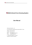
Fig. 1.1. The Fluorescence Lifetime
Instrument Response Function Recorded
with a Model 9306 1-GHz Preamplifier and
the Model 9307 pico-TIMING Discriminator.
Time resolutions from 30 to 60 ps FWHM are
possible with the system shown in Fig. 1.2.
For detectors having rise times less than 1 ns, the
ORTEC Model 9306 1-GHz Preamplifier should be
used to amplify small signals before presentation to
the input of the Model 9307 pico-TIMING
Discriminator. For rise times $1 ns, the Model
VT120 Fast-Timing Preamplifier should be
substituted for the Model 9306. The Model 9307
incorporates a compatible, 9-pin D connector on its
rear panel to supply power to either preamplifier.
2
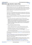
Fig. 1.2. Typical Block Diagram for Fluorescence Lifetime Spectrometer.
2. SPECIFICATIONS*
2.1. PERFORMANCE
TIME SLEWING (Walk) <±20 ps shift in the timing
output for input signal amplitudes from -150 mV to
-1.5 V. (Typically <±50 ps for signal amplitudes
from -50 mV to -5 V.) Measured using a 1-ns-wide
input pulse with 350-ps rise and fall times.
PULSE-PAIR RESOLUTION <10 ns at the fast
negative NIM outputs.
MAXIMUM INPUT/OUTPUT RATE Accepts burst
rates up to 100 MHZ.
OPERATING TEMPERATURE RANGE 0 TO
50°C.
point located next to the potentiometer facilitates
monitoring the actual setting. Test point output
impedance: 100 .
S
OUTPUT LED Front-panel LED flashes on each
output pulse to indicate active triggering.
2.3. INPUTS
INPUT Front-panel SMA connector accepts
unipolar input signals with amplitudes in the range
of -50 mV to -5 V. Minimum input pulse width: 400
ps (FWHM). Maximum input pulse width: 5 ns
(FWHM). Input impedance: 50 . The input is
protected to ±5 V.
S
2.4. OUTPUTS
THRESHOLD TEMPERATURE
<±0.1 mV/°C (0 to 50°C).
SENSITIVITY
TRANSMISSION DELAY TEMPERATURE
SENSITIVITY <±10 ps/°C (0 to 50°C.)
2.2. CONTROLS AND INDICATORS
FAST NEGATIVE NIM OUTPUTS Front-panel
BNC connectors provide two independent, fast
negative NIM output logic pulses. Output amplitude
is nominally -800 mV into a 50- load. Pulse width
is nominally 2.5 ns.
S
THRESHOLD Front-panel, 10-turn potentiometer
with locking dial allows adjustment of the input
discriminator threshold from -25 mV to -1 V.
TTL OUTPUT Front-panel BNC connector provides
a positive TTL pulse, triggered by the fast negative
NIM output. The 500-ns width of the TTL pulse is
non-updating. Output impedance: <1 , shortcircuit protected.
SLEWING COMPENSATION Front-panel, 20-turn,
screwdriver fine-tuning to minimize time slewing as
a function of input pulse amplitude. Adjustable over
a range of approximately ±30 mV. A front-panel test
PRAMP POWER Rear-panel, 9-pin D connector
provides ±12-V and ±24-V power for the ORTEC
Model 9306 1-GHz Preamplifier, the Model VT 120
S
3
fast-Timing Preamplifier, or other preamplifiers
utilizing the industry-standard preamplifier power
plug.
2.5. ELECTRICAL AND MECHANICAL
2.6. ORDERING INFORMATION
To order, specify:
Model
Description
9307
pico-TIMING™Discriminator
SMA
58-0.15
RG-58U (50- ) Coaxial Cable with SMA
Connectors, 0.15-m length
SMA
58-0.5
RG-58U (50- ) Coaxial Cable with SMA
Connectors, 0.5-m length
WEIGHT
Net 0.9 kg (2.0 lb).
Shipping 1.8 kg (4.0 lb).
SMA
58-1.5
RG-58U (50- ) Coaxial Cable with SMA
Connectors, 1.5-m length
SMA/BNC
DIMENSIONS NIM-standard single-width module,
3.43 X 22.13 cm (1.35 X 8.714 in.) Front panel per
DOE/ER-0457T.
SMA to BNC Adapter with male SMA and
female BNC
BNC/SMA
BNC to SMA Adapter with male BNC and
female SMA
POWER REQUIRED The Model 9307 derives its
power from a NIM bin/power supply, such as the
ORTEC Model 4001A/4002D. Required dc voltages
and currents are: +12 V and 35 mA, +6 V at 70 mA,
-6 V at 360 mA, and -12 V at 100 mA.
S
S
S
3. INSTALLATION AND OPERATION
3.1. GENERAL
The Model 9307 power requirements must be
furnished from a NIM-standard bin/power supply
that includes ±6-V power distribution, such as the
ORTEC 4001A/4002D, 4001C/4002D, or
4001C/4002E NIM Bins/Power Supplies.
The NIM bin/power supply in which the 9307
normally will be operated is designed for relay rack
mounting. If the equipment is rack mounted, be
sure that there is adequate ventilation to prevent
excessive localized heating in the Model 9307. The
temperature equipment mounted in racks can easily
exceed the maximum limit of 50°C unless
precautions are taken.
3.2. CONNECTION TO POWER
The power demanded by a NIM bin full of NIM
modules that incorporate high-density electronic
circuits can exceed the maximum power available
from the NIM bin power supply. Before installing the
modules in the NIM bin, add the current
requirements specified for each module, and check
that the total current required at each voltage does
not exceed the maximum output of the power
supply. Also check the total power required against
the maximum power specification for the power
supply. If the suite of modules demands excessive
power, some of the modules must be moved to a
second NIM bin/power supply.
CAUTION
Do not insert the Model 9307 in a NIM bin without
first turning off the NIM bin power. Inserting the
module in the NIM bin with power on may damage
the ultra-fast comparators in the Model 9307. The
NIM bin power should be turned on only after the
Model 9307 has been securely installed in the NIM
bin.
Before installing the Model 9307 in the NIM bin,
turn off the NIM bin power, then slide the 9307 into
a convenient slot and tighten the retaining screws at
the top and bottom of the module. The Model 9307
should be installed in the NIM bin at a location that
is close to the module that utilizes the output of the
Model 9307. After all the modules have been
mounted in the NIM bin, turn on the NIM bin power.
Using a voltmeter and the test points at the right
side of the NIM bin, check that the power supply
voltages are operating at their correct values. A
sagging power voltage indicates that the current
4
demand from the modules exceeds the limit of the
power supply, or it indicates a possible fault in the
power supply.
3.3. INPUT CONNECTIONS
For Detector Rise Times <1 ns The Model 9307
pico-TIMING Discriminator has been designed for
use with ultra-fast detectors, which have pulse rise
times as short as 350 ps. In order to obtain the best
time resolution, special care must be exercised to
preserve the fast rise time. Normally, this requires
the use of short, 50- , coaxial cables with SMA
connectors. Typically, a fast preamplifier, such as
the Model 9306 1-GHz Preamplifier, is required
between the detector and the input of the Model
9307 to increase the amplitude of the detector
output pulses (see Fig. 1.2). The total length of the
coaxial cables from the detector to the preamplifier
and from the preamplifier to the pico-TIMING
Discriminator should be kept less than 1.7 meters to
avoid degradation of the signal rise time. The
coaxial cable between the detector and the Model
9306 preamplifier also should be as short as
possible to minimize electrical interference from
neighboring instruments. The inputs of both the
Model 9306 and the Model 9307 include internal 51resistors for proper termination of the 50cable.
S
S
S
For Detector rise Times >1 ns If a detector having
an output rise time $1 ns is employed, a longer
length of 50- coaxial cable with BNC connectors
can be used between the preamplifier and the
Model 9307. See the Ordering Information at the
end of Section 2, or consult the ORTEC catalog for
the proper coaxial cables and the BNC to SMA
connector adapters. If the detector produces
negative pulses with amplitudes that cover a
substantial portion of the range from -50 mV to -5
V, the detector can be connected directly to the
input of the Model 9307. Note that the input of the
Model 9307 is protected only to ±5 V. If the detector
produces signal amplitudes beyond ±5 V, diodes
will have to be installed at the signal source to limit
the amplitude to within ±5 V. If signal amplification
is required for a detector having a rise time $1 ns,
the Model VT120 Fast-Timing Preamplifier should
be used in place of the Model 9306.
S
Preamplifier Power Connection Either the Model
9306 or the Model VT120 can derive its power from
the preamplifier power plug on the Model 9307 rear
panel.
Avoiding Ground-Loop Noise To avoid noise
induced by ground loops, the detector and
preamplifier should be isolated from any grounds in
the vicinity of the detector. The only ground
supplied to the detector and preamplifier should
come directly from the NIM bin housing the Model
9307. This can be accomplished by mounting the
detector high-voltage supply in the NIM bin next to
the Model 9307, and by relying on the high-voltage
cable, the preamplifier power cable, and the coaxial
signal cables to provide the ground to the
preamplifier and detector.
Getting the Right Input Signal Polarity The
Model 9307 input requires a negative signal
polarity. This is the normal pulse polarity provided
by the anode of a photomultiplier tube (PMT), a
microchannel plate, or a microchannel plate PMT.
For detectors which have a positive signal polarity,
a fast inverting transformer (such as the Model IT
100) or the Model VT 120B Fast-Timing
Preamplifier can be used to invert the signal.
The Proper Input Pulse Width For best timing
performance, the pulse supplied to the input of the
Model 9307 should have a width at half its
amplitude that falls in the range of 400 ps to 5 ns.
This is the typical pulse width for single-photon or
single-ion timing with micorchannel plates,
microchannel plate PMTs, and photmultiplier tubes.
The pico-TIMING Discriminator can be used with
fast scintillators on PMTs, but the resulting time
resolution will be 10% to 30% worse than can be
obtained with a conventional Constant-Fraction
Discriminator. Conversely, the Model 9307 is the
optimum solution for single-photon or single-ion
timing.
3.4. OUTPUT CONNECTIONS
There are three outputs on the Model 9307: two fast
negative NIM logic outputs, and one TTL output.
FAST NIM Outputs The two FAST NIM outputs are
intended for precise timing applications with a
Time-to-Amplitude Converter (TAC), such as the
ORTEC Models 457, 566, or 567 (see Fig. 1.2).
Each of these two outputs generates a current
pulse, which has a rise time of ~400 ps, a width of
2.5 ns, and an amplitude of approximately -16 mA.
The leading edge of the output pulse at the input to
the pico-TIMING Discriminator. The FAST NIM
cable
outputs are intended to drive a 50terminated in 50 at the remote end of the cable.
S
S
5
Thus, these two outputs produce pulses of
nominally -800-mV amplitude on a terminated 50cable. The quiescent level between pulses is
nominally 0 V. Most TACs provide the 50termination internally at their inputs. A 50- cable
with BNC connectors can be used to connect the
FAST NIM outputs to either the START or STOP
input on the TAC. Normally, the length of this cable
is not critical. When driven by a noise-free pulser
with a rise time <1 ns at the input of the Model
9307, the pico-TIMING discriminator is capable of
a time resolution <15 ps FWHM (Full Width at Half
Maximum peak height). Consequently, most of the
contribution to the time resolution comes from
timing jitter or noise in the detector connected to the
Model 9307 input.
S
S
S
TTL Output The third output provides a positive
TTL logic pulse with a width of approximately 500
ns. This output is useful for driving slower
instruments such as counters and ratemeters.
Either 50- or 93- cables with BNC connectors
can be used with the TTL output. For cable lengths
<1 meter, it is not necessary to terminate this cable
in its characteristic impedance. The TTL output can
drive either TTL inputs or Slow Positive NIM Logic
inputs. The TTL output is triggered from the FAST
NIM outputs, and it flashes the adjacent LED on
every output pulse.
S
S
3.5. ADJUSTING THE INPUT SIGNAL
AMPLITUDE
Large Pulse Amplitudes from a PMT Anode If
the amplitude of the output signal from the anode of
a photmultiplier tube is large enough to use directly
with the input to the pico-TIMING Discriminator, the
range of signal amplitudes can be selected by
adjusting the high voltage applied to the
photomultiplier tube. An oscilloscope with a 500MHZ bandwidth and a 50- input impedance is
adequate to measure the PMT pulses. The high
voltage should be increased until the signals cover
most of the 0 to -5-V operating range. The PMT
manufacturer’s instructions regarding operating
voltage and maximum anode signal should be
consulted to select the optimum voltage range, and
to avoid distortion of the signals by anode
saturation. Do not exceed the ±5-V limits on the
input to the Model 9307.
S
Amplified Pulses with >1-ns Rise Times For
single-photon counting with a photomultiplier tube,
a fast amplifier is typically needed to increase the
amplitude of the pulses from the PMT anode. An
oscilloscope with a 500-MHZ bandwidth and a 50input impedance can be used to observe the
amplified pulses. The easiest way to select the
pulse amplitude range is to adjust the high voltage
on the PMT. Consult the PMT manufacturer’s
specifications for the allowable voltage on the
photmultiplier tube. The high voltage should be
adjusted until the largest pulse amplitudes lie just
within the linear range of the amplifier output. If the
linear range of the amplifier output is exceeded, the
pulses will be distorted, and the time resolution will
be compromised. Do not exceed the ±5-V limit of
the Model 9307 input.
S
Amplified Pulses with <1-ns Rise Times For
microchannel plate PMTs, a fast preamplifier with
an output rise time of about 350 ps is typically used
to prepare the pulses for the Model 9307 input. To
observe these pulses an oscilloscope with a
bandwidth $4 GHz and a 50- input impedance is
required. The simplest method for selecting the
range of signal amplitudes is to adjust the high
voltage applied to the microchannel plate PMT.
Consult the manufacturer’s specifications regarding
the allowable range of anode voltage. If it is not
possible to adjust the anode voltage, high
bandwidth attenuators, such as the Hewlett Packard
Models HP 8494B and HP 8495B, can be inserted
between the microchannelplate PMT output and the
input to the fast preamplifier. These attenuators can
be adjusted to select the desired range of pulse
amplitudes at the preamplifier output. One of the
above two methods should be used to adjust the
gain so that the largest pulse amplitudes are just
less than the linear limit of the preamplifier output.
Do not exceed the ±5-V limit of the Model 9307
input.
S
If a 4-GHz oscilloscope is not available, the pulse
amplitude can be increased until a noticeable
distortion of the peak in the time spectrum is
observed (see section 3.7). This distortion is caused
by saturation of the pulses at the preamplifier
output. Gradually reduce the pulse amplitudes until
the distortion is eliminated.
6
3.6. THRESHOLD ADJUSTMENT
Function and Range The 10-turn locking dial on
the front panel controls the amplitude threshold for
accepting input pulses that are allowed to produce
a timing output. This threshold is adjustable over
the nominal range of -25 mV to -1.0 V. The dial
reading is moderately accurate on pulse widths near
the 5 ns FWHM limit. On pulse widths approaching
the 400 ps limit the actual threshold will be higher
than the dial indication due to bandpass limitations
in comparator circuits.
Initial Adjustment to Reject Noise The
THRESHOLD control is typically used to prevent
the Model 9307 from triggering on low-level noise
from the signal source. The simplest way to adjust
this control is to turn off the supply of photons or
ions to the detector, while leaving the detector in its
normal operating condition. Subsequently, the
THRESHOLD dial is turned counter-clockwise until
the output LED glows brightly. Under this condition
the Model 9307 is triggering on noise from the
detector and preamplifier. Next, the THRESHOLD
dial is slowly rotated clockwise, until the LED turns
off. Locking the dial at this point will set the
threshold just above the detector noise.
Raising the Threshold for Improved Time
Resolution When the source of photons or ions is
turned on, it may be desirable to raise the
Threshold above the value set in the previous
paragraph. The smallest pulse amplitudes from the
detector have inherently greater timing jitter.
Consequently, the time resolution with any detector
can be improved by rejecting the lower amplitude
pulses. The best way to make this additional
adjustment of the THRESHOLD is to monitor the
counting rate at the Model 9307 TTL output on a
counting ratemeter or counter/timer. Connect the
TTL output of the Model 9307 to the input of the
ratemeter or counter/timer. Note the counting rate
produced by the setting in the previous paragraph.
Now raise the THRESHOLD to a higher value.
Record the THRESHOLD dial reading, the counting
rate, and the time resolution in the time spectrum
on the multichannel analyzer (Fig. 1.2). Repeat this
process for a number of threshold setting and plot
the results on graph paper. From the graph, choose
a THRESHOLD setting that provides the best
compromise between better time resolution and
higher counting rate. Lock the THRESHOLD dial at
the desired setting.
3.7. ADJUSTING THE SLEWING
COMPENSATION
Function and Effect When the SLEWING
COMPENSATION is properly adjusted to match the
characteristics of the signal from the detector and
preamplifier, there will be minimal systematic bias
in marking the arrival time of smaller pulses versus
larger pulses. If the SLEWING COMPENSATION is
adjusted too far in the negative voltage direction,
the lower-amplitiude pulses will produce a timing
output that arrives too early compared to the arrival
of the timing output from the higher-amplitude
pulses. If the SLEWING COMPENSATION is
adjusted too far in the positive voltage direction, the
smaller pulses will generate a timing output that
arrives too late compared to the arrival time of the
timing output from the larger pulses.
Setting up for the Adjustment The easiest way to
optimize the SLEWING COMPENSATION is to set
up the complete timing system (e.g., Fig. 1.2).
Choose a pulsed source of photons or ions that
should generate a timing peak having a FWHM of
<100 ps. In other words, the pulsed source of ions
or photons must have negligible intrinsic time
spread.
Determining the Initial Conditions Record the
THRESHOLD setting that will be used for normal
operation. Next, set the THRESHOLD control on
the Model 9307 as low as possible without
triggering on noise (see section 3.6). Measure the
SLEWING COMPENSATION setting at the frontpanel test points with a voltmeter. The reading
should be measured and recorded to the nearest
mV. Disconnect the voltmeter and record a time
spectrum on the MCA with at least 10,000 counts in
the peak height. Observe the shape of the peak on
a logarithmic vertical scale. Note the width of the
peak and the symmetry of the peak shape,
particularly near the base of the peak. If the base of
the time peak is skewed towards earlier time, the
SLEWING COMPENSATION should be adjusted
towards a more positive voltage. If the base of the
peak is skewed towards later time, the SLEWING
COMPENSATION should be adjusted towards a
more negative voltage.
Making the Necessary Adjustments Make the
adjustment of the SLEWING COMPENSATION
indicated by the results in the previous paragraph.
Use the voltmeter to monitor the change. Remove
the voltmeter and record another time spectrum.
7
Observe the effect of the adjustment on the
symmetry of the time peak at its base. Make further
adjustments in the same manner until satisfactory
symmetry and minimum peak width and achieved.
Typically, a setting of -12 ±10 mV will be measured
when optimum SLEWING COMPENSATION has
been achieved.
Asymmetry Intrinsic to the Signal Source Note
that the detector or the photon source may have an
inherent asymmetry that shows up in the time
spectrum. In such cases it will not be possible to
achieve perfect peak symmetry with the SLEWING
COMPENSATION (see Fig. 1.1, for example).
When adjusting the SLEWING COMPENSATION
on the Model 9307 it will become obvious which
asymmetries in the time peak are affected by the
SLEWING COMPENSATION adjustment, and
which asymmetries are intrinsic to the detector and
pulsed photon source.
Returning to the Operating Conditions Once the
desired SLEWING COMPENSATION adjustment
has been achieved, record the final voltmeter
reading for future reference, and return the
THRESHOLD adjustment to the desired operating
setting determined in Section 3.6. The Model 9307
is now ready for use.
3.8. LIMITING THE COUNTING RATE TO
AVOID SPECTRUM DISTORTION
Typically, the Model 9307 pico-TIMING
Discriminator will be used in conjunction with a
TIME-to-Amplitude Converter (TAC), as illustrated
in Fig. 1.2. Time-to-Amplitude Converters enable
the measurement of nanosecond time intervals
with picosecond time resolution. To achieve such
high resolution one must accept a compromise,
because a Time-to-Amplitude Converter can only
measure the time interval between pairs of start
and stop pulses. In other words, the TAC measures
the time interval from the first accepted start pulse
to the next stop pulse. It ignores all subsequent
start pulses and any additional stop pulses until it
has finished converting the first pair of start and
stop pulses.
Consider the obviously logical arrangement, where
the laser pulse in Fig. 1.2 is the start pulse for the
TAC and the detected fluoresced photon generates
the stop pulse. (The benefit of reversed start/stop
logic will be discussed in the next section.) If the
probability of observing a fluoresced photon after
each laser pulse is very high, then fluoresced
photons emitted late in the decay time scale will
often find that the TAC has already responded to a
stop pulse from a photon emitted earlier in the
decay process. Consequently, the efficiency for
recording the shortest decay time intervals will be
approximately 100%, while the efficiency for the
longer time intervals will be much less than 100%.
This causes a distortion of the recorded time
spectrum and leads to an error in the measurement
of the fluorescence decay time constant.
The distortion of the time spectrum can be made
negligible by limiting the counting rate of the
detected fluoresced photons. For example, the
optical intensity can be restricted so that the
probability of detecting a single fluoresced photon
after each laser pulse is <0.01 (or <1%). Under
these circumstances the probability of observing 2
photons at the detector output for each laser pulse
will be <(0.01)2, which is <1% of the single photon
rate. This will render the distortion of the time
spectrum insignificant. To turn this guideline into a
limit on the detected counting rate of photons, it is
sufficient to know the repetition rate of the pulsed
laser at the sample. For example, a pulsed laser
repetition rate of 1 MHZ requires an upper limit on
the fluoresced photon counting rate of 10 KHz (i.e.,
0.01 x 1 MHZ) to achieve less than 1% distortion of
the time spectrum from the lost second-stop pulses.
In general, the limit on the detected photon rate to
avoid significant spectrum distortion from lost
second-stop pulses with a pulsed excitation source
is: Max. Counting Rate #0.01 x Source Repetition
Rate.
Operating at counting rates below this limit will
further reduce the distortion. Note that this limit
applies to the start pulse rate when the reversed
start/stop logic is used, as described in the next
section.
3.9. THE BENEFIT OF REVERSED
START/STOP LOGIC
When operating with a pulsed excitation source that
has a high repetition rate, the efficiency of data
collection can be improved drastically by using
reversed start and stop logic. Instead of starting the
TAC with the signal from the pulsed source, and
stopping the TAC with the detected fluoresced
photon, the TAC is started with the fluoresced
photon and stopped by a delayed source pulse. This
8
is the scheme actually depicted in Fig. 1.2. The
signal from the pulsed excitation source is delayed
by approximately 90% of the TAC time range and
used as the stop pulse. The fluoresced photon
detector provides the start pulse. This results in a
time spectrum that is reversed, with shorter times to
the right and longer times to the left.
If reversed start/stop logic is NOT used, the TAC
spends most of its time converting start pulses
without stop pulses. This results in excessive dead
time in the TAC and MCA. The TAC and MCA
spend most of the time processing signals with no
recordable data. The reversed start/stop logic
solves this problem. The TAC only starts a
conversion on the low rate pulses from the
fluoresced photon detector. For each of these start
pulses a delayed stop pulse from the pulsed
excitation source is guaranteed to occur. With
reversed start/stop logic the busy time or dead time
of the TAC and ADC is determined by the collection
of useful data at a counting rate set by the
fluoresced photon detector.
In general, it is best to use the signal with the higher
counting rate as the stop input to the TAC.
4. MAINTENANCE AND SERVICE
No regular maintenance is required for the Model
9307, except to remove any collection of dust that
might interfere with good electrical insulation and
adequate heat dissipation.
In the unlikely event of instrument failure, this unit
can be returned to the ORTEC factory for service
and repair at a nominal cost. The ORTEC standard
procedure for repair ensures the same quality
control and checkout that are used for a new
instrument. Always contact Customer Service at
ORTEC before sending an instrument for repair to
obtain shipping required Return Authorization
Number can be assigned to the unit. The Return
Authorization Number should be written on the
address label, the outside of the package, and on
the explanatory letter enclosed with the unit. A
multitude of packages flow into the Receiving
Department at ORTEC each day. Consequently, the
Return Authorization Number is critical to ensure
that your package will be promptly routed to the
Customer Service Department.
After inspecting your unit, the Customer Service
Department will contact you regarding the
necessary repairs and the expected cost.
9
Table 1. Bin/Module Connector Pin Assignments for Standard
Nuclear Instrument Modules per DOE/ER-0457T
Pin
1
2
3
4
5
6
7
8
9
*10
*11
12
13
14
15
*16
*17
18
19
20
21
22
Function
+3 V
!3 V
Spare Bus
Reserved Bus
Coaxial
Coaxial
Coaxial
200 V dc
Spare
+6 V
!6 V
Reserved Bus
Spare
Spare
Reserved
+12 V
!12 V
Spare Bus
Reserved Bus
Spare
Spare
Reserved
Pin
23
24
25
26
27
*28
*29
30
31
32
*33
*34
35
36
37
38
39
40
*41
*42
G
Function
Reserved
Reserved
Reserved
Spare
Spare
+24 V
!24 V
Spare Bus
Spare
Spare
117 V ac (Hot)
Power Return Ground
Reset (Scaler)
Gate
Reset (Auxiliary)
Coaxial
Coaxial
Coaxial
117 V ac (Neutral)
High-Quality Ground
Ground Guide Pin
Pins marked (*) are installed and wired in ORTEC’s Model 4001A and
4001C Modular System Bins.