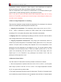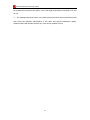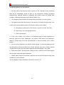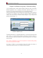
1
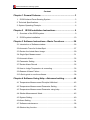
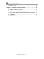
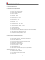
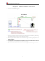
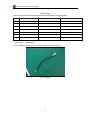
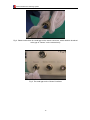
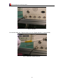
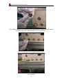
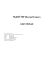
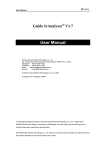
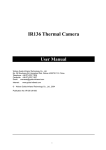
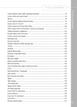
IR236 Infrared Fever Sensing System IR236 Infrared Fever Sensing System User Manual Wuhan Guide Infrared Co., Ltd. No. 26 Shucheng Rd, Hongshan District, Wuhan 430070 P. R. China Telephone: +86-27-8767 1983 Facsimile: +86-27-8767 1927 Email: [email protected] Internet: www.guide-infared.com ® Wuhan Guide Infrared Co., Ltd., 2009 Publication No: GuidIR® 236 UM 009 IR236 Infrared Fever Sensing System Content Chapter 1 General Scheme.......................................................... 3 1. IR236 Infrared Fever Sensing System ................................................3 2. Technical Specifications.........................................................................5 3. System Operating Principle ...................................................................6 Chapter 2 IR236 Installation Instructions ................................ 9 1. Overview of the IR236 system.............................................................9 2. IR236 system installation...................................................................10 Chapter 3 Software Instructions—Basic Functions ................ 26 3.1 Introduction of Software window ........................................................26 3.2 Automatic Trace for Hottest Spot .......................................................27 3.3 Review the Latest Alarm Image .........................................................29 3.4 Single Spot Measurement..................................................................31 3.5 Automatic Alarm.................................................................................32 3.6 Parameter Setting..............................................................................34 3.7 Review Alarm Record ........................................................................35 3.8 How to Judge Temperature is exceeding...........................................36 3.9 Reason of Alarm Failure ....................................................................36 3.10 Quick guide to use the software.......................................................38 Chapter 4 Software Using Help—Advanced setting................ 40 4.1 Temperature Measurement Principle & Method.................................42 4.2 Temperature Measurement Parameter Setting ..................................43 4.3 Temperature Measurement Parameter using help.............................44 4.4 Shutter Measurement Mode:...........................................................45 4.5 System Setting...................................................................................49 4.6 Alarm Setting .....................................................................................51 4.7 Software maintenance .......................................................................58 4.8 Shortcut key function .........................................................................58 IR236 Infrared Fever Sensing System 4.9 IR236 file format ................................................................................59 Chapter 5 Industrial computer setting...................................... 61 5.1 Industrial computer configuration.......................................................61 5.1.1 Industrial computer hardware slot sequence ..................................61 5.1.2 BIOS setting enabling industrial computer powering-on start-up ....61 5.1.3 Precautions.....................................................................................61 5.2 WINDOWS XP setting main points ....................................................62 Wuhan Guide Infrared Co., Ltd. 2 IR236 Infrared Fever Sensing System Chapter 1 General Scheme 1. IR236 Infrared Fever Sensing System Adopting uncooled FPA microbolometer (384X288 pixels) imported from France, IR236’s thermal sensitivity is 0.08 , and it’s image frequency is 50HZ which coincide with standard video signal format PAL system. The technology of IR236 has reached international advanced requirement which is mature and reliable. The whole system consists of IR236 camera, temperature monitoring desk and monitoring center. Temperature monitoring desk gives analysis and treatment to video data, manages corresponding IR236 camera and submit the results to monitoring center. Monitoring center reviews video data from each IR236 camera, while the alarm information is provided by temperature monitoring desk. Mounting disk Visual camera Infrared camera IR236 camera The following chart is for how the IR236 is connected with the working station. 3 IR236 Infrared Fever Sensing System IR236 and the working station 4 IR236 Infrared Fever Sensing System 2. Technical Specifications 2.1 Infrared Technical Specification Detector Type: microbolometer Detector material: polysilicon Pixels:384×288 Pixel pitch:25μm Spectral range:8~14µm Response time:7ms Bad pixels:<1% Temperature range:0℃~50℃ Thermal sensitivity(NETD):0.08℃ Focusing: Motorised Frame frequency: 50Hz Automatic temperature calibration through built-in and outer blackbody Video output format: standard PAL/NTSC Temperature measuring stability:≤0.3℃ 2.2 Visual Camera Technical Specification Scan system: PAL/NTSC,625 lines,25 frame/second Scan mode: interlace scan Synchronous system: internal synchronization mode Effective pixel: 752(H)×582(V) Resolution: more than 480 lines Signal-to-noise ratio: >52 dB Photo sensibility: 0.1Lux Video output: composite video signal 1.0Vp-p(75 Ω/BNC) Operating temperature: -10℃~+50℃ Operating humidity: ≤90%RH Power supply: AC220V/AC240V, 50Hz Power: <5W 5 IR236 Infrared Fever Sensing System 2.3 IR236 DSP Program Function Remote video signal transmission with analysis Remote thermal & visual video transmission, display 1.Monitoring relative video detector’s address and customer symbol with real-time highest spot cursor and temperature value 2.Alarm Remote thermal & visual video transmission with alarm target, display alarm temperature with flicker cursor 3. System Operating Principle 3.1 IR236 Camera IR236 is a imaging equipment composed of thermal imaging camera and visual camera, outputing thermal & visual images of surpervised crowds so that the operator can carry on analysis and treatment in monitoring desk and information center. The FOV range of visual camera is larger than thermal camera, therefore the supervision range of each monitoring desk depends on thermal camera. IR236 can remotely transfer thermal and visual video to information center, displaying temperature analysis result without other hardware and software support. 3.2 Temperature Monitoring Desk Each temperature monitoring desk has one computer to receive thermal & visual image and make necessary control. The monitoring desk will make real-time temperature analysis on received video data and produce sound and light alarm if any. Each computer can manage up to three IR236 camera, and connect with monitoring center via Ethernet. 3.3 Ethernet Monitoring Center (optional) Temperature monitoring desk is connected with monitoring center via Ethernet and send thermal & visual images or alarm signal from every IR236 camera to monitoring center server. The server program can control and make hardware adjustment of each IR236 6 IR236 Infrared Fever Sensing System camera, such as near focusing, far focusing and compensation. It can also choose real-time thermal data of any IR236 camera and make remote analysis on temperature measurement. 4. System Functions Spot temperature measurement on the whole screen, automatic real-time highest, lowest and preset temperature tracing, real-time temperature dynamic measurement on preset spots and areas, display temperature values at the same time. Historical temperature measurement on recorded thermal images, such as temperature measurement on any spot of the whole image, highest/lowest/preset temperature measurement, selected area and analyzed object temperature. Multiple pseudo color palettes or grey display Auto/manual brightness and contrast adjustment Adjustable radiance, distance, ambient temperature and relative humidity Set alarm temperature range and minimum alarm area, realize multi spot alarm and tracing to avoid undetected situation and avoid the interference of object with high temperature such as cigarette and hot water. Set multiple alarm temperature value sections and multiple alarm area, to avoid interference from lamphouse or lighting tube Set alarm timelag and sensitivity Automatically save alarm images or manually switch on image capture function Automatically/manually stop the alarm Indicate alarm object with red color, set alarm into different levels, and display different alarm objects with different colors according to its levels. Objects with elevated temperature are shown in red color with sound and light alarm signal. Voice alarm function can also be available. Alarm image or video can be saved in monitoring PC and transferred to information 7 IR236 Infrared Fever Sensing System center automatically. Remote information center can visit every monitoring computer through IP address, accept real-time thermal & visual video signal of each computer, trace the alarm information synchronistically, and make analysis on the thermal video data received via Ethernet. IR236 camera has CCD visual light channel coordinate with the field of view of thermal channel, and is able to locate objects on visual video with analyzed temperature value. 8 IR236 Infrared Fever Sensing System Chapter 2 IR236 Installation Instructions 1. Overview of the IR236 system 1. The major equipment includes monitoring PC, IR236 camera and blackbody. Monitoring PC includes computer, display screen and power modular. 2. Remote signal includes thermal and visual video image containing temperature and alarm information. 3. The black body is recommended to be installed in front of the infrared camera, direct at the infrared lens, and a little lower than the camera height. 4. The recommended distance between the camera body and the black body is 6 meters. 9 IR236 Infrared Fever Sensing System 2. IR236 system installation 1. Cable Interface Introduction There are totally seven cable interfaces on the back of IR236 camera body: Power & Control Signal 220V AC Fan Sensor Digital Interface Thermal Video Visual Video 1 Visual Video 2 10 IR236 Infrared Fever Sensing System Back Interface Belows are the different cable interfaces with corresponding wires and plugs. No. IR236 Interface Corresponding Wire Plug 1 Power & Control Signal Power Cord 9-core Aviation Plug 2 220V AC Power Cord Plug of two flat pins 3 Sensor 5-core Wire 5-core Aviation Plug 4 Digital Interface Network Cable 5-core Aviation Plug 5 Thermal Video Video Cable BNC Plug 6 Visual Video 1 Video Cable BNC Plug 7 Visual Video 2 Video Cable BNC Plug 3. Instruction-----Install IR236 A. First insert the sensor into the “Sensor” interface of camera body. Fig 1. Sensor 11 IR236 Infrared Fever Sensing System Fig 2. Please notice there is a small gap on the sensor connector, which needs to be aimed at the gap in “Sensor” on the camera body. Fig 3. The small gap on the “Sensor” interface 12 IR236 Infrared Fever Sensing System Fig 4. Finished B. Insert the cable with “Digital Interface” into the “Digital Interface” of camera body. Fig 1. Cable with “Digital Interface” 13 IR236 Infrared Fever Sensing System Fig 2. Please notice there is a small gap on the “Digital Interface” connector, which needs to be aimed at the gap in “Digital Interface” on the camera body. Fig 3. The small gap on the “Digital Interface” interface Fig 4. Finished 14 IR236 Infrared Fever Sensing System C. Insert the cable with “Thermal Video” into the “Thermal Video” of camera body. Fig 1. Cable with “Thermal Video” Fig 2. Aim the connector at the interface, press and rotate the connector until it reaches the correct position. 15 IR236 Infrared Fever Sensing System Fig 3. Finished D. Insert the sensor into the “Visual Video 1” interface of camera body. Fig 1. Cable with “Thermal Video” 16 IR236 Infrared Fever Sensing System Fig 2. Aim the connector at the interface, press and rotate the connector until it reaches the correct position. Fig 3. Finished F. Insert the sensor into the “Visual Video 2” interface of camera body. 17 IR236 Infrared Fever Sensing System Fig 1. Cable with “Visual Video 2” Fig 2. Aim the connector at the interface, press and rotate the connector until it reaches the correct position. Fig 3. Finished 18 IR236 Infrared Fever Sensing System Up till now, the cable connection of IR236 camera body is completed. 4. Video Instruction-----Connect to PC PC Interfaces 19 IR236 Infrared Fever Sensing System There are two video cards installed on PC. One is 1801A card, and the other is VT120 card. Fig 1. 1801A card & VT120 card Fig 2 Connect USB cable of 1801A card to USB interface of PC. 20 IR236 Infrared Fever Sensing System Fig 3 Connect RJ45 connector to the network interface on 1801A card Fig 4. RJ45 connector is one head of Digital Interface 21 IR236 Infrared Fever Sensing System Fig 5 Connect the head of Thermal Video cable onto the “Thermal Video” interface of VT120 card Fig 7 Connect “Visual Video 1” connector onto corresponding interface “Visual Video” on PC 22 IR236 Infrared Fever Sensing System Fig 8 Power switcher from 110V to 220V for visual camera power Fig 9 Connect visual camera power cord to power switcher 23 IR236 Infrared Fever Sensing System Fig 10 “220V 50HZ” power cable for visual camera part Fig 11 Connect one end of power adapor onto the socket. 24 IR236 Infrared Fever Sensing System 110V to 16V Adapter Fig 12 Connect the other end of power adapor to the connector marked with “Power 16V”. 25 IR236 Infrared Fever Sensing System Chapter 3 Software Instructions—Basic Functions IR236 has an easy-operate software which is designed especially for touch screen display. The default resolution of IR236 software is 1024*768. It is highly recommended not to change the resolution of the computer display; otherwise the executive programmer will not run. 3.1 Introduction of Software window The software can run automatically after powering on the PC and enter into the normal working status without any adjustment. Each temperature monitoring desk has one industrial computer responsible for monitoring one or two IR236 camera. Every IR236 camera outputs thermal video signal and visual video signal to the industrial computer and the computer will process the video signals of every IR236. The software window is shown as figure 1-1. The screen window is divided into four small windows. The above two windows are displaying real-time thermal video, and the two windows below are displaying real-time visual video. Thermal real-time video shows temperature measurement information and visual real-time video helps to search and locate the alarm targets. Click these windows to enlarge the image in full screen, and click the full screen image again to return to the default four small windows. Click the round button in the center of panel to open the parameter setting dialog box. When no alarm occurs, the round button is green showing “Menu” on it; when alarm occurs, the round button turns to red and flickers, showing “Alarm” on it. Software version number shows on the left down corner of main menu. Current time and program status shows on the right down side of main menu. 26 IR236 Infrared Fever Sensing System (figure 1-1 Software Window) 3.2 Automatic Trace for Hottest Spot The system can automatically trace the hottest spot on thermal image and mark a green cursor on the hottest spot with temperature data showing above. Press F5 to show or hide the temperature data as shown on figure 1-2. 27 IR236 Infrared Fever Sensing System Hottest Spot Hottest Spot (figure 1-2 Automatic Trace for Hottest Spot) 28 IR236 Infrared Fever Sensing System 3.3 Review the Latest Alarm Image Review prior alarm image on main menu or press the “Menu” button on main menu, below dialog will appear, then click the “Alarm records” on parameter setting dialog box, to see the history alarm record. Shown on figure 1-3、1-4. (figure 1-3 ‘Parameter setting’dialogue) 29 IR236 Infrared Fever Sensing System (figure 1-4 ‘Alarm information’dialogue) 30 IR236 Infrared Fever Sensing System 3.4 Single Spot Measurement Move the mouse to thermal image window, the current temperature value of idicated location will show beside the mouse. Shown as figure 1-5. Display temperature where the mouse is (figure 1-5 move mouse to a single spot to display the current temperature) 31 IR236 Infrared Fever Sensing System 3.5 Automatic Alarm The system can automatically search high temperature targets within the alarm temperature range (normally 37.5 ~ 42.0 ) on thermal video image. When high temperature targets are found in the thermal video, the following alarm information will occur to remind the supervisor to check the alarm record: Sound box of main monitoring center gives out alarm sound; The round main control button in the center of main menu turns to red and flickers, showing “Alarm” on it. Red numbers in yellow background show on the alarm targets on both the thermal and visual image, with the corresponding temperature above the cursors. The software interface of alarming is as shown in figure 1-6. High temp object Alarm button flashing in red in alarm status (figure 1-6 alarming interface) 1) Automatically save a series of visual and thermal alarm images in the hard disk of main monitoring desk for afterwards review. Targets temperature value and cursors will show on alarm images so that the targets can be recognized clearly. 2) Automatically send visual and thermal video images with marked alarm targets to the monitoring center via Ethernet (optional according to different configurations 3) When the alarm signal finishes (high temperature targets get out of the field of view), the two small windows on the lower part of main interface show the 32 IR236 Infrared Fever Sensing System series of alarm images saved correspondingly, as figure 1-7. The newest alarm Yellow data is the thermal picture in the present visual windows Alarm images review button (figure 1-7 display the newest alarm picture) Press and to view the series of images about the latest alarm. 33 alarm IR236 Infrared Fever Sensing System 3.6 Parameter Setting Press button “Menu” to bring out “Parameter Setting” dialog box to set the parameters of video 1 and video 2 and review the alarm record, as figure 1-8. Press it Drag it Press it Press it (figure 1-8 Parameter Setting Dialogue) 3.6.1 Adjust Parameter of Visual Video and Drag the slide or press the arrow button on the two sides of slide to set the parameters of visual video, such as brightness, contrast, hue and saturation. The current value of each parameter is shown simultaneously on the right side of each slide. Click “Default setting” will parameter setting would be the factory default one. 3.6.2 Set Pseudo Color of Thermal Video Press button and bellow the thermal pseudo palettes on the right side of the dialog box or directly click different palettes to display thermal pseudo video with different palettes. Click button “OK” to save the previous setting. Click button “Cancel” to cancel current 34 IR236 Infrared Fever Sensing System modification and exit “Parameter Setting” dialog box. Click button “Default setting” to return the parameter setting to system default values. 3.7 Review Alarm Record Press button “Alarm records” on the left down corner of “Parameter Setting” dialog box to review history alarm record. The basic interface of reviewing the alarm information is shown as figure 1-9. 2 Review the thermal and visual picture at the alarm time 1,Alarm time 3, Set the alarm type (figure1-9 Alarm picture checking) Alarm record list is at the bottom of the screen. Press each alarm record, the corresponding alarm images will be displayed on the upper right corner of the screen, including both the thermal and visual images of each alarm. Press any of the thermal and visual image, enlarged image will display on the upper left corner of the screen. When high temperature targets are found, the system will automatically save corresponding visual and thermal images and make classification according to different times. The operator can set different types for every alarm record from the down right part window of the screen. For example, press up and down buttons in the center of the screen to select between different alarm records, the images captured in each alarm record will show on the upper part of the screen accordingly. In accordance with actual conditions and the saved images, operator can classify each alarm record into different types (press 35 IR236 Infrared Fever Sensing System “unclassified”, “solved”, “Unsolved” or “Other objects”). After classification, the small icon before each alarm record will be with different indication accordingly. When the classification work is finished, the administrator can summarize different types of alarm within a certain detecting period by using advanced function. Note: If you want to review the alarm picture (with temperature data) from its saving directory in PC harddisk, you shall review it with the help of Guide Analyser software (You can find it from PC desktop). 3.8 How to Judge Temperature is exceeding There are three methods to judge whether the temperature of a passenger in the thermal video has exceeded the preset temperature standard or not: 1、Judge by the temperature: The temperature alarm range can be set as 37.5℃~ 42.0℃ . When a passenger is passing by IR236 camera with a high temperature exceeding 37.5℃, the system will produce alarm information automatically. 2、Judge by color: When a passenger is passing by with fever, the color of his face will be red in a large scale which is much easier to judge. 3、Judge by temperature measurement: Using single spot measurement method to measure the surface temperature of forehead(for details, please refer to 4.3). If the value reaches 37.5℃(this value has already been adjusted as the inner temperature of this passenger), then this passenger can be judged as in fever. The second method is taking advantage of the auto-tracing function of IR236 (for detailes, please refer to 4.2). The system can automatically trace the hottest spot of the whole video image. When the highest spot is on the forehead of any passengers and reaches 37.5℃, then the passenger can be judged as in fever. 3.9 Reason of Alarm Failure The main reasons of alarm failure caused by software of IR236 are as follows: 1、Since the temperature of patients with fever is from 37.5℃ to 42.0℃ , so the system alarm range is preset to be from 37.5℃ to 42.0℃. If the target temperature exceeds 42.0℃, the system will not produce alarm. 2、The system has preset the minimum area of alarm target. Therefore, if the target area is much smaller than people’s forehead, such as cigarette ends and flame of cigarette lighter, 36 IR236 Infrared Fever Sensing System the system will not produce any alarm, even if the target temperature is between 37.5 and 42.0℃. 3 、The hardware becomes loose or the field wiring encounters serious interference will also cause the imperfect performance of the video and signal transmission quality. (Please contact with Wuhan Guide if any of the above problem occurs) 37 IR236 Infrared Fever Sensing System 3.10 Quick guide to use the software 1、Everyday when the monitoring center is power on, the computer of each monitoring desk will be automatically power on and run the temperature sensing programme simultaneously. After 15 minutes of preheating, the system enters into normal work condition, measuring temperature and producing alarm if any. 2、The computer produces alarm sound and alarm light flickers to remind operator. 3、The operator shall check the location of red cursors on real-time thermal image. If the cursors locate at the following places, the operator could ignore the alarm: A、Belongings of passengers, such as bento, cup with hot water, hand bag B、Cell phone in use with high temperature C、Neck of passengers 4、If the cursor locates on the head of one passenger and his body temperature is obviously higher than other passengers, the operator shall identify the passenger’s feature in visual image and found that passenger in crowds according to the cursor’s location 5、If the red cursor disappears on real-time thermal image, it means the passenger with high temperature has left the field of view. Please check the red cursor on history thermal & visual alarm images (previous alarm images)saved automatically by the system. 6、Press button “Menu” and then button “Alarm records” to search previous alarm images and the alarm targets with high temperature. 7、Classify alarm images into different categories from the alarm image browsing page according to actual conditons. The flow diagram of alarm treatment is as shown in figure 1-10: 38 IR236 Infrared Fever Sensing System Start work Alarm ? Ye No Go on observe on the Sound box alarms; View real time IR image which alarms Ye Target is still Red cursor in in FOV on Target has left IR image? the Check the red cursor on Check the location of red cursors No history real-time thermal & visual The cursor locates on the The cursor locates on the head of one passenger impedimenta Identify No the passenger’s feature Find that passenger Classify alarm images in crowds into different categories: Solved; Unsolved; Other Subsequent overheated objects sanitary inspection (figure 1-10 flow diagram of alarm treatment) 39 IR236 Infrared Fever Sensing System Chapter 4 Software Using Help—Advanced setting If you are skilled enough in basic software operation method and want to know about advanced applications, such as adjusting measurement parameter setting, etc, you should enter into advanced setting interface and so corresponding operations. Advanced software setting has close relationship with measurement accuracy, therefore it is necessary for the operator to log in before any advanced operation. Press button “Setting” on the lower left side of “Parameter Setting” dialog box, “Log In” dialog box will spring out as shown figure 2-1. (figure 2-1 Operator Log In) The default User Name is “a”, and default Password is “a”. Input correct account and code, press “Confirm”, an “Advanced Setting” dialog box will spring out as shown in figure 2-2. Notice: temperature measurement parameter of advanced setting needn’t to be changed once it is correct. Note:Please do safekeeping to the account and password. In advanced setting, adding new account and password is available. One feature of IR236 is to save parameter change after setting and saving, so measurement parameter needn’t to be changed by general operators. 40 IR236 Infrared Fever Sensing System (figure2-2 ‘advanced setting’dialog box) From advanced setting, the operator can adjust measurement parameter of IR236 camera, make focus setting, set alarm parameter, alarm effective area, and correction coefficient of thermal and visual image, etc. Note:Advanced setting parameters are set by technicians in field and debugged when being assembled at the first time. Do not make any change if you are not sophisticated enough. 41 IR236 Infrared Fever Sensing System 4.1 Temperature Measurement Principle & Method IR236 has two measurement modes: shutter measurement and blackbody measurement. Shutter measurement: when the detector built-in shutter is compensating, measure the target temperature by getting the relationship between thermal image data and target absolute temperature。 Blackbody with constant temperature: use fixed blackbody with constant temperature as reference, get the temperature through building target temperature model in thermal image Shutter and blackbody measurement has its own respective advantages and disadvantages. By utlizing camera shutter, shutter measurement results are stable after IR236 is running for twenty minutes, for the detetor needs to get stable performance step by step. Therefore, parameter correction can only be done when IR236 is running after half an hour. Blackbody measurement take the whole environment condition into consideration, for blackbody shall be located in front of IR236 camera, and measurement results are stable after the blackbody is switched on after ten minutes. Meanwhile if the location of blackbody is changed, the operator needs to reset the blackbody area in the software. 42 IR236 Infrared Fever Sensing System 4.2 Temperature Measurement Parameter Setting The first temperature parameter setting of advanced setting is “1# thermal video”, as shown in figure 2-2: Measurement coefficient: parameters for temperature measurement, can only be set by technicians for temperature measurement. Brightness and Contrast: thermal video brightness and contrast parameter setting. Display brightness and contrast: brightness and contrast of thermal video of monitoring center Temperature correction: difference of body temperature value and body surface temperature measured by IR236. This difference shall be changed according to different environment temperature. Body temperature values getting from clinical thermometer minus the temperature values getting from IR236 equals this correction coefficient. The higher of temperature correction value, the higher of measured temperature value. Hardware control: adjustment of thermal video detector, such as shutter compensation, near focus, far focus, brightness and contrast. Blackbody: using blackbody with constant temperature to measure body temperature. Note:Operator can make change when needed. 43 IR236 Infrared Fever Sensing System 4.3 Temperature Measurement Parameter using help “Coefficient K_F” of measurement parameter is set before delivery and needn’t to be changed. In accordance with shutter and blackbody measurement, only correction coefficient 1 and body inner and surface temperature difference (manual) need to be changed. After correction of temperature measurement coefficient of IR236, the temperature values measured is body surface temperature. There is a difference between people’s body temperature and surface temperature. In order to get a real body temperature, it is necessary to add this difference onto the surface temperature. Actually body surface temperature value varies according to different environment, therefore the difference between body inner and surface temperature varies as the same. Wuhan Guide has summarized body inner and surface temperature difference mathematical model in different environments through a large number of body temperature measurement test. IR236 system can automatically count real-time body inner and surface temperature difference in accordance with this mathematical model. Correction coefficient 1: effective in shutter measurement mode. The measured value will decrease one degree when this parameter increase by 1000, vise versa. Automatic body inner and surface temperature difference: When the parameter is selected, this value will be added automatically in the temperature values. If it is not selected, this value will not give any effect on the final temperature measurement value. This value is effective in both shutter and blackbody measurement mode. Body inner and surface temperature difference (manual): When automatic body inner and surface temperature difference has deviation with specific situation, this parameter needs to be adjusted manually. This parameter shall be zero in normal condition. Increase this parameter by one, the values shown on screen will increase by one. Decrease this parameter by one, the values shown on screen will decrease by one. This parameter can be positive number, negative number and decimal fraction and is effective both in shutter and blackbody measurement mode. Blackbody: Before adopting blackbody measurement mode, please locate blackbody area in the software and input the blackbody’s constant temperature value in the parameter “Blackbody Measurement”. 44 IR236 Infrared Fever Sensing System 4.4 Shutter Measurement Mode: 4.4.1 Shutter Measurement Mode---Correction of measurement coefficient (only for K-F coefficient and correction coefficient 1) The operation schedules are as follows: 1) Cancel “Automatic body inner and surface temperature difference” in the software 2) Power on IR236 3) Put two blackbody in front of IR236, which is 6~8 meters away. Adjust the blackbody’s temperatures to be 39.0℃ and 30.0℃ 4) Leave IR236 and blackbody for about half an hour until both of them in a stable working condition.. 5) Set the system measuring range to be 33.0℃~42.0℃, so that the two blackbody can be detected by IR236. 6) Adjust K_F and correction coefficient 1 in “Advanced Setting” dialog box, make the blackbody temperature on the images same with the actual temperatures of the two blackbody. Notice: K_F and correction coefficient 1 has already been adjusted before delivery, please do not change the two coefficient in general condition. The temperature principle is measure the body surface temperature, add the temperature difference between body inner and surface temperature and get the final body temperature. The alarm function is to adjust whether the target temperature is between 37.5℃ to 40℃. Difference between body inner and surface temperature can be divided into two different parameters: Auto body inner and surface temperature difference, Manual body inner and surface temperature difference, Auto body inner and surface temperature difference is the temperature correction under current environment temperature which is only valid only when the setting has been chosen in the software. Manual body inner and surface temperature difference is valid all the time. This parameter can be used manually when auto mode has deviation. The manual body inner and surface temperature difference can be set as 0. 45 IR236 Infrared Fever Sensing System The temperature measurement formulas are as follows: 1:When Auto body inner and surface temperature difference parameter is selected Body temperature=Body surface temperature + auto body inner and surface temperature difference + manual body inner and surface temperature difference 2:When Auto body inner and surface temperature difference parameter isn’t selected Body temperature=Body surface temperature + manual body inner and surface temperature difference 46 IR236 Infrared Fever Sensing System 4.4.2 Blackbody Measurement Mode--- Correction of measurement coefficient (only adjust manual body inner and surface difference ) 1) Select auto body inner and surface temperature difference in 1# infrared video of advanced setting dialog box. 2) Set blackbody area in the software same as the actual infrared image from “Alarm setting” 3) Input actual blackbody temperature in 1# infrared video. Ensure that the blackbody is switched on for half an hour. 4) Set manual body inner and surface temperature difference as 0 5) Press F5 to view passenger’s forehead and adjust manual body inner and surface temperature difference: Press F5 when return to the main monitoring surface, the highest temperature value will be shown on the screen. Observe the general highest temperature value of crowds. For example, if the general temperature value of forehead is 34.5℃ which is less than the normal forehead temperature (36℃), enter into the infrared video parameter. If the manual temperature difference is 1, then the operator shall change this value into 2.5 (plus 1.5 on the former value 1). If the forehead temperature of crowds shown on the screen is , then the difference shall be changed from 1 to 0. 47 IR236 Infrared Fever Sensing System 4.4.3 Combination and Test of Two Temperature Measurement Modes Press F3 to switch between blackbody measurment mode and shutter measurement mode. Before using both the two modes, please correct the parameter of blackbody and shutter measurement and detect the same target when switching between the two modes. If there is no big difference, that means the system is working well. Summarize: Keep blackbody and IR236 powering on for more than half an hour to make them in a stable working condition Select auto body inner and surface temperature difference Adjust focus (far and near) to make the blackbody shown clearly in infrared image Ensure that the blackbody area setting is correct and the input blackbody temperature is 33℃ Adopt blackbody measurement mode. When manual body inner and surface temperature value is 0, press F5 to see whether people’s forehead temperature is nearly 36℃. In general condition, manual temperature difference 0 is able to measure temperature accurately. When auto temperature difference has difference with actual body’s temperature, change the manual temperature difference to make mass passenger’s forehead temperature to be 36 ℃. After adjusting blackbody measurement mode, keep the same manual temperature difference and select auto temperature difference, switch to shutter measurement mode. (deselect blackbody measurement) Review people’s forehead temperature. If the value is 1℃ less than 36℃, add 1000 on correction coefficient 1;if the value is 1℃ more than 36℃, minus 1000 on correction coefficient. Notice: If the system doesn’t get correct temperature measurement, before changing the coefficient, please check whether the blackbody works well or whether the detector’s location has been changed. 48 IR236 Infrared Fever Sensing System 4.5 System Setting The third page of “Advanced Setting” is “System Setting”, shown as figure 2-4: (Figure 2-4 System Setting) (1) Alarm temperature range: set the highest and lowest temperature range for the target to be alarmed. (2) Red color display: display the target spots in the image within alarmed temperature range in red (3) Minimum pixel area of alarm target: set the minimum pixel area of alarm target in images. If a hot spot’s area is smaller than this value, then the system will not alarm. Only if the hot spot’s area is larger than this value then the system will alarm. Thus the small target with high temperature such as cigarette and cigarette lighter, the system will not 49 IR236 Infrared Fever Sensing System alarm so that the false-alarm probability has decreased. (4) Alarm permission: select this option, then the system will alarm when alarm case occurs or the system won’t response to the alarm case. This option is kept on in default setting and it can be shut off under special condition. (5) Hot spot tracing: select this option, the hot spot and its location will display in both visual and thermal video, or the system will not display it. (6) Alarm images storage route: set the alarm image’s storage route in hard disk. (7) Ethernet setting (optional function): set the IP address of server in monitoring center. (8) Operator management: build, edit or delete the information of operator who can enter the advanced setting. The operator’s logging information is encrypted and stored in hard disk. Please refer to the following figure 2-5. (Figure 2-5 “Operator management” dialog box) 50 IR236 Infrared Fever Sensing System 4.6 Alarm Setting The last page of “Advanced Setting” is “Alarm Setting”, indicated as figure 5-6: (Figure 2-6 Alarm Setting) 51 IR236 Infrared Fever Sensing System 4.6.1 Set shield area There are always objects with high temperature in the monitoring area, such as light box, advertising board and etc. These objects with high temperature are easily to cause false alarm. In order to avoid these interference, IR236 is able to shield and ignore these hot objects. As indicated in figure 2-7, there is reflected light from metal in this video which is easy to cause false-alarm (because it reflects the radiation of heat source with high temperature). 52 IR236 Infrared Fever Sensing System High temperature Black body Shield area (Figure 2-7 Set shield area) In order to avoid false-alarm, please set shield area in accordance with following operations: (1) Press button “Menu” in the center of the screen and “Parameter Setting” dialog box will spring out. (2) Press “Setting” button in “Parameter Setting” dialog box, “Log in” dialog box will spring out. (3) Input correct account and code, then can enter into “Advanced Setting” dialog box. (4) Press “Set Shield Area”, then a graticule will show on the thermal image. (5) According to the figure 2-7, click the areas need to be shielded, and then click “Save Settings” on the right upper side of image to exit and save this setting. Then the system won’t alarm to the shielded place in the future. 53 IR236 Infrared Fever Sensing System 4.6.2 Set Blackbody Area In order to adopt blackbody measurement mode, the blackbody area must be set in the software. And the setting methods are as follows: (1) Press button “Menu” in the center of the screen and then “Parameter Setting” dialog box will spring out. (2) “Setting” button in “Parameter Setting” dialog box, and then “Log in” dialog box will spring out. (3) Input correct account and code to enter into “Advanced Setting” dialog box. (4) Press “Set Blackbody Area”, a dark red rectangular box will show on the thermal video as indicated in figure 2-9. 54 IR236 Infrared Fever Sensing System Dark red rectangular box Black body (Figure 2-9 Area with Ambient Temperature) (5) Drag the rectangular box to the real blackbody’s location displayed on the image. (6) Click “Save Settings” on the right upper side of image to exit and save this setting. Notice: the blackbody’s location must be reset after change. 55 IR236 智能红外体温监测系统 4.6.3 Sensor Calibration The software has two different cursors in both thermal and visual video. Since the field of view of thermal and visual camera are not the same, and the two cameras can not be absolutely parallel to each other, therefore the same single target’s location will be different in thermal and visual video. IR236 software adopts video registration algorithm in order to find the correct relation between cursors in thermal image and visual image. Operator can get the mapping relation of thermal and visual video after registration operation on four or three pairs of spots in thermal and visual video. By this mapping relation, the accurate cursor location in visual video can be calculated. The operation methods are as follows: (1) Press button “Menu” in the center of the screen and then “Parameter Setting” dialog box will spring out. (2) Press “Setting” button in “Parameter Setting” dialog box, then “Log in” dialog box will spring out. (3) Input correct account and code to enter into “Advanced Setting” dialog box. (4) Press button “1# Sensor calibration” in “Advanced Setting”. (5) Four or three green cursors appear on both thermal and visual video and all of them have been marked with numbers. (6) Let one person stand in the field of view of IR236, stretch out his right arm and let his right hand locate on the left upper corner of thermal video. Drag 1# cursor to the hot spot by mouse, release mouse and the l # cursor location is fixed in thermal video. (7) Find this hot spot in visual video, drag 1# cursor to the hot spot by mouse, release mouse and the 1# cursor location is fixed in visual video. The first pair of cursor are settled. (8) Set the location of the second and third pairs of cursor in sequence, shown as 2-12 (9) Click “Save” on the right upper side of image to exit and save this setting. Notice: The same registration method shall be adopted in each video. Once it is fixed, please don’t change it at will, otherwise the target location in visual video will be incorrect. If the location of IR236 is changed, the registration operation must be carried on again. The three cursors for registration shall form a triangular, and the area of this triangular is better to be as large as possible. 1 IR236 Infrared Fever Sensing System The location of these three points is shown as follows: 57 IR236 Infrared Fever Sensing System Figure 2-12 Position of the three aligned spots 4.7 Software maintenance IR236 software has classification function on the images of every alarm. Each computer in monitoring desk are storing pictures everyday. The saved alarm record will be deleted automatically after 12 days. The alarm images in recent two days will be kept completely. The alarm record image in “Other objects” from two days to twelve days later will be deleted automatically. It is better for the operator to visit the alarm image list of each monitoring computer regularly (at least one week), and copy the reliable alarm information from three days to twelve days before for future review. Ensure that the hard disk storage capacity of alarm record index is enough to save alarm images for twelve days. 4.8 Shortcut key function F5 --- the cursor showing the suggestive temperature value F2 --- one line do calibration F8 --- one line switch between blackbody temperature measuring and shutter temperature 58 IR236 Infrared Fever Sensing System measuring Ctrl+E --- switching frozen between infrared and visual light ( that is alarm playback) Ctrl+F --- skimming over the historical images according to the recording date Ctrl+T --- displaying/hiding the ambient temperature, shutter temperature and temperature measuring mode at present Ctrl+X --- allowing/forbidding alarm [the blackbody temperature is not stable at the beginning time when turn on the camera, you can use Ctrl+x to forbid the alarm temporarily] Ctrl+W --- displaying/hiding the shielded area Ctrl+Q --- displaying/hiding blackbody area Ctrl+G --- switching between one line IR auto brightness contrast, manual brightness contrast and auto brightness [In Ctrl+T, you can find the information of the brightness contrast value at present] Numlock ---locking Keystrokes in the keypad:: Num4 decrease the one line IR contrast Num6 increase the one line IR contrast Num2 decrease the one line IR brightness Num8 increase the one line IR brightness Temperature measuring:using mouse to do the real time temperature measuring Starting the soft keyboard:Clicking the left keystroke of the mouse on the top left corner of the main window High temperature target:Tracing the Tmax automatically Exceeding temperature target: give an alarm automatically Ctrl + Shift +F1 prohibit all the hotkey!Except the (Ctrl+T, Ctrl+X, Ctrl+A),and this will be regained after entering the advanced setting. 4.9 IR236 file format IR236RUN (Content)------Executing program content GDGuardD.exe Executing program VideoParaSetting.ini UserInfo CoreDefine ini configuration files (all contents in senior setting) cryptographic account information of senior user Ambient temperature area (constant blackbody), shield area, visual/infrared aligned information irCurve.dat Temperature curve Index (content) Each day alarm information (including alarm time, alarm type) Alarm picture directory(the file path will be E:\alarm picture) ----- generate file directory for each day ----- generate directory according to alarm affair starting time ----- Save specific alarm picture 59 IR236 Infrared Fever Sensing System Each time,when the program is started, it will clear alarm picture directory, only keep alarm information for recent two days, deleting all the other old alarm information. From alarm type, the processing method is: Belongings and others, all delete Fever patient solved, fever patient unsolved and unclassified, all keep it. Alarm directory is saved in a different area of executing program. This is to make sure it can carry alarm information for 14 days. Please forward the useful alarm records others space termly. 60 IR236 智能红外体温监测系统 Chapter 5 Industrial computer setting 5.1 Industrial computer configuration Hardware slot in turn are: mainboard, serial (parallel) port baffle, communication card, video grabber, sound card. 5.1.1 Industrial computer hardware slot sequence Hardware slot sequence: main processing board, series-parallel port baffle plate, communication card, video collection card and sound card. 5.1.2 BIOS setting enabling industrial computer powering-on start-up Purpose: No need to press “Start-up” button, all industrial computer can start-up and run the system program automatically when Powering on monitoring center. Steps: 1 Power on computer and press “Del” to enter BIOS initial interface; 2. Enter “Integrated Periherals”; 3. Enter “On Board I/O chip setup”; 4. Enter “Power on after PWR-Fail” and select “On”; 5. Return to BIOS initial interface and press F10----Enter, save and exit. 5.1.3 Precautions 1. Hardware and driver installation sequence Install sound card and its driver at first. Install communication card next and then install video collection card. 1 IR236 智能红外体温监测系统 5.2 WINDOWS XP setting main points 5.2.1 Cancel screen saver Open “Control panel” , chose“Display” , then you can open the dialog box“Display properties”,chose the item “Screen saver”,picture as followed: Chose “None” Chose “None” in the property of “Screen saver” 5.2.2 Power scheme Click the “Power” in the picture above, you can open the dialog box of “ Power option properties” picture as followed: 1 IR236 Infrared Fever Sensing System Chose “Never” in the items Turn off monitor and turn off hard disk Chose “Never” in the items Turn off monitor and turn off hard disk 5.2.3 Screen resolution Open the “ Control panel” ,chose “Display”, then you can open the dialog box “Display properties”, picture as followed: 63 IR236 Infrared Fever Sensing System Set Screen resolution : 1024×768 Set Screen resolution: 1024×768 5.2.4 IP address setting Open “Control panel”, chose “Network and Internet connections”, and then you can open “Network connections”, double click “ local area connections” to open the “local area connections properties”, picture as followed: 64 IR236 Infrared Fever Sensing System Double check “Internet protocol(TCP/IP)”,the you can open “Internet protocol(TCP/IP) properties” picture as followed: 65 IR236 Infrared Fever Sensing System 5.2.5 Master Volume Set the voice volume as medium,picture as followed: Notice:Do not chose “Mute”. If you set a very low voice volume or chose “Mute”, the alarm will not be heard when there is alarm accident which will omit inspection ;If the volume is too high, the alarm will agitate the passenger. 5.2.6 Date and Time Make sure to set the right date and time. 5.2.7 Sound scheme 66 IR236 Infrared Fever Sensing System Open “Control panel”,chose “Sounds and Audio Devices ”,then you can open “Sounds and Audio Devices Properties”,chose “Sounds” items,picture show as below: Chose “ No Set the sound scheme as “No sound” 5.2.8 Desktop scheme In order to avoid the user operating other programs, we have to empty all the icons on the table top: single clicking of the right button, cancel the item as showed in the picture below: Cancel this item 67 IR236 Infrared Fever Sensing System Cancel the item “Show Desktop Icons”. 68