1
Equipment Overview: Theory of Operation
Interrupt Management – The LCD controller produces two interrupts
to notify the CPU of the completion of important tasks. At the end of the
active region of each display frame, the controller can generate an
interrupt to tell the CPU it has uncontested access to the frame buffer for
a short period, and to synchronize display related processes in the CPU
(such as waveform drawing and scrolling control). A similar interrupt is
provided to signal the completion of fills. Both interrupts may be
disabled and/or acknowledged in the system control registers.
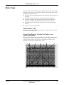
Video Waveform Scroller
There are numerous ways of achieving a scrolling waveform, none of
which is supported by standard LCD controllers. The MAC 5500 provides
scrolling through FPGA hardware placed between the LCD controller
output and the LCD panel input.
To produce the scrolling effect it is necessary to maintain two virtual
image planes, one atop the other. Static (stationary) objects are drawn in
the static plane, which appears nearest the viewer and may be either
opaque or transparent. Dynamic (scrolling) objects are drawn in the
dynamic plane, which appears behind the static plane and is always
opaque, though not necessarily visible. The appearance of motion is
achieved by continuously changing the start point for display of the
dynamic plane from one video frame to the next.
Since the LCD controller does not support multiple image planes, it is
necessary to pack two planes of image data into a single frame buffer.
On the software side (during drawing) this is done by bit masking
operations that allow separate manipulation of two virtual pixels in each
byte of frame buffer memory. Each 8-bit byte holds a pair of pixels, one
from the static plane and one from the dynamic plane.
On the hardware side, part of each frame buffer byte (the static plane) is
played directly into the LCD after suitable color mapping. The remainder
of the byte (the dynamic plane) is stored in a 1 line temporal buffer before
being displayed. The amount of delay applied to the line buffer before
merging it with the static image data determines its placement on the
screen. By gradually changing the delay, the dynamic image can be made
to scroll.
Color Lookup Table (CLUT)
Generally the dynamic plane is filled with waveforms and perhaps a few
characters of text. The static plane often contains text messages, icons,
buttons and graphics. The greater variety of object types displayed in the
static plane demands a wider range of colors. For this reason, each video
data byte is split asymmetrically into five bits of static pixel data and
three bits of dynamic pixel data. This has come to be known as 5.3
format.
The 5.3 format provides a palette of 2^3=8 colors for dynamic objects and
(2^5)-1=31 colors for static objects (1 of the colors is transparent, leaving
31 real colors). In practice, to “freeze” dynamic objects in the static plane
requires that the 8 dynamic colors be replicated in the static color map,
leaving only 31-8=23 new colors available for static objects. The FPGA
implements a writable color lookup table (CLUT) to map the pixel values
to sensible colors on the LCD. The CLUT provides 32- to 24-bit entries,
Revision A
MAC 5500 resting ECG analysis system
2020299-020
2-21