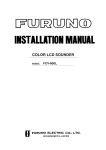
1
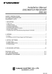
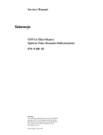
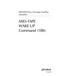
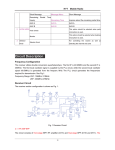
R
INSTALLATION MANUAL
VHF RADIOTELEPHONE FM-8500
This manual provides the information necessary
for the installation of the FURUNO FM-8500
VHF Radiotelephone. For best performance
please follow the recommended procedures.
Table of Contents
Page
1. System Configuration ........... 1
2. Equipment Lists .................... 2
3. Mounting .............................. 8
4. Connections......................... 14
5. Initial Settings ...................... 21
Outline Drawings ....................D-1
Interconnection Diagram ....... S-1
Schematic Diagrams .............. S-2
C
Yo u r L o c a l A g e n t/D e a le r
9-52, A shihara-cho,
N ishinom iya, Japan
Te l e p h o n e :
Te l e f a x :
0 7 9 8 -6 5 -2 111
0798-65-4200
A ll rig h ts re s e rv e d .
Printed in Japan
PU B. N o. IM E-56030-M
(T E N I)
FM -8500
FIRST
EDITIO N
M
:
:
MAR. 2000
JUL. 4, 2001
SAFETY INSTRUCTIONS
"NOTICE", "CAUTION" and "WARNING" notices appear throughout this manual. It is the
responsibility of the installer of the equipment to read, understand and follow these notices. If you have any questions regarding these safety instructions, please contact a
FURUNO agent or dealer.
WARNING
This notice indicates a potentially
hazardous situation which, if not
avoided, could result in death or
serious injury.
CAUTION
This notice indicates a potentially
hazardous situation which, if not
avoided, could result in minor or
moderate injury or property
damage.
NOTICE
This notice indicates an unsafe
practice which, if not avoided, could
result in property damage or
equipment malfunction.
i
i
WARNING
Hazardous voltage.
Can shock, burn or cause
serious injury.
Do not work inside the equipment unless totally familiar
with electrical circuits.
Turn off the power at the mains switchboard before beginning the installation.
Post a warning sign near the switchboard
to indicate that power should not be
applied while the equipment is being
installed.
Electrical shock, serious injury or fire can
result if the power is not turned off or is
applied while the equipment is being
installed.
ii
CAUTION
Ground the equipment to
prevent electrical shock
and mutual interference.
Confirm that the power supply voltage
is compatible with the voltage rating
of the equipment.
Connection to the wrong power supply
can cause fire or equipment damage.
The voltage rating appears on the label
at the rear of the display unit.
Observe the compass safe distance to
prevent deviation of a magnetic
compass.
Transceiver
Unit
Power Supply
(option)
Standard
compass
Steering
compass
1.6 m
1.2 m
0.9 m
0.7 m
1. System Configuration
VHF
Antenna
DSC Antenna
Navigation
Device
Distress
Message
Controller
DMC-5
Handset
TRANSCEIVER UNIT
FM-8500
Remote
Station DB-700
or Distributor
DB-500
Handset
Ship’s Mains
100/220 VAC
50/60 Hz, 1φ
Radio Battery
24 VDC
Mic
Receptacle
Box
AC/DC
Power Supply
Unit
PR-300
Printer
Interface
IF-8500
Printer
PP-510
External
Speaker
1
2. Equipment Lists
Standard Supply
Name
1
Type
Qty
Mass
(kg)
1
6
Transceiver Unit FM-8500USA
For USA
Except USA
FM-8500-S
2
Accessories
FP05-04410
1 Set
005-389-140
3
Installation
Materials
CP05-06800
1 Set
005-386-000
4
Document
OME-56030-*
1
000-807-629
OSE-56030-*
1
000-807-631
IME-56030-*
1
000-807-633
E5-96001-0*
1
000-807-789
E5-92001-0*
1
000-805-799
*: Version number
2
Remarks/Code No.
Optional Equipment
Name
Type
Code No.
Remarks
1
AC-DC Power
Supply
PR-300
000-130-431
2
VHF Antenna
RA-106
000-134-763
3
Whip Antenna
150M-W2VN
000-113-498
4
Antenna Fixing
Plate
4-310071
000-572-184
5
Cable Assembly
05S9104
000-135-011
6
Coaxial Cable
5D-2V *10M*
000-111-063
7
Coaxial Cable
5D-2V *20M*
000-111-064
8
Connector
M-P-5
000-503-678
9
Dynamic Mic Set
OP05-57
000-045-775
HS-6000FZ5(Handset)
10 Carbon Mic Set
OP05-58
000-045-776
HS-6000FZ6(Handset)
11 Flush Mount Kit
OP05-73
005-386-010
12 Remote Station
RB-700
13 Distributor
DB-500
14 Twisted Cable
CO-SPEVV-SB-C
0.2x2P
000-111-680
5 m for
DMC/NMEA/IF-8500
CO-SPEVV-SB-C
0.2x2P
000-120-792
10 m for
DMC/NMEA/IF-8500
CO-SPEVV-SB-C
0.2x2P
000-120-793
15 m for
DMC/NMEA/IF-8500
CO-SPEVV-SB-C
0.2x2P
000-120-794
20 m for
DMC/NMEA/IF-8500
CO-SPEVV-SB-C
0.2x2P
000-120-214
30 m for
DMC/NMEA/IF-8500
15 Printer
PP-510
16 Distress Message
Controler
DMC-5
17 Printer Interface
IF-8500
18 External
Loudspeaker
SEM-21Q
000-144-917
19 Connector
SRCN6A21-16P
000-508-664
RG-58/U
3
4
5
6
7
3. Mounting
Transceiver Unit
General mounting considerations
Determine the mounting location for the transceiver unit considering
operator convenience, proximity to the power source and the ground
location. Keep these and the following points in mind when selecting
a mounting location.
• Locate the unit in a place free of water spray and water splash.
• Keep the unit out of direct sunlight because of heat that can build
up inside the unit.
• Leave a little slack in cables to allow a service technician to move
the radio from its usual location with the cables connected. This
lets him make tuning and other adjustments on a “live” set.
• Do not install the unit where flammable gases are stored.
• Select a well ventilated area.
• Ensure the mounting location is strong enough to support the weight
of the unit (6 kg) under the condition of continued vibration normally encountered aboard the vessel. If necessary, reinforce the
mounting area with a doubling plate or lining block.
• Leave sufficient space at the sides and rear of the unit for maintenance and service purposes and to provide for circulation of cooling air. The minimum service clearance appears in Figure 2.
• For flush mounting, select a location where the LCD can be easily viewed.
• The transceiver unit will affect a magnetic compass if placed too
near the compass. Observe the compass safe distance to prevent
deviation of a magnetic compass;
Standard compass: 1.6 m
Steering compass: 1.2 m
Note:
Take great care not to press the DISTRESS switch during the
installation. If you accidentally press the switch, immediately turn
off the equipment and contact appropriate authority by telephone.
8
Overview of mounting methods
Overhead
Flush Mount
Tabletop
Bulkhead
Figure 1 Overview of mounting methods
9
Mounting procedure for tabletop, overhead and
bulkhead mounting
1. Using the hanger as a template, mark fixing holes in the mounting location.
2. Fix the hanger to the mounting location with wood screws and
washers (supplied). (For added support, use nuts, bolts and washers instead of wood screws.)
3. Screw the knob bolts with washers into the transceiver unit.
4. Set the transceiver unit to the hanger and tighten knob bolts.
• All dimensions in millimeters.
• For added support, fasten hanger with nuts, bolts and washers (local supply) instead of wood screws.
• Leave sufficient space at the sides and rear of the unit to
provide easy access for maintenance and service. The minimum service clearance is shown in the figure.
Figure 2 Mounting dimensions for tabletop, overhead and bulkhead
mounting
10
The mounting procedure for flush mount (option)
Requires flush mount kit OP05-73 (optional supply). Prepare a cutout in the mounting location whose dimensions are as shown in the
Figure 3.
261
25
max 14
10
10
106
205
20
150
Figure 3 Mounting dimensions for flush mount
VHF Antenna
The antenna requirements
Any good quality antenna meeting the requirements shown below
may be used. A high-gain antenna is preferable.
•
•
•
•
•
Frequency range:
Impedance:
Polarization:
Handling power:
Quality:
155 to 164 MHz
50 ohms
Vertical
30 W/ min
Able to withstand marine environment
Mounting considerations
• The antenna should be well separated from nearby antennas, masts,
and other interfering objects.
• The higher the antenna is mounted above the horizon, the further
the communications range.
Mounting procedure
The basic mounting procedure for antennas supplied by FURUNO is
as follows, however consult appropriate outline drawing for details.
1. Fasten the antenna bracket to the stanchion.
2. Set the antenna to the antenna bracket and tighten bolts.
3. Screw the coaxial cable plug into the antenna.
11
DSC Antenna
The antenna should be well separated from nearby antennas, masts,
and other interfering objects.
The mounting procedure is the same as that for the VHF antenna,
however consult appropriate outline drawing for details.
Handset Hanger
The handset hanger can be mounted at the front or rear of the transceiver unit. To mount the hanger at the rear of the unit, a connector
and connector assembly are required (option). The mounting location should provide easy access to front panel controls while operating the handset. Also, the length of the standard handset cable is 50
cm, so locate the handset hanger within 50 cm of the unit. (Longer
cables are available optionally.)
Power Supply (option)
For Convention vessels, both AC and DC power must be fed to the
FM-8500, via an AC/DC power supply. When AC input fails, DC
power is supplied. FURUNO can supply an AC/DC power supply
unit, the PR-300.
Mounting considerations
When selecting a mounting location, keep in mind the following
points.
• Select a location which provides adequate ventilation.
• The location must be clean and dry.
• The mounting location must be able to support the weight of the
unit (14.5 kg) under the continued conditions of vibration normally
encountered aboard the vessel. If necessary, reinforce the mounting location.
• The PR-300 will affect a magnetic compass if it is placed to near
the compass. Observe the compass safe distance to prevent deviation of a magnetic compass;
Standard compass: 0.9 m
Steering compass: 0.7 m
Mounting
Refer to outline drawing.
12
Printer Interface (option)
Printer Interface IF-8500 is connected between the printer PP-510
and the transceiver unit. See outline drawing on page D-11.
Printer (option)
Refer to the printer outline drawing on page D-12 for mounting
dimensions.
1. Select a flat surface.
2. Fix the mounting base to the mounting location with four screws
(supplied).
3. Lay the printer on the top of the mounting base and fasten it with
the mounting fixtures (two at each side and one at rear).
Mounting Fixture
Mounting Fixture
Mounting Dimensions 300 (H) × 396 (W) mm
Figure 4 Mounting of Printer PP-510
External Loudspeaker (option)
The external loudspeaker can be installed on a tabletop, the overhead
or a bulkhead. Fasten the loudspeaker to the mounting location with
tapping screw, or nuts, bolts and washers. For mounting dimensions,
see the outline drawing on page D-8.
13
4. Connections
Overview
Figure 5 shows where to connect various equipment at the rear of the
transceiver unit.
REMOTE
Covered with dummy
plate on standard
equipment.
CH70 ANT
Connect DSC
antenna here.
EXT SP
Connects external
loudspeaker.
REMOTE
CH70
RX ANT
24VDC
NMEA
ANT
EXT SP
DMC
PRINTER
WING HANDSET
HANDSET
HANDSET MIC
Connects handset
mic.
24VDC
Connects power
cable.
NMEA
Connects navigator
(Loran C, GPS).
ANT
Connects
antenna.
DMC
PRINTER
Connects Distress Connects Printer
Message Controller Interface IF-8500.
DMC-5.
WING HANDSET
Connects wing
handset.
Figure 5 FM-8500, rear view
Connection of Power Supply
Convention vessels, 100/220 VAC ship’s mains
Convention vessels must supply both AC and DC power to the FM8500, via an AC/DC power supply unit. Both AC and DC are supplied by the AC/DC power supply unit, and when AC input fails DC
power is activated.
Connect the radio battery to the DC IN terminal on the PR-300. Connect the AC ship’s mains to the AC IN terminal on the PR-300.
14
Radio battery (24 VDC)
Attach the connector supplied to the power cable and plug it into the
24VDC connector at the rear of the transceiver unit. Connect the wire
ends to the radio battery line.
Connection of VHF Antenna
The VHF antenna is connected to the transceiver unit with a 50 ohm
coaxial cable, type 5D-2V. Be sure to leave some slack in the cable
for future service and maintenance.
Lay the coaxial cable and attach an M-type plug to the cable (if necessary) as follows.
1. Remove the sheath by 20 mm.
2. Bare 13 mm of the center conductor. Trim braided shield by 5
mm and tin.
3. Slide coupling ring onto cable.
4. Screw the plug assembly on the cable.
5. Solder plug assembly to braided shield through solder holes. Solder contact sleeve to conductor.
6. Screw coupling ring into plug assembly.
Screw the plug into the ANT connector at the rear of the transceiver
unit.
Figure 6 How to attach the M-type plug to the coaxial cable
15
Connection of DSC Antenna
The DSC antenna is connected to the transceiver unit with a 50 ohm
coaxial cable, type 5D-2V. Attach an M-type plug to the cable (if
necessary) as shown in Figure 6. Screw the plug into the CH70 ANT
connector at the rear of the transceiver unit.
Connection of Handset
Connect the handset cable to the HANDSET connector on the rear
panel.
Grounding the Transceiver Unit
Fasten a ground wire (local supply) between the GND terminal at the
rear of the transceiver unit and ship’s hull (or ground bus).
CAUTION
Ground the equipment to
prevent electrical shock
and mutual interference.
Connection of AC/DC Power Supply Unit PR-300 (option)
Changing tap connections
Change the tap connections of the transformer according to input
voltage.
110
110
100
100V
10%
FAN
0
110
100
110V
10%
0
110
100
200V
10%
0
100
220V
10%
0
110
110
110
110
100
100
100
100
0
0
0
0
NC
NC
NC
NC
100
100
100
100
0
FAN
0
FAN
0
FAN
0
100VAC SHIP'S MAINS 110VAC SHIP'S MAINS 200VAC SHIP'S MAINS 200VAC SHIP'S MAINS
Figure 7 Tap connections in the PR-300
16
Changing the power fuse
Change the power fuse according to input voltage as follows.
Input
100/110 VAC
10A
200/220 VAC
5A
Lamp
(red)
Lamp
(green)
FURUNO
PR-300
100V 10A
220V 5A
AC power
source switch
Fuse
20A
ON
ON
OFF
OFF
AC IN
DC IN
Fuse for ship's mains
DC power
source switch
DC OUT
Figure 8 AC-DC power supply unit PR-300, rear view
Ground
Connect a ground wire between ship’s superstructure and a fixing
screw on the PR-300.
CAUTION
Ground the equipment to
prevent electrical shock
and mutual interference.
17
Connection of External Equipment (options)
Equipment available
The following equipment can be connected to the FM-8500:
• Distress Message Controller DMC-5
• Remote Station RB-700 (or Distributor DB-500)
• Navigator : the FM-8500 can receive the following data sentences
in NMEA format (Ver. 1.5).
GLL: Latitude and longitude
Talker
Sentence
GP, LC, DE, TR, LA, OM
GLL
RMA: Loran C data (L/L, LOPs, etc.)
GP, TR
RMC
Note:
LC
RMA
For RMC, data (month an day) are entered in
the log and for GLL, time (hour/min/sec) is
entered in the log.
RMC: Generic navigation information
• MIC Receptacle Box and Wing Handset
• External Loudspeaker
• Printer Interface IF-8500
REMOTE
Connect Remote Station
RB-700 or Distributor
DB-500 here.
EXT SP
Connect external
loudspeaker here.
REMOTE
CH70
RX ANT
24VDC
NMEA
NMEA
Connect
navigator
(Loran C,
GPS) here.
ANT
EXT SP
DMC
PRINTER
DMC
Connect Distress
Message Controller
DMC-5 here.
WING HANDSET
HANDSET
WING HANDSET
Connect wing
handset here.
PRINTER
Connect Printer
Interface IF-8500 here.
Figure 9 FM-8500, rear view, showing location of external
equipment connectors
18
Cables required
Equipment
Cable required
Remote Station RB-700 or
Distributor DB-500
CO-SPEVV-SB-C 0.2x10P(10P cable w/armor, no connectors)
or 05S0721(w/connectors)
Distress Message Controller
DMC-5
CO-SPEVV-SB-C 0.2x2P
Navigator
CO-SPEVV-SB-C 0.2x2P
Wing handset
Two types of wing handsets are available: HS-6000FZ6 (carbon MIC)
and HS-6000FZ5 (dynamic MIC). Change jumper connections on
the CONTROLLER Board as shown in Figure 9 according to handset connected.
Jumper Block
JP2
JP2 setting
D
C
For carbon MIC
(Default setting)
D
C
For dynamic MIC
(Also, turn R152 fully
counterclockwise.)
JP2
R152
CONTROLLER Board
Jumper Block and R152
Figure 10 Transceiver unit, top view, showing CONTROLLER
Board
19
Procedure
1. Release write protection, referring to service manual for the
procedure.
TEST display appears.
TEST VHF ch70
manual
Figure 10a Test display
2. Press SELECT key, 9 key, RT key, and then press ENT key four
times.
RT4-TxAF MONITOR
OFF[1] ON[2]
Figure 10b TxAF monitor screen
3. Select ON and press ENT key.
4. Press CANCEL key nine times to return to the TEST display.
TEST VHF ch70
manual
Figure 10c test screen
5. Rotate VR152 clockwise so that the volume of the dynamic MIC
is maximum.
Rotate clockwise
Marking
VR152
0Ω
From bottom center;
Leftward 45°: 0 ohm
Rightward 45°: Maximum
MAX
Figure 10d VR152 setting
6. Select “OFF” on the “RT-4-TxAF MONITOR” screen and press
ENT key.
7. Re-write protect settings.
20
Printer Interface
Refer to page S-1.
Figure 10e
21
5. Initial Settings
Overview
This chapter provides the information necessary for setting up the
following:
1) Ship's ID number
2) DSC block
3) VHF block
4) Channel system
5) Protection (Lock initial settings)
Entering Ship's ID
Procedure
1. Rotate the VOLUME knob clockwise to turn on the equipment.
“TEST” blinks.
TEST VHF CH70
auto
Figure 11 Test screen
2. Press the SELECT key. The Setup menu appears.
Setup menu < M.position >
1 2 3 4 6 9
ALM
Figure 12 Setup menu
3. Press the 9 key to display the system menu.
System < ROM version >
V P ID DSC RT CH PO
Figure 13 System menu
4. Press the right arrow key to select ID.
5. Press the ENT key.
22
System < Own-ID number >
V P ID DSC RT CH PO
Figure 14
6. Enter ship's ID (nine digits). To correct the data entered, press the
CANCEL key and reenter ID number.
7. Press the ENT key.
Setting up DSC Block
When two FM-8500s are installed, designate one as Main (CH70)
and the other as Sub (VHF). The default setting is “CH70” as main
unit. For sub unit, do the following.
Procedure
1. Rotate the VOLUME knob on the sub FM-8500 clockwise to
turn it on.
2. Press the SELECT and 9 keys to display the System menu.
3. Press right arrow key to select DSC.
4. Press the ENT key.
DSC:receiver < CH70 >
CH70[1]
VHF[2]
Figure 15
5. Press the 2 key to select VHF[2].
6. Press the ENT key. The System menu appears.
Setting up the VHF Block
Procedure
Highlighted items in this section are default settings.
1. Press right arrow key to select RT at the System menu.
2. Press the ENT key.
RT 1-Mode:USA/WX< OFF >
OFF[1]
ON[2]
Figure 16
23
3. Disable or enable the USA/WX mode.
4. Press the ENT key. The following menu appears.
RT 1-Mode:private< OFF >
OFF[1]
ON[2]
Figure 17
5. Disable or enable the PRIVATE channel mode.
6. Press the ENT key.
RT 2-Hook work:CH16< ON >
ON[1]
OFF[2]
Figure 18
7. Disable or enable watch on CH16 when handset is on hook.
8. Press the ENT key.
RT 2-Hook work:SP< ON >
ON[1]
OFF[2]
Figure 19
9. Disable or enable speaker when handset is on hook.
10. Press the ENT key.
RT 3-Time out timer< OFF >
OFF[1]
ON[2]
Figure 20
11. Disable or continue after a long transmission. For USA, set to
ON. Not effective unless USA mode is enabled.
12. Press the ENT key.
RT 4-Tx AF monitor< OFF >
OFF[1]
ON[2]
Figure 21
13. Disable or enable monitoring of external equipment; for example,
Remote Station RB-700.
14. Press the ENT key.
24
RT 5-Auto 1W< ON >
ON[1]
OFF[2]
Figure 22
15. Disable or enable automatic power reduction (to 1 W) after a
long transmission.
16. Press the ENT key.
RT 6-Dual watch< ON >
ON[1]
OFF[2]
Figure 23
17. Disable or enable dual watch.
18. Press the ENT key.
RT 6-Scanning< ON >
ON[1]
OFF[2]
Figure 24
19. Disable or enable channel scanning.
20. Press the ENT key.
RT 7-Auto SQ<L00 H03 HO30>
LOW= 0 HIGH HOLD
Figure 25
21. Enter lowest limit of voice frequency (average) which opens automatic squelch. Enter value by the following formula
Setting value x 50 = Low Frequency (Hz)
For example, if the lowest average frequency which opens the
automatic squelch is 50 Hz, enter 1 (1 x 50 = 50 Hz).
22. Press the ENT key to select HIGH.
23. Enter highest frequency which opens automatic squelch.
Setting value x 50 = High Frequency (Hz)
Default setting is 3 so that when the average frequency of received signal is higher than 150 Hz, audio signal is muted.
24. Press the ENT key to select HOLD.
25
25. Enter squelch hold time in two digits, by following the formula
below.
Setting value x 20 (msec) = Time desired
26. Press the ENT key. The display changes to the System menu.
Setting Channel System
Procedure
1. Press the right arrow key to select CH.
2. Press the ENT key. The international channel setting display appears.
INTL CH:016<TX SIMP HI>
ENABLE=TX[1] RX[2] UN[3]
Figure 26
3. Rotate CHANNEL Knob to select channel to set.
TX: Transmission and reception available
RX: Reception only
UN: Transmission and reception prohibited
4. Press 1 (TX), 2 (RX) or 3 (UN) key depending on channel. Figure 27 shows screen appearance when TX is selected.
INTL CH001<TX DUP HI>
TELECOM=SIMP[1] DUP[2]
Figure 27
5. Select communication mode; press 1 for simplex, or 2 for duplex.
INTL CH001<TX SIMP HI>
TX POWER=HIGH[1] LOW[2]
Figure 28
6. Select TX power; press 1 for high output power, or 2 for low
output power.
7. Repeat steps 3 to 6 to set other channels.
8. To select other mode ( USA, WX or Private), press the CHANNEL knob.
9. Repeat steps 3 to 6 for USA or WX channel.
26
For private channels mode
10. Press the CHANNEL knob to select private channel mode.
P01/CH123<TX SIMP LOW>
PRIV No.SELECT:[<][>]key
Figure 29
11. Press the arrow keys to select private channel (P01 to P20) to set.
P02/CH---<-- ---- ---->
PRIV No.SELECT:[<][>]key
Figure 30
12. Press the ENT key.
P02/CH001<UNABLE>
ENABLE=TX[1] RX[2] UN[3]
Figure 31
13. Rotate the CHANNEL knob to select a channel.
P02/CH234<UNABLE>
ENABLE=TX[1] RX[2] UN[3]
Figure 32
14. Select telecom mode; 1 for simplex or 2 for duplex.
P02/CH234<TX SIMP LOW>
TELECOM=SIMP[1] DUP[2]
Figure 33
15. Select communication mode; 1 for simplex, or 2 for duplex.
P02/CH234<TX SIMP LOW>
TX POWER=HIGH[1] LOW[2]
Figure 34
16. Select TX power; 1 for high output power, or 2 for low output
power.
17. To set other private channels, repeat steps 11 to 16.
18. Finally, press the CANCEL key. The System menu display appears.
27
Locking Initial Settings
Do the following to lock initial settings and enable normal operation.
1. Press the right arrow key to select P.
2. Press the ENT key. The following appears.
Protection< OFF >
ON
OFF
Figure 35
3. Press the left arrow key to select ON.
4. Press the ENT key.
All initial settings are locked and the equipment is ready for operation.
28