1
Computer Science
.LP6DQGUHKDY
&KULVWHU7KXQ
5HPRWH0RQLWRULQJDQG&RQWURORID%XLOGLQJ
Bachelor’s Project
2000-22
5HPRWH0RQLWRULQJDQG&RQWURORID%XLOGLQJ
.LP6DQGUHKDY
&KULVWHU7KXQ
© 2000 Kim Sandrehav, Christer Thun and University of Karlstad
This report is submitted in partial fulfillment of the requirements for the
Bachelor’s degree in Computer Science. All material in this report which is
not our own work has been identified and no material is included for which
a degree has previously been conferred.
Kim Sandrehav
Christer Thun
Approved, 2000-06-08
Advisor: Dimitri Ossipov
Examiner: Stefan Lindskog
iii
$EVWUDFW
This paper is a thesis investigating the possibilities to create a system for controlling and
monitoring a remote object, for instance a building. It involves data acquisition, monitoring,
alarm and controlling. Also, it introduces the LabVIEW product line as well as the G
programming language to the reader. Great weight has been put into an investigation in SMS
communication. The workplace has been Enator Teknik Karlstad, a subdivision of
TietoEnator, during the spring semester of 2000.
The work has resulted in a working application for monitoring temperature and noise. The
measured values are displayed on a screen. Functionality for logging data to disk has been
added, as well as the possibility to view monitoring in real-time through a web browser
interface. Some functionality for alarming as well as for control according to the results of the
SMS Investigation has also been implemented.
v
vi
&RQWHQWV
,QWURGXFWLRQ 1.1
Background............................................................................................................ 1
1.2
Problem.................................................................................................................. 1
*RDOV 2.1
Purpose .................................................................................................................. 3
2.2
Expected results ..................................................................................................... 3
2.3
Time Plan............................................................................................................... 4
'DWD$FTXLVLWLRQDQG0RQLWRULQJ 3.1
About DAQ............................................................................................................ 5
3.2
Monitoring ............................................................................................................. 7
3.3
•
•
•
•
•
What is to be measured? ......................................................................................................7
When is data sampled?.........................................................................................................7
Where does monitoring take place? ......................................................................................7
Why monitor?......................................................................................................................7
How to monitor?..................................................................................................................7
Future Applications ................................................................................................ 8
/DE9,(:,QWURGXFWLRQ 6\VWHP'HVLJQ 5.1
The LabVIEW Core ............................................................................................. 11
5.2
Message Handler.................................................................................................. 12
5.3
Web Server .......................................................................................................... 12
5.4
System Architecture ............................................................................................. 13
8VHU±6\VWHP,QWHUDFWLRQV 6.1
Local Interactions................................................................................................. 15
6.1.1
6.1.2
6.1.3
6.1.4
6.1.5
6.2
Welcome ...........................................................................................................................15
Main Menu........................................................................................................................15
Monitor .............................................................................................................................15
View Old Data...................................................................................................................15
Preferences ........................................................................................................................16
Remote Interactions ............................................................................................. 16
6.2.1 WWW ...............................................................................................................................16
vii
6.2.2 Messaging .........................................................................................................................16
0HVVDJLQJ6HUYLFH 7.1
Investigation for SMS Functionality..................................................................... 17
7.1.1
7.1.2
7.1.3
7.1.4
7.2
About SMS........................................................................................................................17
SMS Investigation Results .................................................................................................18
Software............................................................................................................................19
Conclusions.......................................................................................................................21
Other Messaging Services .................................................................................... 22
7.2.1 About Email ......................................................................................................................22
7.2.2 Email Service in the Application ........................................................................................23
6\VWHP(YHQWV 8.1
8.2
Data Flow ............................................................................................................ 25
Events in the LabVIEW Core ............................................................................... 26
8.2.1 Possible Events..................................................................................................................26
8.2.2 Communication Syntax......................................................................................................26
'HWDLOHG6\VWHP'HVLJQ 9.1
System Analysis................................................................................................... 27
9.1.1 Message Passing and Global Variables...............................................................................28
9.1.2 Instrument Individuality.....................................................................................................28
9.2
Subsystem Analysis ............................................................................................. 29
9.2.1 Welcome.vi .......................................................................................................................29
9.2.2 Menu.vi.............................................................................................................................29
9.2.3 Monitor.vi .........................................................................................................................29
9.2.4 Olddata.vi..........................................................................................................................30
9.2.5 Preferences.vi ....................................................................................................................31
9.2.6 Templogger.vi and Noiselogger.vi .....................................................................................31
9.2.7 LoadPrefs.vi ......................................................................................................................32
9.2.8 SavePrefs.vi.......................................................................................................................32
9.2.9 GetSeconds.vi....................................................................................................................32
9.2.10 MessageHandler.vi ............................................................................................................32
9.2.11 GetMail.vi .........................................................................................................................32
9.2.12 SendMail.vi .......................................................................................................................33
9.2.13 SendSMS.vi.......................................................................................................................33
9.2.14 Globals.vi ..........................................................................................................................33
&RQFOXVLRQVDQG5HVXOWV$QDO\VLV 10.1 Results As Expected? ........................................................................................... 35
10.2 Time Plan Accordance ......................................................................................... 36
10.3 Maintainability of the System............................................................................... 36
10.3.1 Performance ......................................................................................................................36
10.3.2 Maintenance ......................................................................................................................37
10.4 Final words .......................................................................................................... 37
viii
5HIHUHQFHV $
$EEUHYLDWLRQV %
6FUHHQVKRWV Welcome.vi ................................................................................................................... 43
Menu.vi......................................................................................................................... 43
Monitor.vi ..................................................................................................................... 44
Olddata.vi ..................................................................................................................... 44
Preferences.vi................................................................................................................ 45
Menu.vi Diagram .......................................................................................................... 46
Monitor.vi seen through a web browser ......................................................................... 47
ix
/LVWRI)LJXUHV
Fig. 2.1 Time Plan .......................................................................................................... 4
Fig. 3.1 Data Acquisition Model..................................................................................... 5
Fig. 3.2 DAQ Signal Accessory...................................................................................... 6
Fig. 4.1 Front Panel ...................................................................................................... 10
Fig. 4.2 Dataflow Diagram ........................................................................................... 10
xi
/LVWRI7DEOHV
Table 5.1 Parts of System Survey .................................................................................. 11
Table 7.1 Supported Phones in Message Master ............................................................ 21
Table 8.1 Communication Syntax.................................................................................. 26
Table 9.1 VIs in use....................................................................................................... 27
Table 9.2 Data flow to and from the instruments ........................................................... 28
Table 9.3 Preferences .................................................................................................... 31
xii
,QWURGXFWLRQ
This report describes “Project Z”. A research and programming assignment at TietoEnator,
serving as a Bachelor’s Project in Computer Science at University of Karlstad, spring
semester of 2000. This report guides the reader through the goals, data acquisition, the
LabVIEW environment, design, interactions, messaging service and SMS investigation,
events, detailed design, conclusions and results analysis. All acronyms are listed in Appendix
A.
%DFNJURXQG
Enator Teknik wants to show its work with a demonstrating example of measurement,
control, regulation and communication. An interesting object to build this example would be
around a building.
3UREOHP
Administration of a building often means work within the building, even though it
concerns matters that could be remotely controlled. The existing systems are stationary,
demand special communication software or are meant for alarm purposes only.
1
*RDOV
3XUSRVH
To design and implement a system for survey and control of a remote building
•
With a PC, where the only requirements are a web browser and an Internet connection.
•
With a GSM phone and SMS messaging.
•
([SHFWHGUHVXOWV
A fully functional application running on the computer where all data inputs are gathered,
and the capability of measuring and controlling all the units listed in the system
specification. All data will be graphically representated on the computer screen in some
appropriate way.
•
The capability of viewing the screen of the PC running the application in a web browser
using an Internet connection.
•
An investigation of the necessary steps in adding SMS functionality to the application in
1. This includes functions such as sending SMS messages when a certain event occurs,
and also the capability to send back a SMS message to the computer with some command
telling it how it should respond to this event.
3
7LPH3ODQ
)LJ7LPH3ODQ
4
'DWD$FTXLVLWLRQDQG0RQLWRULQJ
This assignment is much about measuring and monitoring data. To acquire data, special
hardware is needed. The data acquisition will be handled in the LabVIEW environment,
described in chapter 4.
$ERXW'$4
DAQ, short for Data Acquisition, is the process of measuring and storing external data to a
computer, and used in an application. The LabVIEW environment has good support for this
and is described more in detail in chapter 4. A DAQ Functions Subpalette, i.e. a set of tools, is
included in LabVIEW. It provides the programmer with many instruments for analogue and
digital I/O as well as for calibration and configuration of external devices. NI-DAQ is the
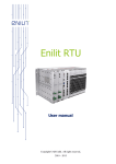
device driver layer between the operating system and the DAQ boards, described below. Fig
3.1 [1] shows the relationship between LabVIEW, NI-DAQ and the DAQ hardware.
Win95 Configuration
LabVIEW for Windows
NI-DAQ Configuration Utility
DAQ Library VIs
DAQDRV
NI-DAQ for Windows 95
Windows 95 Registry
DAQ Board
)LJ'DWD$FTXLVLWLRQ0RGHO
5
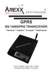
$'$4%RDUGLVD3&,FDUGIRUFRQQHFWLQJH[WHUQDOPHDVXULQJDQGRUFRQWUROOLQJGHYLFHV
WRDFRPSXWHU7KHGHYLFHZHDUHXVLQJLVFDOOHGWKH'$46LJQDO$FFHVVRU\ZKLFKLVXVHGIRU
GHPRQVWUDWLQJ3&EDVHGGDWDDFTXLVLWLRQDQGFRQWURO6HH)LJ>@
)LJ'$46LJQDO$FFHVVRU\
6
0RQLWRULQJ
The goals specified in chapter 2 must be limited and clearly specified. Below are brief
descriptions of the assignment.
•
:KDWLVWREHPHDVXUHG"
•
Temperature and Noise
:KHQLVGDWDVDPSOHG"
•
User specified logging and screen update interval.
:KHUHGRHVPRQLWRULQJWDNHSODFH"
-
Measurement in the same room as the computer, since the cable to the DAQ Signal
Accessory measures only about one meter.
•
Logging unto user specified file path.
:K\PRQLWRU"
-
Measurement to demonstrate simple monitoring.
-
Logging to be able to view old data.
•
+RZWRPRQLWRU"
-
With a LabVIEW user interface and instruments.
-
With a DAQ Board and DAQ Signal Device connected to a PC.
-
With a Web Server for remote survey.
-
With a Message Service for alarm purposes, and possibly remote controlling.
7
)XWXUH$SSOLFDWLRQV
Since the outcome of this project is for demonstration purposes only, no extra features are
added to the system. In the future, however, several applications can be thought of, for
example:
•
Analogue measure of temperature inside and outside the house.
•
Analogue measure of humidity, again inside and outside the house.
•
Digital measure of alarm status (on/off?), and control of this.
•
Digital measure of coffee-machine status (on/off?), and control of this as well.
•
Control of lighting remotely.
•
A variety of other applications.
8
/DE9,(:,QWURGXFWLRQ
LabVIEW does not differ much from any other modern program development environment
like C/C++ or BASIC, except for one important aspect. Other programming languages use
text-based source code. In LabVIEW, the programmer uses a completely graphical language,
G. Programs are created as block diagrams and are called Virtual Instruments (VIs). As any
other programming language, LabVIEW comes with extensive libraries of functions to be
used for (almost) any kind of program. LabVIEW has libraries for data acquisition, analysis,
presentation and storage etc. Also included are tools for setting breakpoints, viewing the data
flow while running the program and run-time stepping to make debugging and program
development easier.
Though LabVIEW is a general-purpose programming system, LWLVGHVLJQHGVSHFLILFDOO\IRU
.
GDWDDFTXLVLWLRQDQGLQVWUXPHQWFRQWURO
The reason why LabVIEW programs are called virtual instruments is because their
appearence and functionality can imitate that of an actual instrument. This is why TietoEnator
has chosen LabVIEW for this assignment.
A VI consists of three different parts:
•
An interactive user interface called the front panel. This simulates the panel of a real
physical instrument. It can consist of knobs, buttons, graphs, and a lot more controls
and indicators. Data can be entered by keyboard or by mouse and the results are shown
via some indicator, like a text-field.
•
A dataflow diagram, which is similar to the source code in a text-based programming
language. This block diagram is constructed in G and provides a graphical solution to
the programming problem.
•
Icon connections are used to specify what inputs and outputs the VI should have, so the
instrument can be used from other VIs.
A VI is hierarchical and modular. This means that you can use them either as top-level
programs or as subprograms within other VIs. A VI used as a subprogram is called a sub-VI.
9
With these features, LabVIEW can really be called a modular language. When
programming in LabVIEW you usually divide your problem into smaller and smaller parts
until there remains only a series of small and simple subtasks. Then you build a VI for each
subtask and combine these in another block diagram to accomplish the larger task. In the end
you have a top-level VI which is the final application.
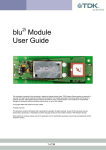
Here comes a simple example of a LabVIEW VI, 7KHUPRPHWHUYL.
1
2
)LJ)URQW3DQHO
3
4
)LJ'DWDIORZ'LDJUDP
Solid proof for the age-old theorem ‘0,24*100,00 = 23,59’.
1. ReadVolts Demo SubVI generates (in some manner) a value, with indata 1 and 0, 0,24.
2. The value is multiplied with 100,00 => 23,59.
3. Temp Scale is set to “deg C” so the result of C->F (Celsius to Fahrenheit) is not used.
4. Temperature is displayed, 23,59.
10
6\VWHP'HVLJQ
This system will consist of three parts, namely the LabVIEW Core, the Message Handler
(with or without SMS) and the Web Server. Since SMS functionality is more or less an
investigation only, we cannot specify exactly how it will work, nor can we guarrantee that it
will. Any solutions in this field will be added to the model as the project proceeds.
7KH/DE9,(:&RUH
LabVIEW is used for measuring from a DAQ Signal Accessory, connected to a PC with a
DAQ Board. Data is acquired and processed within the VIs and SubVIs. The data is then
presented in one or more panels. Also see chapter 4. A window hierarchy will be used, see Fig
5.1.
)LJ6\VWHP6XUYH\
Main Menu
Preferences
Monitor
View old data
Main Menu
Menu with the alternatives below.
Preferences
System settings.
Monitor
Monitoring.
View old data
Logging analyser.
Quit
Exit application.
7DEOH3DUWVRI6\VWHP6XUYH\
11
Quit
0HVVDJH+DQGOHU
Preferably, two-way message communication with a cellular phone is used. A solution for
both sending alarms and receiving commands to and from the LabVIEW Core. This is an
investigation, and depending on the result different functions will be added. This will be
documented later in section 7.1. Another alternative could be sending simple e-mails
(6HQG0DLOYL), which of course is easier to accomplish, since the Internet Toolkit for
LabVIEW has this functionality. When controlling though, SMS would seem slightly more
convenient. The controller may not want to take his computer everywhere. The cellular phone
is always at hand.
When relevant events occur in the LabVIEW Core, see section 8.2, the Message Handler
will be handling these. Depending on the settings, and, of course, the results of our SMS
investigation, messages may be sent to an alarmee (6HQG0DLOYL & 6HQG606YL). The alarmee,
if able to, can also send messages to the Message Handler (*HW0DLOYL). This is not only for
controlling purposes, as it can be used for requesting current data as well. The LabVIEW Core
will regularly check with the Message Handler for incoming commands from the controller
and handle these according to a pre-specified manner.
:HE6HUYHU
The Internet Developers Toolkit for G will be used. It includes the G Web Server, which
can present VIs as web pages, with or without interaction. Technically, this works as a CGI,
to which we
FRXOG
send information such as pressing a button or turning a knob. There are
two solutions for this, either a frame-oriented page or an image map, any will do. Note though
that the VI runs much smoother on a Netscape Navigator browser, where much less flickering
occurs (than in Internet Explorer, that is). Controlling is not the issue here though, because the
viewer is only supposed to watch the monitoring.
12
6\VWHP$UFKLWHFWXUH
Here is an explanation of the integration of the parts mentioned above. LabVIEW Core
might be a misleading term, since all parts are made in LabVIEW. The term was however
named before we knew this could be realized. What is named Core is mainly the menu
structure and the monitoring instruments (as well as review old data). The Web Server is a
prefabricated instrument controlled either from the Core, or from the LabVIEW scroll-down
menu (under Project->Internet Toolkit, accessible through any VI). The Message Handler is
only used from the Core (in monitoring mode), and is an automatic feature, if enabled.
Message Handler is an instrument, consisting of its own “core” and subfunctions for
communicating with the hardware and sending and receiving messages.
Web Server
Core
Message Handler
GetMail
SendMail
Monitor
SendSMS
Legend
Message passing
Using
Part of
)LJ$UFKLWHFWXUH
13
8VHU±6\VWHP,QWHUDFWLRQV
/RFDO,QWHUDFWLRQV
Here we will discuss what the user can do with the front panel of our application. As seen
above in section 5.1: ”The LabVIEW Core,” a menu structure is used. The user presses
buttons (with a mouse) or enters values in text fields (with a keyboard, or maybe a mouse).
Every window will be descibed separately.
:HOFRPH
The user starts the program here, pressing Menu button. See B.1.
0DLQ0HQX
Four buttons: Monitor, View Old Data, Preferences and Quit. When the user selects from
the first three, a new window will pop up (with selected contents). The Quit button, of course,
quits the application. See B.2.
0RQLWRU
Four buttons with LEDs: these are booleans showing the current state. A lit LED means
true and an unlit means false. The buttons are Noise Logging, Temperature Logging, Noise
Alarm and Temperature Alarm. When the user selects one of these, it toggles and logging or
alarm is turned on or off. One button is controlling the HTTP Server, not seen in the
screenshot. When the button is pressed the HTTP Server starts. When unpressed, the server is
stopped. Finally, one Exit button for quit monitoring. The user can also set the axis values of
the charts, by editing these (must turn off Autoscale first though). See B.3.
9LHZ2OG'DWD
Text-fields for specifying date and time interval to review. The possibility to choose noise
or temperature is done with a toggle switch. The “Go!” button reads data from disk and
presents a chart of this data to the user. The scaling is also adjustable with textfields. The Exit
button exits the window. See B.4.
15
3UHIHUHQFHV
Text-fields for altering global settings for the program. Save button saves changes to
memory and disk, and closes window. Cancel exits without saving. See B.5.
5HPRWH,QWHUDFWLRQV
:::
The project specification clearly states
. From a sheer
QR LQWHUDFWLRQ RQ WKH ZHE SDJH
security oriented point-of-view this is quite logical, since
DQ\RQH
DQ\RQH
can view a web page. This
is however not supposed to control our application. Password protection is an
alternative and if TietoEnator wants this they can add this later on. If so, the G Web Server, as
already described, supports interaction through CGI. For now, only a continuosly running
view of Monitor.vi is displayed (if active, that is).
0HVVDJLQJ
As with WWW, messaging is insecure, but not as accessible. We have not added
authentication to the messages, but this can be added later. Controlling is possible only
through email for now, as described in the next chapter, 7.
16
0HVVDJLQJ6HUYLFH
,QYHVWLJDWLRQIRU606)XQFWLRQDOLW\
$ERXW606
The following text is a good description of SMS, translated from Swedish, see ref. [8].
“One of the most interesting functions in the GSM standard is SMS. SMS uses available
time in the control channels from the base stations to inject messages. These messages can be
of any format, but with a maximum length of 160 characters. SMS messages are shown in the
mobile phone’s display, and can be read and written by pressing the telephone’s keys. Even
though the function is useful, it is limited. Connected to a computer with a keyboard, SMS is
an efficient and very useful messaging system.
SMS, which is an additional advantage of the GSM standard, besides data and fax, offers:
•
160 characters long messages.
•
Guarranteed delivery.
•
Acknowledgement of delivery.
•
Receiving and sending can be done during a telephone conversation.
•
Individual or group sending.
How are these advantages useful? The first area of use is messaging. SMS can send
messages to any mobile phone. If the phone is turned off, the message is saved by the operator
and is sent as soon as the phone is turned on. When the message has been received it is saved
in the phone’s SIM card. The receiver can choose when and how he wants to read the
message.
17
To make SMS messaging more efficient you can connect your phone to a laptop or desktop
computer. Messages can then be written from the keyboard, which simplifies the usage of
SMS. They can be sent from a computer with common communication software. For simple,
short messages there are gateways, that translates SMS to fax so the message can be sent to a
fax machine instead. They can also be sent to e-mail adresses. The only limit is 160
characters, which in the example above also must include fax number or e-mail adress.
SMS is becoming more frequent in using to prescribe on information services such as
weather’s forecast or stock exchange ratings. The information can be ordered or automatically
transmitted with wanted time interval.
The presentation of the information is today adapted for the phone’s display. But as the
connections to laptop computers gets more common, these services will become even more
sofisticated. In today’s standard software, SMS is an excellent tool to send short messages.
Alternatively, SMS can be a low cost option for data transmission.”
606,QYHVWLJDWLRQ5HVXOWV
The application we are to develop needs some kind of alarm feature. An alarm must be
instantly read by the alarmee, therefore SMS suits this particular task excellent. One could
think of the corporate manager having vacation on some tropical island and then suddenly a
fire breaks out at his office. He just might want to be aware of this immediately! What then is
needed adding this kind of functionality to the application? What is also needed for adding the
possibility for the user (manager or not) to control the application remotely by his/her phone?
We will try to answer these questions in this chapter.
There are two plausible answers for both questions, either to use an available software
package or to develop SMS functionality. Since
for
XV
ZH
are only investigating, the main purpose
is to track down, test and evaluate available applications. If none would prove suitable,
TietoEnator might have to develop something of their own for SMS. Further below is found
descriptions of software found on the Internet, shareware or freeware, or other commercial
products tested.
18
Also needed is some kind of messaging hardware device. Since SMS is mainly a GSM
phone feature such a phone would be useful. The plan was to use a Nokia 8210, supplied by
TietoEnator. A description of the phone is found at Nokias web site [7].
Since the target environment uses Windows 95, infrared support must be added to the
operating system, as well as an infrared adapter. Infrared support is achieved through the
Infrared Monitor, downloadable for free from Microsofts webpages. The external device in
use is a SIR Infrared Adapter IR Mate IR-210B for Desktop PC. We will not discuss the
technical aspects of this product, because it is not important. (It works therefore it is good).
6RIWZDUH
Nokia has developed a software package for this particular phone called
³3& 6XLWH IRU
, which has some SMS functionality. It works great, really, however there is no
1RNLD ´
way for us to communicate to and from the PC Suite from an external application, which we
must do in order to handle these in LabVIEW. The messages received by the phone are
displayed nicely on the screen, but cannot be saved to disk (and thus not read by any other
programs), nor is there any DDE or OLE support, which would enable communication with
other programs. This software package is thus
QRW
suitable for our needs, to send and receive
messages from another program. We did however find some other software packages,
described below.
•
, which in Europe is called
3DJHU &HQWHU
606 &HQWUH
, both work alike and is just the
same program with different settings for different network providers. Both are
shareware, with evaluation time. However this is not a suitable product, since Pager
Center is designed for North American market and SMS Centre for United Kingdom
market. Even if a special solution for Sweden is arranged, currently supported network
providers are listed in [9], the software is limited for sending SMS only. A nice feature
though is the ability to communicate with the software from other programs, through
the built-in API or command line arguments.
19
•
606 *DWHZD\
[10], which is supposed to manage all wanted features, to send and
receive messages with a phone connected to the computer. However there are no
default settings for the Nokia 8210, which we
GLG
manage to communicate with, but
never in a correct way. The phone was responding, but we didn’t know the correct
settings* (if any) to establish a lasting connection. If another (supported) telephone is
used this application would be just what we’re looking for. It has built-in DDE and
OLE support, which LabVIEW loves. Virtual Instruments could be programmed for
alarm and remote control using a GSM phone. Unfortunately, since we had no such
phone available we have not done these. They would, however, not be too complicated
if and when such a phone is available. Another drawback (besides us not having a
supported phone) was the severe impact on system performance, the computer was
“glued”. This is maybe related to the communication problems we experienced with
our phone.
•
[11] has support for VHQGLQJ messages through DDE, and saving
7'.*OREDOSXOVH
messages from phone. However, this saving procedure is manual and unfortunately
that’s not appreciated from our point of view. Also it did not seem to work with the
specific phone, we suppose due to lack of IR connectivity support.
•
0HVVDJH 0DVWHU 3HUVRQDO
[12] has lots of features, including support for sending and
receiving short messages and built-in support for all Swedish network providers. It has
furthermore support for communicating with other software applications, and with
mobile phones through the infrared port. Like SMS Gateway, described above there are
lots of pre-defined settings for several phones, although, again, not for
RXU
phone. Of
the software listed here we would recommend TietoEnator to have a further look at this
one. With the right phone, from the list below, there is enough to add SMS alarm DQG
control features to this virtual instrument for control and survey of a remote building.
NB. This is almost the same list as that for SMS Gateway.
*
Without being too technical, these settings are in low-level hardware terms, such as ETSI Block/PDU Mode
and Interface Initialization Strings.
20
Ericsson SH888
Falcom A1
Falcom A2
Nokia Card Phone 1.0
Nokia Cellular Data Suite
Nokia Communicator 9000
Nokia Communicator 9110
Nokia Data Card
Option FirstFone
SAGEM MC 850
Siemens M1
Siemens M20
Siemens SL10
UbiCom GSM Modul 232
WAVECOM
7DEOH6XSSRUWHG3KRQHVLQ0HVVDJH0DVWHU
&RQFOXVLRQV
Although we use Nokia Cellular Data Suite for the Nokia 8210, it did not make any signs
of contact (with the program). So, with the “correct” phone, what are the procedures for
adding SMS support to the application?
First, we need to write VIs for sending and receiving messages through the DDE Server
provided by Message Master. Second, a uniform format for messages must be described. For
instance, “TEMPLOG ON” might trigger the temperature logging. More of this in chapter
8.2: “Events in the LabVIEW Core.” The alarm messages are not as strict and are set in the
application preferences. Third, the program core needs to regularly check the phone (Message
Master) for new messages and interpret these and act according to them.
All of the (useful or not) applications above are designed for use with mobile phones,
which is a must when receiving messages. For sending purposes only, there are other
solutions. One of which is a common modem, and a nice application with command line
arguments, called
4XLFN606
[13], with which we actually made a virtual instrument for
sending messages, see screenshot. This VI could easily be added to the Messaging Service of
the whole application.
21
Another solution is to use an online service and some work-around tricks for the login
procedures on the webpages, but that’s not a very smooth way and it will stay a thought. Also
is the possibility to send SMS to e-mail addresses (and vice versa). Though we didn’t find any
services for this, we recommend TietoEnator to do more research in this area, as it could be
useful in combination with our e-mail functionality, see next chapter.
2WKHU0HVVDJLQJ6HUYLFHV
$ERXW(PDLO
Sending away letters over computer networks (usually
HOHFWURQLF PDLO
or briefly called
) is the most wellknown and commonly used communication service on computer
HPDLO
systems. Today, millions of people have the possibility to use email and the popularity of this
service grows day by day. Email offers some advantages in relation to classical
communication: YHU\IDVW, LQH[SHQVLYH and VLPSOH.
For sending messages, an SMTP server is used. These normally respond to the TCP port 25,
and every domain with self-respect has one. Receiving messages can be done through
different techniques, although the most common (and most insecure) is the POP3. These
servers are usually on TCP port 110.
22
(PDLO6HUYLFHLQWKH$SSOLFDWLRQ
As seen in section 7.1, messaging is to be used for alarming and controlling purposes.
Messaging is ideal for the purpose of receiving commands since we can regularly check for
email with the application. Email messaging is not, however, efficient for alarming purposes.
The alarmee might not check his email every minute.
The email service will, seen from the outside, work like the SMS service. The Message
Handler (0HVVDJH +DQGOHUYL) will be invoked from the LabVIEW Core at specific events,
such as checking for commands (mail in this case) or sending alarms (in this case, also by
mail). Settings for which messaging system to be used will be regulated in the preferences.
The email service knows which addresses to use, i.e. for destination and servers, as well as
username and password for the user account. These settings are global variables also
controlled in the preferences.
Communication will be performed through the subject field of the message header.
Explanations of the syntax of this communication will be discussed in section 8.2.2,
“Communication Syntax” below.
23
6\VWHP(YHQWV
'DWD)ORZ
The DAQ Signal Accessory is quite simple. Without external devices connected to it,
which we do not have, there is not much to measure. We can, however, do a few
measurements.
•
Room temperature, with the built-in thermometer in the DAQ Signal Accessory.
•
There is also the possibility to generate a squareform or sine wave and display this. That’s
not very bound to the problem though, to control and survey a building.
•
Additionally, the DAQ Signal Accessory has input for a microphone, which could be
measured as well, perhaps simulating a noise detector.
•
A set of LEDs can be lit by the user and thus simulating a control.
All measurements will be handled by the LabVIEW core and represented graphically in
LabVIEW as well as on the web page. Control, i.e. an interface where the user can alter
certain objects, such as lighting an LED, may be added to the LabVIEW interface, and
possibly to the web page if password protected. An LED could represent anything, from a
light to a burglar alarm.
These are the possibilities with a DAQ Signal Accessory, and thus what we are supposed
to do: monitoring the Accessory for all possible measurements above.
Data history will be logged to text files, for later querys, such as “Give me the temperature
from 2:00pm to 3:00pm the 23rd of May 2004”. This kind of information could be viewed in
LabVIEW or on the web page. Logging will, of course, be performed in a separate VI. More
of this and the other VIs in the subsystem design will be discussed in section 9.2.
25
(YHQWVLQWKH/DE9,(:&RUH
3RVVLEOH(YHQWV
Events are bound to timers. The LabVIEW Core,
, consists of timers regularly
0RQLWRUYL
triggering different events. These are discussed below.
•
The monitoring timer is used for updating the temperature and noise charts with data
acquired from the DAQ Board and Signal Accessory. This is done every second, not
changeable by the user. Alarm checking is made with the same interval. If an alarm
occurs an LED is lit on the front panel showing this. The Message Handler is also
invoked with the alarm as indata.
•
A timer for mail (and/or SMS) checking is used in order to invoke the Message
Handler without indata (actually, isAlarm is set to ‘false’). Message Handler then
checks for mail and returns commands from these mails. Preferably this is performed
every minute. The syntax for interpretating these are descibed below in section 8.2.2.
•
Two timers are used for logging, one for temperature and one for noise. The values of
these are from the preferences set by the user.
&RPPXQLFDWLRQ6\QWD[
Both email and SMS (at least, in theory) can be used for controlling, but how? We need
some way to describe commands. We decided to use the subject field of an email for this
purpose and thus we can use the same syntax for email and SMS controlling. The possible
controls (for now) are listed below.
Command
Description
SET TEMPLOG ON/OFF
Toggles temperature logging on or off.
SET NOISELOG ON/OFF
Toggles noise logging on or off.
SET HTTPSERVER ON/OFF
Starts or stops webserver
GET NOISE
Requests for current noise value, the core then sends this as an alarm message.
GET TEMP
Requests for current temperature value, the core then sends this as an alarm message.
7DEOH&RPPXQLFDWLRQ6\QWD[
26
'HWDLOHG6\VWHP'HVLJQ
6\VWHP$QDO\VLV
Here we will discuss the data flow to, and from functions in use. The LabVIEW
environment is based on “data flow,” and the components, called virtual instruments, can
accept indata as well as generate outdata. These are represented as connectors and will be the
parts focused on here.
Welcome.vi
displays a “welcome message.”
Menu.vi
displays the “Main Menu” of the System Survey
Monitor.vi
monitors temperature and noise, the “Monitor” of the System Survey.
Preferences.vi
handles all globals.
Olddata.vi
displays the “View Old Data” of the System Survey.
Templogger.vi
timestamps and saves current temperature value.
Noiselogger.vi
timestamps and saves current noise value.
LoadPrefs.vi
loads preferences from disk.
SavePrefs.vi
saves preferences to disk.
GetSeconds.vi
auxiliary date/time-string-to-seconds instrument.
MessageHandler.vi
sends and receives messages.
GetMail.vi
retrieves the first mail subject from POP server (if any).
SendMail.vi
sends mail with indata message as subject to specified destination.
SendSMS.vi
sends SMS with indata as message to specified GSM number.
globals.vi
used for data passing between virtual instruments.
7DEOH9,VLQXVH
27
0HVVDJH3DVVLQJDQG*OREDO9DULDEOHV
As seen in table 9.1, there is not much in- or outdata from the virtual instruments, this is
mainly for esthetical purposes. All wiring makes the code unreadable, see B.6 (an early
version of the
). Therefore, we are using global variables to the greatest extent
0HQXYL
possible. There are however a few cases where message passing is more necessary:
•
When certain help functions, such as
*HW6HFRQGVYL
are used, when the data is meant
for use only inside the function.
•
When indata can be different, such as in
, when the message alternates
6HQG0DLOYL
depending on which alarm is to be sent.
VI
Indata
Outdata
Welcome.vi
N/A
N/A
Menu.vi
N/A
N/A
Monitor.vi
N/A
N/A
Preferences.vi
N/A
N/A
Olddata.vi
N/A
N/A
Templogger.vi
N/A
N/A
Noiselogger.vi
N/A
N/A
LoadPrefs.vi
N/A
N/A
SavePrefs.vi
N/A
N/A
GetSeconds.vi
Date – string {YYYY-MM-DD}.
Seconds – uint, since 1904-01-01 00:00:00.
Time – string {HH:MM:SS}.
MessageHandler.vi
Alarm command - string
Control command – string
IsCommand – boolean
GetMail.vi
N/A
Command – string
SendMail.vi
Alarm – string
N/A
SendSMS.vi
Alarm – string
N/A
Globals.vi
N/A
N/A
7DEOH'DWDIORZWRDQGIURPWKHLQVWUXPHQWV
,QVWUXPHQW,QGLYLGXDOLW\
As mentioned before, the globals.vi will be in use, connecting the various instruments as a
whole. This reduces modularity. Furthermore, it is not completely safe trying to run for
example
0RQLWRUYL
without first loading the preferences.
0RQLWRUYL
needs to know certain
things about the measuring hardware mentioned in these settings and may otherwise generate
unwanted errors.
28
6XEV\VWHP$QDO\VLV
Here we discuss the mechanisms within each subsystem. The conditions for invoking
other virtual instruments and detailed discussion on functionality.
:HOFRPHYL
The purpose of this instrument is plainly to be a “start”-page of the application. Here
settings will be loaded into memory, to
, from disk, if previously saved. When the
JOREDOVYL
user so desires the 0HQXYL will be loaded when pushed the “Menu” button. See B.1.
0HQXYL
This consists of a loop, which waits for the “Quit” button to be pressed. Meanwhile the
user can start the different subsystems from here:
,
0RQLWRUYL
2OGGDWDYL
and
,
3UHIHUHQFHVYL
each one connected to a button, quite self-explainatory. See B.2.
0RQLWRUYL
First, two charts, one for temperature level monitoring and one for noise level monitoring
is initialized to the current time, this is achieved by invoking the
*HW6HFRQGVYL
with the
current date and time. The charts are set to display the last 300 seconds. A chart update timer
value is set from JOREDOVYL.
Second, measuring is started. Logging and alarm can be turned on and off while
measuring. If temperature logging is turned on (controlled with an LED button), every
“temperature logging interval milliseconds” from
preferences), the
7HPS/RJJHUYL
JOREDOVYL
(preferably set in the
will be invoked. The same goes for noise logging and
. Temperature is being averaged over a specific number of readings, from
1RLVH/RJJHUYL
, this in order to reduce faulty spikes and for nicer plotting.
JOREDOVYL
While measuring, alarms may occur. These show themselves as LEDs on the screen and
possibly as alarms to Message Handler. Eventually, the Message Handler is checked for
remote commands. Indata to Message Handler (alarm message) is set to empty string that
indicates no alarm.
29
Looking at B.3 we first notice the two graphs (charts) showing the last five minutes of
monitoring temperature and noise. Noise is above, temperature below. The thermometer
shows current temperature. Beside the charts, LEDs are lit if alarm, but only if the alarm
buttons on the right are active (lit). The alarm button LEDs on the right also enables/disables
alarms through Message Handler. The logging button LEDs toggles logging of monitoring
data to disk. In this example, both the alarms and logging of noise are on. This would have
resulted in a “Fire!” message (or what is specified) through mail or SMS if enabled by user.
2OGGDWDYL
This instrument does not perform anything until the user presses the “Go!” button. The
user specifies a time interval with the “from” and “to” text-fields. Also specified is type of
data and zooming interval on the y-scale. Values, within the specified date/time interval, are
loaded from a file, specified in JOREDOVYL, and sent to initialize a “XYchart”. Values are stored
in the form of [DATE][tab][TIME][tab][VALUE][end of line]. The date and time values are
being converted to seconds with the *HW6HFRQGVYL. Each time and logged data value is sent to
the XYchart. The chart displays a curve of the specified interval. See B.4.
30
3UHIHUHQFHVYL
This instrument consists of text fields, where the user can edit settings. If “Save” button is
pressed these are stored in
JOREDOVYL
and then the
6DYH3UHIVYL
is invoked. The “Cancel”
button exits preferences without updating or saving. See: B.5. Table 9.3 describes the settings
that are used in this VI.
Limits
Channels
Logging
E-mail
SMS
Alarm
Get
Send
Max Temp
The limit when temperature is too high, for “heat alarm”.
Min Temp
The limit when temperature is too low, for “chill alarm”.
Max Noise
The limit when noise is too high, for “noise alarm”.
Temp Channel
The channel on the DAQ Board for temperature measurement.
Microphone Channel
Same as above, but for noise measurement.
Alarm Lamp
A value for the LEDs on the DAQ Board, not really a channel.
Temp Logging Interval
How frequent temperature data is saved to disk (ms).
Temp Logging Filename
The disk location to save temperature data.
Noise Logging Interval
How frequent noise data is saved to disk (ms).
Noise Logging Filename
The disk location to save noise data.
POP Username
The login name to the POP3 server.
POP Password
The password to the POP3 server.
POP Server
The host name or IP address of the POP3 server.
SMTP Server
The host name or IP address of the SMTP server.
Destination Adress
The email address of the alarmee.
Checking Interval
How frequent email checking is done.
Phone no
The GSM number of the alarmee.
QuickSMS
The file path to the QuickSMS software executable.
Max Temp Message
Message received by an alarmee when “heat alarm” occurs.
Min Temp Message
Same as above, for “chill alarm”.
Max Noise Message
Again, as above, for “noise alarm”.
Email
Checkbox, should we check for email commands?
SMS
Checkbox, should we check for SMS commands? (for future purposes)
Email
Checkbox, should we send email alarms?
SMS
Checkbox, should we send SMS alarms?
7DEOH3UHIHUHQFHV
7HPSORJJHUYLDQG1RLVHORJJHUYL
These are treated together since they act similarly. The requested type will get actual data
value and logging filename from JOREDOVYL, set by the monitoring instrument and preferences.
They are atomic actions, where we open-write-close the file in one transaction. The current
date/time
is
stored
together
with
the
current
value
[DATE][tab][TIME][tab][VALUE][end of line] for easy reading.
31
in
the
form
of
/RDG3UHIVYL
Preferences will be restored from a preferences file, name specified in
. The
JOREDOVYL
formatting will be [VALUE][end of line] for each setting. These are in turn loaded from the
file and stored in JOREDOVYL.
6DYH3UHIVYL
It is the complete opposite of LoadPrefs, yet very similar. Preferred values in
JOREDOVYL
will be saved to the preferences file.
*HW6HFRQGVYL
Splits the indata strings, date and time, to separate integers for year, month, day, hour,
minute and second, converts to seconds with a built-in LabVIEW VI named “Date/Time to
Seconds”. Returns the seconds as outdata to a calling instrument.
0HVVDJH+DQGOHUYL
First, checks the indata Alarm, a string value. If not empty (we check this inside Message
Handler), then we are dealing with an alarm. Alarm mail and/or SMS can be sent to userdefined address and/or phone number, if enabled. This is realised using
6HQG0DLOYL
and/or
with alarm message.
6HQG606YL
If the indata is empty, then we are
QRW
dealing with an alarm. Intead we check for email,
using *HW0DLOYL, (and/or SMS if possible).
The instrument has an outdata parameter called isCommand, which is boolean. If mail (or
SMS) is retrieved the command is extracted and returned. To mark that a command is
retrieved, isCommand is set to true, otherwise it is set to false. The isCommand parameter is
for outside use, putting the command check inside MessageHandler and thus saves
(LabVIEW) programming space outside MessageHandler.
*HW0DLOYL
Logs onto a POP3 Server, using an add-on package called POP, found on National
Instruments web page [14], with username and password from preferences. Retrieves the first
message. Returns the subject line of this message.
32
6HQG0DLOYL
Gets indata message, then logs on to a SMTP Server, using the Internet Toolkit SMTP
instruments, and sends the message to the destination address specified in preferences.
6HQG606YL
Uses the external program QuickSMS, discussed in section 7.1.2: “SMS Investigation
Results”. Gets indata message, then invokes QuickSMS through command-line parameters
with phone number from preferences and message.
*OREDOVYL
A global variable is a built-in G feature. When you create a global variable a special kind
of VI is automatically created. You can either write to or read from a global variable. Writing
to a global variable means the value of the global changes; reading from a global means you
access the global as a data source. Global variables can be written and read by any VI in
memory. The global variable (the VI) can hold many variables, much like a struct or record in
other languages. Different global variables (VIs) can be used, we do not however use more
than one.
“Global variables store data used by several VIs. Use global variables judiciously because
they hide the data flow of your diagram. Although you need global variables in some
applications, do not use them if you can structure your program using an alternate data flow
method for transferring data.” [3]
Thus spoke the experts. We, however, find global variables
YHU\
useful in this particular
assignment. Of course, we could use message passing to and from the VIs, but this would
VHYHUO\
decrease readability and creates a tangle of wires not at all pleasing to the eye. Extra
caution is taken not to mess things up, not using global variables in suspicious places resulting
in race conditions, i.e. one VI tries to read from a global when another tries to write at the
same time. Since the graphical environment simplifies this, we find it safe using global
variables
33
&RQFOXVLRQVDQG5HVXOWV$QDO\VLV
5HVXOWV$V([SHFWHG"
The goals listed in the section 2.1 will be treated here. Have we done what is expected of
us?
•
We have a fully functional application, running on a computer. We collect data from
inputs and represent them graphically on the computer screen in an appropriate way. The
application is capable of measuring, and the user is capable of controlling the units listed
in the system specification.
•
The application can be viewed on the screen of a PC, using a web browser, preferably
Netscape Navigator, and an Internet connection.
•
We have investigated the necessary steps in adding SMS functionality to the application in
1. We have documented solutions for sending SMS messages when a certain event occurs
and also the capability of sending SMS messages to the computer with commands
controlling the application. Although we did only implement the sending procedures.
Instead we have a fully functioning messaging service for sending and receiving emails.
35
7LPH3ODQ$FFRUGDQFH
We had, as seen in the chart in section 2.3, made a time plan. The question is, did we
follow it? And if so, how accurate? If not, why?
First off, we did not start working until a week after the expected start, therefore the dates
on the plan does not fully match reality. The self-study of LabVIEW took a little longer than
expected. Initially, we did some background reading, then we learned more continuously. The
system specification was finished quite early, nothing much to comment there. The design,
however, was much done in parallell with the coding and testing, since LabVIEW works well
with prototyping.
What we did not include in the time plan was the SMS investigation. This is mainly
because we forgot it at first. It took almost half the period, and was done largely in parallell
with all other events. The documentation has been performed as planned, continuosly.
0DLQWDLQDELOLW\RIWKH6\VWHP
3HUIRUPDQFH
The computer we used in this project, a Pentium 166 (with 96 MB RAM), works, but
would be considered the absolute minimum system requirements. We do not know exactly
how fast a computer is needed. Perhaps a more modern OS would be in place as well (now
running Windows 95).
36
0DLQWHQDQFH
If SMS functionality were to be added to the application, as described in this document, a
demonstrating example of control and monitoring, very well worth its name, could be created.
With the right resources many exciting add-ons could be made,. We hope our program is
modular enough.
The logging procedures are quite diskspace consuming, especially when logging interval is
fairly short. Perhaps some application for cleaning logs is convenient. For example deleting
unneccessary data or maybe for backup purposes. This is beyond our jurisdiction, but keep it
in mind.
)LQDOZRUGV
It was a delightful experience coming in contact with the world of LabVIEW. LabVIEW is
a very comfortable environment for developers who like to see fast results and a good
overview of the coding. On the other hand, it makes you lazy and when you change to a more
low-level kind of language you wonder where all those fancy features have gone.
Finally, thanks to TietoEnator for these months. It’s a nice place with nice people.
37
5HIHUHQFHV
[1] National Instruments Corp., LabVIEW Basics I Hands-On Course, National
Instruments, 1998.
[2] National Instruments Corp., LabVIEW Function and VI Reference Manual,
National Instruments, 1998.
[3] National Instruments Corp. LabVIEW User Manual, National Instruments, 1998.
[4] National Instruments Corp. G Programming Reference Manual, National Instruments,
1998.
[5] National Instruments Corp. LabVIEW Data Acquisition Basics Manual, National
Instruments, 1998.
[6] National Instruments Corp. DAQ Signal Accessory, User Guide, National
Instruments, 1996.
[7] http://www.nokia.com/phones/8210/index.html, 2000-06-06.
[8] http://www.communica.se/kunskapsbank/gsm_data.htm, 2000-06-06.
[9] http://www.desoft.co.uk/network2.html, 2000-06-06.
[10] http://www.winsms.com/, 2000-06-06.
[11] http://www.tdksys.com/Products/softmob/index2.htm, 2000-06-06.
[12] http://www.derdack.com/products/, 2000-06-06.
[13] http://qsms.ultraaccess.net, 2000-06-06.
[14] http://www.ni.com, 2000-06-06.
39
$ $EEUHYLDWLRQV
BASIC
%
eginner’s $ll-purpose 6ymbolic ,nstruction &ode
CGI
&
DAQ
'
DDE
'
ETSI
(
G
The *raphical Programming Language
GSM
*
I/O
,
IR
,
LabVIEW
/DE
LED
/
MB
0
NB
1
NI-DAQ
1
OLE
2
OS
2
PC
3
PCI
3
PDU
3
POP3
3
RAM
5
SIM
6
SIR
6
SMS
6
SMTP
6
TCP
7
VI
9
ommon*ateway,nterface
ata $cTuisition
irect 'ata (xchange
uropean 7elecommunications 6tandards ,nstitute
lobal 6ystem for 0obile Communications nput2utput
nfraUed
oratory 9irtual ,nstrument (ngineering :orkbench
ight(mitting'iode
ega%yte
otaEene
ational,nstruments'ata$cTuisition
bject /inking and (mbedding
perating6ystem
ersonal &omputer
eripheral &omponent ,nterconnect
rotocol'ata8nit
ost2ffice3rotocol
andom $ccess 0emory
ubscriber ,dentity 0odule
ustained ,nformation 5ate
hort 0essaging 6ervice
imple0ail7ransfer3rotocol
ransmission&ontrol3rotocol
irtual ,nstrument
41
% 6FUHHQVKRWV
% :HOFRPHYL
% 0HQXYL
43
% 0RQLWRUYL
% 2OGGDWDYL
44
% 3UHIHUHQFHVYL
45
% 0HQXYL'LDJUDP
46
% 0RQLWRUYLVHHQWKURXJKDZHEEURZVHU
47