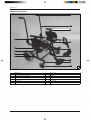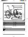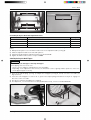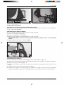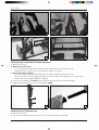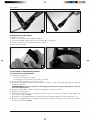
1
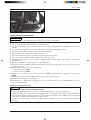
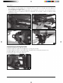
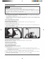
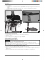
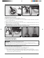
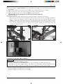
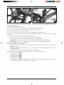
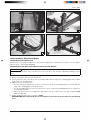
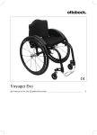
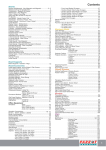
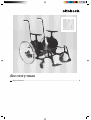
discovery tmax Service Manual ...................................................................................................... 3 2 | Ottobock discovery tmax Table of contents Table of contents 1 1.1 1.2 1.3 Introduction .........................................................................................................................................................5 Foreword ............................................................................................................................................5 Support ...............................................................................................................................................5 Product Overview .................................................................................................................................6 2 2.1 2.2 Safety ....................................................................................................................................................................7 Explanation of Warning Symbols .............................................................................................................7 General Safety Instructions ....................................................................................................................8 3 3.1 3.2 3.3 3.4 3.5 3.5.1 3.5.1.1 3.5.1.2 3.5.1.3 3.5.2 3.5.3 3.5.4 3.6 3.6.1 3.6.2 3.6.3 3.6.4 3.6.5 3.6.6 3.6.7 3.6.8 3.7 3.7.1 3.7.2 3.7.3 3.7.4 3.7.5 3.7.6 3.8 3.8.1 3.8.2 3.8.3 3.9 3.9.1 3.9.2 3.10 3.10.1 3.10.2 3.11 3.11.1 3.11.2 3.11.3 3.12 3.12.1 Service Work .......................................................................................................................................................8 General Information ..............................................................................................................................8 Instructions for Adjustment.....................................................................................................................8 Maintenance Schedule ..........................................................................................................................8 Required Tools and Accessories .............................................................................................................8 Assembly A: Frame ...............................................................................................................................9 Replacing the Adjustment Tubes .............................................................................................................9 Replacing the Adjustment Tubes on the Main Frame .................................................................................9 Replacing the Adjustment Tubes on the Seat Frame ................................................................................10 Replacing the Push Bar Adjustment Tubes .............................................................................................11 Replacing the Anti-Tipper .....................................................................................................................11 Retrofitting the Lashing Points ..............................................................................................................12 Replacing the Back Plates ...................................................................................................................12 Assembly B: Footrest ..........................................................................................................................13 Adjusting the Foot Rests/Tube Foot Rest/Foot Plates ..............................................................................13 Replacing the Footrest Adapter ............................................................................................................13 Replacing the Footrest.........................................................................................................................13 Replacing the Foot Rest Bar/Swivel Segment .........................................................................................14 Replacing the Pivot Bearing .................................................................................................................14 Replacing the Locking Device ..............................................................................................................15 Replacing the Footplate .......................................................................................................................15 Replacing the Heel Band .....................................................................................................................16 Assembly C: Seat/Seating System ........................................................................................................16 Replacing the Locking Plate .................................................................................................................16 Replacing the Locking Unit ..................................................................................................................17 Replacing the Locking Plate Guide .......................................................................................................18 Replacing/Retrofitting the Seat Plate .....................................................................................................19 Replacing/Retrofitting the Seat Plate Supports .......................................................................................19 Replacing the Locking Pedal ................................................................................................................19 Assembly D: Back/Push Handle ...........................................................................................................21 Replacing the Push Handles ................................................................................................................21 Replacing/Retrofitting the Push Bar.......................................................................................................21 Replacing the Back Plates ...................................................................................................................21 Assembly E: Side Panels .....................................................................................................................21 Replacing/Retrofitting the Side Plates ....................................................................................................21 Replacing the Armrest Pads .................................................................................................................22 Assembly F: Caster Wheels .................................................................................................................22 Replacing the Caster Wheels ...............................................................................................................22 Replacing the Caster Fork ...................................................................................................................23 Assembly G: Rear Wheels ...................................................................................................................23 Replacing the Rear Wheels ..................................................................................................................23 Replacing the Wheel Attachments for Wheels with Quick-Release Axle .....................................................24 Replacing the Rear Wheel Adapters ......................................................................................................25 Assembly H: Wheel Lock/Brake ............................................................................................................27 Adjusting the Wheel Lock ....................................................................................................................27 discovery tmax Ottobock | 3 Table of contents 3.12.2 3.12.3 Replacing the Knee Lever Wheel Lock for 12"/16" Wheels ......................................................................27 Replacing the Knee Lever Wheel Lock for 22"/24" Wheels ......................................................................28 4 4.1 4.2 Appendices ........................................................................................................................................................29 Technical Data ....................................................................................................................................29 Maintenance Schedule ........................................................................................................................30 4 | Ottobock discovery tmax Introduction 1 Introduction 1.1 Foreword Regular maintenance is important – it improves safety and increases the lifespan of the product. All Mobility products should be inspected and serviced once a year. However, we recommend inspecting, readjusting, and if necessary servicing the product every 6 months if the product is used frequently, by growing children or by users with changing clinical conditions. Only use original spare parts for all service and maintenance work. The service and maintenance tasks described here should only be completed by trained, qualified personnel and not by the user of the device. This service and maintenance manual refers to the respective spare parts catalogues and the instructions for use of the described products. Please use these documents together. Use the maintenance schedule (checklist) as a template for making copies. Retain completed maintenance sched ules and provide the customer with a copy. discovery tmax Instructions for Use (Qualified Personnel) 647G734=* Instructions for Use (User) 647G733=* 1.2 Support Your national Ottobock team will be happy to answer any technical questions. The contact addresses and tele phone numbers can be found on the back inside cover of the service manual. discovery tmax Ottobock | 5 Introduction 1.3 Product Overview 1 discoverytmax - Version with 12" wheels 1 Main frame 2 Seat frame 8 Caster wheel 9 Footrest 3 Pivot point for angle adjustment 10 Footplate 4 Hole channel for angle adjustments (2.5° increments) 11 Side panel with armrest 5 Locking pedal 12 Back frame 6 Rear wheel 13 Push handle 7 Knee lever wheel lock 14 Lashing point (option) 6 | Ottobock discovery tmax Safety 2 discoverytmax with 22" wheels 1 Main frame 2 Seat frame 8 Caster wheel 9 Footrest 3 Pivot point for angle adjustment 10 Footplate 4 Hole channel for angle adjustments (2.5° increments) 11 Side panel with armrest 5 Locking pedal 12 Back frame 6 Rear wheel 13 Push handle 7 Knee lever wheel lock 14 Lashing point (option) 2 Safety 2.1 Explanation of Warning Symbols WARNING Warnings regarding possible risks of severe accident or injury. CAUTION Warnings regarding possible risks of accident or injury. NOTICE Warnings regarding possible technical damage. discovery tmax Ottobock | 7 Service Work 2.2 General Safety Instructions CAUTION Failure to observe installation instructions Pinching, crushing due to installation errors ► Do not reach between force-actuated surfaces during installation work. CAUTION Use of unsuitable tools Pinching, crushing or damaging the product ► When working, use only tools that are suitable for the conditions at the workplace and whose proper use ensures safety and health protection. NOTICE Tipping or falling of the product Damage to the product ► When you work on the product, secure it so that it cannot tip over or fall over. ► Use a clamping device to secure the product for all work at a workbench. NOTICE Re-use of self-locking nuts Unintended loosening of the screw connections ► Always replace self-locking nuts with new self-locking nuts after disassembly. 3 Service Work 3.1 General Information INFORMATION Read the service manual before starting work. Familiarise yourself with the functions of the product prior to inspection and use. In order to do so, you can request this service manual and other documentation from the manufacturer (see the overview of national Ottobock branches on the inside of the back cover) or download from our homepage www.ottobock.de or www.ottobock.com. INFORMATION Clean and disinfect the product before commencing service work. Observe all care instructions and product-specific inspection instructions in the instructions for use. INFORMATION Many screw connections utilise screws and nuts equipped with thread lock. If you loosen screw connections, be sure to replace the respective nut or screw with one equipped with a new thread lock. If new screws or nuts with thread lock are not available, apply a medium-strength liquid thread locking compound (such as Loctite® 241 or Euro Lock A24.20) to the existing screws. 3.2 Instructions for Adjustment The following chapter describes the replacement and retrofitting of standard and option parts on the product shown on the cover. All instructions concerning the adjustment of the parts installed are included in the Instructions for Use (Qualified Personnel) – see the chapter "Foreword" for the order number. 3.3 Maintenance Schedule Maintenance schedule as a template for copying: see Page 30. 3.4 Required Tools and Accessories The following tools are required in order to perform the service work: 8 | Ottobock discovery tmax Service Work • • • • • • • • • • • • • • • • Reversible ratchet handle wrench and sockets (size: 8 – 24) Torque wrench (measurement range 5 - 50 Nm) Wrench (size: 8 – 24)* Allen wrench (size: 2.5 – 6)** Screwdriver (blade width: 2.5/3.5/5 mm) Phillips head screwdriver (size: 2) Hammer (approx. 300 g); plastic hammer Pliers: cutting pliers, combination pliers, snap ring pliers Rivet gun (for rivets up to ø 5 mm) Pin punch, ø 3/4/5/6 mm Drill/twist drill ø 3.2/5/5.2/6 mm Stanley knife with sickle hooked blade and standard blade Tyre mounting levers and inner tube repair kit* Workbench and vice with plastic jaws and rubber insert Measurement equipment: rule, spirit level Liquid thread locker, "medium" and "strong" * Included in the 481C08=ST010 Tool Set ** Size 3–6 included in the 481C08=ST010 Tool Set 3.5 Assembly A: Frame 3.5.1 Replacing the Adjustment Tubes The adjustment tubes must be replaced in the course of retrofitting seat widths that cannot be achieved with the installed adjustment tubes. To simplify replacement, the main frame and seat frame adjustment tubes should be replaced at the same time. This saves removing the seat frame from the main frame. If the frame width is altered, the width of the push bar also has to be changed (see Page 11). Existing seat plates must be removed in advance. 3.5.1.1 Replacing the Adjustment Tubes on the Main Frame Article Number 471C22=SS021 471C22=SS022 471C22=SS023 471C22=SS024 Adjustment Tube (for front/rear)* Adjustment Tube for seat width 12"–16" / 30–40 cm Adjustment Tube for seat width 14"–18" / 35–45 cm Adjustment Tube for seat width 16"–20" / 40–50 cm Adjustment Tube for seat width 18"–22" / 45–55 cm Quantity 2 2 2 2 * Seat width between the armrests, measured between the lateral guides of the armrest (lateral guides without optional seat plates) 1) Loosen 4 x Allen head screws on each of the adjustment tubes at the rear (see Fig. 3, item 1) and front (see Fig. 4, item 2). INFORMATION: In some cases, the Allen head screws on the locking pedal also have to be loosened (see Fig. 3, item 3). 2) Push the adjustment tubes to the side and replace them one by one. 3) Symmetrically preinstall the adjustment tubes in the desired width. INFORMATION: The connection between the adjustment tube and frame always has to be realised on both sides with 2 Allen head screws + washers (use inner 2 bores). INFORMATION: If required, an asymmetry of 12.5 mm (1/2") is allowable when adapting the adjust ment tubes. The asymmetry must be on the same side on all adjustment tubes. However, the allow able adjustment range must not be exceeded. 4) Retighten all Allen head screws to a torque of 10 Nm. discovery tmax Ottobock | 9 Service Work 3 4 3.5.1.2 Replacing the Adjustment Tubes on the Seat Frame INFORMATION If a push bar is installed, it needs to be replaced at the same time (see the next chapter). Article Number 471C22=SS021 471C22=SS022 471C22=SS023 471C22=SS024 Adjustment Tube (for front/rear)* for seat width 12"–16" / 30–40 cm for seat width 14"–18" / 35–45 cm for seat width 16"–20" / 40–50 cm for seat width 18"–22" / 45–55 cm Quantity 2 2 2 2 Article Number 471D22=SS022 471D22=SS023 471D22=SS024 471D22=SS025 Adjustment Tube (for seat fork/locking mechanism)* for seat width 12"–16" / 30–40 cm for seat width 14"–18" / 35–45 cm for seat width 16"–20" / 40–50 cm for seat width 18"–22" / 45–55 cm Quantity 2 2 2 2 * Seat width between the armrests, measured between the lateral guides of the armrest (lateral guides without optional seat plates) 1) Loosen 4 x Allen head screws on each of the adjustment tubes at the front (see Fig. 5, item 1) and rear (see Fig. 5, item 2). 2) Loosen 2 x Allen head screws with counter nuts on the adjustment tube of the central seat fork (see Fig. 5, item 3). 3) Loosen 2 x Allen head screws with counter nuts on the adjustment tube of the locking mechanism (see Fig. 5, item 4). 4) Push the adjustment tubes to the side and replace them one by one. 5) Symmetrically preinstall the adjustment tubes one by one in the desired width. INFORMATION: The connection between the adjustment tube and frame always has to be realised on both sides with 2 Allen head screws + washers (use inner 2 bores). INFORMATION: If required, an asymmetry of 12.5 mm (1/2") is allowable when adapting the adjust ment tubes. The asymmetry must be on the same side on all adjustment tubes. However, the allow able adjustment range must not be exceeded. 6) Tighten all Allen head screws to the following torque values: → Item 1/2: 10 Nm → Item 3/4: Allen head screw – 8 Nm; counter nut – 10 Nm 10 | Ottobock discovery tmax Service Work 5 6 3.5.1.3 Replacing the Push Bar Adjustment Tubes Article Number 471D22=SS022 471D22=SS023 471D22=SS024 471D22=SS025 Adjustment Tube (for push bar)* for seat width 12"–16" / 30–40 cm for seat width 14"–18" / 35–45 cm for seat width 16"–20" / 40–50 cm for seat width 18"–22" / 45–55 cm Quantity 1 1 1 1 * Seat width between the armrests, measured between the lateral guides of the armrest (lateral guides without optional seat plates) 1) 2) 3) 4) With push bar option: loosen 2 x Allen head screws on the adjustment tube (see Fig. 6). Slide the adjustment tube to the side and replace it. Symmetrically preinstall the adjustment tube in the desired width. Tighten the Allen head screws to a torque of 8 Nm. 3.5.2 Replacing the Anti-Tipper CAUTION Incorrect fitting of anti-tipper / missing anti-tipper Risk of tipping of the user to the rear ► Check correct installation and adjustment of the anti-tipper: ► Depending on the adjustment of the chassis, the wheelchair centre of gravity and the experience of the user, an anti-tipper may be necessary. 1) Press in the tripod spring (see Fig. 7) and pull the anti-tipper (see Fig. 8, item 1) out of the cross tube (see Fig. 8, item 2). 2) Insert the new anti-tipper. In order to do so, push in the tripod spring and allow the front pin to engage in a bore hole on the cross tube. 3) Visually check that the anti-tipper has engaged. 4) For adjustment, see the Instructions for Use (Qualified Personnel), reference number 647G734. 7 discovery tmax 8 Ottobock | 11 Service Work 3.5.3 Retrofitting the Lashing Points WARNING Prohibited installation of parts after an accident Serious injuries due to unidentifiable product defects ► Continuing to use the product after a traffic accident is prohibited. 1) Screw the front lashing points onto the seat frame using the 2 supplied Allen head screws, but do not tighten the screws (see Fig. 9, item 1). INFORMATION: The front lashing points must face to the outside. 2) Screw on the rear lashing points using the back plate mounting screws (see Fig. 10, item 1). Also mount a pin between the rear mounting screws, respectively (see Fig. 10, item 2; see Fig. 11, item 3). INFORMATION: The rear lashing points must face to the inside. 3) Tighten all Allen head screws/mounting screws to a torque of 10 Nm. 4) Attach the "Anchor Point/Fixing Point" sticker to the lashing points so it is readily visible from the outside (no illustration). 9 10 3.5.4 Replacing the Back Plates INFORMATION To adjust the back angle, see the Instructions for Use (Qualified Personnel), reference number 647G734. 1) Loosen 2 x Allen head screws on the back plate/seat frame connection (see Fig. 11, item 1). The rear cross tube on the seat frame does not have to be removed (see Fig. 12, item 1). 2) If a lashing point is installed, also loosen 1 x Allen head screw and 1 x pin (see Fig. 11, item 2). 3) Loosen 3 x Allen head screws on the back plate/push handle connection (see Fig. 11, item 3, 1 x Allen head screw not illustrated). 4) Remove and replace the back plate. INFORMATION:If required, the back plate depth position can be adjusted after loosening the 2nd back plate (see Fig. 12, item 2). 5) Reinstall the back plate. Screw the rear cross tube into place at the same time (see Fig. 12, item 1). 6) Tighten all Allen head screws to 10 Nm. 12 | Ottobock discovery tmax Service Work 11 12 3.6 Assembly B: Footrest 3.6.1 Adjusting the Foot Rests/Tube Foot Rest/Foot Plates All instructions concerning the adjustment of the foot rests are included in the Instructions for Use (qualified per sonnel) – order number 647G585. 3.6.2 Replacing the Footrest Adapter 1) 2) 3) 4) Loosen the Allen head screws on the seat frame (see Fig. 13, item 1). Remove the lashing point if applicable. Remove and replace the footrest adapter. Bring the footrest adapter to the desired position (see Fig. 13, item 2). INFORMATION: Note the minimum insertion depth. The footrest adapter needs to be secured with 2 screws. 5) Tighten all Allen head screws to a torque of 10 Nm. 13 3.6.3 Replacing the Footrest 1) 2) 3) 4) If necessary: open the calf band and disengage it from the holder. Flip the footplate up. Release the footrest locking mechanism (see Fig. 14) and swing the foot rest 90° to the outside (see Fig. 15). Pull the footrest up, remove and replace it. Slide the footrest into the holder on the front frame tube from above (see Fig. 16). The footrest has to face out by 90°. 5) Swing the footrest in until the locking mechanism engages. 6) Fold down the footplate. If necessary: engage the calf band on the holder (see Fig. 17, item 1) and adjust the length of the calf band. In order to do so, open/adjust/close the hook-and-loop closure (see Fig. 17, item 2). discovery tmax Ottobock | 13 Service Work 14 15 16 17 3.6.4 Replacing the Foot Rest Bar/Swivel Segment 1) Remove the footrest. 2) Replace the footrest bar: → Loosen the bottom Allen head screw size 4 on the swivel segment (see Fig. 18, item 1). → Remove the footrest bar from the swivel segment. Replace if required. 3) Replace the swivel segment: → Loosen the bottom Allen head screw size 4 on the swivel segment (see Fig. 18, item 1). → Also loosen and remove the upper Allen head screw size 4 on the swivel segment (see Fig. 18, item 2). → Slide off the swivel segment. Replace if required. 4) Insert the footrest bar at least 40 mm into the swivel segment (see Fig. 19; similar illustration). 5) Tighten the Allen head screws on the footrest bar to 10 Nm. 18 19 3.6.5 Replacing the Pivot Bearing 1) Remove the footrest. 2) Loosen the size 5 Allen head screw at the centre of the pivot bearing (see Fig. 20). 14 | Ottobock discovery tmax Service Work 3) Remove/replace the pivot bearing. 4) Reinstall the pivot bearing. Tighten the Allen head screw to 5 Nm. 20 21 3.6.6 Replacing the Locking Device 1) 2) 3) 4) Remove the footrest. Loosen the size 5 Allen head screw on the locking device (see Fig. 21). Remove/replace the locking device. Reinstall the locking device. Tighten the Allen head screw to 10 Nm. 3.6.7 Replacing the Footplate Standard footrest 1) Loosen the size 5 Allen head screw on the footrest bar (see Fig. 22, item 1). 2) Slide the footplate off the footrest bar and replace it. 3) Tighten the Allen head screw to a torque of 8 Nm. 22 Aluminium footplate 1) Loosen the size 5 Allen head screw on the lower footrest bar (see Fig. 23). 2) Slide off and replace the footplate (see Fig. 24). 3) Tighten the Allen head screw to a torque of 10 Nm. discovery tmax Ottobock | 15 Service Work 23 24 3.6.8 Replacing the Heel Band 1) 2) 3) 4) 5) Remove the footrest. Remove the footrest bar with footplate if required. Unscrew the Phillips head screw on the heel band holder (see Fig. 25). Remove/replace the heel band holder and the heel band. Reinstall the heel band. 25 26 3.7 Assembly C: Seat/Seating System 3.7.1 Replacing the Locking Plate 1) Preparing for installation: → Set the seat angle to 30° or higher. → If required, loosen the wheel lock and slide it to the side. 2) Loosen 3 x Allen head screws (see Fig. 27, item 1). 3) Thread the locking plate between the locking pin (see Fig. 27, item 2) and locking plate guide (see Fig. 27, item 3) and remove it. INFORMATION: If necessary, you have to disengage the locking pin from the locking plate so you can remove the locking plate. 4) Remove the attached pinch protector from the locking plate (see Fig. 27, item 4). 5) Replace the locking plate. 6) Attach the pinch protector to the locking plate with 1 x cap screw + washer (see Fig. 27, item 5). Tighten the cap screw to a torque of 8 Nm. 7) Thread the new locking plate between the locking pin and locking plate guide. The angle marking faces out. 8) Mount the locking plate on the seat adapter with 3 x Allen head screws + washers (see Fig. 27, item 1). Tighten the Allen head screws to 10 Nm. 16 | Ottobock discovery tmax Service Work 27 3.7.2 Replacing the Locking Unit INFORMATION The manufacturer recommends replacing the locking unit as a pair on both sides. 1) Remove the locking plate (see Page 16). 2) Loosen the locking mechanism linkage (see Fig. 28, item 1). 3) Loosen 2 x mounting screws + counter nut on the cross tube (see Fig. 29, item 1) and slide the cross tube to the side. 4) Loosen 6 x mounting screws on the round side of the locking unit (see Fig. 30, item 1/2). 5) Put aside the stop plate (see Fig. 29, item 2; see Fig. 30, item 3). 6) Remove/replace the locking unit (see Fig. 31, item 1). 7) Thread the locking unit into the seat frame component (see Fig. 31, item 2). 8) Insert the hexagon nut in the locking component (see Fig. 31, item 3). 9) Preinstall the locking unit on the seat frame component with 2 x Allen head screws (short) + washers (see Fig. 30, item 1). 10) Put on the stop plate (see Fig. 29, item 2; see Fig. 30, item 3). 11) Install the locking unit and the stop plate with 2 x Allen head screws (long) and 2 x oval head screws + washers (see Fig. 30, item 2). 12) Tighten all mounting screws on the locking unit: → Allen head screws: 5 Nm → Oval head screws: 3 Nm 13) Tighten the 2 x mounting screws on the cross tube to 8 Nm (see Fig. 29, item 1). Tighten the counter nut to 10 Nm. 14) Install the locking mechanism linkage on the locking unit (see Fig. 28, item 1). 15) Reinstall the locking plate (see Page 16). 16) For information on adjusting the locking mechanism, see the Instructions for Use (Qualified Personnel), refer ence number 647G734. Testing the locking mechanism CAUTION Incorrect setting of the locking mechanism linkage Falling from the seating shell due to malfunction, damage to/destruction of the release mechanism ► Adjust the length of the locking mechanism linkage so that the locking pins fully engage in the locking plate in the seat frame and the locking mechanism is in the front position. Only then is the support of the seat assured with extreme settings or when driving over rough surfaces. ► Secure the screw connections of the locking mechanism linkage so it is free of tension, without pulling or pushing. Carry out a functional test after assembly is complete. Note the following: discovery tmax Ottobock | 17 Service Work • • The locking pins must fully engage in the locking plate. Reference point: the locking pins protrude slightly from the locking plate (see Fig. 39, item 1). It must be possible to depress the locking pedal to the stop without a lot of force. The mechanism unlocks completely in this process. Reference point: the locking pins are recessed 1 – 2 mm in the plastic locking mechanism housing. 28 29 30 31 3.7.3 Replacing the Locking Plate Guide 1) 2) 3) 4) 5) Remove the blind rivet (see Fig. 32, item 1). Remove/replace the guide roller and glide piece (see Fig. 32, item 2/3). Put the guide roller in place. The broader ring of the guide roller (see Fig. 32, item 4) faces out. Put the glide piece in place (see Fig. 32, item 3). Rivet both components with the blind rivet. 32 18 | Ottobock discovery tmax Service Work 3.7.4 Replacing/Retrofitting the Seat Plate 1) For replacement: Loosen all mounting screws (countersunk head screws) between the seat plate and seat plate supports (see Fig. 33, item 1). 2) For retrofitting: Prior to installation, slightly loosen 2 x Allen head screws on the back plate (see Fig. 11, item 1) and turn the cross tube by 90°. Remove the Allen head screws from the cross tube (see Fig. 5, item 2). 3) After adjusting the frame width, position the seat plate: → The front of the seat plate is flush with the front of the lateral tubes of the seat frame (see Fig. 33, item 2). → The seat plate is centred between the lateral tubes of the seat frame. → Install additional seat plate supports if required (see next chapter). 4) Connect the seat plate and rear cross tube with 4 countersunk head screws (see Fig. 5, item 2). 5) Connect the seat plate and front cross tube with 2 countersunk head screws. 6) Tighten all countersunk head screws to a torque of 10 Nm. 7) Tighten the 2 x Allen head screws on the rear back plate to 10 Nm (see Fig. 11, item 1). 33 34 3.7.5 Replacing/Retrofitting the Seat Plate Supports 1) Remove the seat plate if required (see previous chapter). 2) For replacement: Unscrew the existing seat plate supports and remove them from the frame tube (see Fig. 34). 3) Slide the seat plate supports onto the lateral tubes of the seat frame and bring them together (see Fig. 35). 4) Slide the seat plate supports to the desired position (see Fig. 36). Ensure that the seat plate supports are dis tributed as evenly as possible on the lateral tubes, and ensure they line up with the hole channel of the seat plate. 5) Position and install the seat plate (see previous chapter). 6) Tighten all clamping screws of the seat plate supports to a torque of 10 Nm. 35 36 3.7.6 Replacing the Locking Pedal 1) Only for replacement of the locking mechanism linkage: Loosen the locking mechanism linkage from the locking unit (see Fig. 28, item 1). 2) Loosen the locking mechanism linkage from the locking pedal and replace if required (see Fig. 37, item 1). discovery tmax Ottobock | 19 Service Work 3) Loosen the 2 x Allen head screws on the locking pedal (see Fig. 37, item 2). 4) Loosen the remaining 4 x Allen head screws on the adjustment tube and slide the adjustment tube off to the side (see Fig. 37, item 3). 5) Remove and replace the locking pedal. 6) Slide the locking pedal onto the frame tube. 7) Install the locking pedal and the adjustment tube (see Fig. 37, item 2/3). Tighten all 6 Allen head screws to a torque of 10 Nm. INFORMATION: The connection between the adjustment tube and frame always has to be realised on both sides with 2 Allen head screws (use inner 2 bores). 8) Connect the locking mechanism linkage to the locking pedal (see Fig. 37, item 1). Tighten the oval head screw to a torque of 8 Nm. 9) Only after replacing the locking mechanism linkage: Attach the locking mechanism linkage to the locking unit (see Fig. 28, item 1). Tighten the Allen head screw to a torque of 8 Nm. 10) Prior to final assembly, determine the correct length of the locking mechanism linkage: → The locking pedal must be in the neutral position (see Fig. 38: pedal is up against the stop at the top). → The locking pins must be fully extended (see Fig. 39, item 1). → The locking mechanism must be in the forward position (neutral position). 11) Secure the screw connections of the locking mechanism linkage so it is free of tension (without pushing or pulling, straight in one plane). Use suitable slotted holes in order to do so. 12) Tighten the Allen head screws to a torque of 8 Nm. 37 38 39 20 | Ottobock discovery tmax Service Work Testing the locking mechanism CAUTION Incorrect setting of the locking mechanism linkage Falling from the seating shell due to malfunction, damage to/destruction of the release mechanism ► Adjust the length of the locking mechanism linkage so that the locking pins fully engage in the locking plate in the seat frame and the locking mechanism is in the front position. Only then is the support of the seat assured with extreme settings or when driving over rough surfaces. ► Secure the screw connections of the locking mechanism linkage so it is free of tension, without pulling or pushing. Carry out a functional test after assembly is complete. Note the following: • The locking pins must fully engage in the locking plate. Reference point: the locking pins protrude slightly from the locking plate (see Fig. 39, item 1). • It must be possible to depress the locking pedal to the stop without a lot of force. The mechanism unlocks completely in this process. Reference point: the locking pins are recessed 1 – 2 mm in the plastic locking mechanism housing. 3.8 Assembly D: Back/Push Handle 3.8.1 Replacing the Push Handles 1) 2) 3) 4) Loosen 2 x Allen head screws on the back plate/push handle connection (see Fig. 40, item 1/2). Remove and replace the push handle. Preinstall the push handle on the back plate. For information on adjusting the back angle (see Fig. 41), see the Instructions for Use (Qualified Personnel), reference number 647G734. 5) Tighten the Allen head screws to 10 Nm. +30° -5° 40 41 3.8.2 Replacing/Retrofitting the Push Bar Replacing the push bar corresponds to replacing the push handles: see previous chapter. To adjust the push bar: see Page 11. 3.8.3 Replacing the Back Plates To replace the back plates: see Page 12. 3.9 Assembly E: Side Panels 3.9.1 Replacing/Retrofitting the Side Plates 1) Remove the armrest: → Standard armrest: Push down the latches with a screwdriver (see Fig. 42) and remove the armrest. → Height-adjustable armrest: Pull up the release lever in the round opening in the side panel from the inside (see Fig. 43) and remove the armrest. 2) Loosen the Allen head screws on the seat adapter (see Fig. 44, item 1; see Fig. 45, item 1). 3) Remove and replace the side plate (see Fig. 45, item 2) or plastic plate (see Fig. 45, item 3). Install the respective other component if required. 4) Install the plastic plate/side plate. Tighten the Allen head screws to a torque of 5 Nm. discovery tmax Ottobock | 21 Service Work 5) Insert the armrest: → Standard armrest: Do not allow the armrest to protrude beyond the top locking position. Allow the latch to engage. → Height-adjustable armrest: Let go of the release lever. The armrest locks into place automatically. 6) Verify that the locking mechanism is firmly engaged. 42 43 44 45 3.9.2 Replacing the Armrest Pads 1) Loosen 2 x Allen head screws on the bottom of the armrest (no illustration). 2) Replace the armrest. 3) Insert the Allen head screws and tighten to a torque of 10 Nm. 3.10 Assembly F: Caster Wheels 3.10.1 Replacing the Caster Wheels CAUTION Prohibited changes of the wheel size/installation position Risk of injury or damage due to altered driving characteristics or breakage of load-bearing components ► Only replace wheels with wheels of the same size and use the previous installation position. Changes could have incalculable effects on the stability of the product when driving. 1) Loosen and remove the caster wheel axle (see Fig. 47, item 1). 2) Remove the caster wheel and replace it with a caster wheel of the same size. 3) Slide the caster wheel axle through the original bore hole in the caster fork and through the caster wheel (see Fig. 46, item 1). 4) Mount the caster wheel axle with the mounting screw and washer. Tighten the mounting screw. 22 | Ottobock discovery tmax Service Work 46 47 3.10.2 Replacing the Caster Fork 1) Remove the caster wheel (see previous chapter). 2) Remove the cap on the caster wheel bearing (see Fig. 48, item 1). 3) Loosen the upper hexagon nut (see Fig. 48, item 2). Counter-support the hexagon nut below the caster fork as you do so (see Fig. 48, item 3). 4) Remove and replace the caster fork with caster wheel axle. 5) Slide the new caster fork onto the caster wheel axle. Ensure there is a spring washer between the caster fork and caster wheel axle (see Fig. 49, item 1). 6) Tighten the hexagon nut to a torque of 23 Nm. INFORMATION: During installation, tighten the ball bearings on the caster wheel axle so that the hexagon nut is firmly seated, but the caster fork can still be turned easily. 48 49 3.11 Assembly G: Rear Wheels 3.11.1 Replacing the Rear Wheels CAUTION Prohibited changes of the wheel size/installation position Risk of injury or damage due to altered driving characteristics or breakage of load-bearing components ► Only replace wheels with wheels of the same size and use the previous installation position. Changes could have incalculable effects on the stability of the product when driving. Replacing the Rear Wheels with Quick-Release Axle 1) Loosen the quick-release axle (see Fig. 50) and remove and replace the wheel. 2) Slide the rear wheels onto the wheel attachments of the wheel adapters. 3) If required, adjust the length of the quick-release axle by turning the hexagonal (no illustration). → Ensure that the locking mechanism disappears fully in the quick-release axle after releasing the pushbutton. If this is not the case: lengthen the quick-release axle. In order to do so, turn the hexagon nut on the quickrelease axle anti-clockwise in small increments. discovery tmax Ottobock | 23 Service Work → Ensure that the quick-release axle is seated in the wheel attachment so it is free of play. If this is not the case: shorten the quick-release axle. In order to do so, turn the hexagon nut on the quick-release axle clockwise in small increments. → Ensure the thread length on the adjustment nut is sufficient. Replacing the Rear Wheels with Threaded Axle 1) Remove the cover cap from the nut. 2) Loosen and remove the threaded axle (see Fig. 51, item 1). 3) Remove and replace the rear wheel. 4) Slide the threaded axle through the rear wheel (see Fig. 52, item 1). 5) Slide the ½" adapter onto the threaded axle from the inside with the wide side first (see Fig. 52, item 2). 6) Slide the rear wheel onto the rear wheel adapter. 7) Put on a washer from the inside (see Fig. 53, item 1) and coat the threaded axle with "strong" liquid thread locking compound. 8) Thread on the hexagon nut (see Fig. 53, item 2) and tighten it to a torque of 23 Nm. The wheel must be free of play and turn easily on the rear wheel adapter. 9) Slide the cover cap onto the nut from the outside. 50 51 52 53 3.11.2 Replacing the Wheel Attachments for Wheels with Quick-Release Axle CAUTION Prohibited changes of the wheel size/installation position Risk of injury or damage due to altered driving characteristics or breakage of load-bearing components ► Only replace wheels with wheels of the same size and use the previous installation position. Changes could have incalculable effects on the stability of the product when driving. 1) Remove the wheels (see Page 23). 2) Loosen the hexagon nuts on the wheel attachments (see Fig. 54, item 1; see Fig. 55, item 1). INFORMATION: The manufacturer recommends replacing both wheel attachments at the same time. 3) Remove and replace the wheel attachment. 24 | Ottobock discovery tmax Service Work 4) Thread a hexagon nut approx. 11 mm onto the side with the broad edge of the wheel attachment, respectively (see Fig. 56). 5) Slide the wheel attachment into the rear wheel adapter in the original position from the outside. 6) Slide a lock washer onto the wheel attachment from the inside (see Fig. 54, item 2). 7) Tighten the inside hexagon nut to a torque of 50 Nm (see Fig. 54, item 1). INFORMATION: Avoid scratching the rear wheel adapter during tightening. 8) Reattach the wheels. 9) If required, adjust the length of the quick-release axle by turning the hexagonal (no illustration). → Ensure that the locking mechanism disappears fully in the quick-release axle after releasing the pushbutton. If this is not the case: slightly increase the length of the quick-release axle (maximum adjustment range 2 mm). In order to do so, turn the hexagon nut on the quick-release axle anti-clockwise in small increments. → Ensure that the quick-release axle is seated in the wheel attachment so it is free of play. If this is not the case: shorten the quick-release axle. In order to do so, turn the hexagon nut on the quick-release axle clockwise in small increments. 54 55 56 3.11.3 Replacing the Rear Wheel Adapters CAUTION Prohibited change of the installation position Risk of injury or damage due to altered driving characteristics or breakage of load-bearing components ► Only replace the rear wheel adapters with the same type of rear wheel adapter and use the identical installa tion position. Changes could have incalculable effects on the stability of the product when driving. One of 2 different rear wheel adapter versions may be installed on the product: • Rear wheel adapter for 12"/16" wheels (see Fig. 57) • Rear wheel adapter for 22"/24" wheels (see Fig. 58) discovery tmax Ottobock | 25 Service Work 57 58 For easier replacement, we recommend removing the entire assembly "Rear Wheel Adapters with Adjustment Tube" (see Fig. 59, item 1): 1) Remove the wheels (see Page 23). 2) Loosen the locking mechanism linkage on the locking pedal (see Fig. 60, item 1). 3) Loosen the Allen head screws on both sides of the frame (see Fig. 61, item 1). 4) Remove the tip-assist or end cap (see Fig. 61). 5) Loosen 3 x clamping screws on each of the rear wheel adapters (see Fig. 60, item 2). 6) Slide the entire assembly "Rear Wheel Adapters with Adjustment Tube" off the main frame (see Fig. 59, item 1). 7) Now remove all remaining components from the assembly: → Loosen 2 x Allen head screws on the locking pedal (see Fig. 60, item 3). → Loosen the Allen head screws on the adjustment tube (see Fig. 62, item 1). → If required: Loosen 1 x Allen head screw on the anti-tipper mounting tube (see Fig. 62, item 2). → If required: Remove the wheel attachments for wheels with quick-release axle (see Page 24). 8) Remove and replace the rear wheel adapters. 9) Note the following during assembly: → The distance from the outside of the rear wheel adapter to the tube end of the main frame should be at least 50 mm (see Fig. 59). → To adjust the depth of the wheel adapters, see the Instructions for Use (Qualified Personnel), reference number 647G734. → Install the wheel attachments in the original position (see Page 24; ). 10) Tighten all Allen head screws (installation with washers) to the following torque values: → see Fig. 62, item 1: 10 Nm → see Fig. 62, item 2: 10 Nm → see Fig. 60, item 3: 10 Nm → see Fig. 60, item 2: 10 Nm → see Fig. 61, item 1: 10 Nm → see Fig. 60, item 1: 10 Nm (To adjust the length of the locking mechanism linkage, observe the information in the chapter "Replacing the Locking Pedal": see Page 19) 26 | Ottobock discovery tmax Service Work 59 60 61 62 3.12 Assembly H: Wheel Lock/Brake 3.12.1 Adjusting the Wheel Lock All instructions concerning the adjustment of the wheel lock/brake are included in the Instructions for Use (Quali fied Personnel) – order number 647G734. 3.12.2 Replacing the Knee Lever Wheel Lock for 12"/16" Wheels INFORMATION After changing the position of the rear wheel, the knee lever wheel lock must be adjusted by shifting it on the frame. 1) Loosen 2 x Allen head screws on the clamping plate of the knee lever wheel lock (see Fig. 63, item 1). 2) Remove and replace the knee lever wheel lock. 3) Loosely attach the knee lever wheel lock to the base frame with the help of the clamping plate and 2 x Allen head screws (see Fig. 63, item 1). 4) Adjust the knee lever wheel lock: → For the preliminary adjustment, the knee lever wheel lock can be shifted/adjusted on the frame with the help of the clamping plate (see Fig. 63, item 2). → For the final adjustment, the knee lever wheel lock can be continuously shifted/adjusted in the slotted hole (see Fig. 63, item 3/4). → When the wheel lock is not engaged, the gap between the tyre and the wheel lock bolt should be 5 mm max. (see Fig. 64). 5) Tighten all Allen head screws to a torque of 10 Nm. INFORMATION: After adjustment, the left and right knee lever wheel lock must have the same braking force. discovery tmax Ottobock | 27 Service Work max. 5 mm 63 64 3.12.3 Replacing the Knee Lever Wheel Lock for 22"/24" Wheels INFORMATION After changing the position of the rear wheel, the knee lever wheel lock must be adjusted by shifting it on the frame. 1) Loosen 2 x Allen head screws on the clamping plate of the knee lever wheel lock (see Fig. 65, item 1). 2) Remove and replace the knee lever wheel lock. 3) Loosely attach the knee lever wheel lock to the side of the seat frame with the clamping plate using 2 x Allen head screws (see Fig. 65, item 1). 4) Adjust the knee lever wheel lock: → For the preliminary adjustment, the knee lever wheel lock can be shifted/adjusted on the side of the seat frame with the help of the clamping plate (see Fig. 65, item 2). → For the final adjustment, the knee lever wheel lock can be continuously shifted/adjusted in the slotted hole (see Fig. 65, item 3/4). → When the wheel lock is not engaged, the gap between the tyre and the wheel lock bolt should be 5 mm max. (see Fig. 66). 5) Tighten all Allen head screws to a torque of 10 Nm. INFORMATION: After adjustment, the left and right knee lever wheel lock must have the same braking force. max. 5 mm 65 28 | Ottobock 66 discovery tmax Appendices 4 Appendices 4.1 Technical Data Frame width Seat width between armrests* Seat width, outside edge seat tubes Seat depth Rear wheels Front wheels Turning radius, base frame Max. allowable incline Seat tube height Children Size 1 ~ 14 – 18" ~ 35 – 45 cm ~ 12 – 16" 30 – 40 cm 11 – 15" ~ 28–38 cm ~ 12 – 16" 30 – 40 cm ~ 14 – 18" ~ 35 – 45 cm Seat tilt Backrest height Backrest angle Overall length** Total load capacity Angle-adjustable push bar (height) Frame weight*** from ~ 21" from ~ 53 cm 90 kg/200 lbs 15 kg/33 lbs Adults Size 2 Size 3 ~ 16 – 20" ~ 18 – 22" ~ 40 – 50 cm ~ 45 – 55 cm ~ 14 – 18" ~ 16 – 20" 35 – 45 cm 40 – 50 cm 13 – 17" 15 – 19" ~ 33–43 cm ~ 38–48 cm ~ 15 – 19" ~ 15 – 22" 37.5 – 47.5 cm 37.5 – 55 cm 12"/16"/22"/24" 6"/7"/8" 1050 10° ~ 16 – 20" ~ 16 – 20" ~ 40 – 50 cm ~ 40 – 50 cm -5° – +50° ~ 21"/24" (from seat plate) ~ 53 cm/~ 61 cm (from seat plate) -5° – +30° from ~ 24" from ~ 24" from ~ 61 cm from ~ 61 cm 136 kg/300 lbs +/- 7" +/- 18 cm 16 kg/35 lbs 16.5 kg/36 lbs Size 4 ~ 20 – 24" ~ 50 – 60 cm ~ 18 – 22" 45 – 55 cm 17 – 21" ~ 43–53 cm ~ 15 – 22" 37.5 – 55 cm ~ 16 – 20" ~ 40 – 50 cm from ~ 27" from ~ 68.5 cm 17 kg/37.5 lbs * Between the lateral guides of the armrest (lateral guides without optional seat plates) ** Without footrests/anti-tipper; with 12" wheels *** Without wheels, footrests, armrests and seating unit Wheel size (in ") 12" (rear wheel) 16" (rear wheel) 22" (rear wheel) 24" (rear wheel) Tyre pressure (in bar)* 2.5 bar 2.4 bar 4.5 bar 6 bar * For the allowable air pressure, also see the markings on the tyre INFORMATION Observe the safety instructions regarding air pressure and tyres (Safety Instructions for Use, subsection "Hazards due to incorrect air pressure/defective tyres") discovery tmax Ottobock | 29 Appendices 4.2 Maintenance Schedule Maintenance Schedule Item Area discovery tmax Inspection (checklist) SN: Function/setting (depending on equipment) Main frame Seat frame Cross tubes Seat frame/main frame connection Anti-tipper Tip-assist Ratchet mechanism Folding mechanism Lower leg length adjustment Angle adjustment Plastic plate/aluminium plate (if present) Heel band Seat plate (if present) Seating shell (if present) Angle adjustment pivot point Angle adjustment ratchet mechan ism Locking unit Locking mechanism linkage Locking pedal Locking mechanism for the locking pedal Back tubes Angle adjustment Push handles Height setting Removability Plastic plate Side plate Tyres (wear) Fork/caster wheel axles Screw connections on the frame Swivelling of the caster forks Running behaviour of the wheels (concentricity) Tyres (wear) Bearings Rear wheel attachment (clamp ing/quick-release axle) Spokes/push rings (if present) Running behaviour of the wheels (concentricity) Braking function A Frame Frame options B Footrests Footrest options C Seat/seating system D Back/push handles E Side panels F Side panel options Caster wheels G Rear wheels H Knee lever wheel locks Options Belts/positioning systems (if present) Do the wheelchair settings match the user's requirements? The maintenance service was performed by: 30 | Ottobock Customer: Inspected for dam age/deformation x x x x x x x x x x x Screw connections inspected x x x x x x x x x x x x x x x x x x x x x x x x x x x x x x x x x x x x x x x x x x x x x x x x x x x x x x x x x x x x x x x x x x on: discovery tmax Kundenservice/Customer Service Europe Otto Bock HealthCare Deutschland GmbH Max-Näder-Str. 15 · 37115 Duderstadt · Germany T +49 (0) 5527 848-3433 · F +49 (0) 5527 848-1460 [email protected] · www.ottobock.de Otto Bock Healthcare Products GmbH Kaiserstraße 39 · 1070 Wien · Austria T +43 (0) 1 5269548 · F +43 (0) 1 5267985 [email protected] · www.ottobock.at Otto Bock Adria Sarajevo D.O.O. Omladinskih radnih brigada 5 71000 Sarajevo · Bosnia-Herzegovina T +387 (0) 33 766200 · F +387 (0) 33 766201 [email protected] · www.ottobockadria.com.ba Otto Bock Bulgaria Ltd. 41 Tzar Boris III‘ Blvd. · 1612 Sofia · Bulgaria T +359 (0) 2 80 57 980 · F +359 (0) 2 80 57 982 [email protected] · www.ottobock.bg Otto Bock Suisse AG Pilatusstrasse 2 · CH-6036 Dierikon T +41 (0) 41 455 61 71 · F +41 (0) 41 455 61 70 [email protected] · www.ottobock.ch Otto Bock ČR s.r.o. Protetická 460 · 33008 Zruč-Senec · Czech Republic T +420 (0) 377825044 · F +420 (0) 377825036 [email protected] · www.ottobock.cz Otto Bock Iberica S.A. C/Majada, 1 · 28760 Tres Cantos (Madrid) · Spain T +34 (0) 91 8063000 · F +34 (0) 91 8060415 [email protected] · www.ottobock.es Otto Bock France SNC 4 rue de la Réunion - CS 90011 91978 Courtaboeuf Cedex · France T +33 (0) 1 69188830 · F +33 (0) 1 69071802 [email protected] · www.ottobock.fr Otto Bock Healthcare plc 32, Parsonage Road · Englefield Green Egham, Surrey TW20 0LD · United Kingdom T +44 (0) 1784 744900 · F +44 (0) 1784 744901 [email protected] · www.ottobock.co.uk Otto Bock Hungária Kft. Tatai út 74. · 1135 Budapest · Hungary T +36 (0) 1 4511020 · F +36 (0) 1 4511021 [email protected] · www.ottobock.hu Otto Bock Adria d.o.o. Dr. Franje Tuđmana 14 ·10431 Sveta Nedelja · Croatia T +385 (0) 1 3361 544 · F +385 (0) 1 3365 986 [email protected] · www.ottobock.hr OOO Otto Bock Service p/o Pultikovo, Business Park „Greenwood“, Building 7, 69 km MKAD 143441 Moscow Region/Krasnogorskiy Rayon Russian Federation T +7 (0) 495 564 8360 · F +7 (0) 495 564 8363 [email protected] · www.ottobock.ru Otto Bock HealthCare Two Carlson Parkway North, Suite 100 Minneapolis, MN 55447 · USA T +1 (0) 763 553 9464 · F +1 (0) 763 519 6153 [email protected] www.ottobockus.com Otto Bock Scandinavia AB Koppargatan 3 · Box 623 · 60114 Norrköping · Sweden T +46 (0) 11 280600 · F +46 (0) 11 312005 [email protected] · www.ottobock.se Asia/Pacific Otto Bock Slovakia s.r.o. Röntgenova 26 · 851 01 Bratislava 5 · Slovak Republic T +421 (0) 2 32 78 20 70 · F +421 (0) 2 32 78 20 89 [email protected] · www.ottobock.sk Otto Bock Sava d.o.o. Maksima Gorkog bb · 18000 Niš · Republika Srbija T +381 (0) 18 4285888 · F +381 (0) 18 4539191 [email protected] · www.ottobock.rs Otto Bock Ortopedi ve Rehabilitasyon Tekniği Ltd. Şti. Ali Dursun Bey Caddesi · Lati Lokum Sokak Meriç Sitesi B Block No: 6/1 34387 Mecidiyeköy-İstanbul · Turkey T +90 (0) 212 3565040 · F +90 (0) 212 3566688 [email protected] · www.ottobock.com.tr Africa Otto Bock Algérie E.U.R.L. 32, rue Ahcène Outaleb - Coopérative les Mimosas Mackle-Ben Aknoun · Alger · DZ Algérie T +213 (0) 21 913863 · F +213 (0) 21 913863 [email protected] · www.ottobock.fr Otto Bock Egypt S.A.E. 28 Soliman Abaza St. Mohandessein - Giza · Egypt T +202 (0) 330 24 390 · F +202 (0) 330 24 380 [email protected] · www.ottobock.com.eg Otto Bock South Africa (Pty) Ltd Building 3 Thornhill Office Park · 94 Bekker Road Midrand · Johannesburg · South Africa T +27 (0) 11 312 1255 [email protected] www.ottobock.co.za Americas Otto Bock Italia Srl Us Via Filippo Turati 5/7 · 40054 Budrio (BO) · Italy T +39 (0) 051 692-4711 · F +39 (0) 051 692-4720 [email protected] · www.ottobock.it Otto Bock Argentina S.A. Av. Cabildo 924 · CP 1426 Ciudad Autônoma de Buenos Aires · Argentina T +54 (0) 11 4706-2255 · F +54 (0) 11 4788-3006 [email protected] www.ottobock.com.ar Otto Bock Benelux B.V. Ekkersrijt 1412 · 5692 AK Son en Breugel · The Netherlands T +31 (0) 499 474585 · F +31 (0) 499 476250 [email protected] · www.ottobock.nl Otto Bock do Brasil Ltda. Rua Jovelino Aparecido Miguel, 32 13051-030 Campinas-São Paulo · Brasil T +55 (0) 19 3729 3500 · F +55 (0) 19 3269 6061 [email protected] · www.ottobock.com.br Industria Ortopédica Otto Bock Unip. Lda. Av. Miguel Bombarda, 21 - 2º Esq. 1050-161 Lisboa · Portugal T +351 (0) 21 3535587 · F +351 (0) 21 3535590 [email protected] Otto Bock HealthCare Canada 5470 Harvester Road Burlington, Ontario, L7L 5N5, Canada T +1 (0) 289 288-4848 · F +1 (0) 289 288-4837 [email protected] · www.ottobock.ca Otto Bock Polska Sp. z o. o. Ulica Koralowa 3 · 61-029 Poznań · Poland T +48 (0) 61 6538250 · F +48 (0) 61 6538031 [email protected] · www.ottobock.pl Otto Bock HealthCare Andina Ltda. Clínica Universitária Teletón, Autopista Norte km 21 La Caro Chia, Cundinamarca · Bogotá · Colombia T +57 (0) 1 8619988 · F +57 (0) 1 8619977 [email protected] · www.ottobock.com.co Otto Bock Romania srl Şos de Centura Chitila - Mogoşoia Nr. 3 077405 Chitila, Jud. Ilfov · Romania T +40 (0) 21 4363110 · F +40 (0) 21 4363023 [email protected] · www.ottobock.ro Otto Bock de Mexico S.A. de C.V. Prolongación Calle 18 No. 178-A Col. San Pedro de los Pinos C.P. 01180 México, D.F. · Mexico T +52 (0) 55 5575 0290 · F +52 (0) 55 5575 0234 [email protected] · www.ottobock.com.mx Otto Bock Australia Pty. Ltd. Suite 1.01, Century Corporate Centre 62 Norwest Boulevarde Baulkham Hills NSW 2153 · Australia T +61 (0) 2 8818 2800 · F +61 (0) 2 8814 4500 [email protected] · www.ottobock.com.au Beijing Otto Bock Orthopaedic Industries Co., Ltd. B12E, Universal Business Park 10 Jiuxianqiao Road, Chao Yang District Beijing, 100015, P.R. China T +8610 (0) 8598 6880 · F +8610 (0) 8598 0040 [email protected] www.ottobock.com.cn Otto Bock Asia Pacific Ltd. Suite 3218, 32/F., Sun Hung Kai Centre 30 Harbour Road, Wanchai, Hong Kong · China T +852 (0) 2598 9772 · F +852 (0) 2598 7886 [email protected] Otto Bock HealthCare India Behind FairLawn Housing Society St. Gregorios Lane, Sion Trombay Road Chembur, Mumbai, 400071 · India T +91 (0) 22 2520 1268 · F +91 (0) 22 2520 1267 [email protected] · www.ottobock.in Otto Bock Japan K. K. Yokogawa Building 8F, 4-4-44 Shibaura Minato-ku, Tokyo, 108-0023 · Japan T +81 (0) 3 3798-2111 · F +81 (0) 3 3798-2112 [email protected] · www.ottobock.co.jp Otto Bock Korea HealthCare Inc. 4F Agaworld Building · 1357-74, Seocho-dong Seocho-ku, 137-070 Seoul · Korea T +82 (0) 2 577-3831 · F +82 (0) 2 577-3828 [email protected] · www.ottobockkorea.com Otto Bock South East Asia Co., Ltd. 1741 Phaholyothin Road Kwaeng Chatuchark · Khet Chatuchark Bangkok 10900 · Thailand T +66 (0) 2 930 3030 · F +66 (0) 2 930 3311 [email protected] · www.ottobock.co.th Other countries Otto Bock HealthCare GmbH Max-Näder-Straße 15 · 37115 Duderstadt · Germany T +49 (0) 5527 848-1590 · F +49 (0) 5527 848-1676 [email protected] · www.ottobock.com Ihr Fachhändler | Your specialist dealer Otto Bock Mobility Solutions GmbH Lindenstraße 13 · 07426 Königsee/Germany T +49 (0) 69 9999 9393 · F +49 (0) 69 9999 9392 [email protected] · www.ottobock.com Ottobock has a certified Quality Management System in accordance with ISO 13485. Template-Version: 2012-04-05 © Ottobock · 647G735=EN-01-1205 Versandanschrift für Rücksendungen/Adress for Returns: Otto Bock Manufacturing Königsee GmbH Lindenstraße 13 · 07426 Königsee/Germany