1
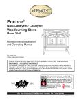
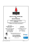
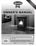
INSTALLATION, OPERATING and SERVICE MANUAL STATUS, CLASSIC, CLASSIC II MOBILE WOOD-STOVES MODELS NS220, NC100, NCM120 THE INSTALLATION OF THE UNIT SHALL BE IN ACCORDANCE WITH THE REGULATIONS OF THE AUTHORITIES HAVING JURISDICTION. HEAD OFFICE MARKETING / PRODUCTION Newmac Mfg. Inc. WAREHOUSE Newmac Mfg. Inc. LANCASTER CRESCENT P.O. BOX 9, DEBERT NOVA SCOTIA, BOM 1G0 PHONE: 902-662-3840 FAX: 902-662-2581 430 SPRINGBANK AVE., SOUTH WOODSTOCK, ONTARIO N4V 1B2 PHONE: 519-539-6147 FAX: 519-539-0048 EMAIL: [email protected] HOMEPAGE : newmacfurnaces.com NOTICE TO HOMEOWNER: READ AND SAVE THESE INSTRUCTIONS 2210254 NOVEMBER 2010 Subject to change without notice Printed: 156156 The Newmac NS220 (Status), NC100 (Classic) and NCM120 (Classic II, Mobile) are listed for USA and Canada under Solid-Fuel Space/Room Heater Standards UL1482, Underwriter’s Laboratories, and ULC S627, Underwriter’s Laboratories of Canada, by the Canadian Standards Association, a Nationally Recognized Testing Laboratory (NRTL/C). INSTALLATION REQUIREMENTS The installation must comply with the requirements of the regulatory authority in your area. In the United States, the installation must conform to the National Fire Protection Association Standard NFPA 211, Standard for Chimneys, Fireplaces, Vents, and Solid Fuel Burning Appliances and Codes. In Canada, the installation must conform to CAN/CSA-B365 Installation Code for Solid-Fuel-Burning appliances. Also in the United States, install in accordance with such codes as the BOCA National Mechanical Code, the Standard Mechanical Code, and the Uniform Mechanical Code. In the United States room heaters intended for installation in mobile homes are to be installed in accordance with the Manufactured Home Construction and Safety Standards published by the Department of Housing and Urban Development (HUD). Information that is provided on the appliance certification label takes precedence over that presented here. When this heater in not properly installed, a house fire may result. To reduce the risk of fire, follow the installation instructions. Contact your local building or fire officials about inspection requirements in your area. WARNINGS DO NOT CONNECT THIS UNIT TO A CHIMNEY FLUE SERVING ANOTHER APPLIANCE. DO NOT INSTALL MODELS NS220 (NEWMAC STATUS) OR NC100 (NEWMAC CLASSIC) IN A MOBILE HOME. DO NOT CONNECT HEATER TO ANY AIR DISTRIBUTION DUCT OR SYSTEM DO NOT BURN GARBAGE OR FLAMMABLE FLUIDS SUCH AS GASOLINE, NAPTHA OR ENGINE OIL. HOT WHILE IN OPERATION, KEEP CHILDREN, CLOTHING AND FURNITURE AWAY. CONTACT MAY CAUSE SKIN BURNS. WHEN INSTALLING THE NCM120 MAKE SURE THAT THE STRUCTURAL INTEGRITY OF THE MOBILE HOME FLOOR WALL AND CEILING/ROOF ARE MAINTAINED. SEE MOBILE HOME INSTALLATION DO NOT INSTALL NCM120 (NEWMAC CLASSIC II, MOBILE) IN A SLEEPING ROOM. Please read this entire manual before you install and use your new room heater. Failure to follow instructions may result in property damage, bodily injury, or even death. CHIMNEY This room heater requires at least a 6” diameter chimney flue and must be connected to either: 1. a chimney complying with the requirements for Type HT chimneys in the Standard for Chimneys, Factory-Built, Residential Type and Building Heating Appliance UL103 HT(USA) such as GSW type JSC, or CAN/ULC S629, 650C Factory Built Chimneys (Canada), such as GSW type JM or 2. a code-approved masonry chimney with an approved flue liner. INSTALLING HEATER Newmac recommends that the room heater be professionally installed. For NCM120 (Newmac Classic II Mobile) heater see additional installation requirements in “MOBILE HOME INSTALLATION”. 1. If a factory built chimney is required, install a suitable chimney listed for solid fuel according to chimney manufacturer’s requirements. 2. If a masonry chimney is to be used check with your local regulatory authority that it is suitable for solid fuel operation. 3. Ensure that all other openings into the chimney flue are sealed shut and that the heater will be the only appliance connected to the chimney flue. 4. Select location for heater close to chimney location and allowing for clearances to combustible materials. Install additional protection for combustible materials if clearances are reduced – see REDUCED CLEARANCES. 1 5. 6. 7. 8. 9. If the chimney connector must pass through a wall or partition of combustible construction, the installation must conform to the requirements of NFPA211 (USA) or CAN/CSA B365 (Canada). Note that the chimney connector must NOT pass through a ceiling or a roof space. Place heater on a listed non combustible and non-heat conducting stove-board or durable pad, equivalent to asbestos mill-board of at least 3/8” (10mm) thickness, according to the requirements of NFPA 211 (USA), CAN/CSA B365 (Canada) and the requirements of the regulatory authority. Using 6” (150mm) diameter mild steel (not galvanized) connector pipe and fittings suitable for solid fuel, connect the breech outlet of the room heater to the chimney. Secure each chimney connector joint with three sheet metal screws and connections to the appliance with a minimum of 2 sheet metal screws. For better performance, seal each connector pipe joint with a small amount of furnace cement. When laying out the connector pipe plan for a method of dismounting the assembly for inspection and cleaning of the connector pipes and the chimney flue. Ensure that the room heater and the connector pipe locations conform to the required clearance to combustibles. Ensure that a direct source of fresh outside air for combustion is available to the room heater. This is important as replacement air for the gases which the heater will be exhausting up the chimney. BEFORE FIRING HEATER Please note that some parts are shipped inside the appliance. Remove and assemble as required. If necessary, slide the firebricks back to the rear so that no gaps remain between them. CLEARANCES TO COMBUSTIBLES – FLOOR PROTECTION Refer to the certification label on the appliance and the following diagrams for the appropriate model being installed. WARNING: Install on durable non-combustible and non-heat conducting pad, equivalent to asbestos mill-board of at least 3/8” (10 mm) minimum thickness, which extends at least 8” (205 mm) from the unit on all sides, and 18” (455 mm) from the firedoor end. Alternatively install in accordance with provisions of NFPA 211 (USA) or CAN/CSA-B365 (Canada). Do not obstruct the space beneath the stove. WARNING: Maintain minimum specified clearances to combustible materials. Do not place fuel (wood) within specified clearances or within space required for charging and/or ash removal. CLEARANCE TO COMBUSTIBLES – WALLS AND CEILING NS220 (Newmac Status) 2 NC100 (Newmac Classic) NCM120 (Newmac Classic II, Mobile) USING SINGLE WALL CHIMNEY CONNECTOR NCM120 (Newmac Classic II, Mobile) USING CHIMNEY CONNECTOR TYPE APPROVED FOR CLEARANCE OF 9” OR LESS REDUCED CLEARANCES Approved double-wall chimney connector and/or approved non-combustible protection over combustible surfaces may permit the heater to be installed closer to combustible surfaces than the standard clearances to combustibles. Clearances may only be reduced by means approved by the regulatory authority. To reduce clearances to combustible materials, specified forms of wall protection must be installed. For acceptable methods and parts to be used, refer to NFPA 211 (USA) or CAN/CSA B365 (Canada). Since municipal bylaws vary it is recommended that you (the installer) check with your local authorities as to approved methods of wall protection for reduced clearances. 3 Ceiling Non-combustible wall protection 20 in min 500mm Non-combustible support spacers at least 8" (200mm) from center line Non-combustible support spacers Wall protection Wall Vertical steel channel standoff screw air space for free vertical air movement Heater Side view Non-combustible wall protection 3 in min 75mm 1 to 3 ins 25 to 75 mm air space for free vertical air movement Heater Reduced clearance Floor Combustible wall Typical non-combustible spacer detail Wall Top view 7/8in min 21mm 7/8in min 21mm TYPICAL SIDE-WALL PROTECTION FOR CLEARANCE REDUCTION OF 50% RULES FOR SAFE INSTALLATION AND OPERATION 1. 2. 3. 4. 5. 6. 7. 8. 9. Always connect this heater to a residential type chimney and vent to the outside. Never vent to another room or inside a building Read these rules and the instructions carefully. Check your local codes. The installation must comply with their requirements. Do not connect to aluminum Type "B" gas vent. An approved masonry or residential type pre-fabricated chimney for use with solid fuel is required. See CHIMNEYS above. The inside diameter must be at least 150 mm (6"). Make sure the chimney top is high enough to give a good draft. Keep the chimney and pipe clean inside to avoid blockage. Otherwise, smoking will result. Examine and clean flue pipe frequently to prevent chimney fires. To prevent injury, do not allow anyone who is unfamiliar with the operation to use the heater. Do not install damper or restrictions of any kind in flue pipe. Burn wood only. Do not use wet or green wood. The wetter or greener the wood, the more creosote will be produced. (See Facts on Creosote). Do not use artificial logs or barbecue charcoal fuel. CAUTION Indicates a situation in which injury or damage to your appliance, or both, could result if the caution is ignored. 1. Do not install models NS220 (Newmac Status) or NC100 (Newmac Classic) in a mobile home or trailer. 2. Do not install room heater in a sleeping room. 3. The NCM120 (Newmac Classic II Mobile) mobile home heater should be installed in the largest room of the mobile home. 4. Do not operate your heater unless it is maintained in a good airtight condition - otherwise overheating will result. 5. Do not operate your heater with the loading door open as excessive temperatures could result. 6. Do not connect to any air distribution duct or system. 7. Do not use chemicals or fluids to start the fire. 8. Do not burn garbage or flammable liquids, such as gasoline, naptha, engine oil, etc, as these may cause an explosion. 9. Never use gasoline, gasoline-type lantern fuel, kerosene, charcoal lighter fluid, or similar liquids to start or ‘freshen up’ a fire in this heater. Keep all such liquids well away from the heater while it is in use. 10. Hot while in operation. Keep children, clothing, and furniture away. Contact may cause skin burns, do not touch the heater until it has cooled. 11. Ensure that sufficient combustion air is available for the heater. Inadequate air can result in unsatisfactory operation and smoking. Be sure that sufficient air is provided to exhaust fans on other household devices. 12. Install a smoke detector to warn of possible hazardous situations. WARNING Indicates a situation in which serious injury or death could result if the warning is ignored. 1. When this room heater is not properly installed, a house fire may result. To reduce the risk of fire, follow the installation instructions. Contact local building or fire officials about restrictions and installation inspection requirements in your area. 4 2. 3. 4. 5. 6. Hazardous carbon dioxide or carbon monoxide gas may be produced by improper installation, operation, fuelling or maintenance of this appliance. As required by the installation codes, provide air for combustion from the outside into the room where the heater is located. For models NS220 (Newmac Status) and NC100 (Newmac Classic), if the intake is not in the same room, the air must have free access to the room. Install air duct for NCM120 (Newmac Classic II Mobile) as specified. Do not use substitute materials or unspecified components. Suitable original-equipment replacement-parts are available from Newmac Mfg. Do not use abrasive cleaners. Do not clean when hot. NOTE: The special paint used on your heater may give off some odor while it is curing during the first few fires. Build small fires at first. CHIMNEY CONNECTOR (STOVE OR FLUE PIPE) Newmac wood fired heaters require 6” (150mm) diameter mild steel chimney connectors of at least 24ga (0.53mm or 0.0206ins) metal thickness, or equivalent. (Galvanized steel is not acceptable). Secure each chimney connector joint with three sheet metal screws and connections to the appliance with a minimum of 2 sheet metal screws. For better performance, seal each connector joint with a small quantity of furnace cement. Ensure that the vent system can be taken apart for periodic inspection and cleaning. Chimney connector must not pass through an attic or roof space, closet, or similar concealed space or a floor or ceiling. Where passage through a wall or partition of combustible construction is desired, the installation must conform to NFPA 211 (USA) or CAN/CSA B365 (Canada) requirements. The crimped end of the chimney connector fits inside the heater flue collar. Additional pipe and elbow should be installed with CRIMPED END TOWARD THE HEATER. This will let condensation in the flue to run back into the heater. Chimney connectors for the NCM120 Newmac Classic II Mobile home heater must be sealed with furnace cement. REDUCING EXCESSIVE DRAFT Where permitted by the regulatory authority a hand operated flue pipe key-damper may be installed. CONNECTION TO A MASONRY CHIMNEY THROUGH A COMBUSTIBLE WALL The heater may be connected to a masonry chimney, which conforms to the installation code requirements. Various methods of connection are shown in these installation codes. Check with your local regulatory authority as to which methods they will accept. Care must be taken when the chimney connector passes through a combustible wall to ensure that there is sufficient clearance from the chimney connector to the combustible wall material. Fire clay liner Stud work Brickwork Minimum chimney clearance to brick and combustibles 2in (50mm) Minimum clearance 12in (305mm) of brick Minimum clearance 9in (230mm) Air space Sheet steel supports Solid-insulated listed factory-built chimney length Refractory cement Chimney connector Chimney connector Chimney length flush with inside of flue Use chimney mfr's parts to attach connector securely Refractory cement Chimney flue Minimum 12in (305mm) to combustibles Heater Chimney flue 18" Masonry chimney constructed to NFPA 211 Single wall vent connector Clearance to combustibles Using Fire clay liner 5 Using listed factory-built chimney length TYPICAL CONNECTION TO A MASONRY CHIMNEY THROUGH A COMBUSTIBLE WALL 6 CONNECTION THROUGH A MASONRY FIREPLACE A wood-fired space heater may be connected to a masonry fireplace if: 1. There is a connector that extends from the heater to the flue liner of the fireplace. 2. The cross-sectional area of the flue is no more than three times the cross-sectional area of the flue collar of the room heater. 3. There is a non-combustible seal below the point of entry of the connector. 4. The installation conforms to the requirements of your local codes (NFPA211 - USA), (B365 – Canada) Check with your local regulatory authority as to which methods they will accept. Flow area of flue is not more than 3x flow area of flue collar Listed liner section Non-combustible seal Connector extends from appliance to flue-liner Heater Cleaning and inspection cap Stoveboard or pad TYPICAL FIREPLACE CONNECTION CONNECTION TO A FACTORY BUILT CHIMNEY The room heater may be connected to a listed factory–built chimney which complies with the requirements of UL 103HT (USA) or CAN/ULC S629 (Canada). Check with your local regulatory authority for specific requirements. Follow the chimney manufacturer’s instructions when installing a factory-built chimney. Rain Cap Spark Arrestor Chimney section Storm collar Rain Cap Spark Arrestor Roof flashing Chimney section Attic insulation shield Firestop Chimney must be enclosed in living space Chimney section Storm collar Roof flashing Locking band Firestop Wall band Wall Thimble Decorator ceiling support Stove pipe adaptor Stove pipe adaptor Stainless Tee Chimney connector Single wall shown Chimney connector Single wall shown 18" Heater Heater TYPICAL FACTORY BUILT CHIMNEY INSTALLATION 7 Adjustable Support Clearance to combustibles FLUES AND CHIMNEYS – SOME BASIC PRINCIPLES 1. 2. 3. 4. 5. 6. 7. 8. 9. 10. 11. 12. 13. 14. 15. 16. 17. 18. 19. 20. 21. 22. 23. The chimney top should be higher than any other part of the house or any nearby surrounding objects – see installation code. A straight chimney is best. A chimney should be smooth on the inside. The flue pipe and chimney should be inspected periodically and cleaned if necessary. The smoke flue of a chimney must not be used for ventilation purposes. All openings apart from the one serving the heating appliance must be sealed closed. The chimney connection should be as short as possible with minimum number of elbows. Any horizontal pipe should be pitched upward toward the chimney at least ¼” per foot of horizontal pipe. Be sure that there is at least 18” (450mm) of clearance between horizontal single wall smoke pipe and the ceiling. Do not connect any other appliance to the same flue. Use three sheet metal screws to secure each joint. For better performance, seal each vent pipe joint with a small quantity of furnace cement. Ensure the vent system can be taken apart for periodic inspection. All openings into a chimney must be closed off airtight, except the one in which your smoke pipe enters. The chimney connector should not project into the flue and must fit tightly into the chimney hole. The chimney connector must fit the collar on the stove tightly and should never be reduced in diameter from that point. The chimney connector must not be made smaller where it enters the chimney hole. Enlarge the hole if necessary. The hardest work for a chimney is when the fire is first started, as the air in the flue is damp and the temperature lower than it will be when the fire is well under way. The draft in the chimney is more dependent upon the amount of hot air thrown into it than upon its size. A chimney may be much too large for ordinary house requirements, but there is little danger of its being too high where draft in concerned. The effective area of a chimney is the area at the smallest part. Therefore, see that it is not diminished by obstructions. Smoke and hot air will rise in a spiral column; therefore, a round flue is best, as cold air cannot fall in the corners. Long narrow flues are apt to cause trouble. Chimneys built on the outside of a house must be at least 8" thick to prevent chilling the flue space within. The chimney must be installed in accordance with these instructions and the chimney manufacturer’s instructions. OUTSIDE COMBUSTION AIR Provision for outside combustion air may be necessary to ensure that the heater does not discharge products of combustion into the house. If in doubt, it is advisable to provide additional air. For outside combustion air make-up, Newmac recommends that an opening, of 12 sq. inches (78 sq. cm.) free area be provided to the room in which the heater is installed. If the air is ducted from outside, a 4 inch round duct (to a maximum of 50 equivalent feet or 15m) should provide sufficient combustion air. If a duct is used, it should terminate at least 1 foot (0.3m) from the appliance and not be directly connected to it. Outside combustion air may be required if: a) the heater does not draw steadily, experiences smoke roll-out, burns poorly, or back-drafts whether or not there is combustion present; b) existing fuel-fired equipment in the house, such as fireplaces or other heating appliances, smell, do not operate properly, suffer smoke rollout when opened, or back-draft whether or not there is combustion present; c) any of the above symptoms are alleviated by opening a window slightly on a calm (windless) day; d) the house is equipped with a well-sealed vapor barrier and tight fitting windows and/or has any powered devices which exhaust house air; e) there is excessive condensation on windows in the winter; or f) a ventilation system is installed in the house. If these or other indications suggest that infiltration air is inadequate, additional combustion air should be provided from the outdoors Make sure that any code requirements are satisfied when installing combustion air make-up. 8 DUCTING OUTSIDE COMBUSTION AIR Indirect method – NS220 (Newmac Status) and NC100 (Newmac Classic): outside air may be ducted to a point no closer than 300 mm (12 in) from the heater, to avoid affecting the heater’s performance. Direct connection – NCM120 (Newmac Classic II, Mobile): This heater is approved for direct connection of outside air as described on page 12. POSSIBLE FLUE OR CHIMNEY DEFECTS From the foregoing basic principles for the regulation of chimney flues, it will be seen that unsatisfactory stove operation may be the result of any of the following possible chimney flue defects: 1. Insufficient height. 2. Surrounding nearby objects throwing air currents down the chimney. 3. Flues enlarged or contracted at some point. 4. Rubbish or soot obstruction in the flue. 5. Air leakage in cracks where mortar has fallen out. 6. Floor support or a pipe passing through or entering the flue. 7. Too abrupt offsets. 8. Other connecting flues 9. Chimney being used for ventilating basement 10. Chimneys too large for stove being used. 11. Flues being long and narrow 12. More than one smoke-pipe connected to the flue. 13. Chimney connector protruding too far into the chimney. FUEL Mixed dry hard wood will give the most heat. Your heater will handle most any type of wood, but some types produce more heat than others and will hold fire longer. Coal should never be used in a heater designed for burning wood. Never use driftwood that has been in salt water for a long period. The salt content may cause excessive corrosion and shorten the life of the firebox. Hard wood cut to 20” maximum length, and split 3” to 6” cross section is recommended for best operating efficiency. CAUTION: Burn untreated wood only. Wood containing preservative, metal foils, coal, plastic, garbage, sulfur or oil may be hazardous and damage the appliance. LOADING OF FUEL Do not overfill the firebox above the firebrick. Wood should be 3 to 4” below top of firebrick. A burned-out heat chamber may result. Do not use artificial logs. Build fire on the floor of the NS220 (Newmac Status) and on the built-in grates of the NC100 (Newmac Classic) and the NCM120 (Newmac Classic II, Mobile) heaters. Do not use additional grates or andirons to support the fire as these may create excessive heat. For the most heat, combustion air must be able to circulate around and through the fire. Do not block the air entrances inside the firebox with ashes. PREPARATION AND STORAGE OF FUEL Solid fuel should be cut and split prior to the heating season and stored in a well aired, dry place. Do not store fuel within the room heater clearances or within the space required for fuelling or ash removal. Fuel should be kept at least 5ft clear (1.5m) from the heater. The space around the heater should be kept free of litter and wood residue. LIGHTING and OPERATION 1. 2. 3. 4. 5. Set thermostat on HIGH to provide maximum draft. Open loading door and lay fire, using ample kindling to ensure rapid ignition. Prime chimney - hold lighted newspaper up towards flue baffle. Light fire and close loading door. Wait 3 - 5 minutes then add dry logs. (See section concerning Flue). 9 6. Set thermostat to maintain desired temperature in room. Medium setting is normally satisfactory. Set high or lower for maximum comfort. CAUTION: Do not operate this heater with the loading door (or ash door if fitted) open. This heater is designed for thermostatic operation. Continuous operation with a door open will over heat the unit. REFUELING CAUTION: Read the section on back-puffing before refueling heater. The loading door should be closed at all times except when refueling. If the door is allowed to remain open, the thermostat will not function, as it should. Before opening the loading door, make sure the thermostat is open. Allow the fire to burn rather briskly for a few minutes. Then open the loading door slowly. By allowing the fire to increase for a short period, a high draft condition has eliminated smoke in the firebox and the temperature has been raised which prevents a back or down draft. After refueling, set thermostat at the normal operating setting. DISPOSAL OF ASHES 1. 2. 3. 4. Ashes should be placed in a metal container with a tight fitting lid. The closed container of ashes should be placed on a non-combustible floor or on the ground, well away from all combustible materials pending final disposal. If the ashes are disposed of by burial in soil or otherwise locally dispersed, they should be retained in a closed container until all ashes have thoroughly cooled. Do not allow ashes to build up inside of firebox. This will reduce necessary air for proper combustion - keep ashes away from primary air intakes. NC100 (Newmac Classic) and NCM120 (Newmac Classic II, Mobile) – Keep the ash pit section free of excess ashes. Failure to do so will cause grate warpage and burn out. Cast iron parts must be “seasoned” to avoid cracking. Build only small fires during your early use. OPERATING HINTS A Heater puffs and fills room with smoke: 1. 2. 3. 4. B Check that sufficient outside combustion air is available to the heater. Check for air leaks in chimney connector. It is of utmost importance that installations are made airtight. This is best accomplished by using furnace cement at each pipe joint and where the elbow of first joint of pipe enters the chimney flue. Check for air leaks in chimney. Any air leaks existing between the top of the chimney vent and the heater may cause back-puffing. Here is the reason: NEWMAC wood-fired heaters are designed to operate on an airtight principle, when the combustion air damper has closed, which it does intermittently because it is controlled by the bimetal thermostat, the heater has to breathe throughout the hole in this damper plate. Therefore any air leaks existing, as mentioned above will cause the draft to draw at points where least resistance is offered, such as at pipe joints, where pipe enters chimney flue, around loose flue thimble, other flue openings into chimney around clean-out doors permitting air to seep into chimney. When this takes place, the gases and smoke are not drawn off the heater in proper quantity, causing them to build up in volume within the heater, which results in back-puffing. All such leaks must be sealed off airtight! In other words, the entire chimney pull or draft must be on the damper entrance only. Check for chimney connector or chimney clogged with bird nests, loose brick, creosote, etc. Heater burns too much fuel: 1. 2. Check air leaks around loading door. NOTE: Never operate with loading door open. Check for air leaks around flue collar and firebox. 10 BACK-DRAFT There are two main causes of chimney downdraft. One readily recognized is air currents being deflected down the chimney by nearby higher objects, such as a tree, building or a hill. The other cause, equally or more common, but seldom understood or recognized, is that in many chimneys the flue gases are chilled too quickly as they pass up the chimney. The temperature of the flue gases drop, they become heavy, and then other gases from the wood fire have to push a heavy column of air ahead of them in order to escape up the chimney. This often results in back-puffing or backpressure, odors in the house, or poor combustion, which can be annoying. Remember, the hotter the air in the flue, the stronger the draft. Any air entering the chimney, which has not passed through a hot fire will cool the air in the flue and spoil the draft and aid in the formation of creosote. BACK-PUFF Back-puff is the sudden ignition of gases within the heater, which happens when air is suddenly admitted. This is because the combustion rate in an airtight heater is air Iimited. Air for combustion is regulated by the primary air manifold and the thermostat. If air is suddenly admitted to the firebox by opening the loading door, air will rush in and the gases will ignite. The combustion surge of the gases is so quick that the resulting pressure can force the hot gases out any available opening such as the loading door. Therefore, be cautious! Open any door or opening on an airtight heater very slowly and only then after being certain the thermostat door on the heater is open. The possibility of back-puffing is one reason that children or anyone who is unfamiliar with the heater should be cautioned about touching the heater. ASSEMBLY INSTRUCTIONS - NS220 (Newmac Status) 1. 2. 3. 4. 5. 6. 7. 8. 9. 10. Remove shipping carton. Remove top of unit with louver. Place firebox of heater on floor. Open loading door - packed inside of heater firebox are legs, bolts, nuts, floor protectors, knob. Turn over base legs down, Place heater firebox on base plate and line up with 2 holes at front, Secure heater firebox at front with 2 bolts and lock nuts. Attach 2 clamps at back of unit to bottom base plate Place louvered top onto heater firebox. Install knob on lift top. NOTES: Make sure all attached components are securely tightened to the base legs - firebox to base and clamps at back. Check operation of loading door to be sure it locks tightly when closed and forms good seal with firebox. BASE ASSEMBLY - NS220 (Newmac Status) 11 DAMPER ADJUSTMENT – NS 220 (Newmac Status) ONLY The adjustment plate in the damper on the NS 220 Status may be set to change the idle rate. Open to increase and close to decrease idle rate. Leave adjustment for a few days after changing to see if idle rate is better for your situation. See diagram on page 16. THE SECONDARY AIR INTAKE – NC100 (Newmac Classic) ONLY The secondary air inlet allows the proper amount of combustion air to enter the firebox ABOVE the primary burning fuel. In various stages of operation, an airtight heater may not receive enough combustion air to properly burn all the gases that accumulate about the main combustion. It, therefore, is necessary in some manner to admit air to the area in such a way as to burn these gases but not to burn any primary fuel. The secondary air intake reduces creosote accumulation by keeping a steady flame burning in the stove above the primary fuel. It is recommended upon installation of the stove that the adjusting plate, which is visible through the opening in the back of the stove toward the flue collar, be adjusted to a point where the secondary air is almost closed. Once this is set for a certain locality, there should be no problems what-so-ever in the fire holding overnight and functioning properly. Check the secondary air inlet. It is located in the back of the heater, near the flue collar. If a creosote condition occurs, set the opening to ½”. MOBILE HOME INSTALLATION FOR NCM120 (Newmac Classic II, Mobile) CHIMNEY AND COMBUSTION AIR DUCT PREPARATIONS NCM120 (Newmac Classic II, Mobile) requires out door air and must be anchored to the floor. Do not install the heater in a sleeping room, it should be located in the largest room of the mobile home. Only models certified for mobile homes may be installed in mobile homes The structural integrity of the mobile home’s floor, wall, and ceiling/roof must be maintained. Locate the heater so that the hole for the roof support and hole in the floor for the air inlet clear between joists. The NCM120 Newmac Classic II, Mobile) room heater must be connected to a chimney complying with the requirements for Type HT chimneys in the Standard for Chimneys, Factory-Built, Residential Type and Building Heating Appliance UL103 (USA), or CAN/ULC S629, 650C Factory Built Chimneys (Canada). In USA use GSW Max! Super Chimney model JSC 2100 UL components and in Canada use GSW Super Chimney Max! model JM 2100 ULC components. The use of the specified components is important. Do not use other than the specified components. 1. 2. 3. Place heater onto location allowing for proper minimum clearances to combustibles as shown. Mark center point where the chimney goes through the ceiling and roof. On same center outline square X = 12” x 12” (305mm x 305mm) – USA, or 14” x 14” (355mm x 355mm) – Canada framing opening as required by approved chimney support. Check to make sure no roof joist is in the way. Should there be one, move Heater to the left or right so that it lines up with the newly located center point/frame opening. Maintain vapor barrier. TYPICAL FRAMING DIMENSIONS 4. Mark outline to the outside air duct on floor again, making sure no joist has to be cut. Frame opening and maintain vapor barrier. Duct framing dimensions are 3-1/2” x 6” (89 x 152mm). 12 450 200 200 810 485 NCM120 Air duct location cut out 150 90 Stove Board 50 3.5 7 34 ins mm 195 LOCATION AND DIMENSIONS OF AIR INTAKE DUCT HOLE AND FLOOR PROTECTOR AS SEEN FROM TOP 5. 6. Remove the heater, cut the holes and prepare framing. Restore the integrity of the vapor barrier with suitable tape and/or caulking. Install chimney ceiling support box JSC6CCSB (USA) or JM6CCS (Canada). Slide into opening level and nail through box framing using four 2” spiral nails or equivalent per side. Rain Cap Spark Arrestor Chimney section Storm collar Roof flashing Overlap roof shingle Ceiling Support Box TYPICAL CEILING SUPPORT BOX INSTALLATION 7. 8. Prepare floor protector. Locate onto floor and cut 3-1/2” x 6” (89 x 152mm) hole. Position floor protector and install outside air duct through floor. Mobile Home Heater Stove Board Optional seal/caulk with non-combustible silicone sealant Floor Bracket Vapour Barrier Floor Joist Insulation Outside Air Duct Screened End INSTALLATION OF OUTSIDE AIR DUCT AS SEEN FROM SIDE 9. Place heater in position. Be sure to lift heater in front and carefully slide over air duct. 10. Attach floor anchors. Drill 1/8: diameter holes and fasten to rear of heater base and floor with sheet metal screws (#10 x ¾”). 13 Rear of heater Sheet metal screws Mobile Home Heater Wood screws Stoveboard Floor Steel bracket FLOOR ANCHOR INSTALLATION AS SEEN FROM SIDE 11. Use chimney connector or stovepipe adapter JM586ASE for connecting approved pipe between chimney and cast flue collar on top of heater. 12. Install chimney length as required. NOTE: The chimney must be at least 3 feet above the highest point where it passes through the roof of the building and not less than 2 feet above the highest roof surface or structure within 10 feet horizontally. Not more than 8” of chimney cap above the top of the flue may be considered in computing this height. 0 to 10 ft Min 2 ft Min 3 ft Min 10 ft Min 2 ft Min 3 ft BASIC RULE FOR CHIMNEY TERMINATION HEIGHTS ABOVE ROOF 13. Install roof flashing (JSC6 ATC, AFA, AF2, or AF3 - USA), (JM6 ATC, F1, or F2 – Canada), storm collar and rain cap. a. Ensure that you have the proper roof flashing; check your roof pitch using a level and two rulers. Level 12" rule Pitch 3/12 Roof ROOF PITCH See the manufacturer’s catalog and instructions for flashing and pitch recommendations. b. Slide a Roof Flashing suitable to your roof slope over the chimney. Place the top edge of flashing plate under the shingles. Tighten the roof-flashing band around the chimney. NOTE: At the top edge of the flashing plate, lift the shingles and nail the plate to the roof deck. Then cement shingles to plate with suitable waterproof mastic. Chimney opening Chimney roof flashing Shingles over flashing Direction of slope water runoff Roof cement as required Flashing over shingles Roof shingles ROOF FLASHING 14 c. Ensure the chimney is plumb. Square up the flashing plate and nail in place to the roof deck. Use 12 nails and neoprene washers or cover the heads with a suitable waterproof mastic, Rain Cap Spark Arrestor Chimney section Storm collar Roof flashing Overlap roof shingle Ceiling Support Box TYPICAL CHIMNEY INSTALLATION d. Wrap the Storm Collar around the chimney above the flashing. Secure the ends together loosely with the nuts and bolts supplied. Slide the collar down the chimney until it contacts the flashing guides and/or draw band. Tighten the nuts and bolts and seal the Storm Collar to the chimney with suitable waterproof non-combustible mastic. After installation check to ensure that the flashing guides maintain an air space between the Storm Collar and the cone flashing. WARNING: Do not block the air space between the storm collar and the cone flashing. e. The flashing and storm collar should be painted to match the roof shingles. This will extend its life and improve the appearance. Clean and paint with suitable painting products. f. Continue adding chimney lengths until the proper height is achieved. Install a rain cap (standard or deluxe model) and lock it in place by turning clockwise until tight. g. If the chimney extends more than 5’ (1600mm) above the roof deck, roof guys are required. GSW Model J6RG roof guy kit is used this application. The draw band must be clamped around the chimney and the two legs bolted to the roof. Seal the roof with a suitable waterproof mastic. Tighten the two leg clamps to fix the position of the telescopic legs. CHIMNEY REMOVAL FOR MOBILE HOME TRANSPORTATION Before transportation of the mobile home, the chimney connector should be disconnected and the chimney removed according to the chimney manufacturer’s instructions. It should be replaced, secured and re-sealed before the heater is used. USING HEATER FOR EMERGENCY COOKING – NS220 (Newmac Status) and NC100 (Newmac Classic) ONLY This heater is designed so that the cabinet top can be lifted and cooking vessels set on top of the firebox for emergency cooking or water heating. NOTE: This lift top feature is intended for emergency cooking only, such as when regular cooking facilities are temporarily out of service. When it is being used as a heater, the cabinet top must be in place. The automatic thermostat will only work properly when the cabinet top is in place and the cabinet door is closed. When the top is open it is necessary to operate the thermostat manually. 15 CREOSOTE AND THE NEED FOR REMOVAL When wood is burned slowly, it produces tar and other organic vapors, which combine with expelled moisture to form creosote. The creosote vapors condense in the relatively cool chimney flue of a slow-burning fire. As a result, creosote residue accumulates on the flue lining. When ignited this creosote makes an extremely hot fire. The chimney connector and chimney should be inspected at least once every two months during the heating season to determine if a creosote build-up has occurred. If creosote a significant layer of creosote (1/8 inch, 3mm or more) has accumulated it should be removed to reduce the risk of a chimney fire. CAUTION: Increase the minimum fire only as much as necessary to reduce the formation of tars. Increasing the minimum fire may cause overheating on warm days. Establish a routine for the fuel, wood burner and firing technique. Check daily for creosote build-up until experience shows you how often you need to clean to be safe. Be aware that the hotter the fire the less creosote is deposited, and weekly cleaning may be necessary in mild weather even though monthly cleanings may be enough in the coldest months. Contact your local municipal or provincial fire authority for information on how to handle a chimney fire. Have a clearly understood plan to handle a chimney fire. Creosote is caused from the condensation of the vapor that exists within the escaping smoke – drier wood is less likely to form creosote. The density of the vapor is dependent upon the moisture content of the gases in the flue. The hotter the escaping gases in the chimney, the less creosote formation you will have. A well-constructed chimney with smooth liners and a flue that is well insulated from the colder air is best. Chimneys built with porous brick, or ones with loose brick, or ones constructed with stovepipe are undesirable because the colder air condenses the escaping gases much more rapidly than they are in a well-constructed chimney. The formation of creosote could also be caused by a severe downdraft condition caused from taller objects surrounding the chimney such as a hill, trees, other buildings, or chimneys of poor construction. Under such conditions, the cold air drifts into and down the chimney, chilling the escaping vapor within the smoke below the dew point and depositing this residue on the inside of the chimney walls. It is important that you inspect the chimney connector and chimney flues more frequently than every 1 to 2 months until you see what pattern of deposition is occurring. WARNING: If wood with a high pitch content is used or the chimney is not properly constructed or insulated or if the chimney connector is excessively long or has several elbows or turns, more frequent inspections must be made. If creosote is a problem, the following may reduce it: 1. Dry wood. 2. More frequent refueling. 3. Avoid prolonged operation of the heater with the thermostat at its lowest setting. 4. Use logs as large as possible. A CAUTION NOTE ABOUT CHIMNEY FIRES If you suspect a chimney connector or flue fire, you should reduce all combustion air to a minimum. Turn the heater thermostat knob to LOW. Make sure that the loading door (and the ash door on the NC100 and NCM120 Classic heaters) is completely closed and secure. If necessary call you local fire department. Do not take down the flue pipes until the fire has been completely extinguished. When wood is burned slowly such as under low fire conditions, tars are formed in the flue products. These tars, in time, are deposited on the inside of the flue and chimney pipe. With enough build-up these tars can ignite and cause a fire inside the chimney until the burnout is complete. A listed chimney is sufficient to contain the fire, but distortion can result. If such a burnout should occur, your chimney should be inspected immediately and any deformed, warped or otherwise distorted parts replaced before further use. 16 RECOMMENDED BI-METAL AND DAMPER SETTING The thermostat control (bi-metal) was adjusted at the factory at room temperature. Do not tamper with the control or the damper lift mechanism as this may cause the room heater to overheat. Thermostatic Bi-metal control Thermostatic Bi-metal control Chain Chain Draft Adjuster Firebox Combustion Air damper Door NC100, NCM120, Classic and Classic II Combustion Air damper NS220 (Newmac Status) CARING FOR ENAMELED PARTS NC100 (Newmac Classic) and NCM120 (Newmac Classic II, Mobile) This heater has enameled outside jacket. Enamel baked onto the steel or iron is very serviceable, but it will not stand rough handling or abuse. When setting up your heater use care in handling. Clean with soap and warm water when heater is not hot. DO NOT use any acids or scouring soap, as these wear and dull the finish. LOADING DOOR ADJUSTMENT Should it be necessary to adjust or tighten the loading door ( NS220 - Key 20: NC100 - Key 32: NCM120 - Key 36) remove bolts in door latch bracket (NS220 – Key 28: NC100 - Key 39: NCM120 - Key 43) place washers inside (between bracket and front) this will adjust latch bracket closer to front and tighten door seal. REPLACEMENT OF FIREBOX LINERS – NS220 (Newmac Status) All firebox liners with the exception of the front liners and economizer (Key 11, 23 and 24) are secured without the use of screw or bolts. To achieve this they have to be placed any or all liners this sequence must be followed otherwise they cannot be removed. Removal Procedure: 1. 2. 3. 4. 5. 6. 7. 8. 9. Remove flue baffle (Key 14) by lifting it up and sliding it forward through the door opening. Lift up and slide top back heat liner (Key 15) forward and through door opening. Slide upper side liner - left or right – (Key 27) toward back of firebox and remove through door opening Remove refractory bricks on each side (5 per side). Take out bottom back heat liner (Key 16). Lift up and remove lower right side brick liner (Key 26). Remove bottom bricks Lift up and remove lower left side brick liner Slide angled side bricks (2 per side) from side brick liner. NOTE: To remove economizer and/or front liners unscrew fastening bolts and lift out. To replace the firebox liners follow the removal procedure in reverse, i.e. start with Step 9 to slide side bricks into liner etc. 17 CIRCULATING FAN MODEL NBK-100 Optional for NC100 (Newmac Classic) and NCM120 (Newmac Classic II, Mobile) ONLY NO OTHER CIRCULATING FAN IS CERTIFIED FOR THESE HEATERS INSTALLATION: To install on heater, place outlet of fan box assembly into air duct located at bottom of rear panel. Then attach fan assembly to rear panel with sheet metal screws provided. (Use #30 Drill). Make sure that the power supply cord to the fan box is protected from possible damage. OPERATION: Use 115V 60Hz 1PH AC current only. 1. After the heater is in operation, and the toggle switch is in the automatic position, the circulating fan will operate. It is controlled by a built-in heat sensing fan switch. 2. The heater back panel must get hot to operate the fan switch, which controls the blower motor. The disc thermostat fan switch must touch the rear panel when set in the automatic position. 3. Normally it takes 30-45 minutes for the fan on the heater to operate after starting. 4. The circulating fan may also be set for continuous operation by setting the switch in the “ON” position. Oil the blower motor twice a year with (2) drops of S.A.E. 30 oil Secure with sheet metal screws Heater rear Optional blower NBK-100 Classic Models NC100 and NCM120 Key No. Part No. DESCRIPTION 1 2 3 4 5 6 7 8 2220035* 2220035* 2220035* 2040033 2220035* 2220035* 2220035* 2040034 Fan Housing Assembly Inside Bracket Fan Motor Disc thermostat Snap Bushing Strain Relief Cord with Plug Toggle Switch * Part Number 2220035 is a sub-assembly including all the parts indicated 17 FLOOR BRACKET INSTALLATION - NCM120 – NEWMAC CLASSIC II MOBILE 1. 2. 3. 4. After heater is in position, set brackets in position as shown. Drill 1/8” diameter holes in heater casing and floor for screws. Insert floor wood screws, provided, (#10x1-1/2”) through bracket into floor. Insert sheet metal screws, provided, (#10 x ¾” sheet metal) through bracket into casing, and secure. Part Number 4110562 4100148 Part Floor bracket Screws bag Number required 2 1 TO ORDER REPAIR PARTS This manual will help you to obtain efficient, dependable service from the heater, and enable you to order repair parts correctly. Keep in a safe place for future reference. The use of the specified components is important. Do not use other+ than the specified components. When ordering, always give the full model number which is on the identification plate attached to the back of the heater, and always give the following information: 1. The Part Number (not key number) 2. The Part Description 3. The Model Number of the appliance 4. Number of Parts Required WARRANTY PROCESSING The following is required to process warranty claims: 1. 2. 3. 4. 5. Owner’s name and address Installer’s name, address, and phone number Serial Number Model Number Installation Date Newmac must issue a “Returned Goods Number” prior to acceptance of returned goods. Refer to your “Newmac Wood-stove Limited Warranty” for terms and conditions. 18 REPLACEMENT PARTS List Part Numbers – Newmac Status Model NS220 Wood Heater KEY NO. 1 PART NO. 2140050 2 2210255 High/Low Label 3 2160006 Cotter Pin 1/16 x ¾” 4 2220006 7/8” x 3/8” Diameter Spring 5 3090359 Thermostat Stop 6 3090358 Thermostat Standoff 7 2220007 BI Metal Thermostat Spring 8 3070015 Damper Chain 9 4110534 Draft Door Painted 10 4110560 Cast Air Inlet 11 3090354 Smoke Pipe Baffle 12 4110535 Cast Pipe Connector Painted 13 4110537 Louvre Panel Painted 14 3090360 Scandinavian Baffle 15 4060291 Top Rear Brick Loc Assly 16 4060290 Rear Brick Rack Assly 17 4110538 Main Body Assly Painted 18 2030011 Split Brick 19 4110532 Draft Box Painted 20 4160125 Firedoor C/W Rope Gasket Glued 21 4110539 Door Handle 22 2160011 23 3030010 Door Pins (7/32 x 3.25”) Front Liner 24 3030010 Front Liner 25 28 4110536 3120163 3120160 4060293 4060292 4110531 Base Panel Assly Painted Brick Spacer Bottom Brick Rack Right Top Brick Rack Left Top Brick Rack Door Catch Painted 29 3040234 Base Retainers (In Parts Bag 4100150) 30 2080080 Door Gasket 42” Rope 31 4100150 Parts Bag 32 2210254 Instruction Manual 33 4110530 Draft Screen Painted 34 4110561 Wooden Handles, Stained Brown (In Parts Bag 4100150) 35 4110561 Wooden Handles, Stained brown (In Parts Bag 4100150) 36 4060285 Inner Draft Chute Assly 26 27 DESCRIPTION Draft Control Knob **NOTE: Some parts available as complete assemblies only 19 REPLACEMENT PARTS – NEWMAC STATUS NS220 . 20 REPLACEMENT PARTS List Part Numbers – Newmac Classic Model NC100 Wood Heater KEY NO. 1 2 3 4 5 6 7 8 9 10 11 12 13 14 15 16 17 18 19 20 21 22 23 24 25 26 27 28 29 30 31 32 33 34 35 36 37 38 39 40 41 42 PART NO. 2140050 2210255 2160006 2220006 3090359 3090358 3090359 2220007 4110535 2220013 4110541 2160011 4110561 4110542 4110545 4110561 2220016 3120168 2030011 4110544 4110547 2210257 4110543 4110551 3070017 4110560 2170022 4060314 4060315 3030014 2160011 4160126 2080080 4160127 2080080 4010315 4110539 4110561 4110531 N/A 4110546 4110549 DESCRIPTION Draft Control Knob High/Low Label Cotter Pin 1/16 x ¾” 7/8” x 3/8” Diameter Spring Thermostat Stop Thermostat Standoff Thermostat Stop Bi Metal Thermostat Spring Cast Pipe Connector Painted Hinges 1 ½” x 1 ½” Top Louvre Panel (Painted) 7/32 x 3 ¼” Steel Door Pins Wooden Knobs Stained Brown Rear Panel Assembly (Painted) Casing Door (Painted) Wooden Knobs Stained Brown Roller Catch Rear Brick Spacer Split Brick Casing End (Painted) Screen Assembly (Painted) Classic Label Front Bottom Louvre Panel (Painted) Draft Door Top Damper Chain Cast Air Inlet Cast Iron Grates Top Brick Rack Bottom Brick Rack Front Liners 7/32 x 3 ¼ “ Steel Door Pins Firedoor c/w Rope Gasket Glued Door Gasket 42” Rope Ashdoor c/w Rope Gasket Glued Ashdoor Gasket 28.8” Rope Ashpan Door Handle Wooden Handles, Stained Brown Door Catch Painted (Only 1 Replaceable) N/A Casing Door Frame End (Painted) Firebox Assembly (Painted) NOTE: Some parts available as complete assemblies only. 21 REPLACEMENT PARTS - NEWMAC CLASSIC NC100 22 REPLACEMENT PARTS List Part Numbers – Newmac Classic II Mobile Model NCM120 Wood Heater KEY NO. 1 2 3 5 6 7 8 9 10 11 12 14 15 16 17 18 19 20 21 22 23 24 25 26 27 28 29 30 31 32 33 34 35 36 37 38 39 40 41 42 43 44 45 46 47 PART NO. 2140050 2210255 2160006 2220006 3090359 3090358 3090359 2220007 4110535 2220013 4110558 4060317 3080177 4110557 4110545 4110561 2220016 3120168 2030011 4110544 4110547 2210258 4110556 4110551 3070017 4110560 2170022 4060314 4060315 3030014 2160011 4160126 2080080 4160127 2080080 4010315 4110539 4110561 4110531 4110546 4110555 See # 16 3160385 4010325 DESCRIPTION Draft Control Knob High/Low Label Cotter Pin 1/16 x ¾” 7/8” x 3/8” Diameter Spring Thermostat Stop Thermostat Standoff Thermostat Stop Bi Metal Thermostat Spring Cast Pipe Connector Painted Hinges 1 ½” x 1 ½” Top Louvre Panel (Painted) Baffle Supports Baffle Rear Panel (Painted) Casing Door (Painted) Wooden Knobs, Stained brown Roller Catch Rear Brick Spacer Split Brick Casing End (Painted) Screen Assembly (Painted) Classic II Mobile Label Front Bottom Louvre Panel (Painted) Draft Door Top Damper Chain Cast Air Inlet Cast Iron Grates Top Brick Rack Bottom Brick Rack Front Liners 7/32 x 3 ¼ “ Steel Door Pins Firedoor C/W Rope Gasket Glued Door Gasket 42” Rope Ashdoor C/W Rope Gasket Glued Door Gasket 28.8” Rope Ashpan Door Handle Wooden Handles, Stained Brown Door Catch Painted (Only 1 Replaceable) Casing Door End Frame (Painted) Firebox Assembly (Painted) Spot Welded to Rear Panel Ash Pan Support Combustion Air Tube Assembly (Required for Mobile Home) Floor Anchor Brackets (Application – Order Separately) NOTE: Some parts available as complete assemblies only. 23 REPLACEMENT PARTS – NEWMAC CLASSIC MOBILE NCM120 24 NEWMAC STATUS, CLASSIC AND CLASSIC II MOBILE WOOD-STOVES LIMITED WARRANTY Model: Serial No: Date of Installation: 1. WARRANTY. Effective September, 2004, vendor warrants, upon and subject to the following terms and conditions, that, if items of the GOODS, identified above, manufactured by it and sold as new are found to be defective in workmanship or material prior to the end of the period (the "Vendor's Warranty Period"), which is five (5) years from date of installation, Vendor shall, within a reasonable time, at Vendor's option, either repair the Goods, provide a replacement part or parts (which may be reconditioned) for the Goods, refund the purchase price of the Goods without interest upon return of the Goods, exchange other goods for the Goods or grant a reasonable allowance on account of any defect. Any installation, labour, construction, transportation or other related costs or expenses arising from defective parts or repair or replacement will not be covered by this warranty, nor will Vendor assume responsibility therefor. Notwithstanding the foregoing, the following are special exclusions from the foregoing warranty: (a) decorative trim pieces, fans, electrical parts, internal parts and refractory have a warranty of 90 days. Vendor makes no warranty with respect to damage caused by any of the following: (a) improper operation and/or improper installation; (b) failure to remove plastic protective covering; (c) use of acidic or abrasive cleaners; (d) mortar or any other building material; (e) scratching or denting during installation; (f) exposure or storage in a non-controlled environment; (g) tampering, (h) down drafts or spillage caused by environmental conditions such as nearby trees, buildings, roof tops, hills or mountain, or (I) inadequate ventilation or negative air pressure caused by mechanical systems such as furnaces, fans and clothes dryers. Vendor makes no warranty with respect to Goods sold by it as used goods or with respect to components of the Goods or accessories of the Goods which are not manufactured by Vendor but, in the event that such components are the subject of a warranty by the manufacturer thereof in favour of Vendor, Vendor hereby assigns to Purchaser to the fullest extent possible the benefit of any such warranty. Vendor's obligations under this warranty are conditional on Purchaser demonstrating that the Goods have been stored, assembled, installed, maintained and operated only in accordance with the instructions issued by Vendor and with standard industry practice, and on Purchaser notifying Vendor in writing of any alleged defect with fourteen days after the alleged defect shall have become reasonably apparent to the Purchaser and affording Vendor a reasonable opportunity to investigate the alleged defect. No goods shall be returned to Vendor until after approval by Vendor and receipt by Purchaser or written shipping instructions from Vendor. Any repair done or any replacement part provided under this warranty is warranted by Vendor only to the expiration of the Vendor's Warranty Period. Vendor shall not be responsible under this Warranty for any shipping, insurance, removal or installation cost nor, unless the goods warranted are defective in workmanship, for any labour costs. Vendor shall charge its usual fees (plus expenses) for any work (including inspections and repairs) which is not covered by this Warranty. This warranty is non-transferable, and is made to the original retail purchaser, provided that the purchase was made through an authorized dealer of the Vendor. If warranty service is needed contact your dealer. Make sure you have your warranty, your sales receipt, the model/serial number and inspector number of your Goods. 2. Exclusivity of purchaser's remedies. Except as expressly stated herein, purchaser shall have no remedies, whether in contract, tort or otherwise, with respect to or in any way arising out of the sale condition or operation of the goods. 3. Exclusion of warranties and exclusion of liability. Except as expressly stated herein, all warranties, conditions, representations and collateral agreements, express or implied, statutory or otherwise, including without limitation any implied warranty or condition of merchantability, quality or fitness for purpose are hereby excluded, and vendor shall not be liable, whether in contract, tort or otherwise for any loss injury expense or damage of any kind whatsoever (including, without limitation, special consequential, incidental or indirect damages including loss of use, earnings or profits) in any manner resulting, whether or not from negligence, gross negligence or fundamental breach by vendor, its employees, agents or servants. 25