1
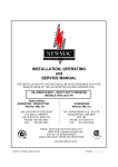
INSTALLATION, OPERATING and SERVICE MANUAL NEWMAC ADD-ON WOOD FURNACE MODEL WAO E All installations must be made in accordance with local and provincial or state codes which may differ from the manual. HEAD OFFICE MARKETING / PRODUCTION Newmac Mfg. Inc. WAREHOUSE Newmac Mfg. Inc. DEBERT AIR INDUSTRIAL PARK, 208 LANCASTER CRESCENT P.O. BOX 9, DEBERT NOVA SCOTIA, BOM 1G0 PHONE: 902-662-3840 FAX: 902-662-2581 430 SPRINGBANK AVE., SOUTH WOODSTOCK, ONTARIO N4V 1B2 PHONE: 519-539-6147 FAX: 519-539-0048 EMAIL : [email protected] WEB SITE : newmacfurnaces.com NOTICE TO HOMEOWNER: READ THESE INSTRUCTIONS SAVE THESE INSTRUCTIONS CSA B415.1 156156 2210367 June 2012 Subject to change without notice Printed: ADD-ON SOILD FUEL FURNACE MODEL WAO E GENERAL INSTRUCTIONS It is the responsibility of the consignee to the furnace to examine the packages for damage and, if found, to note the same on the Carrier’s Bill of Lading. Model WAO E has the furnace in one package and the firebrick in another package. The optional blower section is shipped separately. PACKAGE CONTENTS: 1. Heat exchanger with all panels installed, thermostat, draft fan, instruction booklet, relay, relay transformer, brick rack, draft regulator, 8 split bricks and baffle plate in firebox. 2. 20 full firebrick in 2 cartons of 10 each. 3. Optional Blower Section 4. Blower Accessory Package PERFORMANCE WITH WOOD FUEL Category # Burn Rate g/h g/mj High Med-High 6.63 3.12 3.86 1.99 0.043 0.040 Direct Output BTU 89,465 49,146 Med-Low Low 2.49 1.78 0.95 0.95 0.020 0.030 38,642 30,995 Direct Efficiency CSA Efficiency 72.5 83.5 73.7 76.7 82.1 92.5 78.9 77.2 MINIMUM INSTALLATION CLEARANCE FROM COMBUSTIBLE MATERIALS Fire door end 48” Flue Pipe One Side 6” Supply plenum and takeoff ducts to 6’ from furnace Other side (walkway) 24” Duct beyond 6’ from furnace Access Door end 30” Floor Solid fuel or other combustibles must not be stored within the above clearances. 18” 6” ½” Non-combustible INSTALLATION This unit shall be installed in accordance with the instructions of the manufacturer and in a manner acceptable to the regulatory authority by mechanic experienced in such service. When required by the regulatory Authority, such mechanics shall be licensed to perform this service. Check with provincial, state or local codes concerning clearances, chimney requirements and other installation procedures not set forth in this manual. This furnace must be connected to a solid-fuel rated chimney. Before this unit is installed to the oil furnace chimney in conjunction with the oil furnace, the chimney will have to be checked to ensure that it complies with the applicable standards. In Canada, factory built chimneys must comply with ULC S629 and masonry chimneys must comply with CSA-A-405. In the US, factory built chimneys must comply with UL 103, C S629 and masonry chimneys must comply with CSA-A-405. In the US, factory built chimneys must be constructed to UL 103, “Standard for Factory-Built Chimneys for Residential Type and Building Heating Appliances.” The installation must conform with the regulations of the local authorities having jurisdiction and with the applicable Electrical Code. In Canada, the regulations in C.S.A Standard B365 “The Installation Code for SolidFuel Burning Appliances and Equipment” apply. Similarly, In the United States, the regulations in NFPA 211, Standard for Chimneys, Fireplaces, Vents, and Solid Fuel-Burning Appliances“ and NFPA 90B, “Standard for 1 the Installation of Warm Air Heating and Air-Conditioning Systems” apply. If changes are made to the installation of the oil furnace, for Canada this shall comply with C.S.A Standard 139, “Installation Code of Oil Burning Equipment”. If changes are made to the installation of the oil furnace, for the U.S. this shall comply with NFPA 31, “Standard for the Installation of Oil-Burning Equipment.” This furnace is certified for series connection to the outlet only of an existing Oil fired furnace. This furnace may be added to an oil furnace having an oil input as shown on the original name plate between .75 GPH minimum and 1.10 GPH maximum for “Inline” duct connection as shown in FIG. 8. Do not use duct elbows having an inside radius of less then 150 mm (6 in). Install brick in firebox according to FIG. 6. After brick is in position place 2” of sand in bottom of firebox. (Use pit sand only.) Connect wiring according to appropriate Wiring Diagram – FIG. 10, 11, 12 or 13. Do not use a manual flue damper with this furnace. Optimal draft should be controlled by means of the supplied barometric draft regulator – adjust to a -.03 to -.05 draft at the chimney. This must be done by means of a draft meter. The maximum draft is not to be more than -.05 as damage can result to the furnace when used as a gravity unit. The test must be made between the flue collar on the furnace and the draft regulator. Newmac requires a minimum 7” round or equivalent rectangular or square flue (inside dimension). The minimum flue connector size is also 7” diameter. The specified draft must be available at all times, even in the mildest weather in which the furnace is operated. It is the responsibility of the installer to ensure there is enough draft in all cases. Flue pipe connections must be secured with metal screws and have as few elbows as possible. Fuel storage should conform to local bylaws. This furnace should be installed by a qualified furnace service technician. When installed as an add-on (supplementary) furnace: MAY BE CONNECTED TO DUCTWORK THAT IS STILL CONNECTED TO ANOTHER APPLIANCE. When installed as an add-on (supplementary) furnace return air ducts are not required to be constructed of metal. CAUTION: Do not connect ductwork so that a reverse flow is possible. Do not relocate any of the safety controls in the original installation. Install this Add-on unit only on a furnace duct system and chimney, which are in good operating condition. AIR TEMPERATURE RISE: 1. Before any changes have been made to the system, measure the temperature rise across the existing oil furnace. 2. With the oil furnace firing and after it has reached a stable state, measure the return air temperature (T 1) with a thermometer inserted into return air ducting. The thermometer should be far enough back along the duct so it cannot “see” any part of the heat exchanger and pick up radiant heat. 3. Also, measure the supply air temperature (T 2) with a thermometer in a similar way so no radiant heat is picked up by the thermometer. 4. Subtract T1 from T2. This is the temperature rise across the oil unit. 5. After installing the add-on unit, fire the oil furnace again and measure both the return air temperature (T1) and the supply air temperature (T 2) again. 6. Adjust the speed of the oil furnace blower to give the same temperature rise after the Add-on is installed as was originally observed before any changes were made to the system 7. The electrical current flow through the blower motor must be maintained within the name plate rating. A larger horsepower motor may be used to accomplish this. NOTE: The blower of the oil furnace shall not be changed. There can be a large lag in the reading of many commercially available thermometers. This should be checked by observing the time required for correct temperature indication when the thermometer is immersed in boiling water. 2 FAN AND LIMIT CONTROLS (See FIG. 2 or FIG. 3 for Control Locations) Settings : Fan Off - 95F , Fan On - 130F , High Limit - 200F NOTE: For constant fan operation , push the MANUAL-AUTO switch to MAN POSITION (If Equipped). CAUTION: The flue products may contain carbon monoxide, particularly when the wood fire is being starved for air (made to burn at a slow rate), therefore, the flue pipe must seal tight. COMBUSTION AIR: where fans are used in the fuel storage area, they should be installed so as not to create negative pressures in the room where the solid fuel burning appliance is located. OUTSIDE COMBUSTION AIR : Provision for outside combustion air may be necessary to ensure that fuelburning appliances do not discharge products of combustion into the house. Guidelines to determine the need for additional combustion air may not be adequate for every situation. If in doubt, it is advisable to provide additional air. Outside combustion air may be required if: 1. The solid fuel-fired appliance does not draw steadily, experiences smoke roll-out, burns poorly or backdrafts whether or not there is combustion present; 2. Existing fuel-fired equipment in the house, such as fireplaces or other heating appliances, smell, do not operate properly, suffer smoke roll-out when operated or back-draft whether or not there is combustion present; 3. Any of the above are alleviated by opening a window slightly on a calm (windless) day; 4. The house is equipped with a well-sealed barrier and tight fitting windows and/or has any powered devices, which exhaust house air. 5. There is excessive condensation on windows in the winter; or 6. A ventilation system is installed in the house. If these or other indications that infiltration air is inadequate, additional combustion air should be provided from outdoors. DUCT INSTALLATION: 1. Locate the furnace as centrally as possible in the home so the best warm air distribution may be enjoyed. 2. Use an extended plenum (central duct) at least one size larger than called for in National Warm Air Standards. 3. Use a minimum pipe size of six inches diameter in runs and in no case smaller than 5 inches in diameter. 4. Slope extended plenums and runs as much as possible to facilitate gravity flow of warm air. IMPORTANT: This furnace must have a Minimum return air duct size equal to 250 sq. in. and a Minimum supply air duct size equal to 180 sq. in. The supply air extended plenum should extend 8 – 10 feet out from the furnace and then gradually transitioned to the end of the duct system to provide a .20” W.C static pressure. 3 HUMIDIFIER: Install the humidifier on the oil-firing furnace. This prevents possible damage due to excessive temperatures when there is a power failure. THERMOSTAT HEAT ANTICIPATOR In order to prevent short cycling, the heat anticipator in the thermostats must be set at 0.4 amps as indicated in the diagrams below. WARNING: The heat anticipator will BURN OUT if 25 volts are applied directly to thermostat by shorting out primary control during testing or incorrect wiring. If this happens the warranty on the thermostat is void. HONEYWELL T822 WHITE ROGERS 1F30 PELLET BURNER: For furnaces equipped with the Newmac pellet burner, refer to the pellet burner installation and operating instructions. OPTIONAL BLOWER SECTION INSTALLATION Installation of the Optional Blower Section converts add-on (supplementary) furnace models to a central heating furnace. When installed or converted to a central furnace: NOT TO BE CONNECTED TO DUCTWORK THAT IS STILL CONNECTED TO ANOTHER FURNACE. When installed or converted to a central furnace, return air ducts must be constructed of metal. PLENUMS and AIR DUCTS: Metal supply and return air plenums are required. Supply air ducts must be constructed of metal. ELECTRICAL DATA Average electrical power consumption: 0.315 kw Electrical Supply: 115 vac, 60 HZ, 1 ph, less than 12A Refer to the electrical nameplate located on the blower section. Connect wiring according to Wiring Diagram – FIG. 13 4 FIG. 1 – MOTOR AND BLOWER ASSEMBLY MOUNTING MOTOR: If motor is equipped with oil caps, rotate motor in mounting base so oil caps are up BELT TENSION: When adjusting the proper pulley setting make certain that the belt is able to flex at least one inch without movement of the motor pulley. The belt should be just tight enough to avoid slippage. Align pulleys with straight edge. ITEM NO PART NO DESCRIPTION ITEM NO PART NO 1 2040103 G12 Blower c/w 8” Pulley 10 2040137 2 2240003 11 2120027 3 2240001 12 2150001 5/16” Washer 4 5 6 7 2240046 2130010 2140002 8” x ¾” Blower Pulley 3 ¼” x ½” Variable Speed Motor Pulley 46” x ½” Belt Motor Adjustment ¾” x ¼” Hex Cap Screw (2) Motor Frame DESCRIPTION Blower Motor Mounting Bracket 5/16” x ¾” Sq. Head Screw 13 14 15 16 2130002 2130002 2130010 2130011 8 2150004 ¼ Washer 17 2020003 5/16” Nut 5/16” Nut Motor Adjustment Motor Adj. Leg Rubber Foot 1/2 HP Belt Drive Blower Motor 9 2130003 ¼” Hex Nut 5 FIG. 2 – CONTROL LOCATIONS 6 FIG. 3 – CONTROL LOCATIONS WITH OPTIONAL BLOWER SECTION Optional blower section mounted on LH side Front view without optional blower section 7 BURNING WOOD OPERATING INSTRUCTIONS When installation is complete, close the supply switch and turn the thermostat above room temperature. Check to make sure the draft fan above the fire door is operating when the thermostat is set above room temperature. The draft fan should be off when thermostat is set below room temperature. The maximum draft is not to be more than .05” W.C. as damage may result to the furnace when operated as a gravity unit. Adjust the blower speed of the existing furnace to give an adequate temperature rise. Under no circumstances o o should the temperature rise be more than 80 F (27 C) To start the fire, turn up the thermostat to Maximum setting to turn ON Forced Draft Fan. Place some newspaper crumpled up in the bottom of the firebox on top of the minimum requirement of 2” of sand, ash or firebrick. Add some small kindling and light the fire. When the fire starts add some larger pieces of kindling or wood until you have a good fire. The idea is to ultimately end up with a good bed of ash and coals, which helps to maintain a good controllable fire. Return wood thermostat in main living space to regular setting. When reloading the firebox there will be a build up of ash and coals from the previous fire. Rake the coals mixed with ash to the front of the firebox which places the coals at the front. Throw in your wood and the fire should light in a few minutes. By means of slide plate A above the firedoor, you can control the amount of combustion air allowed into the fire box. The position of slide plate A will vary with heat requirement, as well as size and type of wood being burnt. Slide plates B and C should be open when burning wood. For added efficiency, when heating with oil only, close all three slide plates and adjust your solid fuel thermostat to its lowest temperature setting. FURNACE LABEL ILLUSTRATION Draft Slide A Draft Slides B and C DRAFT CONTROL SOLID FUEL MAXIMUM MINIMUM DRAFT CONTROL OIL ONLY OIL ONLY CLOSED CLOSED SOLID FUEL MAXIMUM When the firebox gets full of ash (within two inches of door level), some morning, before loading the firebox, push or rake the coals to the rear of the firebox. Remove the ash from the front of the firebox using only the shovel supplied for this purpose. When the ashes only are removed from the front, rake the coals from the back to the front. Throw in your wood and the fire will again be burning in a few minutes. The fire burns best when the ashes are 3” to 4” below the fire door level. NOTES Do not load wood higher than the firebox liner. When opening the firedoor, do it slowly so you don’t pull smoke into your home. It is recommended that a back up heating system be used during the mild fall and spring temperatures or else build small, hot “quick burning” fires from larger pieces of kindling. During the daily inspection, the firebox walls should be cleaned with the scraper to insure any deposits are removed. This will improve heat transfer and operating efficiency of the furnace. 8 To assist with starting fires, a manual toggle switch is located on the Forced Draft Fan that can turn off the fan to prevent nuisance airflows when trying to light matches in the firebox. For safe operating procedures, refer to the label on the furnace. TYPES OF COMBUSTION AIR FOR WOOD HEATING Unlike older airtight heating appliances, low emission furnaces have more than one location and control for supplying combustion air into the firebox. These additional air inlets allow for near complete combustion of wood gases and particulates. It is important to understand how these three different air supplies work. 1. PAC, PRIMARY AIR CONTROL (A) 2. SAC, SECONDARY AIR CONTROL (B) 3. LPA, LOWER PRIMARY AIR (C) PRIMARY AIR (A) starts the fire and controls the burn rate. Opening or closing this air supply regulates how hot the furnace will burn. Primary air is supplied by the following: an adjustable slide plate to vary the burn rate and sliding the plate to the Left is a hotter fire. Use the Primary Air Control (PAC) slide plate knob on the left side of draft fan to control the burn rate. Always start the fire with the PAC set on high and leave it on high until the secondary flames continue to burn at the rear of the firebox below the baffle, then adjust the PAC to a lower setting (to the right). Adjust the PAC accordingly when refueling. An established hot coal bed requires less Primary Air to restart a fresh load of firewood. The Primary Air Control (PAC) also called COMBUSTION AIR is normally set in the center between maximum and minimum. The Thermostat also controls the amount of primary air entering the unit by turning on the draft fan and adjustment of slide plate (A). Turn up the thermostat for 10 to 20 minutes after reloading for a good start, then turn down to desired temperature. It is very important to keep the secondary flames burning to maximize heat output and minimize air pollution, so some experimentation will be necessary because each installation is different. Wood moisture content will also affect the amount of time that a unit will need to burn on high after each reload. SECONDARY AIR allows the furnace to burn clean. This preheated air enters the upper firebox just below the baffle plate. This superheated air mixed with the wood gases and flames ignites, reaching temperatures in the 1100F to 1600F range. Without Secondary Air these volatile gases would exit the furnace unburned as creosote, smoke, particulates, and high levels of Carbon Monoxide, increasing pollution and greatly decreasing efficiency. Heat comes from burning the wood gases, not the wood, which itself turns into black charcoal after the gases are all released and then to grey ashes. Secondary air increases a furnaces efficiency by approximately 40% greatly reducing the amount of wood required for a heating season (up to 1/3 less wood). SECONDARY AIR SLIDE (B) is located on the right side of the draft fan. NEVER ATTEMPT TO BURN YOUR FURNACE WITH THE SECONDARY SLIDE IN THE CLOSED POSITION AS YOUR FURNACE WILL BURN POORLY AND DIRTY AND PRODUCE CREOSOTE. 9 SAC & LPA Slide Plates must be OPEN at all times when burning wood and may be CLOSED when burning oil for an extended period of time as this will increase oil burner efficiency. DO NOT LET THE COALS/ASHES BUILD UP ANY HIGHER THAN HALF WAY UP THE FIRE BOX LINER (WITHIN TWO INCHES OF DOOR LEVEL). POWER FAILURE: In case of prolonged power failure, remove the panel below the stack. The draft fan will be off, so if more combustion air is needed for the wood fire, open the draft controls on the front of the furnace accordingly. The lower primary air control must be fully open when burning wood fuel. The draft controls on the front of the furnace can be returned to their normal settings when power is restored. DO NOT CHARGE the firebox higher then half way up the liner as overheating may result. MAINTENANCE Failure to follow these instructions may result in poor efficiency, excessive corrosion of the heat exchanger and the possibility of a creosote fire. DAILY: Check ash level daily and remove as required (see Monthly section for instructions). BI-WEEKLY: Furnace heat exchanger and flue pipe: The complete heat exchanger and flue pipe should be thoroughly inspected for creosote deposits, ash buildup, etc. (See pages 17 & 18 for more detailed information on creosote). Creosote or ash deposits must be removed by scraping and/or brushing the deposits from the heat exchanger surfaces (the baffle may have to be removed, see Fig.8B). An industrial vacuum cleaner may be used to assist in the removal of such deposits. A complete cleaning must be done immediately at the end of each heating season. If this is not done, condensation from the summer months, or any other source, will mix with the ash or creosote and cause corrosion of the heat exchanger. Corrosion is not covered under warranty. Chimney: The chimney should be inspected for creosote buildup. Chemical chimney cleaners are not recommended as they could damage the furnace heat exchanger and flue pipe. One of the most efficient methods to clean a chimney is to lower a stiff brush (chimney brush) tied to a heavy weight down the chimney on a rope. Work the brush up and down the chimney to scrape the accumulated creosote and soot off the chimney walls. Remove the residue from the cleanout at the base of the chimney. MONTHLY: Ashes must be removed on a minimum of a monthly basis depending on the ash build up. Ashes should be placed in a metal container with a tight-fitting lid, and other waste shall not be placed in this container. The closed container of ashes should be placed on a noncombustible floor or on the ground, well away from all combustible materials, pending final disposal. If the ashes are disposed of by burial in soil or otherwise locally dispersed, they should be retained in the closed container until all cinders have thoroughly cooled. NOTE: Establish a routine for the storage of fuel, care of the appliance, and firing techniques. Check daily for creosote buildup until experience shows how often cleaning is necessary. Be aware that the hotter the fire, the less creosote is deposited and weekly cleaning may be necessary in mild weather even though monthly cleaning may be enough in the coldest months. Have a clearly understood plan to handle a chimney fire. INSPECT FLUE PIPES, FLUE PIPE JOINTS, AND FLUE PIPE SEALS REGULARLY TO ENSURE THAT SMOKE AND FLUE GASES ARE NOT DRAWN INTO, AND CIRCULATED BY, THE AIR-CIRCULATION SYSTEM SEMI-ANNUALLY: Draft Fan – oil motor with #20 non-detergent oil if oil cups provided. ANNUALLY: Burner Motor and Blower Motor – oil with #20 non-detergent oil, if oil cups provided. In the spring, after the furnace is shut down for the summer, clean the heat exchanger of all soot, ash and creosote accumulation, remove all ashes, clean the flue pipe and clean the chimney. The baffles should be removed to allow a thorough cleaning and scraping of the heat exchanger (see Fig. 8B). KEEP THE FIREDOOR OPEN APPROXIMATELY 2” TO INSURE MOISTURE REMOVAL DURING SUMMER. 10 NOTICE IMPORTANT: This furnace is tested to CSA B366.1 and UL391 In Canada, this furnace must be installed according to CSA standard B365 “Installation Code for Solid-Fuel Burning Appliance and Equipment.“ For connection to an oil furnace refer to, CSA Standard B139 “Installation Code for Oil Burning Equipment” for Canadian requirements. In the United States, this furnace must be installed according to NFPA 211, Standard for Chimneys, Fireplaces, Vents, and Solid Fuel-Burning Appliances“ and NFPA 90B, “Standard for the Installation of Warm Air Heating and Air-Conditioning Systems.” For connection to an oil furnace refer to, NFPA31 “Standard for the Installation of Oil Burning Equipment” for US requirements. This furnace is designed to burn wood only unless equipped with a Newmac Pellet burner. Proper flue draft must be maintained to allow combustion gases to flow freely out the chimney. ONLY ULC S629-650 C factory-built or a CSA-A-405 compliant masonry chimneys are acceptable in Canada. ONLY UL 103 factory-built or NFPA 211 compliant masonry chimneys are acceptable in the United States. IN USA DO NOT CONNECT THIS UNIT TO A CHIMNEY SERVING ANOTHER APPLIANCE. DANGER: RISK OF FIRE OR EXPLOSION, FOR SAFE OPERATION: Load fuel carefully or damage may result Do not load solid fuel higher than the firebox liner Do not use chemical or fluid fire starters On combination units: Do not attempt to light a fire when there is oil vapour present Minimum flue draft - .03” W.C. Maximum flue draft - .05” W.C. Do not burn garbage, manufactured fire logs, gasoline, naphtha or crankcase oil or other inappropriate materials Keep the furnace door tightly closed except for refueling and cleaning Maintain all door seals in good condition To maintain furnace efficiency and prevent soot fires, clean the heat exchanger, flue pipes and chimney at the end of each heating season to minimize corrosion during summer months and as frequently as required during the heating season to prevent soot accumulation. The furnace, flue and chimney must be in good condition. These instructions also apply to a draft inducer if used. Turn off power to the furnace when cleaning the furnace and flue. Do not store fuel or combustible material within the furnace clearances. Do not use salt wood (Driftwood gathered from the seashore). WARNING: TO PREVENT DAMAGE AND RISK OF FIRE Do not set the flue draft above - .05” W.C. as the fire could burn out of control. If equipped, do not open the furnace door slide plate damper during normal operation. Furnaces require a minimum of 2” of sand or wood ash in bottom of firebox. CAUTION: HOT SURFACES Keep children away Do not touch during operation SPECIAL PROCEDURES: POWER FAILURE 1. Turn off power supply to furnace; remove the access door and air filters for better air circulation. If the furnace is in an enclosed area (furnace room) open the door to the room. Turn power switch back on after filters are reinstalled 2. If equipped, to control the fire, open the slide damper in the furnace door or the lower primary air control. THE SLIDE DAMPER IN THE FURNACE DOOR SHOULD BE CLOSED FOR NORMAL OPERATION. THE LOWER PRIMARY AIR CONTROL SHOULD BE OPEN FOR NORMAL OPERATION. 3. Do not load the firebox higher than half way up the firebrick or cast liner as overheating may result SOOT FIRE Close all sources of air that can reach the fire through the furnace and draft regulator. Insure the draft fan above the fire door is turned off. Do not attempt to take the flue pipes down until the fire has been completely extinguished. RUNAWAY FIRE This can be caused by too high a flue draft or excessive fueling. 1. Close all sources of air to the furnace. Insure draft fan is turned off. 2. Set the barometric draft regulator wide open to reduce draft. The excessive heat caused by a runaway fire may damage the furnace safety controls. Their operation should be checked before the furnace is returned to service. After a soot or runaway fire inspect chimney connection and chimney. 11 FIG. 4 – OVERALL DIMENSIONS 12 FIG. 5 – OPTIONAL BLOWER SECTION OVERALL DIMENSIONS FIG. 6 – PRIMARY COMBUSTION AIR FLOW 13 FIG. 7 - FIREBOX INSTALLING BRICK 1. Place one (1) brick on end in the center at back of furnace 2. Place brick lock in furnace brick lock hooks 3. While holding brick lock up, place one (1) brick on end on top of brick previously placed in back (this should hold brick lock up to correct height) 4. Install brick by starting at front, putting one (1) bottom brick in place then slide one (1) top brick in place. Repeat this procedure, going down both sides, and then do brick at back last. 5. Lower brick lock into place. 14 FIG. 8 – “INLINE” DUCT CONNECTION 15 FIG. 9 – FLOW OF GASES 16 PREPARATION OF WOOD Once I have my wood at home, how do I prepare it for burning? The wood must be cut to length to suit the firebox of the stove, furnace, or fireplace in which it is to be burned. An 8-foot log may be cut into four, six or eight pieces, depending on the desired length. Splitting the wood greatly facilitates drying and reduces the wood to a more manageable size. How much moisture is contained in wood? Many softwoods have a moisture content in the vicinity of 55 per cent when they are freshly cut. The popular hardwoods have moisture contents of about 45 per cent. Air-dried wood may have a moisture content of about 15 per cent and kiln-dried wood may have a moisture content of less than 10 per cent when it is fresh from the kiln. What causes wood to rot? When wood is cut, it is very susceptible to the growth of fungi, which converts the wood to water, carbon dioxide, and heat, just as does a fire. This rotting decreases the wood’s energy. The fungi are most o o productive when three conditions are met: The temperature is between 60 F and 90 F, the wood’s moisture content is above 30 per cent, and ample oxygen is available. Thus wood does not rot appreciably when it is dry, in the winter, or when it is submerged in the water, but it should not be allowed to lie on the ground during the summer. How can this rotting be prevented? When the wood has been cut into stove wood lengths, and spilt, it should be piled outside during the months of June, July and August. Two poles should be placed on the ground to serve as rails to keep the firewood of the moist ground and the wood should be piled up in such a way that it is well exposed to the sun and the wind. The moisture content of the wood will drop until it reaches equilibrium with the ambient weather conditions. When the relative humidity is 60 per cent, the equilibrium moisture content is about 11 per cent. When the wood has reached this equilibrium moisture content, it is said to be “air-dried”. Around mid-August, it should be placed under cover so that it will not reabsorb moisture form the rain and snow before it is used. Why this concern about allowing the wood to dry? Green or wet wood is undesirable for several reasons. Green or wet wood tends to mildew and rot which causes a significant reduction in the thermal value. When green or wet wood is burned, it may take 20 to 25 per cent of the thermal value of the wood heat to evaporate and drive off the moisture, which is contained. Green wood does not burn easily and, in order to keep the fire burning, it is often necessary to add a lot of fuel and to provide excessive draft, thereby decreasing the efficiency on the unit. The excess air needed for combustion must be heated and it escapes up the chimney wasting heat that should be used to heat the house. What is creosote? Wood smoke almost always contains some unburned gases and a fog of unburned tar-like liquids. Some of these materials will condense on the inside of the chimney, just as steam condenses on any cold surface. This condensation is a black, tacky fluid when first formed. When it dries, it is flaky and shiny. Creosote has approximately the same thermal value as fuel oil. Not only does it reduce the effective size of the chimney, but an accumulation of this material constitutes a serious fire hazard. 17 Does green wood cause creosote? Yes. Indirectly, green wood does cause creosote. The exhaust gases cool as they rise up the chimney. If the temperature falls below the dew point, any moisture contained in these gases will condense on the inside of the chimney, absorb the various products of incomplete combustion and form creosote. When green wood is burned, the exhaust gases carry a high moisture content in addition, because of the heat required for evaporation, these gases are cooler and more likely to condense than would be the case with dry wood. Charcoal may be formed more readily if the unit is overcharged particularly in milder weather. With overcharged particularly in milder weather. With overcharging (too much wood in unit) the draft fan will be off a greater percentage of time, coals will be formed which will become covered with ash in turn will smother the coals to form charcoal. Any coals in the furnace should be stirred before more wood is added to it. The preceding is an expert from a document prepared by the Nova Scotia Energy Council and the Nova Scotia Research Foundation Corporation. CREOSOTE AND CHIMNEY FIRES Wood combustion is never perfectly complete. Wood smoke almost always contains some unburned gases and a fog of unburned tar-like liquids. Some of these materials will condense out of the flue gases onto any surface, which is not too hot. The condensate is usually dark brown or black, and has an unpleasant acrid odor. It is called creosote. If condensed on a relatively cool surface (such as an exterior stovepipe chimney), the creosote will contain a large amount of water along with the organic compounds, and will thus be very fluid. Water is usually absent if the condensation occurs on surfaces hotter than o 150 F. The condensation may then be thick and sticky, like tacky paint or tar. Creosote may be found almost anywhere in a wood-heating system, from the top of the chimney to the insides of the cover itself. Creosote which remains in a chimney after its initial formation may later be significantly modified both in physical form and chemical content. The water and the more volatile organic compounds tend to evaporate, leaving the more volatile organic compounds tend to evaporate, leaving the more tar-like substances behind. If these are subsequently heated by the flue gases from a hotter fire (this usually happens), they themselves are further pyrolyzed to the same final, solid product that wood is carbon. The physical form is usually flaky, and often shiny on one side. Partially adhere strongly to a stove pipe and thus are easy to brush off; some of the other forms will not budge under the action of a stiff wire brush. The amount of creosote deposited depends mostly on two factors – the density of the smoke and fumes from the fire, and the temperature of the surface on which it is condensing. Highest smoke densities occur when a large amount of wood in relatively small pieces is added to a hot bed of coals and the air inlet damper is closed. Here, there is considerable pyrolysis of wood, but little combustion, and little air to dilute the smoke. In practice, creosote generation is higher during low-power, overnight, smoldering burns. Smoke densities are least when combustion is relatively complete, which tends to be the case when the amount of excess air admitted to the wood-burner is high. Leaky stoves, open stoves and fireplaces typically have the least creosote problems. One way to lower the average smoke density in an airtight stove is to use less wood each time fuel is added, and/or to use larger pieces of wood; in either case, the air supply need not be turned down so much in order to limit the heat output and combustion is likely to be more complete. Of course, if less wood is added, stokings must be more frequent. A related procedure to limit creosote is to leave the air inlet moderately open after adding wood until the wood is mostly reduced to charcoal, and then close the inlet as mush as desired. This will promote complete combustion during pyrolysis, when the creosote compounds are being formed, but there will be significant heat surge while the gases are burning. 18 Extra air can also be added to the flue gases in the stovepipe; this is what the Ashley creosote inhibitor does. But the net effect of adding dilution air is not obvious or necessarily beneficial. Dilution air will decrease the smoke density, but it will also decrease its temperature. These effects have opposing influences on creosote formation. The National Fire Prevention Association states that effect of dilution air does decrease the heat transfer through the stovepipe and chimney, thus decreasing the system’s energy efficiency. Creosote formation may also depend on the type of wood burned and on its moisture content. Dry hardwoods have a reputation for generating the least creosote, but the quantity can still be very large. No kind of wood eliminates creosote formation. For a given smoke density near a surface, the cooler the surface the more creosote will condense on it. The phenomenon is very similar to water vapor condensing on the outside of a glass of ice water on a humid day, except for an inversion – condensation occurs on the inside of a chimney, especially when cold air outside makes the inner surface relatively cool. A stovepipe chimney outside a house on a cold day will be wet on the inside with creosote (including a lot of water) virtually all the time. A well-insulated pre-fabricated metal chimney has the least serious creosote problems; its insulation helps maintain higher temperatures on its inner surface and its low heat capacity allows it to warm up very quickly after a fire is started. Masonry chimneys frequently accumulate deposits at the beginnings of fires and their interior surfaces take a longer time to warm up because the construction is so massive. Any type of chimney which runs up the outside of a house is more susceptible to creosote problems than the same type of chimney rising in the houses’ interior, due to the cooling effect of the colder outdoor air on the exterior chimney. Average flue gas temperatures can be increased by minimizing the length of stovepipe connecting the stove to the chimney. This, of course, will also decrease the energy efficiency of the system, and it is often true that measures which decrease creosote formation also decrease heating efficiency. For instance, stoves, which have energy efficiencies due to their relatively good heat transfer (e.g. the Sevca, lange 6303 and double barrel stoves) are more likely to have chimney creosote problems precisely because they do such a good job extracting heat from the flue gases. Generally creosote is inevitable and must be lived with. Any kind of chimney deposit decreases the system’s heating efficiency. Soot and dried creosote accumulations have a significant insulating effect: less of the heat in the flue gases transferred into a house through dirty stovepipes and chimneys. The most annoying problem can be creosote dripping from a stovepipe or chimney, and the most dangerous problem is chimney fires, during which the creosote, or its pyrolyzed residue burns. Creosote dripping can usually be eliminated. Joints in vertical segments of stovepipe will not leak if, at the joints the smaller, crimped ends always stick down into the receiving end. (Smoke will not leak out of the joints due to this direction of overlap.) Since this is not the usual orientation for stovepipe, a double male fitting may be necessary at some point to connect the stovepipe to the stove, a pre-fabricated chimney, or a rain cap. Special drip-proof adapters are available for connecting due to their swivel joints; rigid and accordion-type leak proof elbows are available. Horizontal or gently sloping sections of stovepipe should be oriented so their seams are on top. Joints between horizontal pipes and/or fittings are the most difficult to seal against dripping. A good high-temperature sealant can sometimes help, but is no guarantee. The joint must also be snug, and well secured with sheet-metal screws. If all joints are made leak proof, then the creosote will generally drip into the stove, where, when the fire is hot, it will be burned. 19 Chimney fires occur when the combustible deposits on the inside of a chimney burn. The deposits may be ‘raw’ creosote, pyrolyzed creosote, or soot. Ignition requires adequate oxygen, which is usually available, and sufficiently high temperatures the same conditions as for the ignition and combustion of any fuel. Chimney fires are most likely to occur during a very hot fire, as when cardboard or Christmas tree branches are burned, or even when a stove burns normal wood, but at a higher than normal rate. A cracking sound can often be heard at the beginning of a chimney fire. As the intensity of the fire rises, the stovepipe will sometimes shake violently, air will be very forcefully drawn in through the stove, and the stovepipe may glow red hot. A tall plume of flame and sparks can be seen rising from the top of uncapped chimneys. The most effective way to suppress a chimney fire is to limit its air supply although both water and salt are sometimes suggested. If a relatively airtight stove is the connected appliance. This is easily done by closing the stove’s air-inlet dampers, if all the stovepipe and or chimney joints are tight, and no other appliance is connected to the same flue. In a properly designed and maintained chimney, the only potential hazard related to chimney fires is ignition of the building’s roof or top of the chimney. A spark-arresting screen can decrease, but not eliminate this possibility, but spark screens themselves are often clogged. The chimney itself and the stovepipe, when properly installed, are intended to withstand an occasional chimney fire without danger of ignition of their surroundings. During a chimney fire, one ought to check the roof and surroundings, and possible wet down critical areas. I f the chimney may not be up to safety standards, one should also keep a close watch on all surfaces near the chimney. Some people start chimney fires fairly frequently, as a means of chimney cleaning. This defers very intense chimney fires and the small ones, which do happen, are always under a watchful eye. Under some circumstances, this practice may be reasonable, but generally it is a risky method to keep the chimney clean. There is always danger of a house fire, but in addition, any chimney fire is wearing on a chimney; the high temperatures increase the corrosion rate of metals and the thermal expansion of masonry materials encourage crack formation and growth. Chemical chimney cleaners are available. Opinions on their effectiveness vary, but apparently when used regularly, and as directed, they work, and do not damage chimneys. The usual chimney cleaning method is the oldest human energy and some kind of mechanical tool. A stiff wire brush, a heavy chain (perhaps in a bag) hung with a rope and worked up and down from the top of the chimney, and very small brushes have all been used. Professional chimney sweeps are also reappearing. Some people clean yearly, other after every few cords of wood burned, but there are so many factors influencing creosote build up that such generalizations are not appropriate in most particular cases. In new installations, or when changes occur (such as a different stove) the chimney should be checked frequently (after 2 weeks, than after a month, then after another 2 months, etc.) until it is clear how frequently cleaning is usually needed The preceding is an excerpt from “THE WOODBURNERS ENCYCLOPEDIA” published by Vermont Crossroads Press, Inc. – Dec., 1976. 20 WOOD IS A SAFE, CLEAN AND ECONOMICAL FUEL Species Approx. Wt BTU per Air Equivalent Value #2 Cost @ Cost @ Cost @ Per Cord Dried Cord Heating Oil Litre .80¢ 1.00 1.25 $ $ $ Hickory 3595 30,600,000 827.4 579.18 827.4 1034.25 Hard Maple 3075 29,000,000 784.6 549.22 784.6 980.75 Beech 3240 27,800,000 752.4 526.68 752.4 940.50 Red Oak 3240 27,300,000 738.7 517.09 738.7 923.38 Yellow Birch 3000 26,200,000 709.2 496.44 709.2 886.50 Elm 2750 27,800,000 662.8 463.96 662.8 828.50 Soft Maple 2500 24,000,000 649.2 454.44 649.2 811.50 Tamarack 2500 24,000,000 649.2 454.44 649.2 811.50 Cherry 2550 23,500,000 635.5 444.85 635.5 794.38 Ash 2950 22,600,000 611.4 427.98 611.4 764.25 Spruce 2100 18,100,000 490.1 343.07 490.1 612.63 Hemlock 2100 17,900,000 484.1 338.87 484.1 605.13 Aspen 1900 17,700,000 483.2 338.24 483.2 604.00 White Pine 1800 17,700,000 462.8 323.96 462.8 578.50 Basswood 1900 17,000,000 459.6 321.72 459.6 574.50 **To change liters into US gal., multiply by .264. For the least amount of wood handling, the wood with the highest heat content is most desirable. An open fireplace can actually refrigerate a house because it sucks in so much cold air that is only partially used for combustion. A carefully designed fireplace makes use of perhaps 10-15% of the heat available: most still going up the flue. The well-constructed potbellies get perhaps 20-25% and the automatic draft regulated, tightly sealed wood heaters get perhaps 50%. Notice that the percentages efficiency goes up as the combustion process becomes more and more controlled. The roaring fire is a complete waste of fuel. The best situation is one where the combustion chamber is gas-tight. This allows a controlled fire that toasts the wood and puts the right quantity of wood gas in the right place and at the right temperature for optional combustion and heat transfer. The NEWMAC WOOD FURNACE toasts the wood to charcoal and the charcoal burns to dust leaving a minute amount of residue. From the above heat values, it can be seen that a cord of Hickory wood is equivalent to $661.92 (@ 89.0¢ liter) worth of oil, over twice as much as you would pay for a cord of wood. Without taking into account all the free wood that is available. EFFICIENT WOOD HEATING cuts your heating costs in half. 21 FIG. 10 – WIRING DIAGRAM – BELT DRIVE 22 FIG. 11 – WIRING DIAGRAM – DIRECT DRIVE 23 FIG. 12 – WIRING DIAGRAM – VSM 24 FIG. 13 – WIRING DIAGRAM – OPTIONAL BLOWER SECTION 25 FIG. 14 – GENERAL ASSEMBLY ITEM 1 2 3 4 5 6 7 8 9 10 11 12 PART NO. 4120220G 2140006 2040001 *5300021 4120508 *5300019 4120248 *5300022 *5300017 *5300017 4120219G 4120415G DESCRIPTION LEFT SIDE PANEL DRAFT SLIDE KNOB DRAFT FAN 50 CFM SECONDARY AIR INLET DOOR HEAT SHIELD WIRE SPRING DOOR HANDLE FRONT PANEL LOWER PRIMARY AIR INLET DOOR FRAME LOADING DOOR RIGHT SIDE PANEL BASE PANEL *Sold as a set 26 ITEM 13 14 15 16 17 18 19 20 21 22 23 24 PART NO. 2080004 5110003 (Box of 10) 5110006 (Box of 6) 3100569 4060436 4060010 4060153 4120105G 4120424G 2010050 2010020 3100570 DESCRIPTION FRONT GASKET FULL BRICK (30 Req’d) SPLIT BRICK (8 Req’d) BAFFLE (LEFT & RIGHT) SECONDARY AIR SYSTEM BRICK RACK HEAT EXCHANGER REAR PANEL 4” JUNCTION BOX TRANSFORMER RELAY AUXILLIARY BAFFLES (2) FIG. 15 – GENERAL ASSEMBLY WITH OPTIONAL BLOWER ASSEMBLY The blower section can be mounted on the right or left side. The furnace section right and left hand panels are interchangeable. The fan and limit control mounts on the front corner closest to the blower using the mounting bracket provided. 27 FIG. 16 – AUXILLARY BAFFLES – REMOVAL & RE-INSTALLATION 28 FIG. 17 – SECONDARY AIR SYSTEM & BAFFLES REMOVAL & INSTALLATION 29 FIG. 18 – SECONDARY AIR SYSTEM & BAFFLES FIG. 19A – FIREDOOR GENERAL ASSEMBLY FIG. 19B – FIREDOOR PARTS LIST ITEM NO. 0 1 3 5 6 7 8 9 PART. NO. 4120508 2160001 *5300019 *5300019 *5300017 *5300020 3160366 DESCRIPTION ITEM NO. Firedoor Shield Hinge Pins (2) Screws for Heat Shield (4) Cool Touch Spring Handle ½” Rod Through Door 12 Gauge Steel Door Insulator Spacer 10 11 12 13 14 15 16 17 *Items sold as a set 30 PART NO. *5300020 *5300020 *5300020 4060474 2120008 *5300019 *5300019 *5300019 DESCRIPTION Gasket Door Seal Gasket (4 pc) Metal Gasket Retainer Air Chute Air Chute Screws (4) Washers (3) Latch ¼” Locknut NEWMAC MULTI-FUEL AND SOLID FUEL HEATING UNIT “LIMITED” WARRANTY Subject to the following provisions, Newmac MFG. Inc. (Newmac) warrant the heating unit to the original owner under normal use and repair against defects in workmanship and materials for a period of one calendar year from date of original installation. Blower, motor, controls and/or any other electrical or mechanical components, not manufactured by Newmac are not warranted by Newmac, but are warranted for a period of one year from date of original installation by their respective manufacturer. In addition to this comprehensive unconditional one year new product warranty, Newmac further warrants the heat exchanger for an additional nine calendar years from date of original installation and in accordance with the declining table as set out below . THE NEWMAC EXTENDED CONDITIONAL HEAT EXCHANGER WARRANTY PROGRAM (Warranty protection calculated from date of original installation) Owner Owner Warranty Replacement Protection Charge First full year 100% 0% From year one through year two 80% 20% From year two through year four 60% 40% From year four through year six 50% 50% From year six through year eight 40% 60% From year eight through year ten 20% 80% From year ten and over 0% 100% NOTES: 1. 2. Owner Replacement Charges are expressed as a percentage of the replacement retail price prevailing at the time of replacement purchase Newmac is NOT responsible for: a. Labour charges generated by removal of malfunctioning component and re-installation of replacement component. b. Freight charges generated by removal of malfunctioning component and re-installation of replacement component. c. Any applicable sales tax generated by the purchase of replacement component. d. Corrosion is not covered under warranty. General Conditions and Limitations The heating unit must be installed by a qualified licensed installer and in accordance with Newmac installation instructions. The heating unit must also be installed in accordance with all applicable codes and the National Warm Air Heating and Air Conditioning Association Standards or generally accepted equivalent standards. The heating unit is NOT designed or intended for use in a corrosive atmosphere (such as a concentration of acids or halogenated hydrocarbons). The installation and operation of the unit is such an environment, will be considered as gross misuse, and all warranties will be automatically invalidated. The heating unit must not be modified away from its published design and/or specifications without written authorization for such modification from Newmac Mfg.Inc. The heating unit must be correctly sized to operate within its designed capability. The heating unit must be correctly fueled to operate within it's designed function. The heating unit must be maintained and cleaned at regular intervals, and in accordance with instructions contained in the Newmac owner’s manual. Failure to comply with all the above stated qualifying conditions, will render the Newmac Warranty null and void in it’s entirety. This warranty is the only warranty made by Newmac, and furthermore. Newmac does not authorize any person or company to change, or alter the conditions under which this warranty is provided. Newmac does not authorize any person, or company to provide any other warranty on its behalf. For routine service requirements, contact the dealer who installed the equipment originally, or an alternate qualified and registered heating dealer or electrician. As previously stated herein, Newmac does not assume responsibility for costs of delivery or labour charges involved in the replacement of defective component parts. Newmac shall not be responsible for any consequential damage however caused whether by a defect in the heating unit or any part thereof warranted hereunder or by the negligence of any person. This warranty is not effective unless the warranty registration card is properly filled out with all the required information and received at Newmac’s factory at the address below within thirty (30) days from the installation date. NOTE: Keep this warranty certificate and the instruction manual for future reference. - - - - - - - - - -- - - - - - - - - - - - - - - - - - - - - -- - - - - - - - - - - - - - - - - - - - - - - - - - - - - - - - - - - - - - - - - - - - - - - - - -- - - - - - - - - - - - - - - - - - - - - - - - - - - - LIMITED WARRANTY REGISTRATION PLEASE PRINT OR TYPE: OWNER’S NAME___________________________________________________________________________________________ ADDRESS OF INSTALLATION_________________________________________________________________________________ DATE OF INSTALLATION_____________________________________________________________________________________ DEALER’S NAME___________________________________________________________________________________________ DEALER’S ADDRESS_______________________________________________________________________________________ FURNACE SERIAL No.________________________________________FURNACE MODEL No.___________________________ NEWMAC MFG. INC. P.O. Box 9 , Air Industrial Park , Debert , NS B0M 1G0 [email protected] - Website-NEWMACFURNACES.COM 31