1
AUDIO / MIDI INTERFACE
SERVICE MANUAL
i88X
■ CONTENTS (目次)
SPECIFICATIONS ............................................................................................ 3
総合仕様 ............................................................................................................ 5
PANEL LAYOUT (パネルレイアウト)............................................................ 7
CIRCUIT BOARD LAYOUT (ユニットレイアウト)........................................ 8
DISASSEMBLY PROCEDURE (分解手順).................................................... 9
LSI PIN DESCRIPTION (LSI 端子機能表).................................................... 14
IC BLOCK DIAGRAM (IC ブロック図)......................................................... 24
CIRCUIT BOARDS (シート基板図)............................................................. 27
SOFTWARE ONLY FOR THE mLAN INSPECTION .................................. 42/46
(mLAN 検査専用ソフト)
INSPECTION (検査)................................................................................ 50/57
SYSTEM FLOW CHART [After turning on the Power] ............................... 64/65
(電源立ち上げシーケンス)
PARTS LIST
BLOCK DIAGRAM (ブロックダイアグラム)
WIRING (基板結線図)
OVERALL CIRCUIT DIAGRAM (総回路図)
SY 011724
20040325-128000
HAMAMATSU, JAPAN
I
Copyright (c) Yamaha Corporation. All rights reserved. PDF-K8291 M
’04.04
i88X
IMPORTANT NOTICE
This manual has been provided for the use of authorized Yamaha Retailers and their service personnel. It has been assumed
that basic service procedures inherent to the industry, and more specifically Yamaha Products, are already known and understood by the users, and have therefore not been restated.
WARNING:
IMPORTANT:
Failure to follow appropriate service and safety procedures when servicing this product may result in
personal injury, destruction of expensive components and failure of the product to perform as specified. For these reasons, we advise all Yamaha product owners that all service required should be
performed by an authorized Yamaha Retailer or the appointed service representative.
This presentation or sale of this manual to any individual or firm does not constitute authorization, certification, recognition of any applicable technical capabilities, or establish a principal-agent relationship of any
form.
The data provided is believed to be accurate and applicable to the unit(s) indicated on the cover. The research engineering,
and service departments of Yamaha are continually striving to improve Yamaha products. Modifications are, therefore, inevitable and changes in specification are subject to change without notice or obligation to retrofit. Should any discrepancy
appear to exist, please contact the distributor's Service Division.
WARNING:
Static discharges can destroy expensive components. Discharge any static electricity your body may have
accumulated by grounding yourself to the ground bus in the unit (heavy gauge black wires connect to this bus).
IMPORTANT:
Turn the unit OFF during disassembly and parts replacement. Recheck all work before you apply power
to the unit.
WARNING: CHEMICAL CONTENT NOTICE!
The solder used in the production of this product contains LEAD. In addition, other electrical / electronic and / or plastic (where
applicable) components may also contain traces of chemicals found by the California Health and Welfare Agency (and possibly other
entities) to cause cancer and / or birth defects or other reproductive harm.
DO NOT PLACE SOLDER, ELECTRICAL / ELECTRONIC OR PLASTIC COMPONENTS IN YOUR MOUTH FOR ANY
REASON WHAT SO EVER!
Avoid prolonged, unprotected contact between solder and your skin! When soldering, do not inhale solder fumes or expose eyes to
solder / flux vapor!
If you come in contact with solder or components located inside the enclosure of this product, wash your hands before handling food.
WARNING
Components having special characteristics are marked
and must be replaced with parts having specification equal to those originally installed.
印の商品は、安全を維持するために重要な部品です。交換する場合は、安全のため必ず指定の部品をご使用下さい。
2
i88X
SPECIFICATIONS
■ General Specifications
Internal, External
Normal Rate Fs 44.1kHz(–10%) to 48kHz(+6%)*1
Double Rate Fs 88.2kHz(–10%) to 96kHz(+6%)
Fs 44.1kHz, 48kHz
20Hz to 20kHz
0+1/–3dB, Input to Master Output L/R (Fs 48kHz, MIC/LINE)
Fs 88.2kHz, 96kHz
20Hz to 40kHz
0+1/–3dB, Input to Master Output L/R (Fs 96kHz, MIC/LINE)
Less than 0.01%
1kHz, Line Input to Master Output L/R (Input Gain = Min,
Output Vol = Max)
Dynamic Range
110dB
Line Input to Master Output L/R (1/2ch)
Noise level
–100dBu (1/2ch)
Crosstalk
75dB
AD converter
24bit Linear, 128times over sampling (Fs 44.1,48kHz) / 64time over sampling
(Fs 88.2,96kHz)
DA converter
24bit Linear, 128times over sampling (Fs 44.1,48kHz) / 64time over sampling
(Fs 88.2,96kHz)
Sampling Frequency
Frequency
Response
Total Harmonic Distortion
1kHz
Inter face Functions
Compatible mLAN transfer rate
S400 (400Mbps) / S200 (200Mbps)
mLAN
Audio I/F
18ch Input / 18ch Output (Fs 44.1kHz, 48kHz)
Type: Input (Analog) 8ch, Digital Input 2ch, ADAT Input 8ch
14ch Input / 14ch Output (Fs 88.2kHz, 96kHz)
Type: Input (Analog) 8ch, Digital Input 2ch, ADAT Input 4ch
MIDI I/F
1 Input port / 1 Output port
■ Input/Output Specifications
Analog Input
INPUT 1,2
Input level
Connector
Nominal
XLR/TRS Phone Combo*2,
Balanced, +48V ±3V Phantom,
Mic/Line/Hi-Z
Phone*3 ,
INPUT 3-8
TRS
INSERT IN 1-2
TRS Phone*4 , UnBalanced
Max. before clip
Input Impedance
–60dBu to –16dBu (Mic)
–2dBu
–34dBu to +10dBu (Line)
+24dBu
–56dBu to –12dBu (Hi-Z)
+2dBu
500kΩ
–20dBu to +10dBu
+24dBu
10kΩ
–2dBu
+12dBu
10kΩ
Balanced, Line
3kΩ
Output level
Analog Output
Connector
Nominal
Max. before clip
Actual Load Impedance
(Rated Load Impedance)
OUTPUT 1-8
(MASTER OUT L/R)
TRS Phone, Balanced*3
+4dBu
+18dBu
2kΩ (10kΩ)
INSERT OUT 1-2
TRS Phone*4, UnBalanced
–2dBu
+12dBu
600 Ω (10kΩ)
PHONES
TRS Phone, UnBalanced
—
100mW+100mW
33Ω (33Ω)
Digital Input/
Output
Connector
ADAT/DIGITAL
OPTICAL
OPTICAL IN, OUT
DIGITAL STEREO
RCA PIN
IN, OUT
Format
Recommended
output level
ADAT*5
—
IEC-60958 Consumer use
(DIGITAL)
—
IEC-60958 Consumer use
0.5Vpp/75Ω
MIDI IN, OUT A/B DIN 5pin
MIDI
—
mLAN 1/2
mLAN
—
IEEE1394 6pin
Other details
Supports DOUBLE
(up to 96 kHz).
The IN jack features an internal
sampling rate converter.
Compatible with S400 and S200
3
i88X
*1: Signal input from ADAT-compatible device: Normal Rate Fs 44.1KHz(—6%) to 48KHz(+6%)
Double Rate Fs 88.2KHz(—6%) to 96KHz(+6%)
*2: Always balanced, regardless of whether a XLR-3-31 or TRS phone is used. (1=GND, 2=HOT, 3=COLD/Tip=HOT, Ring=COLD,
Sleeve=GND)
*3: Balanced Phone (Tip=HOT, Ring=COLD, Sleeve=GND)
*4: INSERT IN & OUT feature unbalanced phone jacks. (Tip = OUTPUT, Ring=INPUT, Sleeve=GND)
*5: ALESIS proprietary multi-channel optical digital interface format
In these specifications, when dBu represents a specific voltage, 0 dBu is referenced to 0.775 Vrms.
■ Control
Input Gain
Gain Knob 1, 2, 3, 4, 5/6, 7/8
Phantom Switch
Phantom (+48V) On/Off for Input1,2 channel with LED *6
Gain Select Switch (PAD Switch)
Input Ch 1 : Mic/Line/Hi-Z, Input Ch 2 : Mic/Line
Peak LED
Input 1, 2 channel
Monitor Select Switch (Fs Indicator)
Direct Monitoring Channel Selector : 1/2, 3/4, 5/6, 7/8, Digital In / Fs Indicator
(holding down a while)
Monitor LED (Fs Indicator)
Direct Monitoring Channel Selector : 1/2, 3/4, 5/6, 7/8, Digital In / Fs Indicator :
44.1, 48, 88.2, 96kHz
Monitor Volume
Direct Monitoring Volume for selected channel by monitor switch
Master Volume
Output Level of Master Output L/R and Phones
Optical Select Switch
Digital / ADAT Normal / ADAT Double
Master Clock LED
mLAN / ADAT / Internal (fixed at 44.1kHz)
mLAN Active LED
For Information of mLAN s situation
Power Switch
Stand by/On switch
*6: Phantom power (+48 V) is not supplied when the TRS phone is used. If the [HI-Z/LINE/MIC] switch is set to HI-Z, phantom
power is not supplied to INPUT jack 1.
■ Others
4
Supplied Accessories
Power Adaptor (PA-5D), Owner s Manual set, CD-ROM x 2, mLAN (IEEE1394)
cable
Power Consumption
16W
Dimensions
480(W) x 372.7(D) x 44(H)
Weight
3.9kg
i88X
総合仕様
■ 一般仕様
周波数特性
Normal Rate:Fs 44.1kHz( − 10%) ∼ 48kHz(+6%) *1
Double Rate: Fs 88.2kHz( − 10%) ∼ 96kHz(+6%)
Internal,
External
サンプリング周波数
Fs 44.1kHz, 48kHz 20Hz ∼ 2 0kHz
0+1/ − 3dB、 Input to Master Output L/R (Fs 48kHz, MIC/LINE)
Fs 88.2kHz, 96kHz 20Hz ∼ 4 0kHz
0+1/ − 3dB、 Input to Master Output L/R (Fs 96kHz, MIC/LINE)
全高調波歪
0.01% 以下
1kHz, Line Input to Master Output L/R (Input Gain = Min, Output
Vol = Max)
ダイナミックレンジ
110dB
Line Input to Master Output L/R (1/2ch)
ノイズレベル
− 100dBu (1/2ch)
クロストーク
70dB
AD コンバーター
24bit Linear, 128times over sampling (Fs 44.1,48kHz) / 64time over sampling
(Fs 88.2,96kHz)
DA コンバーター
24bit Linear, 128times over sampling (Fs 44.1,48kHz) / 64time over sampling
(Fs 88.2,96kHz)
1kHz
インターフェース機能
mLAN 対応転送レート
S400 (400Mbps) / S200 (200Mbps)
mLAN
Audio I/F
18ch Input / 18ch Output (Fs 44.1kHz, 48kHz)
内訳: Input (Analog) 8ch, Digital Input 2ch, ADAT Input 8ch
14ch Input / 14ch Output (Fs 88.2kHz, 96kHz)
内訳: Input (Analog) 8ch, Digital Input 2ch, ADAT Input 4ch
MIDI I/F
1 Input port / 1 Output port
■ 入出力仕様
アナログ入力
形状 , 平衡
*2
INPUT 1,2
INPUT 3 ∼ 8
INSERT IN 1 ∼ 2
XLR/TRS Phone Combo ,
Balanced,
+48V±3V Phantom,
Mic/Line/Hi-Z
TRS Phone*3, Balanced, Line
TRS
Phone*4,
アナログ出力
定格入力レベル
最大入力レベル
− 60dBu ∼− 16dBu
(Mic)
− 2dBu
− 34dBu ∼ +10dBu
(Line)
+24dBu
− 56dBu ∼− 12dBu
(Hi-Z)
+2dBu
500kΩ
− 20dBu ∼ +10dBu
+24dBu
10kΩ
− 2dBu
+12dBu
10kΩ
UnBalanced
形状 , 平衡
入力インピーダンス
3kΩ
定格出力レベル
最大出力レベル
出力インピーダンス
( 定格負荷インピーダンス )
OUTPUT 1 ∼ 8
(MASTER OUT L/R)
TRS Phone, Balanced*3
+4dBu
+18dBu
2kΩ (10kΩ)
INSERT OUT 1 ∼ 2
TRS Phone*4, UnBalanced
− 2dBu
+12dBu
600Ω (10kΩ)
PHONES
TRS Phone, UnBalanced
―
100mW+100mW
33Ω(33Ω)
デジタル入出力
形状
フォーマット
規定出力レベル
補足
ADAT*5
―
Double Ch. ( ∼ 96kHz) 対応
IEC-60958 民生
(DIGITAL)
―
ADAT/DIGITAL OPTICAL IN,
OUT
OPTICAL
DIGITAL STEREO IN, OUT
RCA PIN
IEC-60958 民生
MIDI IN, OUT A/B
DIN 5pin
MIDI
―
mLAN 1/2
IEEE1394 6pin
mLAN
―
0.5Vpp/75Ω
IN 側は SRC 内蔵
S400/S200 対応
*1 : ADAT 対応機器からの入力信号時: Normal Rate Fs 44.1KHz(-6%) ∼ 48KHz(+6%)
Double Rate Fs 88.2KHz(-6%) ∼ 96KHz(+6%)
5
i88X
*2 : XLR-3-31 使用時でも、TRS Phone 使用時でも、Balanced 仕様 (1=GND,2=HOT,3=COLD / Tip=HOT, Ring=COLD, Sleeve=GND)
*3 : Blanced Phone (Tip=HOT, Ring=COLD, Sleeve=GND)
*4 : Insert In/Out は UnBalanced Phone (Tip=OUTPUT, Ring=INPUT, Sleeve=GND)
*5 : ALESIS proprietary multi-channel optical digital interface format
0 dBu = 0.775Vrms.
■ 操作子
Input Gain
Gain Knob 1, 2, 3, 4, 5/6, 7/8
Phantom Switch
Phantom (+48V) On/Off for Input1,2 channel with LED *5
Gain Select Switch (PAD Switch)
Input Ch 1 : Mic/Line/Hi-Z, Input Ch 2 : Mic/Line
Peak LED
Input 1, 2 channel
Monitor Select Switch (Fs Indicator)
Direct Monitoring Channel Selector : 1/2, 3/4, 5/6, 7/8, Digital In / Fs
Indicator (holding down a while)
Monitor LED (Fs Indicator)
Direct Monitoring Channel Selector : 1/2, 3/4, 5/6, 7/8, Digital In / Fs
Indicator : 44.1, 48, 88.2, 96kHz
Monitor Volume
Direct Monitoring Volume for selected channel by monitor switch
Master Volume
Output Level of Master Output L/R and Phones
Optical Select Switch
Digital / ADAT Normal / ADAT Double
Master Clock LED
mLAN / ADAT / Internal (fixed at 44.1kHz)
mLAN Active LED
For Information of mLAN's situation
Power Switch
Stand by/On switch
*6:TRSPhone使用時には、Phantom(+48V)供給されない。
[Hi-Z/LINE/MIC]スイッチをHi-Zにした時、Ch.1にはPHONTOM電源は供給されない。
■ その他
6
Supplied Accessories
Power Adaptor (PA-5D), Owner's Manual set, CD-ROM × 2, mLAN
(IEEE1394) cable
Power Consumption
1 4W
Demensions
480(W) × 372.7(D) × 4 4(H) mm
Weight
3.9kg
i88X
PANEL LAYOUT (パネルレイアウト)
• Front Panel
1
2
3
4
5
3
4
5
6
7
8
9
10
12 13 14
11
Front Panel(フロントパネル)
q
w
e
r
t
y
u
i
o
!0
!1
!2
q
w
e
r
t
y
u
i
o
!0
!1
!2
[PHONTOM +48V] switch
[(HI-Z)/LINE/MIC] switch
[XLR/TRS Phone Compatible INPUT 1 and 2] jacks
[PEAK] indicators
[GAIN] controls
MONITOR [1/2 (44k)] - [7/8 (96k)] indicators
[SELECT] switch
[MONITOR VOLUME] control
[MASTER PHONES] jack
[MASTER VOLUME] control
[OPTICAL SELECT] switch
[MASTER CLOCK] indicators
[PHANTOM +48V] ボタン
[(HI- Z)/LINE/MIC]
((HI-Z)/ライン/マイク)スイッチ
INPUT 1/2(XLR/TRS フォーン共用)端子
PEAK(ピーク)ランプ
[GAIN](ゲイン)ノブ
MONITOR(モニター)/サンプリング周波数ランプ
[SELECT]
(セレクト)ボタン
[MONITOR VOLUME](モニターボリューム)ノブ
MASTER PHONES(マスターフォン)端子
[MASTER VOLUME](マスターボリューム)ノブ
[OPTICAL SELECT](オプティカルセレクト)スイッチ
MASTER CLOCK(マスタークロック)ランプ
!3 [mLAN ACTIVE] indicator
!3 ACTIVE(アクティブ)ランプ
!4 [STANDBY/ON] switch
!4 [POWER ON/STANDBY](電源オン/スタンバイ)ボタン
• Rear Panel
16
DIGITAL
STEREO DIGITAL STEREO
OPTICAL
COAXIAL
MIDI
2
15
1
8
7
6
5
4
3
8
7
6
5
4
3
INPUT
(BAL)
2
1
INSERT I/O
DC IN
OUT
23
22
IN
21
OUT
IN
20
19
2/ R
18
1/ L
OUTPUT / MASTER
+4dB(BAL)
17
Rear Panel(リアパネル)
!5 [INSERT I/O 1 & 2 (TRS phone)] jacks
!5 INSERT I/O 1/2(TRS フォーン)端子
!6 [INPUT 3-8 (TRS phone)] jacks
!6 INPUT 3 ∼ 8(TRS フォーン)端子
!7 [OUTPUT 1 & 2 / MASTER OUT L & R (TRS phone)] jacks !7 OUTPUT 1/2 MASTER OUT L/R(TRS フォーン)端子
!8 [OUTPUT 3-8 (TRS phone)] jacks
!8 OUTPUT 3 ∼ 8(TRS フォーン)端子
!9 [DIGITAL STEREO COAXIAL IN & OUT] jacks
!9 DIGITAL STEREO COAXIAL IN/OUT 端子
@0 [OPTICAL IN & OUT] jacks
@0 OPTICAL IN/OUT 端子
@1 [MIDI IN & OUT] ports
@1 MIDI IN/OUT 端子
@2 [DC IN] terminal
@2 DC IN 端子
@3 [mLAN 1 & 2] connectors
@3 mLAN 1/2 端子
7
i88X
CIRCUIT BOARD LAYOUT (ユニットレイアウト)
• Top View
JK1
JK2
B
B
B
B
B
A
B
MLN2
B
B
B
B
DMSUB
JK3
B
DM
• Front View
8
i88X
DISASSEMBLY PROCEDURE (分解手順)
*
If you remove filament tapes for disassembling, make
sure to apply them again on the occasion of reassembling.
*
1.
1-1.
Top Cover (Time required: about 3 min.)
Remove the eight (8) screws marked [290]. The Rack
Angle L for each side can then be removed. (Fig.1)
Remove the nine (9) screws marked [250]. The Top
Cover can then be removed. (Fig.1)
While lifting the rear part of top cover slightly, slide it
straight back and remove the top cover.
1.
トップカバー (所要時間:約 3 分)
1- 1. [290] のネジ 8 本(左、右)を外し、左右のラック
アングル L を外します(Fig.1)。
1- 2. [250] のネジ 9 本を外し、トップカバー(印刷品)
を外します(Fig.1)。
後方を持ち上げながら後ろへ引いて取り外します。
1-2.
Top Cover
(トップカバー印刷品)
B
B
分解のためにフィラメントテープを剥がした場合
は、再度取り付けるとき必ず元どおりに貼ってく
ださい。
[250]
B
B
B
[250]
[250]
B
B
[290]
B
[290]
B
B
B
2
2
B
B
1
B
B
B
Rack Angle L
(ラックアングルL塗装品)
1
B
Rack Angle L
(ラックアングルL塗装品)
[250]
(Fig. 1)
[250]:
[290]:
2.
2-1.
2-2.
2-3.
2-4.
*
Bind Head Tapping Screw-B 3.0X8 MFZN2BL (EP600190) +バインドBタイト
Bind Head Tapping Screw-B 3.0X10 MFZN2BL (EP600140) +バインドBタイト
MLN2 Circuit Board & DMSUB Circuit Board
(Time required:about 4 min.)
Remove the top cover. (See procedure 1.)
Remove the two (2) screws marked [160]. (Fig.2)
Remove the four (4) screws marked [150]. The MLN2
circuit board and the DMSUB circuit board can then
be removed. (Fig.3)
Each circuit board can be removed by detaching the
connector of the MLN2 circuit board and the DMSUB
circuit board.
When reinstalling MLN2 circuit board, it installs in the
back with the screw of marked [160] after connecting
the connector of the DMSUB circuit board and it installs in the base last with the screw of marked [150].
2.
2-1.
MLN2シート、DMSUBシート(所要時間:約4 分)
トップカバー(印刷品)を外します。
(1 項参照)
2-2.
2-3.
[160]のネジ 2 本を外します。
(Fig.2)
[150]のネジ4本を外すと、MLN2シートとDMSUB
シートが外れます。
(Fig.3)
MLN2シートとDMSUBシートのコネクタの接続
を外すことで、それぞれのシートが外せます。
MLN2シートを再度取り付ける時はDMSUBシー
トのコネクタを接続してから[160]のネジで背面に
取り付け[150]のネジで底面に取り付けます。
2-4.
*
9
i88X
[120]
B
B
B
B
B
B
[300] [310] [315]
[160]
B
B
B
B
B
B
B
B
B
[90]
(Fig. 2)
[90]:
[120]:
[160]:
[300]:
[310]:
[315]:
3.
3-1.
3-2.
3-3.
3-4.
*
Bind Head Tapping Screw-B 3.0X8 MFZN2BL (EP600190) +バインドBタイト
Bind Head Tapping Screw-B 3.0X8 MFZN2BL (EP600190) +バインドBタイト
Bind Head Screw 4.0X6 MFZN2BL (EG340340) +バインド小ネジ
Cord Column WT11 (VG016600) DC コードコラム
Bind Head Tapping Screw-B 3.0X8 MFZN2BL (EP600190) +バインドBタイト
Jack Plate ジャック補強板
Front Panel Assembly
(Time required:about 6 min.)
Remove the top cover. (See procedure 1.)
Turn the unit upside down. Remove the three (3) screws
marked [40]. (Fig.4)
Return the unit. Remove the four (4) screws marked
[50]. (Fig.3)
Remove the two (2) cap screws marked [30]. The front
panel assembly can then be removed. (Fig.5)
When reinstalling a front panel, it does by the following order.
•It inserts a putting-in ‘a’ part and ‘b’ part in the slit to
bottom assembly from the vertical direction. (Fig.4)
•It fixes a front part with the screws marked [30]. (Fig.5)
• Turn the unit upside down. It fixes a bottom part by
the positioning order with the screws marked [40].
(Fig.4)
•Return the unit. It fixes the DM circuit board with the
screws marked [50]. (Fig.3)
3.
3-1.
3-2.
フロントパネル Ass'y(所要時間:6 分)
トップカバー(印刷品)を外します。
(1 項参照)
本体を裏向きにし、[40]のネジ 3 本を外します。
(Fig.4)
3-3. 本体を表向きに戻し、[50]のネジ 4 本を外します。
(Fig.3)
3-4. [30]の六角穴付ボルト 2 本を外し、フロントパネ
ル Ass'y を外します。(Fig.5)
フロントパネル Ass'y は前面を持ち上げて外しま
す。
*
フロントパネルを再度取り付ける時は下記の順序
で行います。
・ボトムAss'yに対して垂直方向から嵌め込みa部
と b 部をスリットに挿入します。(Fig.4)
・[30]のネジでフロント部を固定します。(Fig.5)
・本体を裏向きにし、
[40]のネジでボトム部を位置
決め順序により固定します。(Fig.4)
・本体を表向きに戻し、[50]のネジでDMシートを
固定します。(Fig.3)
[100]
JK1
JK2
MLN2
Insulation Sheet
(絶縁シート)
[50]
DMSUB
(Movie. 1)
Front panel remove
(フロントパネル取り外し)
JK3
DM
Front Panel Assembly
(フロントパネルAss'y)
(Fig. 3)
[50]:
[100]:
[150]:
10
Bind Head Tapping Screw-B 3.0X6 MFZN2BL (EP600230) +バインドBタイト
Bind Head Tapping Screw-B 3.0X6 MFZN2BL (EP600230) +バインドBタイト
Bind Head Tapping Screw-B 3.0X6 MFZN2BL (EP600230) +バインドBタイト
[150]
i88X
4-1.
4-2.
4-3.
4-4.
*
4-5.
4-6.
4-7.
4-8.
DM Circuit Board and DMSUB Circuit Board
(Time required:about 9 min.)
Remove the top cover. (See procedure 1.)
Remove the front panel assembly. (See procedure 3.)
Remove the eight (8) knobs marked [330].
(Fig.5, Fig.6)
Remove the two (2) cap screws marked [F40]. The front
panel can then be removed. (Fig.5)
The front panel comes off if it tilts the upper part forward.
Remove the seven (7) hexagonal nuts marked [A].
(Fig.7)
Remove the four (4) screws marked [F60]. (Fig.7)
Remove the two (2) screws marked [F60]. (Fig.8)
Pull the DM circuit board back and remove the DM
and DMSUB circuit boards.
4.
4-1.
4-2.
4-3.
4-4.
*
4-5.
4-6.
4-7.
4-8.
DM シート、DMSUB シート(所要時間:約 9 分)
トップカバー(印刷品)を外します。
(1 項参照)
フロントパネル Ass'y を取り外します。
(3 項参照)
[330]のボリュームノブ 8 個を外します。
(Fig.5, Fig.6)
[F40]の六角穴付ボルト2本を外し、フロントパネ
ル印刷品を外します。
(Fig.5)
フロントパネル印刷品は上部を手前に外します。
[A]のナット 7 個を外します。
(Fig.7)
[F60]のネジ 4 本を外します。(Fig.7)
[F60]のネジ 2 本を外します。(Fig.8)
DM シートを後ろへ引いて DM シート、DMSUB
シートを外します。
[40]
B
B
B
5ーb Part
b Part(b部)
a Part
(a部)
4.
(Fig. 4)
[40]:
partial figure(部分図)
Bind Head Tapping Screw-B 3.0X8 MFZN2BL (EP600190) +バインドBタイト
[330]
[F40]
[30]
Front Panel(フロントパネル印刷品)
[F40]
[30]
(Fig. 5)
[30]:
Cap Screw 3.0X8 MFZN2BL (WA260800) 六角穴付ボルト
[F40]: Cap Screw 3.0X8 MFZN2BL (WA260800) 六角穴付ボルト
[330]: Knob K-BC (V4765800) ノブ
Tool
TX000021
(Fig. 6)
11
i88X
5.
5-1.
5-2.
5-3.
*
6.
6-1.
6-2.
6-3.
6-4.
6-5.
*
7.
7-1.
7-2.
7-3.
7-4.
7-5.
JK2 Circuit Board (Time required:about 3 min.)
Remove the top cover. (See procedure 1.)
Remove the four (4) screws marked [120]. The JK2
circuit board can then be removed. (Fig.2)
Release the hook of Circuit Board holder, and the JK2
circuit board is removed.
When reinstalling the JK2 circuit board , the JK2 circuit board is fixed to Circuit Board Holder and fixes
the screw marked [120]. (Fig.2)
5.
5-1.
5-2.
5-3.
JK1 Circuit Board
(Time required:about 5 min.)
Remove the top cover. (See procedure 1.)
Remove the JK2 circuit board. (See procedure 5.)
Remove the screw marked [310]. (Fig.2) The cord column marked [300] and the Jack Plate marked [315] are
removed simultaneously. (Fig.2)
Remove the ten (10) screws marked [90]. (Fig.2)
Remove the three (3) screws marked [100]. The JK1
circuit board can then be removed. (Fig.3)
When reinstalling JK1 circuit board, it installs in the
base with the screw marked [100] after fixing on the
back with the screw marked [90]. (Fig.2)
6.
6-1.
6-2.
6-3.
JK1 シート(所要時間:約 5 分)
トップカバー(印刷品)を外します。
(1 項参照)
JK2 シートを外します。
(5 項参照)
[310]のネジを外します。
(Fig.2)
[300]のDCコードコラム、[315]のジャック補強板
も同時に外れます。
6-4. [90]のネジ 10 本を外します。
(Fig.2)
6-5. [100]のネジ 3 本を外し JK1 シートを外します。
(Fig.3)
*
JK1 シートを再度取り付ける時は[90]のネジで背
面に固定してから[100]のネジで底面に取り付けま
す。(Fig.2)
Power Switch (Time required:about 7 min.)
Remove the top cover. (See procedure 1.)
Remove the front panel assembly. (See procedure 3.)
Remove the front cover. (See procedure 4.)
Remove the power switch knob marked [320]. (Fig.7)
Remove the two (2) screws marked [F110]. The power
switch can then be removed. (Fig.7)
7.
7-1.
7-2.
[F60]
*
JK2 シート(所要時間:約 3 分)
トップカバー(印刷品)を外します。
(1 項参照)
[120]のネジ 4 本を外します。
PCBスペースホルダのつめを外してJK2シートを
外します。(Fig.2)
JK2 シートを再度取り付ける時は、PCB スペース
ホルダにシートを固定した後[120]のネジで固定し
ます。(Fig.2)
電源SW(所要時間:7 分)
トップカバー(印刷品)を外します。
(1 項参照)
フロントパネル Ass'y を取り外します。
(3 項参照)
7-3. フロントカバー印刷品を外します。(4 項参照)
7-4. [320]の PSW ノブを外します。(Fig.7)
7-5. [F110]のネジ 2 本を外し、電源 SW を外します。
(Fig.7)
[F60]
[F110]
B
B
小
B
B
小
[320]
[A]
(Fig. 7)
[F60]: Bind Head Tapping Screw-B 3.0X6 MFZN2BL (EP600230) +バインドBタイト
[F110]: Bind Head Screw-B 3.0X6 MFZN2BL (EG330360) +バインド小ネジ
[320]: Power Switch Knob EMP700 (VL812900) PSW ノブ
12
i88X
DMSUB
DM
B
B
B
Sub Panel
(サブパネルプレス品)
JK3
B
[F90]
[F60]
(Fig. 8)
[F60]: Bind Head Tapping Screw-B 3.0X6 MFZN2BL (EP600230) +バインドBタイト
[F90]: Bind Head Tapping Screw-B 3.0X6 MFZN2BL (EP600230) +バインドBタイト
8.
8-1.
8-2.
8-3.
8-4.
*
8-5.
JK3 Circuit Board
(Time required:about 7 min.)
Remove the top cover. (See procedure 1.)
Remove the front panel assembly. (See procedure 3.)
Remove the front cover. (See procedure 4.)
Turn the unit upside down. Remove the hexagonal nut
marked [B] and the U-shaped holder. (Fig.9)
When removing the U-shaped holder with a plyer, take
care not to force too much.
Return the unit. Remove the two (2) screws marked
[F90]. The JK3 circuit board can then be removed.
(Fig.8)
[B]
8.
8-1.
8-2.
JK3 シート(所要時間:7 分)
トップカバー(印刷品)を外します。
(1 項参照)
フロントパネル Ass'y を取り外します。
(3 項参照)
8-3. フロントカバー印刷品を外します。(4 項参照)
8-4. 本体を裏向きにし、[B]のナットとU字金具を外し
ます。
(Fig.9)
*
ラジオペンチなどを使って U 字金具を外す場合、
大きな力を加えすぎないよう注意してください。
8-5. 本体を表向きに戻し、[F90]のネジ 2 本を外し JK3
シートを外します。
(Fig.8)
HOLDER
(U字金具)
(Fig. 9)
13
i88X
■ LSI PIN DESCRIPTION(LSI 端子機能表)
CONTENTS(目次)
YTS440B-FZ (X3009B00) MLANPH2 ............................................................................. 15
mLAN-NC1 (X2150A00) mLAN ....................................................................................... 16
MD8408B (XZ762A00) PHYSICAL LAYER ..................................................................... 18
CS5351-KSR (X3782A00) A/D CONVERTER ................................................................ 18
XCR3064XL-10VQ100C (X3628D00) CPLD .................................................................. 19
HD64F3024F (X4855C00) CPU ...................................................................................... 20
AK5383-VS (XW272A00) A/D CONVERTER ................................................................. 20
AK4393VF-E2 (XW029A00) D/A CONVERTER ............................................................. 21
YM3436DK (XG948E00) DIR2 ........................................................................................ 21
MBCG61594-130 (X3299A00) ATSC2A ......................................................................... 22
CS8420 (XW559A00) SRC ............................................................................................. 23
CS8405A-CS (XZ349A00) DIT ....................................................................................... 23
LC4032V-75TN48C (X5187B00) CPLD .......................................................................... 23
AK4382AVT (X0661A00) D/A CONVERTER .................................................................. 23
14
i88X
YTS440B-FZ (X3009B00)mLAN-PH2 (mLANTM Packet Handler 2)
PIN
NO.
NAME
IRERRN
1
IRCVN
2
IRXN
3
VDD
4
VSS
5
ICLK
6
7 CYCLEOUT
ICS
8
CT
9
ITXN
10
VDD
11
VSS
12
NC
13
NC
14
SCANE
15
TSTI0
16
TSTI1
17
TSTI2
18
TSTI3
19
VSS
20
ITREQN
21
VDD
22
IEOPN
23
NC
24
NC
25
NC
26
VSS
27
IDATA0
28
IDATA1
29
NC
30
NC
31
IDATA2
32
VDD
33
IDATA3
34
IDATA4
35
IDATA5
36
VSS
37
NC
38
IDATA6
39
IDATA7
40
NC
41
IDATA8
42
VDD
43
IDATA9
44
IDATA10
45
IDATA11
46
VSS
47
IDATA12
48
IDATA13
49
IDATA14
50
VDD
51
IDATA15
52
SEQO
53
DBC
54
VSS
55
LOCKN
56
PCA
57
PCB
58
VDD
59
TSTI4
60
TSTI5
61
TSTI6
62
TSTI7
63
NC
64
TXE
65
VDD
66
NC
67
VSS
68
69 VCOCLK
SVCO0
70
SVCO1
71
SMCK0
72
NC
73
NC
74
SMCK1
75
SLV
76
SEQI
77
VDD
78
NC
79
NC
80
VSS
81
ECKI
82
EWCKI
83
PAR
84
PDIR
85
PDE
86
BCK128I
87
BCKI
88
NC
89
WCKI
90
VDD
91
VSS
92
SWCK
93
TSTI8
94
TSTI9
95
TSTI10
96
TSTI11
97
VSS
98
NC
99
WCKOD
100
WCKO
101
BCKO
102
VDD
103
NC
104
I/O
I
I
I
I
I
I
I
I
I
I
I
I
I
I
I
OD
OD
I/O
I/O
I/O
I/O
I/O
I/O
I/O
I/O
I/O
I/O
I/O
I/O
I/O
I/O
I/O
I/O
O
O
O
O
O
I
I
I
I
I/O
I
I
I
I
I
I
I
I
I
I
I
I
I
I
I
I/O
I
I
I
I
O
O
O
-
FUNCTION
Isochronous packet error flag input (Low active)
Isochronous reception enable input (Low active)
Isochronous reception data enable input (Low active)
+3.3 V
Ground
Isochronous master clock input (24.576MHz)
Isochronous cycle out signal input
Isochronous cycle start signal input
Isochronous cycle timer enable input
Isochronous transmission data enable input (Low active)
+3.3 V
Ground
Input for LSI test (usually connected to ground)
Input for LSI test (usually connected to ground)
Ground
Isochronous transmission request output (Low active)
+3.3 V
Isochronous transmission packet test data signal output (Low active)
Ground
Isochronous data input/output
Isochronous data input/output
+3.3 V
Isochronous data input/output
Ground
Isochronous data input/output
Isochronous data input/output
+3.3 V
Isochronous data input/output
Ground
Isochronous data input/output
+3.3 V
Isochronous data input/output
Loop connection output when 2 to 4 chips are used simultaneously
DBC timing output
Ground
PLL lock flag output (Low active)
Output for PLL external phase comaparator
Output for PLL external phase comaparator
+3.3 V
Input for LSI test (usually connected to ground)
Enable output (for master), input (for slave) for multi-chip transmission
+3.3 V
Ground
PLL external VCO clock input
VCO frequency setting input
VCO frequency setting input
MCKO clock division rate setting input
MCKO clock division rate setting input
0: Master, 1: Slave when 2 to 4 chips are used simultaneously
Loop connection input when 2 to 4 chips are used simultaneously
+3.3 V
Ground
Bit clock inout for receptin from outside (128Fs or 256Fs)
Word clock input for reception from output (Fs)
Selection of serial, parallel input/output, 0: Serial, 1: Parallel
Parallel data direction input, 0: Input, 1: Output
Parallel data enable input
Bit clock input for digital audio input (128Fs)
Bit clock input for digital audio input (32Fs to 128Fs)
Word clock input for digitral audio input (Fs)
+3.3 V
Ground
Word clock output (for master), input (for slave) for multi-chip transmission
Input for LSI test (usually connected to ground)
Ground
Delay output of WCKO (Fs)
Word clock output for digital audio output (Fs)
Bit clock output for digital audio output (64Fs)
+3.3 V
PIN
NO.
105
106
107
108
109
110
111
112
113
114
115
116
117
118
119
120
121
122
123
124
125
126
127
128
129
130
131
132
133
134
135
136
137
138
139
140
141
142
143
144
145
146
147
148
149
150
151
152
153
154
155
156
157
158
159
160
161
162
163
164
165
166
167
168
169
170
171
172
173
174
175
176
177
178
179
180
181
182
183
184
185
186
187
188
189
190
191
192
193
194
195
196
197
198
199
200
201
202
203
204
205
206
207
208
NAME
I/O
BCK128O
MCKO
VSS
ECKO
EWCKO
VDD
PCLK
VSS
NC
PDIO0
NC
PDIO1
VDD
PDIO2
PDIO3
PDIO4
VSS
PDIO5
PDIO6
PDIO7
NC
VDD
NC
NC
VDD
VSS
NC
VDD
NC
PDIO8
PDIO9
NC
PDIO10
VSS
PDIO11
PDIO12
NC
PDIO13
VDD
PDIO14
NC
PDIO15
PDIO16
VSS
PDIO17
PDIO18
PDIO19
VDD
PDIO20
PDIO21
PDIO22
VSS
PDIO23
PDIO24
PDIO25
VDD
PDIO26
PDIO27
PDIO28
VSS
PDIO29
PDIO30
PDIO31
VDD
HD0
HD1
NC
NC
HD2
VSS
HD3
HD4
HD5
VDD
HD6
NC
NC
HD7
IRQN
VSS
NC
TSTI12
TSTI13
NC
TSTI14
VDD
VSS
HA0
HA1
HA2
HA3
HA4
HA5
HA6
HA7
HA8
VDD
VSS
NC
ICN
CSN
WRN
NC
RDN
O
O
O
O
O
I/O
I/O
I/O
I/O
I/O
I/O
I/O
I/O
I/O
I/O
I/O
I/O
I/O
I/O
I/O
I/O
I/O
I/O
I/O
I/O
I/O
I/O
I/O
I/O
I/O
I/O
I/O
I/O
I/O
I/O
I/O
I/O
I/O
I/O
I/O
I/O
I/O
I/O
I/O
I/O
OD
I
I
I
I
I
I
I
I
I
I
I
I
I
I
I
I
MLN2: IC7
FUNCTION
Bit clock output for digital audio output (128Fs)
Master clock output for digital audio output (64Fs to 384Fs)
Ground
Bit clock output for reception to outside (128Fs or 256Fs)
Word clock output for reception to outside (Fs)
+3.3 V
Parallel data transfer clock output (128Fs or 256Fs)
Ground
Digital audio output (when PAR is "0") or parallel data bus (lower 16 bits) (when PAR is "1")
Digital audio output (when PAR is "0") or parallel data bus (lower 16 bits) (when PAR is "1")
+3.3 V
Digital audio output (when PAR is "0") or parallel data bus (lower 16 bits) (when PAR is "1")
Ground
Digital audio output (when PAR is "0") or parallel data bus (lower 16 bits) (when PAR is "1")
+3.3 V
+3.3 V
Ground
3.3 V
Digital audio output (when PAR is "0") or parallel data bus (lower 16 bits) (when PAR is "1")
Digital audio output (when PAR is "0") or parallel data bus (lower 16 bits) (when PAR is "1")
Digital audio output (when PAR is "0") or parallel data bus (lower 16 bits) (when PAR is "1")
Digital audio output (when PAR is "0") or parallel data bus (lower 16 bits) (when PAR is "1")
+3.3 V
Digital audio output (when PAR is "0") or parallel data bus (lower 16 bits) (when PAR is "1")
Digital audio output (when PAR is "0") or parallel data bus (lower 16 bits) (when PAR is "1")
Digital audio input (when PAR is "0") or parallel data bus (upper 16 bits) (when PAR is "1")
Ground
Digital audio input (when PAR is "0") or parallel data bus (upper 16 bits) (when PAR is "1")
+3.3 V
Digital audio input (when PAR is "0") or parallel data bus (upper 16 bits) (when PAR is "1")
Ground
Digital audio input (when PAR is "0") or parallel data bus (upper 16 bits) (when PAR is "1")
+3.3 V
Digital audio input (when PAR is "0") or parallel data bus (upper 16 bits) (when PAR is "1")
Ground
Digital audio input (when PAR is "0") or parallel data bus (upper 16 bits) (when PAR is "1")
3.3 V
Data input/output
Data input/output
Ground
Data input/output
+3.3 V
Data input/output
Data input/output
Interrupt request output (Low active)
Ground
Input for LSI test (usually connected to ground)
Input for LSI test (usually connected to ground)
+3.3 V
Ground
Address input
Address input
Address input
Address input
Address input
Address input
Address input
Address input
Address input
+3.3 V
Ground
Initial clear input (Low active)
Chip select input (Low active)
Write enable input (Low active)
Read enable input (Low active)
15
i88X
mLAN-NC1 (X2150A00) mLANTM Node Controller 1
16
PIN
NO.
1
2
3
4
5
6
7
8
9
10
11
12
13
14
15
16
17
18
19
20
21
22
23
24
25
26
27
28
29
30
VDD
TEST5
TEST4
TEST3
TEST2
TEST1
SCANE
TRST
TMS
TCK
VSS
TDO
TDI
SCL
SDA
ASYNCFLG
ISOFLG
BUSRST
VDD
D7
D6
D5
D4
VSS
D3
D2
D1
D0
VDD
CTL1
31
CTL0
32
33
34
35
36
37
38
39
40
41
42
43
44
45
VSS
SCLK
VDD
LREQ
VSS
LPS
DAI0
DAI1
DAI2
DAI3
BCKI
WCKI
DITI
DIT MCI
46
DIT BCI
I
47
DIT WCI
I
48
SLV
I
49
SEQI
I
50
51
52
53
54
55
VSS
ECKI
EWCKI
EWCKI2
ECKI2
SEQO
56
57
58
59
60
61
62
63
64
65
ECKO
EWCKO
DAO0
VDD
DAO1
DAO2
DAO3
BCKO
VSS
WCKO
NAME
I/O
I
I
I
I
I
I
I
I
I
O
I
O
I/O
I/O
I/O
O
I/O
I/O
I/O
I/O
I/O
I/O
I/O
I/O
I/O
I/O
I
O
O
I
I
I
I
I
I
I
I
I
I
I
I
O
O
O
O
O
O
O
O
O
PIN
NO.
66
Power terminal
67
Test terminal
68
Test terminal
69
Test terminal
70
Test terminal
71
Test terminal
72
Test terminal
73
JTAG terminal
74
JTAG terminal
75
JTAG terminal
76
Ground terminal
77
JTAG terminal
78
JTAG terminal
79
EEPROM serial clock
80
EEPROM serial data
81
Asynchronous flag
82
Isochronous flag
83
Bus reset
84
Power terminal
85
PHY I/F data bus
86
PHY I/F data bus
87
PHY I/F data bus
88
PHY I/F data bus
89
Ground terminal
90
PHY I/F data bus
91
PHY I/F data bus
92
PHY I/F data bus
93
PHY I/F data bus
94
Power terminal
95
PHY-LINK control: Control signal for interface
96
with PHY chip
97
PHY-LINK control: Control signal for interface
98
with PHY chip
99
Ground terminal
100
Master clock
101
Power terminal
102
Link request
103
Ground terminal
104
Link power status
105
Digital audio input 0 /MIDI input 4
106
Digital audio input 1 /MIDI input 5
107
Digital audio input 2 /MIDI input 6
108
Digital audio input 3 /MIDI input 7
109
Bit clock input for digital audio input
110
Word clock input for digital audio input
Audio data input when using built-in DIT separately 111
112
Master clock input when using built-in DIT
113
separately (128Fs clock)
114
Bit clock input when using built-in DIT
115
separately (32Fs to 128Fs)
116
Word clock input when using built-in DIT
117
separately
118
Master: L, Slave : H when using a multiple
number of packet handler chips simultaneously, 119
120
fixed at Low when using mLAN-NC1 only
Loop connection input pin when using a multiple 121
number of packet handler chips simultaneously,
122
fixed at Low when using mLAN-NC1 only
123
Ground terminal
Bit clock input for audio signal receiving (128Fs cloc k) 124
125
Word clock input for audio signal receiving
126
Word clock input for PSC4 function
Bit clock input for PSC4 function (128Fs clock) 127
128
Loop connection output pin when using a
multiple number of packet handler chips
simultaneously
129
Bit clock output for audio signal receiving (128Fx)
Word clock output for audio signal receiving
Digital audio output 0/MIDI output 4
130
Power terminal
Digital audio output 1/MIDI output 5
Digital audio output 2/MIDI output 6
131
Digital audio output 3/MIDI output 7
Bit clock output for digital audio output (64Fs clock) 132
133
Ground terminal
134
Word clock output for digital audio output
FUNCTION
NAME
MLN2: IC8
I/O
MCKO
O
WCKOD O
IEC958O O
INT R SEL I
SEL MCK1 I
SEL MCK0 I
SEL VCO1 I
SEL VCO0 I
AUX1
I
VDD
PCA
O
PCB
O
LOCKN1 O
VSS
VCO 01 CLK I
VDD
PLL 01 Pump SK TRI
VSS
PLL 01 Pump SC TRI
VDD
VCO 02 CLK I
VSS
PLL 02 Pump SK TRI
VDD
PLL 02 Pump SC TRI
VSS
MI0
I
MI1
I
MI2
I
MI3
I
VDD
MO0
O
MO1
O
MO2
O
MO3
O
VSS
DIR SCK O
DIR SO O
DIR SI I(PU)
DIR CSN O
DIR INT
I
DIR LOCKN I
ERR BS
I
VDD
XTAL(OSC3) I
XTAL(OSC4) O
VSS
DBL V
I
FS128 C I
SYNC U I
DIR SDI
I
VDD
WRH# I/O
WAIT# I/O
WRL# I/O
PLLC
I
VSS
RD#
I/O
RESET# I
BCLK
O
VSS
DMAEND0# I/O
DREQ# mLAN I/O
DACK# mLAN I/O
CS# mLAN/CE9# I/O
BUSGET# I/O
BUSACK# I/O
BUSREQ# I/O
VDD
FUNCTION
Master clock output for digital audio output
Delay output of WCKO
IEC60958 signal output from built-in DIT
Selection of PLL division rate setting bit for SYT
MCKO division rate setting bit 1
MCKO division rate setting bit 0
PLL division rate setting bit 1 for SYT
PLL division rate setting bit 0 for SYT
PLL external VCO clock input for SYT
Power terminal
PLL external phase comparator output for SYT
PLL external phase comparator output for SYT
PLL lock flag output for SYT
Ground terminal
External VCXO input for digital PLL1 (SYT)
Power terminal
Pump signal to sink current for PLL1
Ground terminal
Pump signal to source current for PLL1
Power supply terminal
External VCO input for digital PLL2 (SYT)
Ground terminal
Pump signal to sink current for PLL2
Power terminal
Pump signal to source current for PLL2
Ground terminal
MIDI input 0
MIDI input 1
MIDI input 2
MIDI input 3
Power supply terminal
MIDI output 0
MIDI output 1
MIDI output 2
MIDI output 3
Ground terminal
To SCK of built-in DIR5
To SI of built-in DIR5
To SO of built-in DIR5
To /CS of built-in DIR5
To INT of built-in DIR5
To /LOCK of built-in DIR5
To ERR/BS of built-in DIR5
Power terminal
MPU clock oscillation circuit terminal
MPU clock oscillation circuit output terminal
Ground terminal
To DBL/V of built-in DIR5
To FS128/C of built-in DIR5
To SYNC/U of built-in DIR5
To SDO of built-in DIR5
Power terminal
Write enable high: host data bus write signal
External bus wait signal
Write enable low: host data bus write signal
Capacitor connection terminal for MPU
oscillation PLL circuit
Ground terminal
Read enable : host data bus read signal
Hardware reset signal
MPU bus clock output signal
Ground terminal
DMA END signal
In 8415 mode, data request output when
transferring DMA of Non-Audio RxFIFO#0 and in
standalone mode, MPU K50/DMAREQ0 signal
In 8415 mode, acknowledge input when
transferring DMA of Non-Audio RxFIFO#0 and in
standalone mode, MPU P32/DMADACK0 signal
In 8415 mode, chip select input of PH1 block
from microprocessor and in standalone mode,
MPUCE9 signal
MPU bus GET signal
MPU bus ACK signal
MPU bus REQ signal
Power terminal
i88X
PIN
NAME I/O
NO.
135 IRQ# mLAN I/O
FUNCTION
In 8415 mode, interrupt request output from
PH1 block to microprocessor
136 CE8# TRI MPU CE8 signal
137 CPU D0 I/O MPU data bus
138 CPU D1 I/O MPU data bus
139 CPU D2 I/O MPU data bus
140 CPU D3 I/O MPU data bus
141
VSS
Ground terminal
142 CPU D4 I/O MPU data bus
143 CPU D5 I/O MPU data bus
144 CPU D6 I/O MPU data bus
145 CPU D7 I/O MPU data bus
146 CPU D8 I/O MPU data bus
147 CPU D9 I/O MPU data bus
148
VDD
Power terminal
149 CPU D10 I/O MPU data bus
150 CPU D11 I/O MPU data bus
151 CPU D12 I/O MPU data bus
152 CPU D13 I/O MPU data bus
153 CPU D14 I/O MPU data bus
154 CPU D15 I/O MPU data bus
155
VSS
Ground terminal
156 CE4# TRI MPU CE4 signal
157 MISC0 I/O General purpose input/output terminal
158 MISC1 I/O General purpose input/output terminal
159 MISC2 I/O General purpose input/output terminal
160 CE10EX# I/O MPU CE10EX signal
161
VDD
Power terminal
162 NMI#
I
MPU NMI signal
163
TST
I
Test terminal
164 CPU A19 I/O MPU address bus
165 CPU A18 I/O MPU address bus
166 CPU A17 I/O MPU address bus
167 CPU A16 I/O MPU address bus
168 CPU A15 I/O MPU address bus
169
VSS
Ground terminal
170 CPU A14 I/O MPU address bus
171 CPU A13 I/O MPU address bus
172 CPU A12 I/O MPU address bus
173 CPU A11 I/O MPU address bus
174 CPU A10 I/O MPU address bus
175 CPU A9 I/O MPU address bus
176
VDD
Power terminal
177 CPU A8 I/O MPU address bus
178 CPU A7 I/O MPU address bus
179 CPU A6 I/O MPU address bus
180 CPU A5 I/O MPU address bus
181 CPU A4 I/O MPU address bus
182 CPU A23 I/O MPU address bus
183
VSS
Ground terminal
184 CPU A3 I/O MPU address bus
185 CPU A22 I/O MPU address bus
186 CPU A2 I/O MPU address bus
187 CPU A21 I/O MPU address bus
188 CPU A1 I/O MPU address bus
189 CPU A20 I/O MPU address bus
190 CPU A0 I/O MPU address bus
191 EA10MD0 I
MPU area 10 boot mode select signal
192 EA10MD1 I
MPU area 10 boot mode select signal
193 EA10MD2 I
MPU area 10 boot mode select signal
194
VDD
Power terminal
195 DSIO
I/O Serial input/output terminal for debugging
196 P14/DCLK I/O General purpose port 14/serial input/output
terminal for debugging
197 P13/DPC0 I/O General purpose port 13/serial input/output
terminal for debugging
198 P12/DST2 I/O General purpose port 12/serial input/output
terminal for debugging
199 P11/DST1 I/O General purpose port 11/serial input/output
terminal for debugging
200 P10/DST0 I/O General purpose port 10/serial input/output
terminal for debugging
201
VSS
Ground terminal
202 PLLS0
I
MPU PLL setting terminal
203 PLLS1
I
MPU PLL setting terminal
204 TEST6 TVEP I
Test terminal
PIN
NO.
205
206
207
208
209
210
211
212
213
214
215
216
NAME
I/O
FUNCTION
P00/SRXD1
P01/STXD1
P02/SCLK1#
P03/SRDY1#
P04/SRXD2
P05/STXD2
P06/SCLK2#
P07/SRDY2#
INT3#
GPIO[0]
GPIO[1]
TXE
I/O
I/O
I/O
I/O
I/O
I/O
I/O
I/O
O
I/O
I/O
I/O
217
SWCK
I/O
General purpose port 00/serial I/F
General purpose port 01/serial I/F
General purpose port 02/serial I/F
General purpose port 03/serial I/F
General purpose port 04/serial I/F
General purpose port 05/serial I/F
General purpose port 06/serial I/F
General purpose port 07/serial I/F
LINK section interrupt signal
LINK section general purpose input/output signal
LINK section general purpose input/output signal
Enable output (SLV:L), input (SLV:H)for multi
chip transmission
Word clock output (SLV:L), input (SLV:H) for
multi chip transmission
Double speed mode
Power terminal
LinkOn input signal
PHY I/F direct select signal
LINK section chip select signal
In 8415 mode, LINK section interrupt signal 1
and in standalone mode, MPU P26 signal
In 8415 mode, LINK section interrupt signal 2
and in standalone mode, MPU P27 signal
Ground terminal
MPU bus master
In normal mode: Iso cycle output. When only PH1
at work: Isochronous cycle OUT signal input
Power terminal
In normal mode: Isochronous packet error flag.
When only PH1 at work: Isochronous packet
error flag input
In normal mode: Isochronous packet reception
enable. When only PH1 at work: Isochronous
reception enable input
In normal mode: Isochronous reception data
enable. When only PH1 at work: Isochronous
reception data enable input
In normal mode: Isochronous bus master clock.
When only PH1 at work: Isochronous master
clock input
Ground terminal
Lsochronous data bus
Lsochronous data bus
Lsochronous data bus
Lsochronous data bus
Lsochronous data bus
Lsochronous data bus
Lsochronous data bus
Lsochronous data bus
Power terminal
Lsochronous data bus
Lsochronous data bus
Lsochronous data bus
Lsochronous data bus
Lsochronous data bus
Lsochronous data bus
Lsochronous data bus
Lsochronous data bus
Ground terminal
In normal mode: Isochronous transmission data
enable. When only PH1 at work: Isochronous
transmission data enable input
In normal mode: if other NC1 or PH2 is cascade
connected: Isochronous transmission packet
end. When only PH1 at work: Isochronous
transmission packet end output
In normal mode: if other NC1 or PH2 is cascade
connected: Isochronous transmission request.
When only PH1 at work: Isochronous
transmission request output
In normal mode: cycle timer enable. When only
PH1 at work: Isochronous cycle timer enable input
In normal mode: Isochronous Cycle Start Packet
transmission/reception timing output. When only PH1
at work: isochronous cycle start signal input
218
219
220
221
222
223
X2SPD# I
VDD
LINKON
I
DIRECT
I
CS# LINK
I
INT1# LINK I/O
224 INT2# LINK I/O
225
VSS
226 BUSMASTER I
227 CYCLEOUT I/O
228
VDD
229 IRERR#
I/O
230
IRCV#
I/O
231
IRX#
I/O
232
ICLK
I/O
233
234
235
236
237
238
239
240
241
242
243
244
245
246
247
248
249
250
251
252
VSS
IDATA15
IDATA14
IDATA13
IDATA12
IDATA11
IDATA10
IDATA9
IDATA8
VDD
IDATA7
IDATA6
IDATA5
IDATA4
IDATA3
IDATA2
IDATA1
IDATA0
VSS
ITX#
253
IEOP#
I/O
I/O
I/O
I/O
I/O
I/O
I/O
I/O
I/O
I/O
I/O
I/O
I/O
I/O
I/O
I/O
I/O
I/O
254 ITREQ#
I/O
255
CT
I/O
256
ICS
I/O
17
i88X
MD8408B (XZ762A00) PHY (Physical Layer)
PIN
NO.
1
2
3
4
5
6
7
8
9
10
11
12
13
14
15
16
17
18
19
20
21
22
23
24
NAME
I/O
LREQ
DVDD
SCLK
DVSS
CTL0
CTL1
DVDD
D0
D1
D2
D3
DVSS
D4
D5
D6
D7
DVDD
DVDD
TEST0
TEST1
DVSS
DVDD
DVSS
Purb
I
O
I/O
I/O
I/O
I/O
I/O
I/O
I/O
I/O
I/O
I/O
I
I
I
25 AGND
26
NC
27
NC
28 AVDD1
29 XEXT
30 XTAL
31 AGND
32 AVDD1
33
CPS
34 AGND
I/O
I/O
I
-
FUNCTION
Link request
Digital power supply
49.152MHz link system clock
Digital ground
PHY-Link interface control signals
Digital power supply
PHY-Link interface data signals
Digital ground
PHY-Link interface data signals
Digital power supply
Test mode control terminals
Digital ground
Digital power supply
Digital ground
External capacitor connection terminal for
power-up reset
Analog ground
Non connection
Analog power supply 1
For crystal connections. Connection
terminals for quartz crystal oscillators.
Analog ground.
Analog power supply 1
A terminal for Cable Power Status detection
Analog ground
MLN2: IC10
PIN
NO.
35
36
37
38
39
40
41
42
43
44
45
46
47
48
49
NAME
I/O
AVDD1
TpBias1
TpBias0
TpB1n
TpB1p
TpA1n
TpA1p
TpB0n
TpB0p
TpA0n
TpA0p
AGND
AVDD2
DVSS
Disabled1
O
O
I/O
I/O
I/O
I/O
I/O
I/O
I/O
I/O
I
50 Disabled0
51 S200
52 LDSEL
53 DVDD
54 En_Accel
I
I
I
I
55 En_Multi
I
SR
56
57 DIRECT
I
I
DVSS
LinkOn
PC2
PC1
PC0
CMC
LPS
O
I
I
I
I
I
58
59
60
61
62
63
64
CS5351-KSR(X3782A00) MULTI-BIT AUDIO A/D CONVERTER
PIN
NO.
18
NAME I/O
1
RST
I
2
M/S
I
3
LRCK
I/O
4
SCLK
I/O
5
MCLK
I
6
VD
I
7
GND
I
8
VL
I
9
SDOUT
O
10
MDIV
I
11
HPF
I
12
2
I S/LJ
I
FUNCTION
Reset
The device enters a low power mode when low.
Master/Slave Mode
Selects operation as either clock master or slave.
Left/Right Clock
Determines which channel, Left or Right, is currently active on the serial audio data line.
Serial Clock
Serial clock for the serial audio interface.
Master Clock
Clock source for the delta-sigma modulator and digital filters.
Digital Power
Positive power supply for the digital section.
Ground
Ground reference. Must be connected to analog ground.
Logic Power
Positive power for the digital input/output.
Serial Audio Data Output
Output for two's complement serial audio data.
MCLK Divider
Enables a master clock divide by two function.
High Pass Filter Enable
Enables the Digital High-Pass Filter.
Serial Audio Interface Format Select
Selects either the left-justified or I2S format for the SAI.
PIN
NO.
NAME I/O
13
14
15
M0
M1
OVFL
I
O
16
17
18
AINR
VQ1
GND
I
I/O
I
19
20
21
VA
VQ2
AINL
I
22
23
VQ3
REF_GND
I
24
FILT+
O
FUNCTION
Analog power supply 1
A cable bias output terminal
A negative-phase-sequence I/O terminal
A positive-phase-sequence I/O terminal
A negative-phase-sequence I/O terminal
A positive-phase-sequence I/O terminal
A negative-phase-sequence I/O terminal
A positive-phase-sequence I/O terminal
A negative-phase-sequence I/O terminal
A positive-phase-sequence I/O terminal
Analog ground
Analog power supply 2
Digital ground
These pin define the initial value of the disable bits in the
PHY port status page after a hardware reset, and the
condition of the terminal of the level is reflected.
Phy Speed Control signal
Timing setting terminal for the PHY-Link interface
Digital power supply
This bit defines the initial value of the
Enab_accel bit after a hardware reset
This bit defines the initial value of the
Enab_multi bit after hardware reset
Suspend/Resume function control signal
Defines operation mode setting terminal for
the PHY-Link interface
Digital ground
Link-On signal output
Power Class
Configuration management capable setting terminal
Link power status
DM: IC12, IC13, IC14
FUNCTION
Mode Selection
Determines the operational mode of the device.
Overflow
Detects an overflow condition on both left and right channels.
Analog Input
Quiescent Voltage
Ground
Ground reference. Must be connected to analog ground.
Analog Power
Filter connection for the internal quiescent reference voltage.
The full scale analog input level is specified
in the Analog Characteristics specification table.
Positive power supply for the analog section.
Reference Ground
Ground reference for the internal sampling circuits.
Positive Voltage Reference
Positive reference voltage for the internal sampling circuits.
i88X
XCR3064XL-10 VQ100C(X3628D00) CPLD (Complex Programmable Logic Device) MLN2: IC14
PIN
NO.
NAME
I/O
FUNCTION
NC
NC
VCC
I/O209/TDI
NC
I/O210
NC
I/O211
I/O212
I/O213
PORT_EN
I
I
I
I
I
I
I
I/O214
12
I/O215
13
I/O216
14
15 I/O401/TMS
I/O402
16
I/O403
17
I
I
I
I
I
O
(Unconnected)
(Unconnected)
Power supply (3.3V)
Terminal for loading data
(Unconnected)
Terminal for reading 8th bit setting of DIP switch
(Unconnected)
Terminal for reading 7th bit setting of DIP switch
Terminal for reading 6th bit setting of DIP switch
Terminal for reading 5th bit setting of DIP switch
Terminal for selecting functions of pins No.4, 15, 62, 73
Connecting this terminal to GND changes the function of these
pins into data loading only
Terminal for reading 4th bit setting of DIP switch
Terminal for reading 3rd bit setting of DIP switch
Terminal for reading 2nd bit setting of DIP switch
Terminal for loading data
Terminal for reading 1st bit setting of DIP switch
Terminal for outputting clock as a result of ICLK (24.576MHz)
output from mLAN-NC1 divided by 8. This clock is connected to
pin No.42 (BCKI) of mLAN-NC1.
Power supply (+3.3V)
Output terminal of control signal to select clock for outputting
audio signal from mLAN-PH2. (H level: Clock usable for up to
Fs=96K is selected, L level: Clock unusable for Fs=96K is
selected) [Default on L level]
Terminal used so that inappropriate data immediately after
turning on the power is not output from MLN2 circuit board
against MIDI signal output from mLAN-NC1. (H level: Invalid data
is output, L level: Valid data is output)
This terminal changes to H level when MLN2 circuit board
operates normally as node of mLAN.
(Unconnected)
Word clock output from pin No.101 (WCKO)of mLAN-PH2 is
inputted. Used for audio signal mute circuit.
(Unconnected)
Word clock inputted to pin No.90 (WCKI)of mLAN-PH2 is
inputted. Used for audio signal mute circuit.
Connected to GND
(Unconnected)
(Unconnected)
Used to select response characteristic of PLL connected to
mLAN-PH2. (H level: Low jitter characteristic, L level:High-speed
response ) [Default on H level]
Used to control whether or not to bypass sampling frequency
converter of SRC board when SRC board is installed to CN7 of
MLN2 circuit board. (H level: Bypassing, L level: Not bypassing)
[Default on L level]
1
2
3
4
5
6
7
8
9
10
11
18
19
VCC
I/O404
I
O
20
I/O405
O
21
I/O406
O
22
23
NC
I/O407
I
24
25
NC
I/O408
I
26
27
28
29
GND
NC
NC
I/O409
I
O
30
I/O410
O
31
I/O411
O
32
I/O412
I
33
I/O413
O
34
35
VCC
I/O414
I
I
36
I/O415
O
37
I/O416
I
38
39
40
GND
VCC
I/O316
I
I
O
41
42
43
44
45
46
47
I/O315
I/O314
GND
I/O313
I/O312
I/O311
I/O310
I
O
I
I
I
I
O
When clock to output audio signals from mLAN-PH2 is not
appropriate, outputs signal indicating that audio signals are not
subject to synchronization is output.
H level signal is inputted when using word clock output from
MLN2 circuit board as clock source of the main unit.
When selected as word clock master among mLAN units, signal
requesting to select the clock other then word clock output from
MLN2 circuit board as clock source to the main unit. (H level:
Word clock output from MLN2 circuit board is used as the
source, L level: Clock other than the word clock output from
MLN2 circuit board is used as the source)
Power supply (+3.3V)
Reset signal (L active) from the main unit with the MLN2 circuit
board installed is inputted.
When executing packet transmission in mLAN, signal to select
mLAN-NC1 or mLAN-PH2 for master operation is output. (H
level: mLAN-PH2 for master operation, L level: mLAN-NC1 for
master operation) [Default on L level]
Reset signal (L active) output by reset IC on MLN2 circuit board
is inputted.
GND
Power supply (+3.3V)
This terminal changes to H level when MLN2 circuit board
becomes route node of IEEE1349.
Connected to pin No.255 (CT) of mLAN-NC1
Connected to pin No.3 (IRXN) of mLAN-PH2
GND
Connected to pin No.229 (/IRERR) of mLAN-NC1
Connected to pin No.231 (/IRX) of mLAN-NC1
Connected to pin No.230 (/IRCV) of mLAN-NC1
Output terminal which is output enable (L active) for the flash
memory assigned to CE9 zone of mLAN-NC1
PIN
NO.
NAME
I/O
FUNCTION
48
I/O309
O
49
50
51
52
NC
NC
VCC
I/O308
I
O
53
54
NC
I/O307
O
55
56
NC
I/O306
O
57
I/O305
O
Output terminal which is write enable (L active) for the flash
memory assigned to CE9 zone of mLAN-NC1
(Unconnected)
(Unconnected)
Power supply (+3.3V)
Output terminal which is output enable (L active) for SRAM
assigned to CE9 zone of mLAN-NC1
(Unconnected)
Output terminal which is write enable (L active) for SRAM
assigned to CE9 zone of mLAN-NC1
(Unconnected)
Output terminal which is high byte enable (L active) for SRAM
assigned to CE9 zone of mLAN-NC1
Output terminal which is low byte enable (L active) for SRAM
assigned to CE9 zone of mLAN-NC1
Connected to pin No.130 (/CE9) of mLAN-NC1
GND
Connected to pin No.118 (/WRH) of mLAN-NC1
Connected to pin No.120 (/WRL) of mLAN-NC1
Terminal for loading data
Connected to pin No.123 (/RD) of mLAN-NC1
Connected to pin No.190 (CPU A0) of mLAN-NC1
Connected to pin No.187 (CPU A21) of mLAN-NC1
Power supply (+3.3V)
Connected to pin No.189 (CPU A20) of mLAN-NC1
Connected to pin No.164 (CPU A19) of mLAN-NC1
Chip select signal of mLAN-PH2 is output. Connected to pin
No.205 of mLAN-PH2.
(Unconnected)
Connected to pin No.156 (/CE4) of mLAN-NC1
(Unconnected)
Terminal for loading data
GND
Connected to pin No.145 (CPU D7) of mLAN-NC1
Connected to pin No.144 (CPU D6) of mLAN-NC1
(Unconnected)
(Unconnected)
Connected to pin No.143 (CPU D5) of mLAN-NC1
Connected to pin No.142 (CPU D4) of mLAN-NC1
Connected to pin No.140 (CPU D3) of mLAN-NC1
Power supply (+3.3V)
Connected to pin No.139 (CPU D2) of mLAN-NC1
Connected to pin No.138 (CPU D1) of mLAN-NC1
Connected to pin No.137 (CPU D0) of mLAN-NC1
GND
Any MIDI signal output by mLAN-NC1 is inputted. Connected to
pin No.58 (DA0[0]) of mLAN-NC1.
Connected to pin No.185 (CPU A22) of mLAN-NC1
Clock output from pin No.232 (ICLK) of mLAN-NC1 is inputted.
Bit clock (64Fs or 256Fs) from the main unit with MLN2 circuit
board installed is inputted.
Power supply (+3.3V)
Clock (128Fs or 64Fs) as a result of division of the clock inputted
to pin No.90 is output. Connected to pin No.87 (BCK128I) of
mLAN-PH2
Clock (64Fs) as a result of division of the clock inputted to pin
No.90 is output. Connected to pin No.88 (BCKI) of mLAN-PH2
Depending on operation condition, either lock signal of PLL
connected to mLAN-PH2 or lock signal detected by firmware of
mLAN-NC1 is output.
Connected to GND
Clock as a result of dividing ICLK (24.576MHz) output by mLANNC1 by 512 is output. Connected to pin No.43 (WCKI) of mLANNC1
Terminal to operate internal divider so that clock output from pin
No.92 and No.93 become 128Fs and 64Fs respectively when
clock inputted to pin No.90 is 256Fs. When set to H level, clock is
output from pins No.92 and No.93 without being divided. In such
case, 64Fs clock is inputted to pin No.90.
Lock signal of PLL connected to mLAN-PH2 is inputted.
Mute control signal of audio signal sent from the main unit with
MLN2 circuit board installed is output. (H level: Muting executed)
Mute control signal of audio signal sent to the main unit with
MLN2 circuit board installed is output. (H level: Muting executed)
I/O304
58
GND
59
I/O303
60
I/O302
61
62 I/O301/TCK
I/O116
63
I/O115
64
I/O114
65
VCC
66
I/O113
67
I/O112
68
I/O111
69
I
I
I
I
I
I
I
I
I
I
I
O
NC
70
I/O110
71
NC
72
73 I/O109/TD0
GND
74
I/O108
75
I/O107
76
NC
77
NC
78
I/O106
79
I/O105
80
I/O104
81
VCC
82
I/O103
83
I/O102
84
I/O101
85
GND
86
87 IN3/CLK3
I
O
I
I/O
I/O
I/O
I/O
I/O
I
I/O
I/O
I/O
I
I
88
89
90
IN2/CLK2
IN1/CLK1
IN0/CLK0
I
I
I
91
92
VCC
I/O201
I
O
93
I/O202
O
94
I/O203
O
95
96
GND
I/O204
I
O
97
I/O205
I
98
99
I/O206
I/O207
I
O
100
I/O208
O
19
i88X
HD64F3024F (X4855C00) CPU
PIN
NO.
1
2
3
4
5
6
7
8
9
10
11
12
13
14
15
16
17
18
19
20
21
22
23
24
25
26
27
28
29
30
31
32
33
34
35
36
37
38
39
40
41
42
43
44
45
46
47
48
49
50
NAME
I/O
Vic
PB0
PB1
PB2
PB3
PB4
PB5
PB6
PB7
FWE
Vss
P90
P91
P92
P93
P94
P95
P40
P41
P42
P43
Vss
P44
P45
P46
P47
D8
D9
D10
D11
D12
D13
D14
D15
Vcc
A0
A1
A2
A3
A4
A5
A6
A7
Vss
P20
P21
P22
P23
P24
P25
O
O
O
O
O
O
O
O
I
O
O
I
I
O
O
O
O
O
O
O
O
O
O
Data
Data
Data
Data
Data
Data
Data
Data
O
O
O
O
O
O
O
O
I
I
I
I
I
I
FUNCTION
MLN2 Master /Slave
control mode of ADC
If fs= 88.2KHz or 96KHz, then this signal is ’H’.
If Master= MLN , then this signal is ’H’.
If OPT-input is ADAT , then this signal is ’H’.
If ADAT mode is Doble , then this signal is ’H’.
latch clear
control Analog mute
not use (reserved)
not use (reserved)
not use (reserved)
not use (reserved)
control LED
control LED
reset
PoweDown
reset
reset
ADAT CLK Enable
reset
Enable Monitor LED
mute
DM:IC505
PIN
NO.
51
52
53
54
55
56
57
58
59
60
61
62
63
64
65
66
67
68
69
70
71
72
73
74
75
76
77
78
79
80
81
82
83
84
85
86
87
88
89
90
91
92
93
94
95
96
97
98
99
100
NAME
I/O
P26
P27
P50
P51
P52
P53
Vss
P60
P61
P62
P6/
/STBY
/RES
NMI
Vss
EXTAL
XTAL
Vcc
/AS
/RD
/HWR
/LWR
MD0
MD1
MD2
AVcc
Vref
P70
P71
P72
P73
P74
P75
P76
P77
AVss
P80
P81
/CS2
/CS1
P84
Vss
TCLKA
PA1
PA2
PA3
PA4
PA5
PA6
PA7
I
I
I
I
I
I
O
O
O
O
O
O
O
I
I
I
I
I
I
I
I
O
I
O
O
I
I
O
O
O
O
O
O
O
FUNCTION
reserved
panel Switch
panel Switch
panel Switch
/RD for ATSC2
/WR for ATSC2
mLAN root
MLN2 Master /Slave
indicate ASYNC of MLN2(Latched)
indicate ASYNC of MLN2
indicate Lock of MLN2
indicate Lock of ADAT-IN
indicate Error of SPDIF-DIR
not use (reserved)
for serial interface
for serial interface
WCLK input for counting frequency
for serial interface
for serial interface
for serial interface
for serial interface
for serial interface
for serial interface
for serial interface
AK5383-VS (XW272A00) ADC (Analog to Digital Converter)
PIN
NAME I/O
NO.
1 VREFL
O
2 GNDL
3 VCOML O
4 AINL+
I
5 AINLI
6 ZCAL
I
7
VD
8 DGND
9
CAL
O
10
/RST
I
11 SMODE2 I
12 SMODE1 I
13 LRCK
I/O
14 SCLK
I/O
20
FUNCTION
Lch voltage reference output
Lch ground
Lch common voltage
Lch positive analog input
Lch negative analog input
Zero calibration
Digital power supply +3.3V
Digital ground
Calibration status
Reset
Serial interface mode select
L/R channel select clock
Serial data clock
PIN
NO.
15
16
17
18
19
20
21
22
23
24
25
26
27
28
NAME
I/O
SDATA
FSYNC
MCLK
DFS
HPFE
TEST
BGND
AGND
VA
AINRAINR+
VCOMR
GNDR
VREFR
O
I/O
I
I
I
I
I
I
O
O
DM: IC16
FUNCTION
Serial data output
Frame synchronization clock
Master clock input
Double speed sampling mode select
HPF enable
Test
Substrate ground
Analog ground
Analog power supply +5V
Rch negative analog input
Rch positive analog input
Rch common voltage
Rch ground
Rch voltage reference output
i88X
AK4393-VF-E2 (XW029A00) D/A CONVERTER
PIN
No.
NAME
I/O
1
2
3
4
DVSS
DVDD
MCLK
PD
I
I
5
BICK
I
6
SDATA
I
7
8
LRCK
SMUTE
I
I
9
CS
DFS
I
I
DEM0
CCLK
DEM1
CDTI
DIF0
DIF1
DIF2
I
I
I
I
I
I
I
10
11
12
13
14
FUNCTION
Digital Ground Pin
Digital Power Supply Pin, 3.3V or 5.0V
Master Clock Input Pin
Power-Down Mode Pin
When at "L",the Ak4393 is in power-down
mode and is held in reset.
The AK4393 should always be reset
upon power-up
Audio Serial Data Clock Pin
The clock of 64fs or more than is
recommended to be input on this pin.
Audio Serial Data Input Pin
2's complement MSB-first data is input on this pin.
L/R Clock Pin
Soft Mute Pin
When this pin goes "H", soft mute cycle is initiated.
When returning "L",the output mute releases
Chip Select Pin in serial mode
Doubla speed sampling mode Pin
(Internal pull-down pin)
"L":Normal Speed, "H":Double Speed
De-emphasis Enable pin
Control Data Clock Pin in serial mode
De-emphasis Enable pin
Control Data Input Pin in serial mode
Digital Input Format Pin
DM: IC36
PIN
No.
NAME
I/O
15
16
17
18
BVSS
VREFL
VREFH
AVDD
I
I
-
Substrate Ground Pin, 0V
Low Level Voltage Reference Input Pin
High Level Voltage Reference Input Pin
Analog Power Supply Pin,5V
19
AVSS
O
Analog Ground Pin, 0V
O
Rch Negative analog output Pin
21 AOUTR+ O
22 AOUTL- O
Rch Positive analog output Pin
Lch Negative analog output Pin
20 AOUTR-
FUNCTION
.
23 AOUTL+
O
Lch Positive analog output Pin
24
VCOM
O
Common Voltage Output Pin,2.6V
25
P/S
I
Parallel/Serial Select Pin(Internal pull-up pin)
"L":Serial control mode,"H": Parallel control mode
26
27
28
CKS0
CKS1
CKS2
I
I
I
Master Clock Select Pin
YM3436DK (XG948E00) DIR2 (Digital Format Interface Receiver)
PIN
NO.
1
2
3
4
5
6
7
8
9
10
11
FUNCTION
PIN
NO.
23
24
25
26
27
28
29
30
31
32
33
NAME
I/O
NAME
I/O
DAUX
HDLT
DOUT
VFL
OPT
SYNC
MCC
WC
MCB
MCA
SKSY
I
O
O
O
O
O
O
O
O
O
I
Auxiliary input for audio data
Asynchronous buffer operation flag
Audio data output
Parity flag output
Fs x 1 Synchronous output signal for DAC
Fs x 1 Synchronous output signal for DSP
Fs x 64 Bit clock output
Fs x 1 Word clock output
Fs x 128 Bit clock output
Fs x 256 Bit clock output
Clock synchronization control input
RSTN
Vdda
CTLN
PCO
(NC)
CTLP
Vssa
TSTN
KM2
KM0
FS1
I
12
XI
I
34
FS0
O
13
14
XO
P256
O
O
Crystal oscillator connection or external
clock input
Crystal oscillator connection
VCO oscillating clock connection
35
36
CSM
EXTW
I
I
15
16
17
18
19
LOCK
Vss
TC
DIM1
DIM0
O
37
38
39
40
41
DDIN
LR
Vdd
ERR
EMP
I
O
O
I
I
PLL lock flag
Logic section power (GND)
PLL time constant switching output
Data input mode selection
Data input mode selection
20
DOM1
I
Data output mode selection
42
CD0
O
21
DOM0
I
Data output mode selection
43
CCK
I
22
KM1
I
Clock mode switching input 1
44
CLD
I
I
O
I
I
I
I
O
O
O
DM: IC612
FUNCTION
System reset input
VCO section power (+5V)
VCO control input N
PLL phase comparison output
VCO control input P
VCO section power (GND)
Test terminal. Open for normal use
Clock mode switching input 2
Clock mode switching input 0
Channel status sampling frequency
display output 1
Channel status sampling frequency
display output 0
Channel status output method selection
External synchronous auxiliary input
word clock
EIAJ (AES/EBU) data input
PLL word clock output
Logic section power (+5 V)
Data error flag output
Channel status emphasis control code
output
3-wire type microcomputer interface data
output
3-wire type microcomputer interface clock
input
3-wire type microcomputer interface load
input
21
i88X
MBCG61594-130 (X3299A00) ATSC2A
PIN
NO.
1
2
3
4
5
6
7
8
9
10
11
12
13
14
15
16
17
18
19
20
21
22
23
24
25
26
27
28
29
30
31
32
33
34
35
36
37
38
39
40
41
42
43
44
45
46
47
48
49
50
51
52
53
54
55
56
57
58
59
60
61
62
63
64
65
66
67
68
69
70
71
72
22
NAME
VDD
XTST
VSS
WT_X
RD_X
CS_X
HS_SEL
RES_X
VSS
ADD[0]
ADD[1]
ADD[2]
ADD[3]
ADD[4]
ADD[5]
ADD[6]
ADD[7]
VDD
VSS
DAT[0]
DAT[1]
DAT[2]
DAT[3]
VDD
VSS
DAT[4]
DAT[5]
DAT[6]
DAT[7]
VSS
VDD
PA_I_H_MODE[0]
PA_I_H_MODE[1]
PA_I_H_MODE[2]
PA_O_H_MODE[0]
PA_O_H_MODE[1]
PA_O_H_MODE[2]
PA_SI0_ATI
PA_SI1
PA_SI2
PA_SI3
PA_I_SW_SEL
PA_SYNC_WC_SI
PA_FS256_SI
VSS
PA_FS256_SO
PA_SYNC_WC_SO
PA_O_SW_SEL
VSS
PA_SO0
PA_SO1
PA_SO2
PA_SO3
VDD
VSS
PA_CLK_ATI
PA_H_M4_SEL
PA_O_MUTE
PB_SI0
PB_SI1
PB_SI2
PB_SI3
PB_I_SW_SEL
PB_SYNC_WC_SI
PB_FS256_SI
VSS
PB_FS256_SO
PB_SYNC_WC_SO
PB_O_SW_SEL
PB_I_H_MODE[0]
PB_I_H_MODE[1]
PB_I_H_MODE[2]
I/O
I
I
I
I
I
I
I
I
I
I
I
I
I
I
I/O
I/O
I/O
I/O
I/O
I/O
I/O
I/O
I
I
I
I
I
I
I
I
I
I
I
I
I
I
I
I
O
O
O
O
I
I
I
I
I
I
I
I
I
I
I
I
I
I
I
I
PIN
FUNCTION
NO.
Power supply +3.3V
73
LSI test pin
74
Ground
75
CPU interface write input
76
CPU interface read input
77
CPU interface chip select input
78
Chip active select
79
System reset input
80
Ground
81
82
83
84
85
CPU interface address bus
86
87
88
89
Power supply +3.3V
90
Ground
91
92
93
CPU interface data bus
94
95
Power supply +3.3V
96
Ground
97
98
99
CPU interface data bus
100
101
Ground
102
Power supply +3.3V
103
104
Port A audio data input mode select
105
106
107
Port A audio data output mode select
108
109
110
111
Port A audio data input
112
113
Port A audio data input sync/wc select
114
Port A audio data input sync/wc input
115
Port A audio data input bit clock input (256fs) 116
Ground
117
Port A audio data output bit clock input (256fs) 118
Port A audio data output sync/wc input
119
Port A audio data output sync/wc select
120
Ground
121
122
123
Port A audio data output
124
125
Power supply +3.3V
126
Ground
127
Port A ADAT clock input
128
Port A audio data input buffer active select 129
Port A mute
130
131
132
Port B audio data input
133
134
Port B audio data input sync/wc select
135
Port B audio data input sync/wc input
136
Port B audio data input bit clock input (256fs) 137
Ground
138
Port B audio data output bit clock input (256fs) 139
Port B audio data output sync/wc input
140
Port B audio data output sync/wc select
141
142
Port B audio data input mode select
143
144
DM: IC613
NAME
VDD
PB_H_M4_SEL
PB_O_MUTE
VSS
PB_SO0_ATO
PB_SO1
PB_SO2
PB_SO3
VSS
PB_O_H_MODE[0]
PB_O_H_MODE[1]
PB_O_H_MODE[2]
PC_I_H_MODE[0]
PC_I_H_MODE[1]
PC_I_H_MODE[2]
PC_H_M4_SEL
PC_SI0_ATI
VDD
VSS
PC_SI1
PC_SI2
PC_SI3
PC_I_SW_SEL
PC_SYNC_WC_SI
PC_FS256_SI
VSS
PC_FS256_SO
PC_SYNC_WC_SO
PC_O_SW_SEL
VSS
PC_SO0
PC_SO1
PC_SO2
PC_SO3
VSS
PC_O_MUTE
PC_O_H_MODE[0]
PC_O_H_MODE[1]
PC_O_H_MODE[2]
PC_CLK_ATI
VSS
PD_I_H_MODE[0]
PD_I_H_MODE[1]
PD_I_H_MODE[2]
VSS
PD_H_M4_SEL
PD_SI0
PD_SI1
PD_SI2
PD_SI3
PD_I_SW_SEL
PD_SYNC_WC_SI
PD_FS256_SI
VDD
VSS
PD_FS256_SO
PD_SYNC_WC_SO
PD_O_SW_SEL
VSS
PD_SO0_ATO
PD_SO1
PD_SO2
PD_SO3
VSS
PD_O_MUTE
VSS
PD_O_H_MODE[0]
PD_O_H_MODE[1]
PD_O_H_MODE[2]
XSM
PA_WC_ATI
PC_WC_ATI
I/O
FUNCTION
I
I
Power supply +3.3V
Port B audio data input buffer active select
Port B mute
Ground
O
O
O
O
Port B audio data output
Ground
I
I
I
I
I
I
I
I
I
I
I
I
I
I
I
I
I
O
O
O
O
I
I
I
I
I
I
I
I
I
I
I
I
I
I
I
I
I
I
I
Port B audio data output mode select
Port C audio data input mode select
Port C audio data input buffer active select
Port C audio data input
Power supply +3.3V
Ground
Port C audio data input
Port C audio data input sync/wc select
Port C audio data input sync/wc input
Port C audio data input bit clock input (256fs)
Ground
Port C audio data output bit clock input (256fs)
Port C audio data output sync/wc input
Port C audio data output sync/wc select
Ground
Port C audio data output
Ground
Port C mute
Port C audio data output mode select
Port C ADAT clock input
Ground
Port D audio data input mode select
Ground
Port D audio data input buffer active select
Port D audio data input
Port D audio data input sync/wc select
Port D audio data input sync/wc input
Port D audio data input bit clock input (256fs)
Power supply +3.3V
Ground
Port D audio data output bit clock input (256fs)
Port D audio data output sync/wc input
Port D audio data output sync/wc select
Ground
O
O
O
O
Port D audio data output
I
Ground
Port D mute
Ground
I
I
I
I
O
O
Port D audio data output mode select
LSI test pin
Port A ADAT word clock output
Port C ADAT word clock output
i88X
CS8420 (XW559A00) SRC (Sample Rate Converter)
PIN
NAME I/O
NO.
1 SDA/CDOUT I/O
2 AD0//CS I
3 /EMPH
O
RXP
4
I
RXN
5
I
VA+
6
7 AGND
FILT
8
I/O
/RST
9
I
10 RMCK
O
11 RERR
O
12 ILRCK I/O
13 ISCLK I/O
14 SDIN
I
PIN
FUNCTION
NO.
15
Serial control data I/O (I2C) / data out (SPI)
16
Address bit 0 (I2C) / Control port chip select (SPI)
Pre-emphasis indicator output
17
18
Differential line receiver inputs
19
Positive analog power supply (+5V)
20
Analog ground
21
PLL loop filter
22
Reset input
23
24
Input section recovered master clock output
25
Receiver error indicator
26
Serial audio input port left/right clock input or output
Serial audio input port bit clock input or output
27
Serial audio input port data input
28
DM: IC616
NAME
I/O
TCBL
OSCLK
OLRCK
SDOUT
/INT
U
OMCK
DGND
VD+
H//S
TXN
TXP
AD1/CDIN
SCL/CCLK
I/O
I/O
I/O
O
O
I/O
I
FUNCTION
Transmit channel status block start
Serial audio output port bit clock input or output
Serial audio output port left/right clock input or output
Serial audio output port data output
Interrupt output
User data
Output section master clock input
Digital ground
Positive digital power supply (+5V)
Hardware or software control mode select
O
O
O
I
I
Differential line driver outputs
Address bit 1 (I2C) / Serial control data in (SPI)
Control port clock
CS8405A-CS (XZ349A00) DIT (Digital Audio Interface Transmitter)
PIN
NO.
1
2
3
4
5
6
7
8
9
10
11
12
13
14
NAME
I/O
SDA/CDOUT
AD0//CS
AD2
RXP
DGND2
VD2+
DGND4
DGND3
/RST
NC1
NC2
ILRCK
ISCLK
SDIN
I/O
I/O
I
I
FUNCTION
2
Serial control data I/O (I C) / Data out (SPI)
Address bit 0 (I2C) / Control port chip select (SPI)
Address bit 2 (I2C)
Auxiliary AES3 Receiver port
Digital ground
Positive digital power supply (+5V)
Digital ground
I
Reset
Not used
I/O
I/O
I
Serial audio input left/right clock
Serial audio bit clock
Serial audio data port
PIN
NAME I/O
NO.
I/O
15 TCBL
16
NC3
17
NC4
18
NC5
O
19
INT
I/O
20
U
I
21 OMCK
22 DGND
23
VD+
I
24
H//S
O
25
TXN
O
26
TXP
27 AD1/CDIN I
28 SCL/CCLK I
DM: IC617
FUNCTION
Transmit channel status block start
Not used
Interrupt
User data
Master clock
Digital ground
Positive digital power supply (+5V)
Hardware/software control mode select
Differential line drivers
Address bit 1 (I2C) / Serial control data in (SPI)
Control port clock
LC4032V-75TH48C (X5187B00) CPLD
PIN
NO.
1
2
3
4
5
6
7
8
9
10
11
12
13
14
15
16
17
18
19
20
21
22
23
24
NAME
I/O
FUNCTION
TDI
A5
A6
A7
GNDIO0
VCCIO0
A8
A9
A10
A11
TCK
VCC
GND
A12
A13
A14
A15
INCLK1
INCLK2
B0
B1
B2
B3
B4
I
I
I
I
for JTAG InSystemPrograming
(reserved)
Set 'H' , while ADAT-IN mode = Double .
(reserved)
O
I
I
I
I
Clock out 1fs for frequency Counting.
(reserved)
Set 'H' , while DataRate = 88.2K or 96KHz .
(reserved)
for JTAG InSystemPrograming
O
I
O
I
I
I
I
O
O
O
O
PLL Input (FeedBack)
(reserved)
PLL Input (Reference)
(reserved)
PLL VCO-Out clock
(reserved)
(reserved)
WCLK out (1fs )
WCLK out (1fs ) (1tick Delayed)
WCLK out (1fs ) (4tick Delayed)
BCLK out (64fs) (2tick Delayed , Reverse)
DM: IC703
PIN
NO.
25
26
27
28
29
30
31
32
33
34
35
36
37
38
39
40
41
42
43
44
45
46
47
48
NAME
I/O
FUNCTION
TMS
B5
B6
B7
GNDIO1
VCCIO1
B8
B9
B10
B11
TDO
VCC
GND
B12
B13
B14
B15/OE
INCLK3
INCLK0
A0 /OE
A1
A2
A3
A4
I
O
O
O
for JTAG InSystemPrograming
MCLK out (256 or 128fs) (Reverse)
MCLK out (256 or 128fs) (Reverse)
MCLK out (256 or 128fs)
O
O
O
O
O
FS128 out (128fs) (Reverse)
FS128 out (128fs)
FS256 out (256fs) (Reverse)
FS256 out (256fs)
for JTAG InSystemPrograming
O
O
O
O
I
I
I
I
I
I
I
BCLK out (64fs)
BCLK out (64fs) (Reverse)
WCLK out (1fs ) (2tick Fast)
CLK-Output (ADAT-out FrameRate CLK)
CLK-Input (MLN2 WCLK)
CLK-Input (ADAT-In FrameRate CLK)
(reserved)
(reserved)
(reserved)
(reserved)
Set 'H' , while Master = MLN2.
AK4382AVT (X0661A00) Digital to Analog Converter
MCLK
DM: IC17, IC18, IC19, IC20
1
CSN
6
CCLK
7
CDTI
De-emphasis
Control
Clock
Divider
8
LRCK
4
BICK
2
SDTI
µP
Interface
Audio
Data
Interface
3
5
PDN
8X
Interpolator
8X
Interpolator
∆∑
Modulator
∆∑
Modulator
14
VDD
13
VSS
16
DZFL
15
DZFR
MCLK
1
16
DZFL
BICK
2
15
DZFR
SDTI
3
14
VDD
LRCK
4
13
Vss
PDN
5
12
AOUTL+
11
AOUTL-
12
AOUTL+
11
AOUTL-
CSN
6
10
AOUTR+ CCLK
7
10
AOUTR+
9
AOUTR-
8
9
AOUTR-
SCF
SCF
CDTI
Pin No.
1
2
3
4
5
6
7
8
9
10
11
12
13
14
15
16
Pin Name
MCLK
BICK
SDTI
LRCK
PDN
CSN
CCLK
CDTI
AOUTRAOUTR+
AOUTLAOUTL+
VSS
VDD
DZFR
DZFL
I/O
I
I
I
I
I
I
I
I
O
O
O
O
O
O
Function
Master clock input
Audio serial data clock
Audio serial data input
L/R clock
Power down mode
Chip select
Control data input
Control data input
Rch negative analog output
Rch positive analog output
Lch negative analog output
Lch positive analog output
Ground
Power supply +5V
Rch data zero input detect
Lch data zero input detect
Note: All input pins should not be left floating.
23
i88X
IC BLOCK DIAGRAM (IC ブロック図)
TC74VHCT04AF (XT777A00)
TC74VHC04FT (X0195A00)
Hex Inverter
TC7WU04F (XN567A00)
TC7WU04FU (XQ805A00)
Triple Inverter
DM:IC620,IC15
DM:IC600,IC622
1A
1
14
VDD
1Y
2
13
6A
1A
1
8
Vss
2A
3
12
6Y
3Y
2
7
1Y
2Y
4
11
5A
3A
5
10
5Y
3Y
6
9
4A
Vss
7
8
4Y
TC7SH08FU (XR680A00)
2 Input AND Gate
2A
3
6
3A
VDD
4
5
2Y
TC74VHC14FT (XV890A00)
Hex Inverter
DM:IC619
MLN2:IC17
IN B
1
IN A
2
GND
3
5
4
1
14
Vcc
2
13
4B
1Y
3
12
4A
2A
4
11
4Y
2B
24
5
10
3B
2Y
6
9
3A
GND
7
8
3Y
1
IN
2
VSS
3
5
VDD
4
OUT
TC7W14F (XR336A00)
SN74HC2G14HDCTR (X3268A00)
Triple Inverter
DM:IC513,IC516
MLN2:IC1,IC21
1
1
VDD
1Y
2
2
6A
2A
3
3
6Y
1A
1
8
VCC
3Y
2
7
1Y
2Y
4
4
5A
3A
5
5
5Y
2A
3
6
3A
3Y
6
6
4A
GND
4
5
2Y
GND
7
7
4Y
TC7W32FU(TE12L) (XQ173A00)
Dual 2 Input OR
DM:IC607
1A
NC
1A
OUT Y
1B
MLN2:IC41
DM:IC606
Vcc
TC74VHCT32AFT-EL (XZ372A00)
Quad 2 Input OR
TC7S04F (XM182A00)
Inverter Gate
TC7SET32FU (XW814A00)
TC7SH32FU(TE85L)OR (XW633A00)
Input OR Gate
MLN2:IC38,IC45
1A
1
8
Vcc
1B
2
7
1Y
2Y
3
6
2B
GND
4
5
2A
DM:IC604,IC605,IC618,
IC621,IC623,IC624
IN B
1
IN A
2
GND 3
5
Vcc
4
OUT Y
i88X
TC74VHC74FT (XV892A00)
Dual D-Type Flip-Flop
TC7WH74FU (XS680A00)
D-Type Flip-Flop
1
1D
2
D
14
VCC
13
2CLR
1CK
3
CK
D
12
2D
1PR
4
PR
CK
11
2CK
1Q
5
Q
PR
10
2PR
6
Q
Q
9
2Q
1Q
7
GND
PR
L
H
L
H
H
H
8
Q
INPUTS
CLR CLK
H
L
L
H
H
H
X
X
X
f
f
L
DM:IC501
Data
Inputs
CK
1
D
2
Q
3
GND
4
D PR Q
CLR
2Q
D
OUTPUTS
Q
Q
X
X
X
H
L
X
H
L
H
H
L
QO
2
1A
3
1B
S
1A
D1
D5
14
5
7
PR
0
4
D0
D6
13
6
Q
6
CLR
5
Q
HD74LVC244ATELL (X2308A00)
Octal 3-state Bus Buffer
MLN2:IC36,IC40
1
20
VDD
2
19
2OE
Vcc
1A1
G
15
STROBE
2Y4
3
18
1Y1
4A
14
4A
1A2
4
17
2A4
4B
13
4B
2Y3
5
16
1Y2
2A
4Y
12
4Y
1A3
6
15
2A3
3Y
GND
2Y
11
3B
10
8
9
Y
5
Y
D7
12
7
W
6
W
A
11
A
Strobe
7
S
B
10
B
9
C
GND
16
3A
3A
3B
3Y
2Y2
7
1A4
8
2Y1
9
14
13
12
(GND) 10
8
SN74HC574NSR (XH225A00)
Octal D-Type Flip-Flop
11
DM:IC504,IC506,IC509,IC510
MLN2:IC22,IC26,IC35,IC37,IC39
D1R
1
20
VCC
A1
2
19
G
A2
3
18
B1
A3
4
17
B2
A4
5
16
B3
A5
6
15
B4
A6
7
14
B5
A7
8
13
B6
A8
9
12
B7
11
B8
1Y3
2A2
1Y4
2A1
DS26C32ATMX (XU815A00)
Line Receiver
DM:IC512
1
1D
2
2D
3
3D
4
4D
5
5D
6
6D
7
7D
8
8D
9
GND
10
D
D
OE
D
D
OE
OE
Q
Q
OE
Q
Q
D
D
20
VCC
19
1Q
18
2Q
17
3Q
DM:IC601
1
INPUTS A
D
OE
Q
Q
D
OE
OE
Q
OE
2
OUTPUT A
16
+
+
3
Vcc
INPUTS B
Output A
1
Inverting
Input A
2
Non-Inverting
Input A
3
-DC Voltage Supply
4
4Q
ENABLE
4
13
OUTPUT B
5Q
OUTPUT C
5
12
ENABLE
14
6Q
11
OUTPUT D
13
7Q
12
8Q
11
CLOCK
7
GND
8
+
+
-
DM:IC1,IC2,IC3,IC4,IC5,IC6,IC7,IC8,IC9,IC10,
IC11,IC21,IC22,IC23,IC24,IC25,IC26,IC27,IC28,
IC29,IC30,IC31,IC32,IC33,IC34,IC35,IC38
14
15
6
NJM4556AD (XQ824A00)
NJM4580M-D(TE2) (X5025A00)
µPC4570G2 (XF291A00)
Dual Operational Amplifier
15
16
INPUTS C
Q
Data
Select
SN74LV245APWR (X3693A00)
HD74LVC245ATELL (XW148A00)
SN74LVC245APWR (XZ287A00)
Octal Bidirectional Transceiver
GND 10
OUT PUT
CONTROL
Data
Inputs
Outputs
2A
7
4
Vcc
3
1Y
2Y
15
1
5
2B
D4
VCC
4
6
D2
16
8
1Y
2B
2
2
L
H
H
L
H
QO
1OE
1B
1
C
DM:IC602
1
3
CK
TC74VHC157FT (X0199A00)
Quad 2 to 1 Multiplexer
SELECT
DM:IC511
D3
CLR
1CLR
CLR
DM:IC609
SN74HC151NSR (XV734A00)
8 to 1 Data Selector
+V
-
+
+
-V
-
8
+DC Voltage
Supply
7
Output B
6
Inverting
Input B
5
Non-Inverting
Input B
10
INPUTS D
9
25
i88X
TLC2932IPWR (XV064A00)
PLL
MLN2:IC2
LOGIC VDD
1
14
VCO VDD
SELECT
2
13
RBIAS
VCO OUT
3
12
VCOIN
FIN-A
4
11
VCO GND
FIN-B
5
10
VCO INHBIT
PFD OUT
6
9
PFD INHIBIT
LOGIC GND
7
8
NC
1
14
VCO VDD
TEST
2
13
RBIAS
VCO OUT
3
12
VCO IN
VCO GND
4
11
5
10
PFD OUT
6
9
LOGIC GND
7
8
5
PFD INHIBIT VCO INHBIT VCO VDD
9
10
VCO OUT
SELECT
3
2
14
MUX
VCO OUTPUT
BLAS CONTROL
1/2
7
4
6
12
13
11
8
LOGIC GND
FIN-A
PFD OUT
VCOIN
RBIAS
VCO GND
NC
LOGIC V DD
(Digital)
14 VCO VDD
1
TEST 2
LOGIC VDD
FIN-A
FIN-B
1
DETECTOR CHARGE PUMP
TLC2933IPWR (X3320A00)
PLL
DM:IC702
FIN-B
LOGIC VDD
13 BIAS
VCO
VCO OUT 3
12 VCO IN
FIN-A 4
11 VCO GND
FIN-B 5
10 VCO INHIBIT
VCO INHBIT
PFD INHIBIT
NC
Phase
Comparator
PFD OUT 6
9 PFD INHIBIT
LOGIC GND 7
(Digital)
8 NC
MD1421N(X3787A00)
REGULATOR(3.3V/5.0V)
DM:IC930
S/S
1
32
amp-
F-B OCL-
2
31
N/C
OCL+
3
30
ampOUT
GND
4
29
N/C
R/C
5
28
Vref
Vcc
6
27
3.3V/5V
N/C
7
26
GND
Vcc
Vbout
VB
28
6
8
25
R/C
5
ON/OFF
Control
UVLO
Start=7.2V
Stop=6.7V
BOOT
Vref=6.5V
Bandgap
Reference
5.0V 5%
TDS
8
25
VB
9
24
N/C
N/C
10
23
VGH
Vout 11
22
N/C
Vout 12
21
VDD
Vout
13
20
VDD
Vout
14
19
VDD
N/C
15
18
VDD
P.GND
16
17
N/C
Error Amp
VOUT
32
30
1
CT
CS
V+
8
7
6
5
VREF
F.B
CT
GND
3
6
CS
OUT
4
OSC
+
5
V+
+
S.C.P
-
+
+ PWM
+
+
-
26
LO
-
ER.AMP
0.52V
1
2
IN
F.B
3
GND
16
2
3
4,26
S/S F/B OCL+ GND
OCL -
REF
U.V.LO
7
LowSide
Driver
Q
R S
P.GND
REF
2
LowSide
Vref=6.5V
CLM Vth=
0.1 0.2V
30uA
8
11 14
Dead Time
Control
3V
1V
OSC
f=250kHz
NJM2368M(TE1) (X5185A00)
NJM2369M(X4922A00)
REGULATOR(VARIABLE)
1
HighSide
Driver
150
PWM Comp
2.45V
27
IN
23 18 21
High/Low
MOS OFF
3.3V/5V amp - ampOUT
DM:IC901, IC931
VGH VDD
HighSide
Vref=Vout+5.8V
100
VGL
Vboot
Vref
4
OUT
9
VGL
i88X
■ CIRCUIT BOARDS(シート基板図)
CONTENTS(目次)
DM CIRCUIT BOARD (C Version) (X4913C0) ....................................................... Page 28
DM CIRCUIT BOARD (D Version)(X4913D0) ........................................................ Page 32
MLN2 CIRCUIT BOARD (X3290C0) ...................................................................... Page 36
MLN2 CIRCUIT BOARD (X3290D0) ...................................................................... Page 37
MLN2 CIRCUIT BOARD (X3290E0) ...................................................................... Page 38
JK1 CIRCUIT BOARD (X4914C0) ......................................................................... Page 39
JK2 CIRCUIT BOARD (X4914C0) ......................................................................... Page 40
JK3 CIRCUIT BOARD (X4914C0) ......................................................................... Page 40
DMSUB CIRCUIT BOARD (C Version) (X4913C0) ............................................... Page 41
DMSUB CIRCUIT BOARD (D Version)(X4913D0) ................................................ Page 41
27
i88X
• DM Circuit Board (C Version)
to JK1-CN101
to JK1-CN102
A
to JK1-CN105
to JK1-CN104
to JK2-CN202
MIC/LINE/Hi-Z
MIC/LINE
A’
28
i88X
A to JK3-CN302
not used
to DMSUB-CN803
It does the homing of the following figure and
it gets LED(LD1) lead.
LED(LD1)リードは下図のホーミングを
行い取り付ける。
15mm
to DMSUB-CN802
Transformer(L900)
DC/DCトランス(L900)
Silk
シルク印刷
to DMSUB-CN800
1Pin
1Pin
to JK3-CN301
to JK2-CN201
to JK2-CN200
to JK1-CN103
to JK3-CN300
A’
Component Side(部品側)
29
i88X
• DM Circuit Board (C Version)
A
A'
30
i88X
A
C323
The pattern is cut.
パターンがカットされています。
A’
2NA-WC21750
Pattern Side(パターン側)
31
i88X
• DM Circuit Board (D Version)
to JK1-CN101
to JK1-CN102
A
to JK1-CN105
to JK1-CN104
to JK2-CN202
A’
32
i88X
A
to JK3-CN302
not used
to DMSUB-CN803
to DMSUB-CN802
It does the homing of the following figure and
it gets LED(LD1) lead.
LED(LD1)リードは下図のホーミングを行い
取り付ける。
15mm
Transformer(L900)
DC/DCトランス(L900)
Silk
シルク印刷
1Pin
1Pin
to DMSUB-CN800
to JK3-CN301
to JK2-CN201
to JK2-CN200
to JK1-CN103
to JK3-CN300
A’
Component Side(部品側)
33
i88X
• DM Circuit Board (D Version)
A
A’
34
i88X
A
A’
2NA-WC21750
Pattern Side(パターン側)
35
i88X
• MLN2 Circuit Board (X3290C0)
not used
SW1
The setting of DIP switch (SW1)
DIPスイッチ(SW1)の設定
Jumper wire
ジャンパー線
to DMSUB-CN801 not used
not used
Component Side(部品側)
R18 is diagonally mounted.
Pattern Side(パターン側)
R18は斜めに実装されています
36
To identify it for I88X, only R115 is mounted.
(i88X用であることを識別する為、R115のみ実装されています)
2NA-WC61550
i88X
• MLN2 Circuit Board (X3290D0)
not used
The setting of DIP switch (SW1)
DIPスイッチ(SW1)の設定
SW1
to DMSUB-CN801
not used
not used
Component Side(部品側)
Pattern Side(パターン側)
2NA-WC61550
To identify it for I88X, only R115 is mounted.
(i88X用であることを識別する為、R115のみ実装されています)
37
i88X
• MLN2 Circuit Board (X3290E0)
not used
The setting of DIP switch (SW1)
DIPスイッチ(SW1)の設定
SW1
to DMSUB-CN801
not used
not used
Component Side(部品側)
Pattern Side(パターン側)
38
To identify it for I88X, only R115 is mounted.
(i88X用であることを識別する為、R115のみ実装されています)
2NA-WC61550
i88X
• JK1 Circuit Board
to POWER SW
DC IN
OUT
to DM-CN900
IN
A
8
7
A’
DIGITAL STEREO
OPTICAL
to DM-CN8
6
8
IN
OUT
MIDI
OUT
7
IN
DIGITAL STEREO
COAXIAL
to DM-CN7
5
A
to DM-CN600
A’
to DM-CN5
4
3
OUTPUT / MASTER
+4dB(BAL)/
2
1
Component Side(部品側)
¥ JK1 EARTH SHEET
(JK1アースシート)
Solder on the rounds indicated by arrows to install the JK1
EARTH SHEET.
JK100 JK105
2NA-WC21760
JK106
(矢印で示されたランドに半田付けし、JK1アースシー
トを取り付けます。)
39
i88X
• JK2 Circuit Board
to DM-CN2
8
to DM-CN1
7
6
5
to DM-CN3
4
3
2
1
INSERT I/O
INPUT
Component Side(部品側)
• JK3 Circuit Board
to DM-CN6
to DM-CN4
to DM-CN502
• JK3 EARTH SHEET
(JK3アースシート)
Solder on the rounds indicated by arrows to
install the JK3 EARTH SHEET.
矢印で示されたランドに半田付けし、JK3アースシート
を取り付けます。
INT
PHONES
VOLUME
MASTER
ADAT ADAT
DOUBLE/NORMAL/DIGITAL
OPTICAL
SELECT
ADAT
mLAN
mLAN
ACTIVE
MASTER
CLOCK
Component Side(部品側)
JK2: 2NA-WC21770
JK3: 2NA-WC21780
40
i88X
• DMSUB Circuit Board (C Version)
to DM-CN504
to DM-CN503
to DM-CN500
to MLN2-CN6
Component Side(部品側)
Pattern Side(パターン側)
• DMSUB Circuit Board (D Version)
to DM-CN504
to DM-CN503
to DM-CN500
to MLN2-CN6
Component Side(部品側)
Pattern Side(パターン側)
2NA-WC21750
41
i88X
SOFTWARE ONLY FOR THE mLAN INSPECTION
It is necessary to install Software*1 only for the mLAN
inspection should install one (mLAN Tools 2.0 only for
inspection) in PC before this inspection is done.
Software only for the mLAN inspection
Please download it on the download page on the
YSISS homepage.
(YSISS URL>>http://plaza.yamaha.co.jp/YSISS/
exindex.nsf)
The following folder is in software only for the
mLAN inspection.
Prepared things
1) IEEE1394 cable
2) PC (DOS/V type that installs WindowsXP Professional)
• CPU Clock: 2.2GHz or more
• System memory of 512MB or more
• Single Processor
• OHCI conforming IEEE1394 terminal is equipped
and it equips it with an equal terminal with equipment or the extended slot card.
• The display recommends 800x600 dot or more.
3) Keyboard amplifier (Connected cable is included) or
the headphone.
Connection
(REAR PANEL)
i88X
DIGITAL
STEREO DIGITAL STEREO
OPTICAL
COAXIAL
MIDI
2
1
8
7
6
5
4
3
8
7
6
5
4
3
INPUT
(BAL)
2
1
INSERT I/O
DC IN
OUT
2
IN
OUT
IN
2/ R
1/ L
OUTPUT / MASTER
+4dB(BAL)
1
Keyboard
AMP
IEEE1394
* Please inspect it by either the terminal mLAN, 1, and as many as 2.
Preparation
A. Installation of mLAN Tools 2.0 only for inspection
1) The power supply of i88X is turned off.
2) The power of the DOS/V personal computer is
turned on, and WindowsXP Professional is started
up.
3) The mLanInstaller folder of software only for the
downloaded mLAN inspection is chosen and it
executes it as follows.
[mLANInstaller]->[mLANdrv]->setup
∗ If setup is double-clicked, mLAN Tools 2.0 only
for inspection is installed.
42
B. Setting of WindowsXP
1) The virus detection software makes it not start.
2) It is set that it doesn't automatic of Windows update
it.
3) To change visual effect, follow these steps:
Click Control Panel, and then click System
Click the Advanced tab, and then under Performance, click Settings.
Click the Visual Effects tab, and click Adjusut for
best performance
4) To change the Performance of Forground and
Background Program.
Click Control Panel, and then click System.
Click the Advanced tab, and then click Settings
under Performance.
Click the Advanced tab, and then click Background services under Processor scheduling.
5) It is set that the screen saver doesn't start like not
doing Sleep. It is set that the power saving function
of the monitor doesn't work.
C.Inspection preparation
1) The DOS/V personal computer is connected with
i88X with the IEEE1394 cable, and the power of
i88X is turned on.
2) "Start_mLanTester_for_Service.vbs" in the
mLANTester folder is double-clicked and the
inspection tool (mLAN Tester) is started up.
∗ Please follow the instruction of the screen when
the message of mLAN MIDI IN and the mLAN
MIDI OUT driver installation is displayed.
i88X
D. Setting
"Setting" of the screen is clicked, "Initialization" is
selected, and it clicks.
Inspection
If "Inspection item list" button is clicked, the
inspection item list is displayed.
1
3
2
EEPROM File Path is set.
• I88X_EEPROM_Vxxx (Xxxx: version number) in
the ReleaseData folder is selected clicking the
Browse button[q], and "Open" button is
clicked[w]. Afterwards, "Setting" button is
clicked[e].
∗NC1Firm File Path is not needing set.
(NC1 Firmware is not written usually. )
q
C:48kHz
D:96kHz
1. Backup/Restore
Internal data is preserved in a suitable place in PC
clicking "Backup" button before the inspection is
started. After all inspections end, it returns it from
the place preserved clicking "Restore" button based
on data.
2. LED lighting
"START" button is clicked on the following LED
lighting screen clicking "LED lighting" button. I88X
at that time It is confirmed that ACTIVE LED
blinks.
e
w
43
i88X
3.Setting of loop back
The loop back "C" or "D" button is pushed (C and D
are buttons for i88X). It enters the state of the loop
back if "START" button is clicked on the following
Loopback C screen or the Loopback D screen.
At this time, confirm the thing that mLAN of the
master clock lamp lights. Moreover, the sampling
frequency can be confirmed by keeping pushing the
selection button for one second or more.
*
For the error display
Error 1: The mLAN equipment is not found. Please
confirm the connection.
Error 2: It failed in Audio Loopback. Please set the
loop back again.
Error 3: It failed in MIDI Loopback. Please set the
loop back again.
4.Others
• EEPROM writing
If the button is clicked, and "START" button is
clicked on the following screen, it is initialized (data
of the factory shipment).
(Should not this inspection usually. )
•
General audio setting
The following item can be set from a set screen by
clicking "General audio setting" button.
THRU and the word clock mastering switch etc. of
word clock frequency (44.1kHz/48kHz), PLL
response, and SRC can be changed.
Confirm methods of I/O except mLAN
The operation of the main body of i88X can be
confirmed by separating mLAN when mLAN
doesn't operate.
(The mLAN circuit is passed or the ADC output is
connected directly with the DAC input. )
1. Please confirm the operation in either of A or B.
A. The DMSUB circuit board installation screw is
removed and the connector (Fig.1) is connected
instead of the MLN2 circuit board.
WB086800(8831E 100P SE) is short-circuited as follows.
a
b
1
1
2
2
3
3
4
4
5
5
6
6
7
8
7
8
9
9
10
10
11
11
12
12
13
13
14
14
Short-circuited:
Short-circuited: MIDI
16
17
17
18
18
23
23
24
24
45
46
45
46
47
47
48
48
49
50
Short-circuited: CH1/2
Short-circuited: CH3/4
Short-circuited: CH5/6
Short-circuited: CH7/8
Short-circuited: DIGITAL AUDIO
Short-circuited:
Short-circuited:
ADAT
Short-circuited:
15
15
16
6-6
7-7
8-8
9-9
10-10
11-11
12-12
13-13
15-15
24-24
49
50
<Pin side(Pattern side)>
(Fig.1)
B. The chip resistance on the DM circuit board is
removed, and the jump cable is soldered. (Fig.2)
2. The sound source is connected with the input of
i88X and the thing normally output is confirmed.
* ADAT is output 6dB low.
44
i88X
*5
Removed chip resistor
R161, R162, R163, R164
R172, R173, R174, R175, R176
Installed jump cable
*1:R176 Left side - R164 Lower side
*2:R175 Left side - R163 Lower side
*3:R174 Left side - R162 Lower side
*4:R161 Lower side - R173 Lower side
*5:R161 Lower side - R172 Lower side
The short circuit of 4 and 5 is a thing that is individually
executed, and not executed at the same time.
(Fig.2)
45
i88X
mLAN 検査専用ソフト
この検査をおこなう前に、PC へ mLAN 検査専用ソフ
ト *1(検査専用 mLAN Tools 2.0)をインストールする
必要があります。
mLAN 検査専用ソフト *1
CS センターホームページのダウンロードペー
ジからダウンロードしてください。
mLAN 検査専用ソフトの中に下記のフォルダ
が入っています。
準備する物
1) IEEE1394 ケーブル
2) PC (WindowsXP Professional をインストールし
た DOS/V タイプ)
・ CPU クロック:2.2GHz 以上の CPU 搭載
・ 512MB 以上のシステムメモリ搭載
・ Single Processor
・ OHCI 準拠 IEEE1394 端子を装備、または拡張
スロットカードにて同等の端子を装備
・ ディスプレーは 800x600 dot 以上を推奨
3) キーボードアンプ(接続ケーブルを含む)ま
たはヘッドホーン
接続
(リアパネル)
i88X
DIGITAL
STEREO DIGITAL STEREO
OPTICAL
COAXIAL
MIDI
2
1
8
7
6
5
4
3
8
7
6
5
4
3
INPUT
(BAL)
2
1
INSERT I/O
DC IN
OUT
2
IN
OUT
IN
2/ R
1/ L
OUTPUT / MASTER
+4dB(BAL)
1
キーボード
アンプ
IEEE1394
* mLAN端子1,2どちらも検査してください。
準備
A. 検査専用 mLAN Tools 2.0 のインストール
1) i88X の電源を OFF にします。
2) DOS/V パソコンの電源を ON にし、
WindowsXP Professional を立ち上げます。
3) ダウンロードした mLAN 検査専用ソフトの
mLanInstaller フォルダを選び下記のとおり実行
します。
[mLANInstaller]->[mLANdrv]->setup
∗ setup をダブルクリックすれば検査専用 mLAN
Tools 2.0 がインストールされます。
46
B. WindowsXP の設定
1) ウィルス検出ソフトは起動しないようにして
おきます。
2) Windows の自動更新をしないようにしておき
ます。
3) コントロールパネルのシステム -> 詳細設定 ->
パフォーマンス -> パフォーマンスオプション
設定の視覚効果を「パフォーマンス優先にす
る」に設定します。
4) コントロールパネルのシステム -> 詳細設定 ->
パフォーマンス -> パフォーマンスオプション
設定にある詳細設定のプロセッサのスケ
ジュールを「バックグラウンドサービス」に
設定します。
5) Sleep しないように、スクリーンセーバーが起
動しないようにしたり、モニターの省電力機
能が働かないようにしておきます。
C. 検査準備
1) DOS/V パソコンと i88X を IEEE1394 ケーブル
で接続し、i88X の電源を ON にします。
2) mLANTester フォルダー内の
"Start_mLanTester_for_Service.vbs" をダブルク
リックして検査ツール(mLAN Tester)を立ち
上げます。
∗ mLAN MIDI IN, mLAN MIDI OUT ドライバー
インストールのメッセージが表示される場合
は画面の指示に従って下さい。
i88X
検査
D. 設定
画面の”設定”をクリックし”初期設定”を
選択し、クリックします。
”検査項目一覧”ボタンをクリックすれば、
検査項目一覧が表示されます。
1
3
2
C:48kHz
D:96kHz
[EEPROM File Path を設定します]
・ 上側の Browser ボタンをクリックして[q]、
ReleaseData フォルダ内の i88X_EEPROM_Vxxx
(Vxxx:バージョン番号)を選択し、”開く”ボ
タンをクリックします[w]。その後”設定”ボ
タンをクリックします。
[e]
∗ NC1Firm File Path の設定は、必要ありません。
(通常は NC1 Firmware の書き込みは行いませ
ん。)
q
1. Backup/Restore
検査を始める前に、"Backup" ボタンをクリッ
クして、PC 内の適当な場所に内部のデータを
保存します。すべての検査終了後、"Restore"
ボタンをクリックして保存した場所からデー
タを元に戻します。
2. LED 点灯
”LED 点灯”ボタンをクリックして、次の
LED 点灯画面で "START" ボタンをクリックし
ます。その時、i88X の "mLAN ACTIVE" LED
が点滅することを確認します。
e
w
47
i88X
3. ループバックの設定
ループバック "C" または "D" ボタンを押します
(C,D は i88X 用のボタンです)。次の Loopback
C 画面または Loopback D 画面で "START" ボタ
ンをクリックすればループバックの状態とな
ります。
このときマスタークロックランプの mLAN が
点灯している事を確認します。また、セレク
トボタンを 1 秒以上押し続けてサンプリング周
波数を確認することができます。
∗
・
汎用オーディオ設定
”汎用オーディオ設定 " ボタンをクリックして
設定画面から下記の項目の設定が可能です。
ワードクロック周波数(44.1kHz/48kHz)、PLL
応答性、SRC の THRU、ワードクロックマス
ター切替等を変更することが出来ます。
エラー表示の場合
エラー 1: mLAN 機器が見つかりません。接続
を確認してください。
エラー 2: Audio Loopback に失敗しました。再
度ループバックの設定を行ってくだ
さい。
エラー 3: MIDI Loopback に失敗しました。再
度ループバックの設定を行ってくだ
さい。
mLAN を除く入出力の確認方法
mLAN が動作しなかった場合、mLAN を切り
離して i88X 本体の動作を確認する事ができま
す。
(mLAN 回路をパス又は、ADC 出力と DAC 入
力を直接接続します)
1. A 又は B のいずれかで動作確認を行って下さい。
A. DMSUB シート取り付けネジを外して MLN2
シートの代わりにこのコネクタ(Fig.1)を接続し
ます。
WB086800(8831E 100P SE)を下図のとおりショートします。
4. その他
・ EEPROM 書き込み
EEPROM 書き込みボタンをクリックし、次の
EEPROM 書き込み画面で "START" ボタンをク
リックすれば、初期設定(工場出荷のデータ)
されます。
(通常この検査は必要ありません。)
a
b
1
1
2
2
3
3
4
4
5
5
6
6
7
8
7
8
9
9
10
10
11
11
12
12
13
13
14
14
ショート :
ショート : MIDI
16
17
17
18
18
23
23
24
24
45
46
45
46
47
47
48
48
49
50
ショート : CH1/2
ショート : CH3/4
ショート : CH5/6
ショート : CH7/8
ショート : DIGITAL AUDIO
ショート :
ショート :
ADAT
ショート :
15
15
16
6-6
7-7
8-8
9-9
10-10
11-11
12-12
13-13
15-15
24-24
49
50
<PIN側(パターン側)>
(Fig.1)
B.
DM シート上のチップ抵抗を外し、ジャンパー
線を半田付けします。(Fig.2)
2. i88X の入力に音源を接続し正常に出力される事を
確認します。
∗ ADAT は 6dB 低く出力されます。
48
i88X
*5
取り外すチップ抵抗
R161, R162, R163, R164
R172, R173, R174, R175, R176
取り付けるジャンパー線
*1:R176 左側 - R164 下側
*2:R175 左側 - R163 下側
*3:R174 左側 - R162 下側
*4:R161 下側 - R173 下側
*5:R161 下側 - R172 下側
*4と*5のショートは個々に行い、同時には
行わないこと
(Fig.2)
49
i88X
INSPECTIONS
Test Item List
Test Number Item, Measuring Requirements etc.
T01
FS,Jitter, mLAN ACTIVE LED Check
T02
MIDI IN/OUT Check
T03
OPTICAL IN/OUT Check
T04
HiZ Check
T05
MIC Check
T06
ANALOG INPUT/OUTPUT, UNLOCK Check
T07
COAXIAL INPUT/OUTPUT Check
T08
ADAT 96KHz INTPUT/OUTPUT Check
T09
ADAT 48KHz INTPUT/OUTPUT Check
T10
ATSC2 CLOCK Check
T11
Factory Set
Measuring Requirements
When executing this test program, the following measuring instruments etc. are required.
Instruments:
• Digital Audio Analyzer (ATS-2) or the equivalent
• Oscilloscope ( Input Impedance: more than 1M ohm )
• DC/AC Current Meter ( Internal Resistance: 0.1 ohm or less)
Others:
• Player with analog outputs ( Balance/Unbalance )
• Keyboard Amplifier ( KS15 or the equivalent )
• 01V96(Uses MIDI Test*1 and ADAT Test), MIDI Monitor
• PC (Refer to the P42 SOFTWARE ONLY FOR THE mLAN INSPECTION), Optical Input/Output Device etc.
*1 It is possible to substitute it with MIDI Monitor.
Measuring Conditions:
• It is time when the value of the Noise level, crosstalk, and the Distortion Rate used 20KHz LPF of measuring
instrument ATS-2 and it is regulated.
• Input Signal for Test: Sine wave of 1KHz(RS=150 ohm)(Distortion Rate: 0.001% or less), unless otherwise specified.
• Load Conditions of Analog Input/Output plug for Test:
CH1 & CH2: Input Termination Resistance : 150 ohm (between Hot and Cold)
CH1-CH8 : Output Load Resistance :
10K ohm (between Hot and Cold)
PHONES : Output Load Resistance :
33 ohm
50
i88X
T01: FS, Jitter, mLAN ACTIVE LED, mLAN Terminal Check
[Description]
• Checks that the FS on the main unit switches over
correctly by changing the FS on the mLAN side.
• Checks that the mLAN Active LED function
normally.
• Checks that the mLAN terminals (x2) function
normally.
[Equipment Setting]
Inspection tool:
LoopBackOn, FS=48KHz/96KHz,
Connection Setting(Master=PC)
Main Unit Settings:
PHANTOM SW OFF
Input 1
MIC (Gain Volume max)
Input 2
MIC (Gain Volume max)
Inputs 3 - 8
(Gain Volume max)
Monitor Select
OFF
Optical Select
DIGITAL
Monitor Volume max
Master Volume
max
[Procedure]
1-1 Apply an input signal(-60dBu) to Input 1 and Input
2.
Switch over the FS by using the Inspection
tool.(Click LoopBack "C"[48KHz] or LoopBack
"D"[96KHz])
1-2 Turn off/on the mLAN ACTIVE LED by using the
Inspection tool.("LED lighting" button is clicked
and "START" button is clicked on the following
screen.)
1-3 Make sure that the terminal mLAN connection is
changed.
[Check Item]
1-1 Press and hold down the [MOMITOR SELECT]
switch, make sure that the FS is as it set.
In each FS setting, confirm that an output signal(+4+/-2dBu)(10K ohm load) exists from the
OUTPUT 1.
Make sure of a jitter at the OPTICAL OUT, referring to the NOTES) in the [Miscellaneous] item
below.
Also, confirm that both the mLAN ACTIVE and
CLOCK MASTER(mLAN) LEDs light up.
1-2 Make sure that the mLAN LED is turned off/on.
1-3 Make sure that both mLAN ports function correctly.
[Miscellaneous]
NOTES
a) When changing the FS from the Inspection tools, a
jitter fluctuates for a while.
Therefore, after waiting for the stable jitter value,
begin the measurement.
b) Jitter is measured for ten seconds, and if the MAX
value is 10ns or less, it accepts. However, if it is
20nS or less even in case of it is time when momentarily exceeded 10nS from once every 10 seconds, it
accepts.
T02: MIDI IN/OUT Check
[Description]
Checks that the test MIDI data sent to the MIDI IN
jack is output from the MIDI OUT jack.
[Equipment Setting]
Inspection tool:
LoopBackOn, FS=96KHz,
Connection Setting(Master=PC)
Main Unit Setting:
PHANTOM SW OFF
Input 1
MIC (Gain Volume max)
Input 2
MIC (Gain Volume max)
Inputs 3 - 8
(Gain Volume max)
Monitor Select
OFF
Optical Select
DIGITAL
Monitor Volume max
Master Volume max
O1V96(or MIDI Monitor) connection
[Procedure]
2-1 Interconnect the MIDI OUT/IN on the 01V96 and
the MIDI IN/OUT jacks on the main unit via two
MIDI cables.
Press the [USER DEFINE KEY[2]] on the 01V96.
[Check Item]
2-1 Confirm that the [MASTER] fader on the 01V96
moves up and down correctly every time the [USER
DEFINE KEY[2]] is pressed.
∗ If the thing that the MIDI signal returns can be
confirmed, it accepts.
T03: OPTICAL IN/OUT Check
[Description]
Checks that the digital data sent to the OPTICAL IN
jack is output from the OPTICAL OUT jack.
[Equipment Setting]
Inspection tool:
LoopBackOn, FS=96KHz,
Connection Setting(Master=PC)
Main Unit Setting:
PHANTOM SW OFF
Input 1
MIC (Gain Volume max)
Input 2
MIC (Gain Volume max)
Inputs 3 - 8
(Gain Volume max)
Monitor Select
DIGITAL
Optical Select
DIGITAL
Monitor Volume max
Master Volume max
[Procedure]
3-1 Connect an Optical Output Device to the OPTICAL
IN jack on the main unit.
Connect an Optical Input Device to the OPTICAL
OUT jack on the main unit.
Play back the music data from the Optical Output
Device.
51
i88X
[Check Item]
3-1 Confirm that the music data is played back correctly
from the Optical Input Device.
Make sure that the music data is played back
correctly from the OUTPUT 1 and OUTPUT 2 jacks
respectively.
Also, confirm that the LED of MONITOR SELECT
DIGITAL lights at that time.
T04: HiZ Check
[Description]
Apply the HiZ signal to the INPUT 1 jack via a
monoral plug and check that the specified signal is
output correctly.
[Equipment Setting]
Inspection tool:
LoopBackOn, FS=96KHz,
Connection Setting(Master=PC)
Main Unit Setting:
PHANTOM SW OFF
Input 1
HiZ (Gain Volume max)
Input 2
MIC (Gain Volume max)
Inputs 3 - 8
(Gain Volume max)
Monitor Select
OFF
Optical Select
DIGITAL
Monitor Volume max
Master Volume
max
[Procedure]
4-1 Apply an input signal(-60dBu) to the INPUT 1 jack.
[Check Item]
4-1 Make sure that the output signal(-0+/-2dBu, 10K
ohm load) is output from the OUTPUT 1 jack.
T05: MIC Check
[Description]
• Apply the Mic signal to the INPUT 1 and 2 jacks
and check that the specified signal is output correctly.
• Check that PHANTOM power functions correctly.
[Equipment Setting]
Inspection tool:
LoopBackOn, FS=96KHz,
Connection Setting(Master=PC)
Main Unit Setting:
PHANTOM SW OFF
Input 1
MIC (Gain Volume max)
Input 2
MIC (Gain Volume max)
Inputs 3 - 8
(Gain Volume max)
Monitor Select
OFF
Optical Select
DIGITAL
Monitor Volume max
Master Volume max
[Procedure]
5-1 Apply an input signal(-60dBu) to the INPUT 1 jack.
5-2 Apply an input signal(-60dBu) to the INPUT 2 jack.
5-3 Set the [PHANTOM] switch to ON.
Set the [PHANTUM] switch to OFF.
52
[Check Item]
5-1 Make sure that the signal(+4+/-2dBu, 10K ohm
load) is output from the OUTPUT 1 jack correctly.
Also, confirm that the distortion rate is 0.06% or
less at that time.
Make sure that the level of OUTPUT 2 is -58dBu or
less.
Make sure that the signal(-2+/-2dBu, 10K ohm load)
is output from the INSERT OUT1.
Apply the signal(-2dBu) to the INSERT IN1.
Confirm that the signal(+4+/-2dBu, 10K ohm load)
is output from the OUTPUT 1.
5-2 Make sure that the signal(+4+/-2dBu, 10K ohm
load) is output from the OUTPUT 2 jack correctly.
Also, confirm that the distortion rate is 0.06% or
less at that time.
Make sure that the level of OUTPUT 1 is -58dBu or
less.
Make sure that the signal(-2+/-2dBu, 10K ohm load)
is output from the INSERT OUT2.
Apply the signal(-2dBu) to the INSERT IN2.
Confirm that the signal(+4+/-2dBu, 10K ohm load)
is output from the OUTPUT 2.
∗ Please check both TRS terminal and the XLR
terminal.
5-3 Confirm that the PHANTOM LED lights at that
time. Confirm that +48V+/-2V Input 1,2. Make sure
that the voltage is discharged when the PHANTOM
switch is OFF.(Check it for both CH1 and CH2.)
T06: ANALOG IN/OUT,UNLOCK Check
[Description]
Apply a LINE signal to each INPUT jack (1 through
8) and check that the specified signal is output
correctly.
[Equipment Setting]
Inspection tool:
LoopBackOn, FS=96KHz,
Connection Setting(Master=PC)
Main Unit Setting:
PHANTOM SW OFF
Input 1
LINE (Gain Volume max)
Input 2
LINE (Gain Volume max)
Inputs 3 - 8
(Gain Volume max)
Monitor Select
OFF
Optical Select
DIGITAL
Monitor Volume max
Master Volume
max
[Procedure]
6-1 Input a signal(+24dBu) to the INPUT 1 jack.
6-2 Input a signal(+24dBu) to the INPUT 2 jack.
6-3 Input a signal(+10dBu) to the INPUT 1 jack.
6-4 Input a signal(+10dBu) to the INPUT 2 jack.
6-5 Input a signal(+10dBu) to the INPUT 3 jack.
6-6 Input a signal(+10dBu) to the INPUT 4 jack.
6-7 Input a signal(+10dBu) to the INPUT 5 jack.
6-8 Input a signal(+10dBu) to the INPUT 6 jack.
6-9 Input a signal(+10dBu) to the INPUT 7 jack.
6-10Input a signal(+10dBu) to the INPUT 8 jack.
i88X
6-11Turn the [GAIN CH1] knob full clockwise for the
maximum volume level and apply a signal(-34dBu)
to the INPUT 1 jack.
6-12Turn the [GAIN CH2] knob full clockwise for the
maximum volume level and apply a signal(-34dBu)
to the INPUT 2 jack.
6-13Turn the [GAIN CH3] knob full clockwise for the
maximum volume level and apply a signal(-20dBu)
to the INPUT 3 jack.
6-14Turn the [GAIN CH4] knob full clockwise for the
maximum volume level and apply a signal(-20dBu)
to the INPUT 4 jack.
6-15Turn the [GAIN CH5/6] knob full clockwise for the
maximum volume level and apply a signal(-20dBu)
to the INPUT 5 jack.
6-16Turn the [GAIN CH5/6] knob full clockwise for the
maximum volume level and apply a signal(-20dBu)
to the INPUT 6 jack.
6-17Turn the [GAIN CH7/8] knob full clockwise for the
maximum volume level and apply a signal(-20dBu)
to the INPUT 7 jack.
6-18Turn the [GAIN CH7/8] knob full clockwise for the
maximum volume level and apply a signal(-20dBu)
to the INPUT 8 jack.
[Check Item]
6-1 Make sure that the Peak LED 1 lights up.
Lower the input signal level to +20dBu and confirm
that the Peak LED 1 is turned off perfectly at that
time.
6-2 Make sure that the Peak LED 2 lights up.
lower the input signal level to +20dBu and confirm
that the Peak LED 2 is turned off perfectly at that
time.
6-3 Make sure that the signal(+4+/-2dBu, 10K ohm
load) is output from the OUTPUT 1 jack correctly.
Also confirm that the distortion rate is 0.01% or less
at that time.
Change the frequency of input signal to 20Hz and
make sure that the output signal level stays in the
range of +/-1dB against the standard level at 1KHz.
Also change the frequency to 20KHz, make sure of
the same level as above.
Make sure that the signal level of OUTPUT 2 is 80dBu or less.
Make sure that the signal(-6+/-2dBu, 33K ohm load)
is output from the HP L.
Also confirm that the distortion rate is 0.01% or less
at that time.
Make sure that the signal level of HP R is -70dBu or
less.
6-4 Make sure that the signal(+4+/-2dBu, 10K ohm
load) is output from the OUTPUT 2 jack correctly.
Also confirm that the distortion rate is 0.01% or less
at that time.
Change the frequency of input signal to 20Hz and
make sure that the output signal level stays in the
range of +/-1dB against the standard level at 1KHz.
Also change the frequency to 20KHz, make sure of
6-5
6-6
6-7
6-8
6-9
the same level as above.
Make sure that the signal level of OUTPUT 1 is 80dBu or less.
Make sure that the signal(-6+/-2dBu, 33K ohm load)
is output from the HP R.
Also confirm that the distortion rate is 0.01% or less
at that time.
Make sure that the signal level of HP L is -70dBu or
less.
Make sure that the signal(+4+/-3dBu, 10K ohm
load) is output from the OUTPUT 3 jack correctly.
Also confirm that the distortion rate is 0.01% or less
at that time.
Change the frequency of input signal to 20Hz and
make sure that the output signal level stays in the
range of +/-1dB against the standard level at 1KHz.
Also change the frequency to 20KHz, make sure of
the same level as above.
Make sure that the signal level of OUTPUT 4 is 70dBu or less.
Make sure that the signal(+4+/-3dBu, 10K ohm
load) is output from the OUTPUT 4 jack correctly.
Also confirm that the distortion rate is 0.01% or less
at that time.
Change the frequency of input signal to 20Hz and
make sure that the output signal level stays in the
range of +/-1dB against the standard level at 1KHz.
Also change the frequency to 20KHz, make sure of
the same level as above.
Make sure that the signal level of OUTPUT 3 is 70dBu or less.
Make sure that the signal(+4+/-3dBu, 10K ohm
load) is output from the OUTPUT 5 jack.
Also confirm that the distortion rate is 0.01% or less
at that time.
Change the frequency of input signal to 20Hz and
make sure that the output signal level stays in the
range of +/-1dB against the standard level at 1KHz.
Also change the frequency to 20KHz, make sure of
the same level as above.
Make sure that the signal level of OUTPUT 6 is 70dBu or less.
Make sure that the signal(+4+/-3dBu, 10K ohm
load) is output from the OUTPUT 6 jack correctly.
Also confirm that the distortion rate is 0.01% or less
at that time.
Change the frequency of input signal to 20Hz and
make sure that the output signal level stays in the
range of +/-1dB against the standard level at 1KHz.
Also change the frequency to 20KHz, make sure of
the same level as above.
Make sure that the signal level of OUTPUT 5 is 70dBu or less.
Make sure that the signal(+4+/-3dBu, 10K ohm
load) is output from the OUTPUT 7 jack correctly.
Also confirm that the distortion rate is 0.01% or less
at that time.
Change the frequency of input signal to 20Hz and
53
i88X
make sure that the output signal level stays in the
range of +/-1dB against the standard level at 1KHz.
Also change the frequency to 20KHz, make sure of
the same level as above.
Make sure that the signal level of OUTPUT 8 is 70dBu or less.
6-10Make sure that the signal(+4+/-3dBu, 10K ohm
load) is output from the OUTPUT 8 jack.
Also confirm that the distortion rate is 0.01% or less
at that time.
Change the frequency of input signal to 20Hz and
make sure that the output signal level stays in the
range of +/-1dB against the standard level at 1KHz.
Also change the frequency to 20KHz, make sure of
the same level as above.
Make sure that the signal level of OUTPUT 7 is 70dBu or less.
6-11Disconnect the mLAN cable and select 1/2 CH
using the [MONITOR SELECT] switch.
At that time, confirm that the volume level varies
smoothly while turning the [GAIN CH1] knob from/
to minimum to/from maximum position.
Make sure that the volume level varies smoothly
while turning the [MASTER VOLUME] knob from/
to minimum to/from maximum position.
Also, make sure that the volume level varies
smoothly while turning the [MONITOR VOLUME]
knob from/to minimum to/from maximum position.
As for each volume knob described above, at the
maximum volume level, confirm that the signal
(+4+/-2dBu, 10K ohm load) is output from the
OUTPUT 1 jack respectively.
Make sure that the CLOCK MASTER(mLAN) LED
blinks in order to indicate the UNLOCK.
Make sure that the CLOCK MASTER (INT) LED
lights up.
Make sure that the MONITOR SELECT 1/2 LED
lights up.
6-12Disconnect the mLAN cable and select 1/2 CH
using the [MONITOR SELECT] switch.
At that time, confirm that the volume level varies
smoothly while turning the [GAIN CH2] knob from/
to minimum to/from maximum position.
Make sure that the volume level varies smoothly
while turning the [MASTER VOLUME] knob from/
to minimum to/from maximum position.
Also, make sure that the volume level varies
smoothly while turning the [MONITOR VOLUME]
knob from/to minimum to/from maximum position.
As for each volume knob described above, at the
maximum volume level, confirm that the signal
(+4+/-2dBu, 10K ohm load) is output from the
OUTPUT 2 jack respectively.
Make sure that the CLOCK MASTER(mLAN) LED
blinks in order to indicate the UNLOCK.
Make sure that the CLOCK MASTER (INT) LED
lights up.
Make sure that the MONITOR SELECT 1/2 LED
54
lights up.
6-13Make sure that the signal(+4+/-3dBu, 10K ohm
load) is output from the OUTPUT 3 jack.
Make sure that the volume level varies smoothly
while turning the [GAIN CH3] knob from/to
minimum to/from maximum position.
Select 3/4 CH using the [MONITOR SELECT]
switch and confirm that the signal is output from the
OUTPUT 1 jack.
Make sure that the MONITOR SELECT 3/4 LED
lights up.
6-14Make sure that the signal(+4+/-3dBu, 10K ohm
load) is output from the OUTPUT 4 jack.
Make sure that the volume level varies smoothly
while turning the [GAIN CH4] knob from/to
minimum to/from maximum position.
Select 3/4 CH using the [MONITOR SELECT]
switch and confirm that the signal is output from the
OUTPUT 2 jack.
Make sure that the MONITOR SELECT 3/4 LED
lights up.
6-15Make sure that the signal(+4+/-3dBu, 10K ohm
load) is output from the OUTPUT 5 jack.
Make sure that the volume level varies smoothly
while turning the [GAIN CH5/6] knob from/to
minimum to/from maximum position.
Select 5/6 CH using the [MONITOR SELECT]
switch and confirm that the signal is output from the
OUTPUT 1 jack.
Make sure that the MONITOR SELECT 5/6 LED
lights up.
6-16Make sure that the signal(+4+/-3dBu, 10K ohm
load) is output from the OUTPUT 6 jack.
Make sure that the volume level varies smoothly
while turning the [GAIN CH5/6] knob from/to
minimum to/from maximum position.
Select 5/6 CH using the [MONITOR SELECT]
switch and confirm that the signal is output from the
OUTPUT 2 jack.
Make sure that the MONITOR SELECT 5/6 LED
lights up.
6-17Make sure that the signal(+4+/-3dBu, 10K ohm
load) is output from the OUTPUT 7 jack.
Make sure that the volume level varies smoothly
while turning the [GAIN CH7/8] knob from/to
minimum to/from maximum position.
Select 7/8 CH using the [MONITOR SELECT]
switch and confirm that the signal is output from the
OUTPUT 1 jack.
Make sure that the MONITOR SELECT 7/8 LED
lights up.
6-18Make sure that the signal(+4+/-3dBu, 10K ohm
load) is output from the OUTPUT 8 jack.
Make sure that the volume level varies smoothly
while turning the [GAIN CH7/8] knob from/to
minimum to/from maximum position.
Select 7/8 CH using the [MONITOR SELECT]
switch and confirm that the signal is output from the
i88X
OUTPUT 2 jack.
Make sure that the MONITOR SELECT 7/8 LED
lights up.
T07: COAXIAL IN/OUT Check
[Description]
Checks that the digital data sent to the COAXIAL
IN is output from the COAXIAL OUT jack correctly.
[Equipment Setting]
Inspection tool:
LoopBackOn, FS=96KHz,
Connection Setting(Master=PC)
Main Unit Setting:
PHANTOM SW OFF
Input 1
LINE (Gain Volume max)
Input 2
LINE (Gain Volume max)
Inputs 3 - 8
(Gain Volume max)
Monitor Select
DIGITAL
Optical Select
DIGITAL
Monitor Volume max
Master Volume
max
O1V96:
Connection
(ClockMaster =2TR, Coaxial/ADAT connection)
∗ It can be a check with the Coaxal assistant digital
audio equipment.
[Procedure]
7-1 Interconnect the COAXIAL IN/OUT terminals on
the O1V96 and the COAXIAL OUT/IN terminals
on the main unit.
Send the music data to the main unit from the
COAXIAL OUT on the O1V96.
[Check Item]
7-1 Make sure that the ECHOBACKed music data is
played back in the 01V96 correctly.
Make sure that the music data is played back at both
OUTPUT 1 and 2 jacks correctly.
T08: ADAT 96KHz INPUT/OUTPUT Check
[Description]
Check that the digital data(ADAT) sent to the
OPTICAL IN is output from the OPTICAL OUT
terminal.
[Equipment Setting]
Inspection tool:
LoopBackOn, FS=96KHz,
Connection Setting(Master=PC)
Main Unit Setting:
PHANTOM SW OFF
Input 1
LINE (Gain Volume max)
Input 2
LINE (Gain Volume max)
Inputs 3 - 8
(Gain Volume max)
Monitor Select
OFF
Optical Select
ADAT DOUBLE
Monitor Volume max
Master Volume max
O1V96:
Connection
(ClockMaster =2TR, Coaxial/ADAT connection)
[Procedure]
8-1 Interconnect the COAXIAL IN/OUT terminals on
the O1V96 and the COAXIAL OUT/IN terminals
on the main unit.
Interconnect the ADAT IN/OUT terminals on the
01V96 and the OPTICAL OUT/IN terminals on the
main unit.
Send the music data to the main unit from the ADAT
OUT on the O1V96.
[Check Item]
8-1 Make sure that the ECHOBACKed music data is
played back in the 01V96(ADAT) correctly.
T09: ADAT 48KHz INPUT/OUTPUT Check
[Description]
Checks that the digital data(ADAT) sent to the
OPTICAL IN terminal is output from the OPTICAL
OUT terminal correctly.
[Equipment Setting]
Inspection tool:
LoopBackOn, FS=48KHz,
Connection Setting(Master=PC)
Main Unit Setting:
PHANTOM SW OFF
Input 1
LINE (Gain Volume max)
Input 2
LINE (Gain Volume max)
Inputs 3 - 8
(Gain Volume max)
Monitor Select
OFF
Optical Select
ADAT NORMAL
Monitor Volume max
Master Volume max
O1V96:
Connection
(ClockMaster =Internal 48KHz, Coaxial/ADAT
connection)
[Procedure]
9-1 Interconnect the COAXIAL IN/OUT terminals on
the O1V96 and the COAXIAL OUT/IN terminals
on the main unit.
Interconnect the ADAT IN/OUT terminals on the
01V96 and the OPTICAL OUT/IN terminals on the
main unit.
Send the music data to the main unit from the ADAT
OUT on the O1V96.
[Check Item]
9-1 Make sure that the EchoBacked music data is played
back in the 01V96(ADAT).
55
i88X
T10: ATSC2 CLOCK Check
[Description]
System Clock is extracted from ADAT I/F.
[Equipment Setting]
Inspection tool:
LoopBack Off, FS=48KHz,
Connection Setting(Set to
"Master=i88x" first, and then
disconnect the mLAN cable.)
Main Unit Setting:
PHANTOM SW OFF
Input 1
LINE (Gain Volume max)
Input 2
LINE (Gain Volume max)
Inputs 3 - 8
(Gain Volume max)
Monitor Select
1/2 CH
Optical Select
ADAT NORMAL
Monitor Volume max
Master Volume
max
O1V96:
Connection
(ClockMaster =Internal 48KHz, Coaxial/ADAT
connection)
[Procedure]
10-1Interconnect the ADAT IN/OUT terminals on the
01V96 and the OPTICAL OUT/IN terminals on the
main unit.
Input the signal(-34 dBu) to the INPUT 1.
10-2Disconnect the OPTICAL cable used for ADAT
connection.
[Check Item]
10-1Make sure that the signal(+4+/-2dBu, 10K ohm
load) is output from the OUTPUT 1 correctly.
Also confirm that the CLOCK MASTER(ADAT)
LED lights up.
10-2Make sure that the signal(+4+/-2dBu, 10K ohm
load) is output from the OUTPUT 1.
Also confirm that the CLOCK
MASTER(INTERNAL) LED lights up.
T11: Factory Set
[Description]
Checks the click noise which occurs when turning
the power on/off.
Checks the level of noise which occurs soon after
turning the power on.
Checks the consumption current for the secondary
side of AC adaptor.
[Equipment Setting]
Main Unit Setting:
PHANTOM SW OFF
Input 1
LINE (Gain Volume min)
Input 2
LINE (Gain Volume min)
Inputs 3 - 8
(Gain Volume min)
Monitor Select
OFF
Optical Select
DIGITAL
Monitor Volume min
Master Volume
max
56
[Procedure]
11-1As for the main unit, turn the power on or
off(STANBY).
11-2As for the main unit, turn the power on.
11-3Measure the consumption current over 1 minute
after turning on the power of the main unit.
[Check Item]
11-1Confirm that the click noise level at each jack meets
the following conditions.
OUTPUT 1, 2
500mVpp or less
OUTPUTs 3 - 8
500mVp-p or less
PHONES L,R
500mVp-p or less
11-2Confirm that the noise level at each jack meets the
following conditions.
OUTPUT 1, 2
-88dBu or less
OUTPUTs 3 - 8
-85dBu or less
PHONES L,R
-85dBu or less
[Miscellaneous]
Set each controller to the factory default settings as
follows.
POWER SW
STANDBY
PHANTOM SW OFF
INPUT 1
LINE (Gain Volume min)
INPUT 2
LINE (Gain Volume min)
INPUTs 3 - 8
(Gain Volume min)
OPTICAL SELECT
ADAT NORMAL
MONITOR VOLUME
min
MASTER VOLUME
min
i88X
検査
テスト項目
番号
T01
T02
T03
T04
T05
T06
T07
T08
T09
T10
T11
T12
項目測定条件など
FS,Jitter,mLAN ACTIVE LED
MIDI IN/OUT
OPTICAL IN/OUT
HiZ
MIC
ANALOG INPUT/OUTPUT,UNLOCK
COAXIAL INPUT/OUTPUT
ADAT 96KHz INTPUT/OUTPUT
ADAT 48KHz INTPUT/OUTPUT
ATSC2 CLOCK
Noise Level
2 次側電流チェック
測定条件
このテストプログラムを実施する場合は、次の測定器等が必要です。
測定器:
・ ディジタルオーディオアナライザー(ATS-2)もしくは相当品
・ オシロスコープ(入力インピーダンス 1M Ω 以上)
・ DC+AC 電流計(内部抵抗 0.1 Ω 以下)
その他:
・ アナログ出力を持つ再生機器(バランス / アンバランス)
・ キーボードアンプ(KS15 相当品)
・ O1V96 (MIDI テスト *1、ADAT テストで使用)、MIDI Monitor
・ PC(P46 mLAN 検査専用ソフト参照)、Optical Input/Output Device 等
*1 MIDI Monitor で代用可
条件:
・
ノイズレベル、クロストーク、歪率測定の値は測定器 ATS-2 の 20KHz LPF を使用した場合で規定してい
ます。
・ TEST 用入力信号:特別な指示がないかぎり 1KHz(Rs=150 Ω)の Sine 波形(歪率 0.001%以下)としま
す。
・ TEST 用アナログ入出力プラグの負荷条件
CH1,2 入力終端用抵抗 : Hot/Cold 間 150 Ω
CH1 ∼ 8 出力負荷抵抗: Hot/Cold 間 10K Ω
PHONES 出力負荷抵抗: 33 Ω
57
i88X
T01:FS, Jitter,mLAN ACTIVE LED,mLAN 端子チェック
(機器設定)
(テスト内容)
検査ツール:
LoopBackOn,FS=96KHz,
・ mLAN 側で FS を変更し、本体 FS が正常に切
コネクション設定(Master=PC)
り替わる事を確認します。
本体設定:
・ mLAN active LED が正常に機能している事を確
PHANTOM SW OFF
認します。
Input 1
MIC (Gain Volume max)
・ mLAN 端子(2 個)が正常に機能している事を確
Input 2
MIC (Gain Volume max)
認します。
Input 3 ∼ 8
(Gain Volume max)
(機器設定)
Monitor Select OFF
検査ツール:
LoopBackOn,FS=48KHz/96KHz,
Optical Select DIGITAL
コネクション設定(Master=PC)
Monitor Volume max
本体設定:
Master Volume max
PHANTOM SW OFF
O1V96(又は MIDI Monitor) 接続
Input 1
MIC (Gain Volume max)
(テスト方法)
Input 2
MIC (Gain Volume max)
2-1 01V96 と本体 MIDI IN//OUT を MIDI ケーブル
Input 3 ∼ 8
(Gain Volume max)
で相互接続します。
Monitor Select OFF
01V96 の USER DEFINE KEY[2]を押します。
Optical Select DIGITAL
(チェック項目)
Monitor Volume max
2-1 USER DEFINE KEY[2]を押すたびに 01V96 の
Master Volume max
[MASTER]フェーダが上下することを確認しま
(テスト方法)
す。
1-1 Input 1,2 に、-60dBu の入力を加えます。
* MIDI 信号が戻って来る事を確認出来れば合格
検査ツールにて FS を切り替えます。(ループ
とします。
バック "C"[48KHz]または "D"[96KHz]ボタンを
クリックします)
T03:OPTICAL IN/OUT チェック
1-2 検査ツールにて、mLAN ACTIVE LED の OFF/
(テスト内容)
ON を行います。("LED 点灯 " ボタンをクリッ
OPTICAL IN に入力した Digital Data が、
クし次の画面で "START" ボタンをクリックし
OPTICAL OUT より出力される事を確認しま
ます)
す。
1-3 mLAN 端子の接続を換えて動作確認します。
(機器設定)
(チェック項目)
検査ツール:
LoopBackOn,FS=96KHz,
1-1 Monitor Select Sw を長押しし、FS が設定どお
コネクション設定(Master=PC)
りである事を確認します。
本体設定:
各 FS にて、Output 1 に +4 ± 2dBu(10K Ω負
PHANTOM SW OFF
荷)が出力されていることを確認します。
Input 1
MIC (Gain Volume max)
Optical Output にて、Jitter を確認します。 注)
Input 2
MIC (Gain Volume max)
参照
Input 3 ∼ 8
(Gain Volume max)
mLAN ACTIVE LED 及び CLOCK MASTER
Monitor Select DIGITAL
((mLAN)LED が点灯している事を確認します。
Optical Select DIGITAL
1-2 mLAN ACTIVE LED の OFF//ON を確認しま
Monitor Volume max
す。
Master Volume max
1-3 mLAN 2Port が正常である事を確認します。
(テスト方法)
(その他)
3-1 OPTICAL OUTPUT DEVICE を、本体 OPTI注)a)検査ツールで fs を切り替えると、一時的
CAL IN に接続します。
にジッターが増減します。
OPTICAL INTPUT DEVICE を、本体 OPTICAL
ジッター値が落ち着くのを待ってから測定を
OUT に接続します。
開始します。
OPTICAL OUTPUT DEVICE で楽音データを再
b)ジッターを 10 秒間測定し、MAX 値が
生します。
10ns 以下であれば合格とします。ただし、瞬
(チェック項目)
間的に 10nS を超えた場合であっても 10 秒間に
3-1 OPTICAL INPUT DEVICE で、楽音データが再
1 回以下で、かつ 20nS 以内であれば合格とし
生される事を確認します。
ます。
OUTPUT 1,2 で、楽音データが再生される事を
確認します。
T02:MIDI IN/OUT チェック
Monitor Select Digital の LED が点灯している事
(テスト内容)
を確認します。
MIDI IN に入力した MIDI Data が、MIDI OUT
より出力される事を確認します。
58
i88X
T04:HiZ チェック
(テスト内容)
Input 1 に HiZ 入力(モノラルプラグ使用)を
印可し、所定の出力が出る事を確認します。
(機器設定)
検査ツール:
LoopBackOn,FS=96KHz,
コネクション設定(Master=PC)
本体設定:
PHANTOM SW OFF
Input 1
HiZ (Gain Volume max)
Input 2
MIC (Gain Volume max)
Input 3 ∼ 8
(Gain Volume max)
Monitor Select OFF
Optical Select DIGITAL
Monitor Volume max
Master Volume max
(テスト方法)
4-1 Input 1 に、-60dBu の入力を加えます。
(チェック項目)
4-1 Output 1 に− 0 ± 2dBu(10K Ω負荷)が出力され
ている事を確認します。
T05:MIC チェック
(テスト内容)
・ Input 1,2 に MIC 入力を印可し、所定の出力が
出る事を確認します。
・ PHANTOM 電源が正常にかかる事を確認しま
す。
(機器設定)
検査ツール:
LoopBackOn,FS=96KHz,
コネクション設定(Master=PC)
本体設定:
PHANTOM SW OFF
Input 1
MIC (Gain Volume max)
Input 2
MIC (Gain Volume max)
Input 3 ∼ 8
(Gain Volume max)
Monitor Select OFF
Optical Select DIGITAL
Monitor Volume max
Master Volume max
(テスト方法)
5-1 Input 1 に -60dBu の入力を加えます。
5-2 Input 2 に -60dBu の入力を加えます。
5-3 PHANTOM SW を ON にします。
PHANTOM SW を OFF にします。
(チェック項目)
5-1 Output 1 に +4 ± 2dBu(10K Ω 負荷)が出力され
ている事を確認します。
そのときの歪率は 0.06% 以下であることを確
認します。
Output 2 の Level が -58dBu 以下である事を確
認します。
INSERT OUT1 に -2 ± 2dBu(10K Ω 負荷)が出
力されている事を確認します。
INSERT IN1 に -2dBu の入力を加えます。
Output 1 に +4 ± 2dBu(10K Ω 負荷)が出力され
ている事を確認します。
5-2 Output 2 に +4 ± 2dBu(10K Ω 負荷)が出力され
ている事を確認します。
そのときの歪率は 0.06% 以下であることを確
認します。
Output 1 の Level が -58dBu 以下である事を確
認します。
INSERT OUT2 に -2 ± 2dBu(10K Ω 負荷)が出
力されている事を確認します。
INSERT IN2 に -2dBu の入力を加えます。
Output 2 に +4 ± 2dBu(10K Ω負荷)が出力され
ている事を確認します。
※ TRS 及び XLR 端子共チェックしてください。
5-3 PHONTOM LED が点灯する事を確認します。
Input 1,2 に +48 ± 2V がかかる事を確認しま
す。OFF 時に放電する事を確認します。
(CH1,2 供)
T06:ANALOG IN/OUT,UNLOCK チェック
(テスト内容)
Input 1 ∼ 8 に LINE 入力を印可し、所定の出力
が出る事を確認します。
(機器設定)
検査ツール:
LoopBackOn,FS=96KHz,
コネクション設定(Master=PC)
本体設定:
PHANTOM SW OFF
Input 1
LINE (Gain Volume min)
Input 2
LINE (Gain Volume min)
Input 3 ∼ 8
(Gain Volume min)
Monitor Select OFF
Optical Select DIGITAL
Monitor Volume max
Master Volume max
(テスト方法)
6-1 Input 1 に +24dBu の入力を加えます。
6-2 Input 2 に +24dBu の入力を加えます。
6-3 Input 1 に +10dBu の入力を加えます。
6-4 Input 2 に +10dBu の入力を加えます。
6-5 Input 3 に +10dBu の入力を加えます。
6-6 Input 4 に +10dBu の入力を加えます。
6-7 Input 5 に +10dBu の入力を加えます。
6-8 Input 6 に +10dBu の入力を加えます。
6-9 Input 7 に +10dBu の入力を加えます。
6-10 Input 8 に +10dBu の入力を加えます。
6-11 Gain 1 を max にして、Input 1 に -34dBu の入力
を加えます。
6-12 Gain 2 を max にして、Input 2 に -34dBu の入力
を加えます。
6-13 Gain 3 を max にして、Input 3 に -20dBu の入力
を加えます。
6-14 Gain 4 を max にして、Input 4 に -20dBu の入力
を加えます。
6-15 Gain 5/6 を max にして、Input 5 に -20dBu の入
力を加えます。
6-16 Gain 5/6 を max にして、Input 6 に -20dBu の入
力を加えます。
6-17 Gain 7/8 を max にして、Input 7 に -20dBu の入
力を加えます。
59
i88X
6-18 Gain 7/8 を max にして、Input 8 に -20dBu の入
力を加えます。
(チェック項目)
6-1 Peak LED1 が点灯する事を確認します。
+20dBu の入力を加えたとき LED1 が完全消灯
する事を確認します。
6-2 Peak LED2 が点灯する事を確認します。
+20dBu の入力を加えたとき LED2 が完全消灯
する事を確認します。
6-3 Output 1 に +4 ± 2dBu(10K Ω 負荷)が出力され
ている事を確認します。
そのときの歪率は 0.01% 以下であることを確
認します。
入力周波数を 20Hz 、20KHz に切替た時、
1KHz 基準で± 1dB の範囲で出力されている事
を確認します。
Output 2 の Level が -80dBu 以下である事を確
認します。
HP L に -6 ± 2dBu(33 Ω負荷)が出力されている
事を確認します。
そのときの歪率は 0.01% 以下であることを確
認します。
HP R の Level が -70dBu 以下である事を確認し
ます。
6-4 Output 2 に +4 ± 2dBu(10K Ω 負荷)が出力され
ている事を確認します。
そのときの歪率は 0.01% 以下であることを確
認します。
入力周波数を 20Hz 、20KHz に切替た時、
1KHz 基準で± 1dB の範囲で出力されている事
を確認します。
Output 1 の Level が -80dBu 以下である事を確
認します。
HP R に -6 ± 2dBu(33 Ω 負荷)が出力されてい
る事を確認します。
そのときの歪率は 0.01% 以下であることを確
認します。
HP L の Level が -70dBu 以下である事を確認し
ます。
6-5 Output 3 に +4 ± 3dBu(10K Ω 負荷)が出力され
ている事を確認します。
そのときの歪率は 0.01% 以下であることを確
認します。
入力周波数を 20Hz 、20KHz に切替た時、
1KHz 基準で± 1dB の範囲で出力されている事
を確認します。
Output 4 の Level が -70dBu 以下である事を確
認します。
6-6 Output 4 に +4 ± 3dBu(10K Ω 負荷)が出力され
ている事を確認します。
そのときの歪率は 0.01% 以下であることを確
認します。
入力周波数を 20Hz 、20KHz に切替た時、
1KHz 基準で± 1dB の範囲で出力されている事
を確認します。
Output 3 の Level が -70dBu 以下である事を確
認します。
60
6-7 Output 5 に +4 ± 3dBu(10K Ω 負荷)が出力され
ている事を確認します。
そのときの歪率は 0.01% 以下であることを確
認します。
入力周波数を 20Hz 、20KHz に切替た時、
1KHz 基準で± 1dB の範囲で出力されている事
を確認します。
Output 6 の Level が -70dBu 以下である事を確
認します。
6-8 Output 6 に +4 ± 3dBu(10K Ω 負荷)が出力され
ている事を確認します。
そのときの歪率は 0.01% 以下であることを確
認します。
入力周波数を 20Hz 、20KHz に切替た時、
1KHz 基準で± 1dB の範囲で出力されている事
を確認します。
Output 5 の Level が -70dBu 以下である事を確
認します。
6-9 Output 7 に +4 ± 3dBu(10K Ω 負荷)が出力され
ている事を確認します。
そのときの歪率は 0.01% 以下であることを確
認します。
入力周波数を 20Hz 、20KHz に切替た時、
1KHz 基準で± 1dB の範囲で出力されている事
を確認します。
Output 8 の Level が -70dBu 以下である事を確
認します。
6-10 Output 8 に +4 ± 3dBu(10K Ω 負荷)が出力され
ている事を確認します。
そのときの歪率は 0.01% 以下であることを確
認します。
入力周波数を 20Hz 、20KHz に切替た時、
1KHz 基準で± 1dB の範囲で出力されている事
を確認します。
Output 7 の Level が -70dBu 以下である事を確
認します。
6-11 mLAN ケーブルを抜き、Monitor Select を 1/2
CH にします。
その際、Gain Volume 1 を min/max し、音量が
滑らかに変わることを確認します。
Master Volume を min/max し、音量が滑らかに
変わることを確認します。
Monitor Volume を min/max し、音量が滑らか
に変わることを確認します。
各 volume の max 時、Output 1 に +4 ± 2dBu
(10K Ω負荷)が出力されている事を確認しま
す。
CLOCK MASTER (mLAN)の LED が点滅
(UNLOCK)するのを確認します。
CLOCK MASTER (INT)の LED が点灯するのを
確認します。
Monitor Select 1/2 の LED が点灯するのを確認
します。
i88X
6-12 mLAN ケーブルを抜き、Monitor Select を 1/2
CH にします。
その際、Gain Volume 2 を min/max し、音量が
滑らかに変わることを確認します。
Master Volume を min/max し、音量が滑らかに
変わることを確認します。
Monitor Volume を min/max し、音量が滑らか
に変わることを確認します。
各 volume の max 時、Output 2 に +4 ± 2dBu
(10K Ω負荷)が出力されている事を確認しま
す。
CLOCK MASTER (mLAN)の LED が点滅
(UNLOCK)するのを確認します。
CLOCK MASTER (INT)の LED が点灯するのを
確認します。
Monitor Select 1/2 の LED が点灯するのを確認
します。
6-13 Output 3 に +4 ± 3dBu(10K Ω 負荷)が出力され
ている事を確認します。
Gain Volume 3 を min/max し、音量が滑らかに
変わる事を確認します。
Monitor Select を 3/4 CH にし、Output 1 に出力
される事を確認します。
Monitor Select 3/4 の LED が点灯するのを確認
します。
6-14 Output 4 に +4 ± 3dBu(10K Ω 負荷)が出力され
ている事を確認します。
Gain Volume 4 を min/max し、音量が滑らかに
変わる事を確認します。
Monitor Select を 3/4 CH にし、Output 2 に出力
される事を確認します。
Monitor Select 3/4 の LED が点灯するのを確認
します。
6-15 Output 5 に +4 ± 3dBu(10K Ω 負荷)が出力され
ている事を確認します。3
Gain Volume 5/6 を min/max し、音量が滑らか
に変わる事を確認します。
Monitor Select を 5/6 CH にし、Output 1 に出力
される事を確認します。
Monitor Select 5/6 の LED が点灯するのを確認
します。
6-16 Output 6 に +4 ± 3dBu(10K Ω 負荷)が出力され
ている事を確認します。
Gain Volume 5/6 を min/max し、音量が滑らか
に変わる事を確認します。
Monitor Select を 5/6 CH にし、Output 2 に出力
される事を確認します。
Monitor Select 5/6 の LED が点灯するのを確認
します。
6-17 Output 7 に +4 ± 3dBu(10K Ω 負荷)が出力され
ている事を確認します。
Gain Volume 7/8 を min/max し、音量が滑らか
に変わる事を確認します。
Monitor Select を 7/8 CH にし、Output 1 に出力
される事を確認します。
Monitor Select 7/8 の LED が点灯するのを確認
します。
6-18 Output 8 に +4 ± 3dBu(10K Ω 負荷)が出力され
ている事を確認します。
Gain Volume 7/8 を min/max し、音量が滑らか
に変わる事を確認します。
Monitor Select を 7/8 CH にし、Output 2 に出力
される事を確認します。
Monitor Select 7/8 の LED が点灯するのを確認
します。
T07:COAXIAL IN/OUT チェック
(テスト内容)
COAXIAL IN に入力した Digital Data が、
COAXIAL OUT より出力される事を確認しま
す。
(機器設定)
検査ツール:
LoopBackOn,FS=96KHz,
コネクション設定(Master=PC)
本体設定:
PHANTOM SW OFF
Input 1
LINE (Gain Volume max)
Input 2
LINE (Gain Volume max)
Input 3 ∼ 8
(Gain Volume max)
Monitor Select DIGITAL
Optical Select DIGITAL
Monitor Volume max
Master Volume max
O1V96 :
接続
(ClockMaster =2TR,Coaxial/ADAT 接続 )
※ Coaxal 付デジタルオーディオ機器でのチェッ
ク可能
(テスト方法)
7-1 O1V96 COAXIAL と本体を相互接続します。
O1V96 COAXIAL OUTPUT から、楽音を入力
します。
(チェック項目)
7-1 EchoBack された楽音データが O1V96 で再生さ
れる事を確認します。
OUTPUT 1,2 で、楽音データが再生される事を
確認します。
T08:ADAT 96KHz INPUT/OUTPUT チェック
(テスト内容)
OPTICAL IN に入力した Digital Data ((ADAT)
が、OPTICAL OUT より出力される事を確認し
ます。
(機器設定)
検査ツール:
LoopBackOn,FS=96KHz,
コネクション設定(Master=PC)
本体設定:
PHANTOM SW OFF
Input 1
LINE (Gain Volume max)
Input 2
LINE (Gain Volume max)
Input 3 ∼ 8
(Gain Volume max)
Monitor Select OFF
Optical Select ADAT DOUBLE
Monitor Volume max
Master Volume max
O1V96 :接続
(ClockMaster = 2TR,Coaxial/ADAT 接続 )
61
i88X
(テスト方法)
8-1 O1V96 COAXIAL と本体を相互接続します。
O1V96 ADAT と本体 OPTICAL を相互接続しま
す。
O1V96 ADAT OUTPUT から、楽音を入力しま
す。
(チェック項目)
8-1 EchoBack された楽音データが O1V96 で再生さ
れる事を確認します。(ADAT)
T09:ADAT 48KHz INPUT/OUTPUT チェック
(テスト内容)
OPTICAL IN に入力した Digital Data ((ADAT)
が、OPTICAL OUT より出力される事を確認し
ます。
(機器設定)
検査ツール:
LoopBackOn,FS=48KHz,
コネクション設定(Master=PC)
本体設定:
PHANTOM SW OFF
Input 1
LINE (Gain Volume max)
Input 2
LINE (Gain Volume max)
Input 3 ∼ 8
(Gain Volume max)
Monitor Select OFF
Optical Select ADAT NORMAL
Monitor Volume max
Master Volume max
O1V96 :接続 ((ClockMaster =Internal
48KHz,Coaxial/ADAT 接続 ))
(テスト方法)
9-1 O1V96 COAXIAL と本体を相互接続します。
O1V96 ADAT と本体 OPTICAL を相互接続しま
す。
O1V96 ADAT OUTPUT から、楽音を入力しま
す。
(チェック項目)
9-1 EchoBack された楽音データが O1V96 で再生さ
れる事を確認します。(ADAT)
T10:ATSC2 CLOCK チェック
(テスト内容)
ADAT I/F から System Clock を抽出します。
(機器設定)
検査ツール:
LoopBack Off,FS=48KHz,
コネクション設定
(Master=i88X)に設定後、mLAN
ケーブルを抜きます。
本体設定:
PHANTOM SW OFF
Input 1
LINE (Gain Volume max)
Input 2
LINE (Gain Volume max)
Input 3 ∼ 8
(Gain Volume max)
Monitor Select 1/2 CH
Optical Select ADAT NORMAL
Monitor Volume max
Master Volume max
O1V96 :接続
(ClockMaster =Internal 48KHz,Coaxial/ADAT 接続 )
62
(テスト方法)
10-1 O1V96 ADAT と本体 OPTICAL を相互接続しま
す。
Input 1 に -34dBu の入力を加えます。
10-2 ADAT 接続をしている OPTICAL Cable を抜き
ます。
(チェック項目)
10-1 Output 1 に +4 ± 2dBu(10K Ω負荷)が出力され
ている事を確認します。
CLOCK MASTER (ADAT)が点灯する事を確認
します。
10-2 Output 1 に +4 ± 2dBu(10K Ω 負荷)が出力され
ている事を確認します。
CLOCK MASTER (INTERNAL)が点灯する事を
確認します。
T11:Noise Level チェック
(テスト内容)
パワースイッチの ON/OFF のクリックノイズ
を確認します。
電源 ON 直後のノイズレベルを確認します。
(機器設定)
本体設定:
PHANTOM SW OFF
Input 1
LINE (Gain Volume min)
Input 2
LINE (Gain Volume min)
Input 3 ∼ 8
(Gain Volume min)
Monitor Select OFF
Optical Select DIGITAL
Monitor Volume min
Master Volume max
(テスト方法)
11-1 本体の電源 SW を STANDBY にします。
11-2 本体の電源 SW を ON にします。
11-3 本体の電源 SW を ON から 1 分以上経過後、ノ
イズレベルを確認します。
(チェック項目)
11-1 各出力のクリックノイズが以下である事を確
認します。
OUTPUT 1,2
500mVpp
OUTPUT 3 ∼ 8 500mVpp
PHONES L,R
500mVpp
11-2 各出力のノイズレベルが以下である事を確認
します。
OUTPUT 1,2
-88dBu
OUTPUT 3 ∼ 8 -85dBu
PHONES L,R
-85dBu
■ 出荷設定
出荷時は下記の状態にセットされております。
Power SW
STANDBY
PHANTOM SW OFF
Input 1
LINE (Gain Volume min)
Input 2
LINE (Gain Volume min)
Input 3 ∼ 8
(Gain Volume min)
Optical Select ADAT NORMAL
Monitor Volume min
Master Volume min
i88X
T12:2 次側電流チェック
(テスト内容)
AC アダプター 2 次側電流を確認します。
(機器設定)
本体設定:
PHONTOM SW OFF
Input 1
LINE (Gain Volume Min)
Input 2
LINE (Gain Volume Min)
Input 3 ∼ 8
(Gain Volume min)
Monitor Select OFF
Optical Select DIGITAL
Monitor Volume min
Master Volume max
(テスト方法)
12-1 本体の電源 SW を STANDBY にします。
12-2 本体の電源 SW を ON にします。
12-3 本体の電源 SW を ON から 1 分以上経過後、国
内 AC アダプタ(100V)2 次側電流を測定します。
(チェック項目)
12-1 AC100V ± 5% 供給時 710mA ± 10% 以内であ
る事を確認します。
63
i88X
SYSTEM FLOW CHART [IC505 CPU] (After turning on the power)
The waveform of each pin the standard of which was
/CPU_RES(63Pin) at power on.
(It is 20ms/div completely)
The power on
/RES_CPU(63Pin) = L->H
Reset off
Initialize CPU
Initialize I/O Port
Reset & Initialize of
Peripheral Device
Execute Normal mode
program
Initial condition
/RES_MLN2(18pin) = L
/PD_DAC(19pin) = L
/RES_ADC(20pin) = L
/RES_SPDIF(21pin) = L
/RES_ATDIR(24pin) = L
OC_LED_MON(25pin) = H
Reset the peripheral device
/RES_MLN2(18pin) = H
/PD_DAC(19pin) = H
/RES_ADC(20pin) = H
/RES_ATDIR(24pin) = H
OC_LED_MON(25pin) = H
Enable the "MONITOR SELECT LED"
display
OC_LED_MON(25pin) = L
Start the LED display
End of
the start up sequence
Remarks:
There is not a test mode in i88X.
It always works the normal mode.
The confirmation of the firmware version
1. While pressing the "MONITOR SELECT" button on the i88X’s front panel,
turn the power on.
2. By the combination of the blink number(s) of the three LEDs (1/2[44K],
3/4[48K] and DIGITAL) on the upper section of MONITOR display, the
version number is expressed.
(After displaying, it returns to the normal mode.)
X
1/2
3/4
44k
48k
Y
DIGITAL
Z
The blink number of LED(1/2[44K]) X = Major Version Number (The integer
part)
The blink number of LED(3/4[48K]) Y = The upper part of Miner Version
Number (The first decimal place)
The blank number of LED(DIGITAL) Z = The lower part of Miner Version
Number (The second decimal place)
By the above combination, it expresses version number "X .YZ ".
Example:
The blink number of LED X = 1
The blink number of LED Y = 0
The blank number of LED Z = 2
In the above case, the firmware version becomes 1.02.
64
i88X
電源立ち上げシーケンス [IC505 CPU]
パワーオン時 /CPU_RES(63Pin)を基準とした各ピンの波形
(全て20ms/div)
電源ON
/RES_CPU(63Pin) = L -> H
CPU RESET解除
CPU 初期化
I/Oポート初期化
周辺デバイス
リセット解除&初期化
通常モードProgram
実行
初期状態
/RES_MLN2(18pin) = L
/PD_DAC(19pin) = L
/RES_ADC(20pin) = L
/RES_SPDIF(21pin) = L
/RES_ATDIR(24pin) = L
OC_LED_MON(25pin) = H
周辺リセット解除
/RES_MLN2(18pin) = H
/PD_DAC(19pin) = H
/RES_ADC(20pin) = H
/RES_ATDIR(24pin) = H
OC_LED_MON(25pin) = H
MONITOR SELECT LED
表示イネーブル
OC_LED_MON(25pin) = L
LED表示開始
立ち上げ
シーケンス終了
備考:
i88Xにテストモードはありません。常に通常モードにて動作します。
ファームウェアバージョンの確認方法
1. i88X本体フロントパネルの[MONITOR SELECT]ボタンを押しながら電源ス
イッチをONにします。
2. MONITOR表示LEDの上段3つ(1/2[44k]・3/4[48k]・DIGITAL)の点滅回数の
組み合わせにより、バージョン番号が表示されます(表示後は通常動作に
戻ります)。
X
1/2
3/4
44k
48k
Y
DIGITAL
Z
Xの点滅回数 = メジャーバージョン番号(整数部)
Yの点滅回数 = マイナーバージョン番号上位(小数点1位)
Zの点滅回数 = マイナーバージョン番号下位(少数第2位)
以上の組み合わせにより、バージョン番号「X.YZ」を表現します。
例)
Xが1回、Yが0回、Zが2回それぞれ点滅した場合
ファームウェアバージョンは「1.02」となります。
65
i88X
66
AUDIO / MIDI INTERFACE
PARTS LIST
CONTENTS(目次)
OVERALL ASSEMBLY (総組立) .................................................................................... 2
ELECTRICAL PARTS (電気部品) .................................................................................. 4
Note) DESTINATION ABBREVIATIONS
A: Australian model
O: Chinese model
B: British model
Q: South-east Asia model
C: Canadian model
T: Taiwan model
D: German model
U: U.S.A. model
E: European model
V: General export model (110V)
F: French model
W: General export model (220V)
H: North European model
N,X: General export model
I:
Indonesian model
Y: Export model
J: Japanese model
K: Korean model
M: South African model
■ WARNING
Components having special characteristics are marked and must be replaced with parts having
specifications equal to those originally installed.
印の部品は、安全を維持するために重要な部品です。交換をする場合は、安全のため必ず指定の
部品をご使用下さい。
■ The numbers in “QTY” shows quantities for each unit.
■ The parts with “--” in “Part No.” are not available as spare parts.
■ The second letter of the shaded (
) part number is I, not one.
■ The second letter of the shaded (
) part number is O, not zero.
■ QTY 欄に記されている数字は、各ユニット当たりの使用個数です。
■ 部品 NO. が “--” の部品は、サービス用部品として準備されておりません。
■ 網掛けの付いた PARTS NO. の 2 番目の文字は「イチ」ではなく「アイ」です。
■ 網掛けの付いた PARTS NO. の 2 番目の文字は「ゼロ」ではなく「オー」です。
i88X
OVERALL ASSEMBLY (総組立)
240
ACCESSORIES
F50
190
50
50
200
350
250
250
210
20
F60
F100a
F100
F30
F90
F130
F40
F25
F75
30
F10
F80
F70
110
F110
F120
F20
F40
330
80
30
320
170
130
F50
150
100
340
270
160
120
290
140
90
280
10
B30
300
B20
B20
315
B10
230
2
290
B20
40
280
310
i88X
10
20
30
40
50
80
90
100
110
120
130
140
150
160
170
190
200
210
230
240
250
270
280
290
300
310
315
320
330
340
350
-WC121900
-WA260800
EP600190
EP600230
WC217600
EP600190
EP600230
WC217700
EP600190
WA388400
WC615500
EP600230
EG340340
WC215600
WC215800
WC215900
CB040540
VP834600
WC623500
EP600190
V7629700
V9980800
EP600140
VG016600
EP600190
-VL812900
V4765800
-CB502030
DESCRIPTION
OVERALL ASSEMBLY
Overall Assembly
Bottom Assembly
Front Panel Assembly
Cap Screw
Bind Head Tapping Screw-B
Bind Head Tapping Screw-B
Circuit Board
Bind Head Tapping Screw-B
Bind Head Tapping Screw-B
Circuit Board
Bind Head Tapping Screw-B
Circuit Board Holder
Circuit Board
Bind Head Tapping Screw-B
Bind Head Screw
Connector Assembly
Connector Assembly
Connector Assembly
Cord Binder
Filament Tape
Top Cover
Bind Head Tapping Screw-B
Bind Head Tapping Screw-S
Rack Angle L
Bind Head Tapping Screw-B
Cord Column
Bind Head Tapping Screw-B
Jack Plate
Power Switch Knob
Knob
Insulation Sheet
Cord Binder
B10
B20
B30
WC121900
-V2487000
--
Bottom Assembly
Bottom Cover
Foot
PET Sheet
F10
F20
F25
F30
F40
F50
F60
F70
F75
F80
F90
F100
F100a
F110
F120
F130
-WC122700
VL813000
WC130700
-WA260800
WC161900
EP600230
WC141100
WC533300
WC217800
EP600230
WC616100
V7256400
EG330360
VI549000
--
Front Panel Assembly
Front Panel
Escutcheon, Power Switch
Switch Guard
Sub Panel
Cap Screw
Circuit Board
Bind Head Tapping Screw-B
Button
Button
Circuit Board
Bind Head Tapping Screw-B
Connector Assembly
Push Switch
Bind Head Screw
U-shaped Holder
PET Sheet
V8029000
V8029100
V8029200
V8029300
VY944500
WB122200
X4149B00
--
ACCESSORIES
AC Adapter
AC Adapter
AC Adapter
AC Adapter
AC Adapter
Interface Cable
CD-ROM
CD-ROM
REF NO.
*
*
*
*
*
*
*
*
*
*
*
*
*
*
*
*
*
*
PART NO.
LM
LM
M
3.0X8 MFZN2BL
3.0X8 MFZN2BL
3.0X6 MFZN2BL
JK1
3.0X8 MFZN2BL
3.0X6 MFZN2BL
JK2
3.0X8 MFZN2BL
WLS-16-0 DPX-1000
mLAN2
3.0X6 MFZN2BL
4.0X6 MFZN2BL
XH-XH 4P 300L
PH-PH 8P 330L(S)
PH-PH 7P 130L(S)
S-72B
L=50
12X50
3.0X8 MFZN2BL
4.0X8 MFN133
3.0X10 MFZN2BL
WT11
3.0X8 MFZN2BL
EMP700
K-CB
PPE E68087
S-75B
LM
FF-013
EMP700
3.0X8 MFZN2BL
DM(DM+DMSUB)
3.0X6 MFZN2BL
GRAY
GRAY with LENS
JK3
3.0X6 MFZN2BL
3P
SDDLB16300 U.C.S.V
3.0X6 MFZN2BL
MET41-0191
PA-5D J
PA-5D U
PA-5D E
PA-5D
PA-51
IEEE1394 6P-6P2.0m
Tool for i88X/mLAN
Plug-in Effect
部
品
名
REMARKS
総
組
立 i88X
総
組
立
(WC12180)
ボ ト ム A s s ’ y
フロントパネルAss’y
(WC12250)
六 角 穴 付 ボ ル ト
+バインドBタイト
+バインドBタイト
J K 1 シ ー ト
+バインドBタイト
+バインドBタイト
J K 2 シ ー ト
+バインドBタイト
PCBスペースホルダ
M L N 2 シ ー ト
+バインドBタイト
+ バ イ ン ド 小 ネ ジ
J K 1 0 1 束 線
J K 2 0 2 束 線
J K 3 0 1 束 線
束
線
止
め
粘
着
テ
ー
プ
トップカバー印刷品
+バインドBタイト
+バインドSタイト
ラックアングルL塗装品
+バインドBタイト
D C コ ー ド コ ラ ム
+バインドBタイト
ジ ャ ッ ク 補 強 板
(WC52050)
P
S
W
ノ
ブ STANDBY/ON
ノ
ブ GAIN,VOLUME
絶
縁
シ
ー
ト
(WD27510)
束
線
止
め
ボ ト ム A s s ’
ボトムカバー印刷
ゴ
ム
P E T シ ー
y
品
足
ト
2
3
4
01
01
10
3
01
01
4
2
01
01
4
2
01
01
3
01
02
9
2
8
8
01
01
01
01
01
03
02
01
(WC12200)
4
03
(WC57950)
フロントパネルAss’y
(WC12250)
フロントパネル印刷品
PSWエスカッション
S
W
ガ
ー
ド
サブパネルプレス品
(WC12330)
六 角 穴 付 ボ ル ト
DMシート DM+SUB
+バインドBタイト
プ ッ シ ュ ボ タ ン ( S ) SELECT, FS HOLD
プ ッ シ ュ ボ タ ン ( S ) PHANTOM +48V
J K 3 シ ー ト
+バインドBタイト
電 源 S W 束 線
プ ッ シ ュ S W STANDBY/ON
+ バ イ ン ド 小 ネ ジ
U
字
金
具
P E T シ ー ト
(WC57950)
付
属
品
A C ア ダ プ タ − J
A C ア ダ プ タ − U
A C ア ダ プ タ − E
A C ア ダ プ タ − B
ACアダプタ−(中国製) O(Chinese model)
インタフェースケーブル
光
デ
ィ
ス
ク CD-ROM
光
デ
ィ
ス
ク CD-ROM
QTY RANK
03
2
6
01
2
01
2
03
01
01
4
08
08
09
08
(X4295A0)
「デジタルインフォメーションセンター」扱いです。
Accessory of the CD-ROM is not a Service Parts. Please contact sales side.
* : New parts
RANK : Japan only
3
i88X
ELECTRICAL PARTS (電気部品)
REF NO.
*
*
*
*
*
*
10
20
30
40
120
130
C0001
C0002
C0003
-0006
C0007
C0008
C0009
-0020
C0021
C0022
C0023
C0024
C0025
-0036
C0037
C0038
C0039
-0044
C0045
C0046
C0047
C0048
C0049
C0050
C0051
C0052
-0055
C0056
C0057
C0058
C0059
C0060
-0063
C0064
C0065
C0066
C0067
C0068
C0069
C0070
-0075
C0076
C0077
C0078
-0081
C0082
C0083
C0084
C0085
C0086
C0087
C0088
C0089
C0090
-0095
C0096
WC161900
WC217600
WC217700
WC217800
WC615500
DESCRIPTION
ELECTRICAL PARTS
Circuit Board
Circuit Board
Circuit Board
Circuit Board
Circuit Board
DM(DM+DMSUB)
JK1
JK2
JK3
mLAN2
部
品
名
電
気
部
品
DMシート DM+SUB i88X
J K 1 シ ー ト
J K 2 シ ー ト
J K 3 シ ー ト
M L N 2 シ ー ト
WC161900
---V4450100
-EG330360
UU177470
UU177470
WD093500
WD093500
US062180
US062180
WC024500
WC024500
UA353100
US062180
UA353100
US062180
US061470
US061470
US061100
US061100
US061470
US061470
WA595700
UR819100
UR819100
US061100
US061100
UA353100
UA353100
UU147470
UU147470
US062220
US062220
UU147470
UU147470
US061220
US061220
UU167470
UU167470
UU167470
US064100
UU167470
US064100
US061100
US061100
UU167470
UU167470
US061100
US061100
US064100
US061100
US061100
US064100
US062150
US062150
UU147220
US064100
UU147470
UU147470
US064100
Circuit Board
Cable
Cable
Cable
LED Spacer
DM Earth Sheet
Bind Head Screw
Electrolytic Cap.
Electrolytic Cap.
Electrolytic Cap.-KL
Electrolytic Cap.-KL
Ceramic Capacitor-SL(chip)
Ceramic Capacitor-SL(chip)
Electrolytic Cap.-BP
Electrolytic Cap.-BP
Mylar Capacitor
Ceramic Capacitor-SL(chip)
Mylar Capacitor
Ceramic Capacitor-SL(chip)
Ceramic Capacitor-CH(chip)
Ceramic Capacitor-CH(chip)
Ceramic Capacitor-CH(chip)
Ceramic Capacitor-CH(chip)
Ceramic Capacitor-CH(chip)
Ceramic Capacitor-CH(chip)
Electrolytic Cap.-BP
Electrolytic Cap.
Electrolytic Cap.
Ceramic Capacitor-CH(chip)
Ceramic Capacitor-CH(chip)
Mylar Capacitor
Mylar Capacitor
Electric Capacitor
Electric Capacitor
Ceramic Capacitor-SL(chip)
Ceramic Capacitor-SL(chip)
Electric Capacitor
Electric Capacitor
Ceramic Capacitor-CH(chip)
Ceramic Capacitor-CH(chip)
Electric Capacitor
Electric Capacitor
Electric Capacitor
Ceramic Capacitor-B (chip)
Electric Capacitor
Ceramic Capacitor-B (chip)
Ceramic Capacitor-CH(chip)
Ceramic Capacitor-CH(chip)
Electric Capacitor
Electric Capacitor
Ceramic Capacitor-CH(chip)
Ceramic Capacitor-CH(chip)
Ceramic Capacitor-B (chip)
Ceramic Capacitor-CH(chip)
Ceramic Capacitor-CH(chip)
Ceramic Capacitor-B (chip)
Ceramic Capacitor-SL(chip)
Ceramic Capacitor-SL(chip)
Electric Capacitor
Ceramic Capacitor-B (chip)
Electric Capacitor
Electric Capacitor
Ceramic Capacitor-B (chip)
DM(DM+DMSUB)
17P 100L P=1.5
17P 100L P=1.5
17P 100L P=1.5
LM
69.9x96.7 t=0.1
3.0X6 MFZN2BL
47.00 63.0V
47.00 63.0V
22.00 50.0V
22.00 50.0V
180P 50V J
180P 50V J
22.00 50.0V
22.00 50.0V
1000P 50V J
180P 50V J
1000P 50V J
180P 50V J
47P 50V J
47P 50V J
10P 50V D
10P 50V D
47P 50V J
47P 50V J
1 50.0V
1000 6.3V
1000 6.3V
10P 50V D
10P 50V D
1000P 50V J
1000P 50V J
47.00 25.0V
47.00 25.0V
220P 50V J
220P 50V J
47.00 25.0V
47.00 25.0V
22P 50V J
22P 50V J
47.00 50.0V
47.00 50.0V
47.00 50.0V
0.0100 50V K
47.00 50.0V
0.0100 50V K
10P 50V D
10P 50V D
47.00 50.0V
47.00 50.0V
10P 50V D
10P 50V D
0.0100 50V K
10P 50V D
10P 50V D
0.0100 50V K
150P 50V J
150P 50V J
22.00 25.0V
0.0100 50V K
47.00 25.0V
47.00 25.0V
0.0100 50V K
DMシート DM+SUB
DMsubケーブル
DMsubケーブル
DMsubケーブル
LEDスペーサー縦2連
D M ア ー ス シ ー ト
+ バ イ ン ド 小 ネ ジ
ケ ミ コ ン F W
ケ ミ コ ン F W
ケ ミ コ ン K L
ケ ミ コ ン K L
チ ッ プ セ ラ ( S L )
チ ッ プ セ ラ ( S L )
B P ケ ミ コ ン
B P ケ ミ コ ン
マ イ ラ ー コ ン
チ ッ プ セ ラ ( S L )
マ イ ラ ー コ ン
チ ッ プ セ ラ ( S L )
チ ッ プ セ ラ ( C H )
チ ッ プ セ ラ ( C H )
チ ッ プ セ ラ ( C H )
チ ッ プ セ ラ ( C H )
チ ッ プ セ ラ ( C H )
チ ッ プ セ ラ ( C H )
B P ケ ミ コ ン
ケ
ミ
コ
ン
ケ
ミ
コ
ン
チ ッ プ セ ラ ( C H )
チ ッ プ セ ラ ( C H )
マ イ ラ ー コ ン
マ イ ラ ー コ ン
ケ ミ コ ン F W
ケ ミ コ ン F W
チ ッ プ セ ラ ( S L )
チ ッ プ セ ラ ( S L )
ケ ミ コ ン F W
ケ ミ コ ン F W
チ ッ プ セ ラ ( C H )
チ ッ プ セ ラ ( C H )
ケ ミ コ ン F W
ケ ミ コ ン F W
ケ ミ コ ン F W
チ ッ プ セ ラ ( B )
ケ ミ コ ン F W
チ ッ プ セ ラ ( B )
チ ッ プ セ ラ ( C H )
チ ッ プ セ ラ ( C H )
ケ ミ コ ン F W
ケ ミ コ ン F W
チ ッ プ セ ラ ( C H )
チ ッ プ セ ラ ( C H )
チ ッ プ セ ラ ( B )
チ ッ プ セ ラ ( C H )
チ ッ プ セ ラ ( C H )
チ ッ プ セ ラ ( B )
チ ッ プ セ ラ ( S L )
チ ッ プ セ ラ ( S L )
ケ ミ コ ン F W
チ ッ プ セ ラ ( B )
ケ ミ コ ン F W
ケ ミ コ ン F W
チ ッ プ セ ラ ( B )
PART NO.
* : New parts
4
REMARKS
QTY RANK
(WC16190)(X4913C0)
(WC15660)(X4914C0)
(WC15660)(X4914C0)
(WC15660)(X4914C0)
(X3290C0/D0/EO)
(WC16190)(X4913C0)
(WC21470)
(WC21470)
(WC21470)
5
04
(WD28990)
4
01
01
01
01
01
01
01
01
01
01
01
01
01
01
01
01
01
01
01
01
01
01
01
01
01
01
01
01
01
01
01
01
01
01
01
01
01
01
01
01
01
01
01
01
01
01
01
01
01
01
01
01
01
01
01
01
01
RANK : Japan only
i88X
REF NO.
C0097
-0102
C0103
-0105
C0106
C0107
C0108
-0110
C0111
C0112
C0113
-0115
C0116
C0117
C0118
-0120
C0121
C0122
C0123
C0124
C0125
C0126
C0127
C0128
C0129
C0130
C0131
C0132
C0133
C0134
C0135
C0136
C0137
-0139
C0140
C0141
C0142
C0143
C0144
C0145
C0146
C0147
C0148
C0149
C0150
C0151
C0152
C0153
C0154
C0155
C0156
C0157
C0158
C0159
C0160
C0161
C0162
C0163
C0164
C0165
C0166
C0167
C0168
C0169
C0170
-0173
C0174
C0175
C0176
C0177
PART NO.
UU147470
UU147470
US145100
US145100
US062220
US062220
US145100
US145100
US064100
US064100
US145100
US145100
UA353220
UA353220
US145100
US145100
US064100
UU137470
US145100
VR329600
UU148220
UU137470
US064100
UU148220
UU137470
UU148220
US145100
VR329600
US145100
US145100
UB045100
UU137470
US145100
US145100
UB045100
VR329600
VR329600
UU137470
US145100
VR329600
UB245220
WD093700
VR329600
WD093700
US064100
US064100
UB245220
WD093700
WD093700
US145100
WD093700
US145100
UB045100
WD093700
US145100
WD093700
US145100
UB045100
WD093700
UR847470
UR847470
US145100
UR847470
UR847470
US064100
US064100
UU167100
US145100
US064100
UB245220
* : New parts
DESCRIPTION
Electric Capacitor
Electric Capacitor
Ceramic Capacitor-F (chip)
Ceramic Capacitor-F (chip)
Ceramic Capacitor-SL(chip)
Ceramic Capacitor-SL(chip)
Ceramic Capacitor-F (chip)
Ceramic Capacitor-F (chip)
Ceramic Capacitor-B (chip)
Ceramic Capacitor-B (chip)
Ceramic Capacitor-F (chip)
Ceramic Capacitor-F (chip)
Mylar Capacitor
Mylar Capacitor
Ceramic Capacitor-F (chip)
Ceramic Capacitor-F (chip)
Ceramic Capacitor-B (chip)
Electric Capacitor
Ceramic Capacitor-F (chip)
Mylar Capacitor(Chip)
Electric Capacitor
Electric Capacitor
Ceramic Capacitor-B (chip)
Electric Capacitor
Electric Capacitor
Electric Capacitor
Ceramic Capacitor-F (chip)
Mylar Capacitor(Chip)
Ceramic Capacitor-F (chip)
Ceramic Capacitor-F (chip)
Monolithic Ceramic Cap.
Electric Capacitor
Ceramic Capacitor-F (chip)
Ceramic Capacitor-F (chip)
Monolithic Ceramic Cap.
Mylar Capacitor(Chip)
Mylar Capacitor(Chip)
Electric Capacitor
Ceramic Capacitor-F (chip)
Mylar Capacitor(Chip)
Monolithic Ceramic Cap.
Electrolytic Cap. (chip)
Mylar Capacitor(Chip)
Electrolytic Cap. (chip)
Ceramic Capacitor-B (chip)
Ceramic Capacitor-B (chip)
Monolithic Ceramic Cap.
Electrolytic Cap. (chip)
Electrolytic Cap. (chip)
Ceramic Capacitor-F (chip)
Electrolytic Cap. (chip)
Ceramic Capacitor-F (chip)
Monolithic Ceramic Cap.
Electrolytic Cap. (chip)
Ceramic Capacitor-F (chip)
Electrolytic Cap. (chip)
Ceramic Capacitor-F (chip)
Monolithic Ceramic Cap.
Electrolytic Cap. (chip)
Electrolytic Cap.
Electrolytic Cap.
Ceramic Capacitor-F (chip)
Electrolytic Cap.
Electrolytic Cap.
Ceramic Capacitor-B (chip)
Ceramic Capacitor-B (chip)
Electric Capacitor
Ceramic Capacitor-F (chip)
Ceramic Capacitor-B (chip)
Monolithic Ceramic Cap.
47.00 25.0V
47.00 25.0V
0.1000 25V Z
0.1000 25V Z
220P 50V J
220P 50V J
0.1000 25V Z
0.1000 25V Z
0.0100 50V K
0.0100 50V K
0.1000 25V Z
0.1000 25V Z
2200P 50V J
2200P 50V J
0.1000 25V Z
0.1000 25V Z
0.0100 50V K
47.00 16.0V
0.1000 25V Z
0.0027 50V J
220.00 25.0V
47.00 16.0V
0.0100 50V K
220.00 25.0V
47.00 16.0V
220.00 25.0V
0.1000 25V Z
0.0027 50V J
0.1000 25V Z
0.1000 25V Z
F 0.100 50V Z
47.00 16.0V
0.1000 25V Z
0.1000 25V Z
F 0.100 50V Z
0.0027 50V J
0.0027 50V J
47.00 16.0V
0.1000 25V Z
0.0027 50V J
F 0.220 25V Z
68U 20V 20SPS68M
0.0027 50V J
68U 20V 20SPS68M
0.0100 50V K
0.0100 50V K
F 0.220 25V Z
68U 20V 20SPS68M
68U 20V 20SPS68M
0.1000 25V Z
68U 20V 20SPS68M
0.1000 25V Z
F 0.100 50V Z
68U 20V 20SPS68M
0.1000 25V Z
68U 20V 20SPS68M
0.1000 25V Z
F 0.100 50V Z
68U 20V 20SPS68M
47.00 25.0V
47.00 25.0V
0.1000 25V Z
47.00 25.0V
47.00 25.0V
0.0100 50V K
0.0100 50V K
10.00 50.0V
0.1000 25V Z
0.0100 50V K
F 0.220 25V Z
部
ケ
ケ
チ
チ
チ
チ
チ
チ
チ
チ
チ
チ
マ
マ
チ
チ
チ
ケ
チ
チ
ケ
ケ
チ
ケ
ケ
ケ
チ
チ
チ
チ
チ
ケ
チ
チ
チ
チ
チ
ケ
チ
チ
チ
O
チ
O
チ
チ
チ
O
O
チ
O
チ
チ
O
チ
O
チ
チ
O
ケ
ケ
チ
ケ
ケ
チ
チ
ケ
チ
チ
チ
品
名
ミ コ ン F W
ミ コ ン F W
ッ プ セ ラ ( F )
ッ プ セ ラ ( F )
ッ プ セ ラ ( S L )
ッ プ セ ラ ( S L )
ッ プ セ ラ ( F )
ッ プ セ ラ ( F )
ッ プ セ ラ ( B )
ッ プ セ ラ ( B )
ッ プ セ ラ ( F )
ッ プ セ ラ ( F )
イ ラ ー コ ン
イ ラ ー コ ン
ッ プ セ ラ ( F )
ッ プ セ ラ ( F )
ッ プ セ ラ ( B )
ミ コ ン F W
ッ プ セ ラ ( F )
ッ プ マ イ ラ ー
ミ コ ン F W
ミ コ ン F W
ッ プ セ ラ ( B )
ミ コ ン F W
ミ コ ン F W
ミ コ ン F W
ッ プ セ ラ ( F )
ッ プ マ イ ラ ー
ッ プ セ ラ ( F )
ッ プ セ ラ ( F )
ップ積層セラコン
ミ コ ン F W
ッ プ セ ラ ( F )
ッ プ セ ラ ( F )
ップ積層セラコン
ッ プ マ イ ラ ー
ッ プ マ イ ラ ー
ミ コ ン F W
ッ プ セ ラ ( F )
ッ プ マ イ ラ ー
ップ積層セラコン
S
コ
ン
ッ プ マ イ ラ ー
S
コ
ン
ッ プ セ ラ ( B )
ッ プ セ ラ ( B )
ップ積層セラコン
S
コ
ン
S
コ
ン
ッ プ セ ラ ( F )
S
コ
ン
ッ プ セ ラ ( F )
ップ積層セラコン
S
コ
ン
ッ プ セ ラ ( F )
S
コ
ン
ッ プ セ ラ ( F )
ップ積層セラコン
S
コ
ン
ミ
コ
ン
ミ
コ
ン
ッ プ セ ラ ( F )
ミ
コ
ン
ミ
コ
ン
ッ プ セ ラ ( B )
ッ プ セ ラ ( B )
ミ コ ン F W
ッ プ セ ラ ( F )
ッ プ セ ラ ( B )
ップ積層セラコン
REMARKS
QTY RANK
01
01
01
01
01
01
01
01
01
01
01
01
01
01
01
01
01
01
01
01
01
01
01
01
01
01
01
01
01
01
01
01
01
01
01
01
01
01
01
01
01
01
01
01
01
01
01
01
01
01
01
01
01
01
01
01
01
01
01
01
01
01
01
01
01
01
01
01
01
01
RANK : Japan only
5
i88X
REF NO.
C0178
C0179
C0180
C0181
C0182
C0183
C0184
C0185
C0186
-0189
C0190
C0191
C0192
C0193
C0194
C0195
-0199
C0200
C0201
C0202
-0205
C0206
C0207
C0208
C0209
C0210
-0212
C0213
-0215
C0216
C0217
C0218
C0219
C0220
C0221
C0222
C0223
C0224
C0225
C0226
C0227
C0228
C0229
-0232
C0233
-0238
C0239
C0240
C0241
-0246
C0247
C0248
C0249
C0250
C0251
C0252
-0257
C0258
C0259
C0260
C0261
C0262
C0263
C0264
C0265
C0266
C0267
-0270
C0271
-0274
PART NO.
US064100
US064100
US145100
WD093700
US064100
WD093700
US145100
US145100
UU147470
UU147470
US145100
WD093700
WD093700
UU147470
UU147470
US145100
US145100
UA353470
UA353470
US145100
US145100
US062270
US145100
US145100
US062270
WD093700
WD093700
US145100
US145100
UA353470
UA353470
US062270
US062270
US145100
US062470
US062470
US145100
US145100
US062470
US062470
UU147470
UU147470
US145100
US145100
UA353470
UA353470
UU147470
UU147470
US062270
US062270
US061100
US061100
UU147470
UU147470
US061100
US062270
US062270
US061100
US145100
UR847470
UR847470
US145100
US145100
UU167470
UU167470
US145100
UU167470
UU167470
US061100
US061100
* : New parts
6
DESCRIPTION
Ceramic Capacitor-B (chip)
Ceramic Capacitor-B (chip)
Ceramic Capacitor-F (chip)
Electrolytic Cap. (chip)
Ceramic Capacitor-B (chip)
Electrolytic Cap. (chip)
Ceramic Capacitor-F (chip)
Ceramic Capacitor-F (chip)
Electric Capacitor
Electric Capacitor
Ceramic Capacitor-F (chip)
Electrolytic Cap. (chip)
Electrolytic Cap. (chip)
Electric Capacitor
Electric Capacitor
Ceramic Capacitor-F (chip)
Ceramic Capacitor-F (chip)
Mylar Capacitor
Mylar Capacitor
Ceramic Capacitor-F (chip)
Ceramic Capacitor-F (chip)
Ceramic Capacitor-SL(chip)
Ceramic Capacitor-F (chip)
Ceramic Capacitor-F (chip)
Ceramic Capacitor-SL(chip)
Electrolytic Cap. (chip)
Electrolytic Cap. (chip)
Ceramic Capacitor-F (chip)
Ceramic Capacitor-F (chip)
Mylar Capacitor
Mylar Capacitor
Ceramic Capacitor-SL(chip)
Ceramic Capacitor-SL(chip)
Ceramic Capacitor-F (chip)
Ceramic Capacitor-SL(chip)
Ceramic Capacitor-SL(chip)
Ceramic Capacitor-F (chip)
Ceramic Capacitor-F (chip)
Ceramic Capacitor-SL(chip)
Ceramic Capacitor-SL(chip)
Electric Capacitor
Electric Capacitor
Ceramic Capacitor-F (chip)
Ceramic Capacitor-F (chip)
Mylar Capacitor
Mylar Capacitor
Electric Capacitor
Electric Capacitor
Ceramic Capacitor-SL(chip)
Ceramic Capacitor-SL(chip)
Ceramic Capacitor-CH(chip)
Ceramic Capacitor-CH(chip)
Electric Capacitor
Electric Capacitor
Ceramic Capacitor-CH(chip)
Ceramic Capacitor-SL(chip)
Ceramic Capacitor-SL(chip)
Ceramic Capacitor-CH(chip)
Ceramic Capacitor-F (chip)
Electrolytic Cap.
Electrolytic Cap.
Ceramic Capacitor-F (chip)
Ceramic Capacitor-F (chip)
Electric Capacitor
Electric Capacitor
Ceramic Capacitor-F (chip)
Electric Capacitor
Electric Capacitor
Ceramic Capacitor-CH(chip)
Ceramic Capacitor-CH(chip)
0.0100 50V K
0.0100 50V K
0.1000 25V Z
68U 20V 20SPS68M
0.0100 50V K
68U 20V 20SPS68M
0.1000 25V Z
0.1000 25V Z
47.00 25.0V
47.00 25.0V
0.1000 25V Z
68U 20V 20SPS68M
68U 20V 20SPS68M
47.00 25.0V
47.00 25.0V
0.1000 25V Z
0.1000 25V Z
4700P 50V J
4700P 50V J
0.1000 25V Z
0.1000 25V Z
270P 50V J
0.1000 25V Z
0.1000 25V Z
270P 50V J
68U 20V 20SPS68M
68U 20V 20SPS68M
0.1000 25V Z
0.1000 25V Z
4700P 50V J
4700P 50V J
270P 50V J
270P 50V J
0.1000 25V Z
470P 50V J
470P 50V J
0.1000 25V Z
0.1000 25V Z
470P 50V J
470P 50V J
47.00 25.0V
47.00 25.0V
0.1000 25V Z
0.1000 25V Z
4700P 50V J
4700P 50V J
47.00 25.0V
47.00 25.0V
270P 50V J
270P 50V J
10P 50V D
10P 50V D
47.00 25.0V
47.00 25.0V
10P 50V D
270P 50V J
270P 50V J
10P 50V D
0.1000 25V Z
47.00 25.0V
47.00 25.0V
0.1000 25V Z
0.1000 25V Z
47.00 50.0V
47.00 50.0V
0.1000 25V Z
47.00 50.0V
47.00 50.0V
10P 50V D
10P 50V D
部
チ
チ
チ
O
チ
O
チ
チ
ケ
ケ
チ
O
O
ケ
ケ
チ
チ
マ
マ
チ
チ
チ
チ
チ
チ
O
O
チ
チ
マ
マ
チ
チ
チ
チ
チ
チ
チ
チ
チ
ケ
ケ
チ
チ
マ
マ
ケ
ケ
チ
チ
チ
チ
ケ
ケ
チ
チ
チ
チ
チ
ケ
ケ
チ
チ
ケ
ケ
チ
ケ
ケ
チ
チ
品
名
ッ プ セ ラ ( B )
ッ プ セ ラ ( B )
ッ プ セ ラ ( F )
S
コ
ン
ッ プ セ ラ ( B )
S
コ
ン
ッ プ セ ラ ( F )
ッ プ セ ラ ( F )
ミ コ ン F W
ミ コ ン F W
ッ プ セ ラ ( F )
S
コ
ン
S
コ
ン
ミ コ ン F W
ミ コ ン F W
ッ プ セ ラ ( F )
ッ プ セ ラ ( F )
イ ラ ー コ ン
イ ラ ー コ ン
ッ プ セ ラ ( F )
ッ プ セ ラ ( F )
ッ プ セ ラ ( S L )
ッ プ セ ラ ( F )
ッ プ セ ラ ( F )
ッ プ セ ラ ( S L )
S
コ
ン
S
コ
ン
ッ プ セ ラ ( F )
ッ プ セ ラ ( F )
イ ラ ー コ ン
イ ラ ー コ ン
ッ プ セ ラ ( S L )
ッ プ セ ラ ( S L )
ッ プ セ ラ ( F )
ッ プ セ ラ ( S L )
ッ プ セ ラ ( S L )
ッ プ セ ラ ( F )
ッ プ セ ラ ( F )
ッ プ セ ラ ( S L )
ッ プ セ ラ ( S L )
ミ コ ン F W
ミ コ ン F W
ッ プ セ ラ ( F )
ッ プ セ ラ ( F )
イ ラ ー コ ン
イ ラ ー コ ン
ミ コ ン F W
ミ コ ン F W
ッ プ セ ラ ( S L )
ッ プ セ ラ ( S L )
ッ プ セ ラ ( C H )
ッ プ セ ラ ( C H )
ミ コ ン F W
ミ コ ン F W
ッ プ セ ラ ( C H )
ッ プ セ ラ ( S L )
ッ プ セ ラ ( S L )
ッ プ セ ラ ( C H )
ッ プ セ ラ ( F )
ミ
コ
ン
ミ
コ
ン
ッ プ セ ラ ( F )
ッ プ セ ラ ( F )
ミ コ ン F W
ミ コ ン F W
ッ プ セ ラ ( F )
ミ コ ン F W
ミ コ ン F W
ッ プ セ ラ ( C H )
ッ プ セ ラ ( C H )
REMARKS
QTY RANK
01
01
01
01
01
01
01
01
01
01
01
01
01
01
01
01
01
01
01
01
01
01
01
01
01
01
01
01
01
01
01
01
01
01
01
01
01
01
01
01
01
01
01
01
01
01
01
01
01
01
01
01
01
01
01
01
01
01
01
01
01
01
01
01
01
01
01
01
01
01
RANK : Japan only
i88X
REF NO.
C0275
-0286
C0287
C0288
C0289
-0292
C0293
-0308
C0309
C0310
C0311
C0312
C0313
C0314
C0315
C0316
C0317
C0318
C0319
C0320
C0321
C0322
C0323
C0500
C0501
C0502
C0503
C0504
C0505
C0506
-0508
C0509
C0510
C0511
C0512
C0513
C0514
-0516
C0517
C0518
C0519
C0520
C0521
C0522
C0524
C0600
C0601
C0602
C0603
-0608
C0609
C0610
C0611
C0612
C0613
C0614
C0615
C0616
C0617
C0618
C0619
C0620
C0621
C0622
-0624
C0625
C0626
C0627
C0628
C0629
PART NO.
US061330
US061330
UU148220
UU148220
US061330
US061330
UU167470
UU167470
US062470
US062470
UU137470
US145100
WD093700
US145100
WD093700
US145100
US064100
US064100
UU167470
UU167470
UR867100
UR867100
WD403700
US064100
US064100
US145100
US145100
US064100
UF148100
US064100
US064100
UF148100
US145100
US064100
US126100
US126100
US064100
US064100
US145100
US145100
US061100
US061100
US145100
US145100
US126100
US145100
US145100
UF037220
US145100
US145100
US064100
US145100
VY846100
VS026900
US126100
US145100
V9450500
US064100
V9450500
US126100
US145100
US145100
US126100
US145100
US145100
US061150
US145100
US061180
US126100
US145100
* : New parts
DESCRIPTION
Ceramic Capacitor-CH(chip)
Ceramic Capacitor-CH(chip)
Electric Capacitor
Electric Capacitor
Ceramic Capacitor-CH(chip)
Ceramic Capacitor-CH(chip)
Electric Capacitor
Electric Capacitor
Ceramic Capacitor-SL(chip)
Ceramic Capacitor-SL(chip)
Electric Capacitor
Ceramic Capacitor-F (chip)
Electrolytic Cap. (chip)
Ceramic Capacitor-F (chip)
Electrolytic Cap. (chip)
Ceramic Capacitor-F (chip)
Ceramic Capacitor-B (chip)
Ceramic Capacitor-B (chip)
Electric Capacitor
Electric Capacitor
Electrolytic Cap.
Electrolytic Cap.
Electrolytic Cap.
Ceramic Capacitor-B (chip)
Ceramic Capacitor-B (chip)
Ceramic Capacitor-F (chip)
Ceramic Capacitor-F (chip)
Ceramic Capacitor-B (chip)
Electrolytic Cap. (chip)
Ceramic Capacitor-B (chip)
Ceramic Capacitor-B (chip)
Electrolytic Cap. (chip)
Ceramic Capacitor-F (chip)
Ceramic Capacitor-B (chip)
Ceramic Capacitor-F (chip)
Ceramic Capacitor-F (chip)
Ceramic Capacitor-B (chip)
Ceramic Capacitor-B (chip)
Ceramic Capacitor-F (chip)
Ceramic Capacitor-F (chip)
Ceramic Capacitor-CH(chip)
Ceramic Capacitor-CH(chip)
Ceramic Capacitor-F (chip)
Ceramic Capacitor-F (chip)
Ceramic Capacitor-F (chip)
Ceramic Capacitor-F (chip)
Ceramic Capacitor-F (chip)
Electrolytic Cap. (chip)
Ceramic Capacitor-F (chip)
Ceramic Capacitor-F (chip)
Ceramic Capacitor-B (chip)
Ceramic Capacitor-F (chip)
Mylar Capacitor(Chip)
Mylar Capacitor(Chip)
Ceramic Capacitor-F (chip)
Ceramic Capacitor-F (chip)
Electrolytic Cap. (chip)
Ceramic Capacitor-B (chip)
Electrolytic Cap. (chip)
Ceramic Capacitor-F (chip)
Ceramic Capacitor-F (chip)
Ceramic Capacitor-F (chip)
Ceramic Capacitor-F (chip)
Ceramic Capacitor-F (chip)
Ceramic Capacitor-F (chip)
Ceramic Capacitor-CH(chip)
Ceramic Capacitor-F (chip)
Ceramic Capacitor-CH(chip)
Ceramic Capacitor-F (chip)
Ceramic Capacitor-F (chip)
33P 50V J
33P 50V J
220.00 25.0V
220.00 25.0V
33P 50V J
33P 50V J
47.00 50.0V
47.00 50.0V
470P 50V J
470P 50V J
47.00 16.0V
0.1000 25V Z
68U 20V 20SPS68M
0.1000 25V Z
68U 20V 20SPS68M
0.1000 25V Z
0.0100 50V K
0.0100 50V K
47.00 50.0V
47.00 50.0V
10.00 50.0V
10.00 50.0V
1.00 50.0V
0.0100 50V K
0.0100 50V K
0.1000 25V Z
0.1000 25V Z
0.0100 50V K
100 25V UUR1E1
0.0100 50V K
0.0100 50V K
100 25V UUR1E1
0.1000 25V Z
0.0100 50V K
1.0000 10V Z
1.0000 10V Z
0.0100 50V K
0.0100 50V K
0.1000 25V Z
0.1000 25V Z
10P 50V D
10P 50V D
0.1000 25V Z
0.1000 25V Z
1.0000 10V Z
0.1000 25V Z
0.1000 25V Z
22 16V
0.1000 25V Z
0.1000 25V Z
0.0100 50V K
0.1000 25V Z
0.4700 16V J
0.0039 16V G
1.0000 10V Z
0.1000 25V Z
22.00 6.3V
0.0100 50V K
22.00 6.3V
1.0000 10V Z
0.1000 25V Z
0.1000 25V Z
1.0000 10V Z
0.1000 25V Z
0.1000 25V Z
15P 50V J
0.1000 25V Z
18P 50V J
1.0000 10V Z
0.1000 25V Z
部
品
名
チ ッ プ セ ラ ( C H )
チ ッ プ セ ラ ( C H )
ケ ミ コ ン F W
ケ ミ コ ン F W
チ ッ プ セ ラ ( C H )
チ ッ プ セ ラ ( C H )
ケ ミ コ ン F W
ケ ミ コ ン F W
チ ッ プ セ ラ ( S L )
チ ッ プ セ ラ ( S L )
ケ ミ コ ン F W
チ ッ プ セ ラ ( F )
O
S
コ
ン
チ ッ プ セ ラ ( F )
O
S
コ
ン
チ ッ プ セ ラ ( F )
チ ッ プ セ ラ ( B )
チ ッ プ セ ラ ( B )
ケ ミ コ ン F W
ケ ミ コ ン F W
ケ
ミ
コ
ン
ケ
ミ
コ
ン
ケ
ミ
コ
ン
チ ッ プ セ ラ ( B )
チ ッ プ セ ラ ( B )
チ ッ プ セ ラ ( F )
チ ッ プ セ ラ ( F )
チ ッ プ セ ラ ( B )
チ ッ プ ケ ミ コ ン
チ ッ プ セ ラ ( B )
チ ッ プ セ ラ ( B )
チ ッ プ ケ ミ コ ン
チ ッ プ セ ラ ( F )
チ ッ プ セ ラ ( B )
チ ッ プ セ ラ F
チ ッ プ セ ラ F
チ ッ プ セ ラ ( B )
チ ッ プ セ ラ ( B )
チ ッ プ セ ラ ( F )
チ ッ プ セ ラ ( F )
チ ッ プ セ ラ ( C H )
チ ッ プ セ ラ ( C H )
チ ッ プ セ ラ ( F )
チ ッ プ セ ラ ( F )
チ ッ プ セ ラ F
チ ッ プ セ ラ ( F )
チ ッ プ セ ラ ( F )
チ ッ プ ケ ミ コ ン
チ ッ プ セ ラ ( F )
チ ッ プ セ ラ ( F )
チ ッ プ セ ラ ( B )
チ ッ プ セ ラ ( F )
チ ッ プ マ イ ラ
チ ッ プ マ イ ラ ー
チ ッ プ セ ラ F
チ ッ プ セ ラ ( F )
チップ OSケミコン
チ ッ プ セ ラ ( B )
チップ OSケミコン
チ ッ プ セ ラ F
チ ッ プ セ ラ ( F )
チ ッ プ セ ラ ( F )
チ ッ プ セ ラ F
チ ッ プ セ ラ ( F )
チ ッ プ セ ラ ( F )
チ ッ プ セ ラ ( C H )
チ ッ プ セ ラ ( F )
チ ッ プ セ ラ ( C H )
チ ッ プ セ ラ F
チ ッ プ セ ラ ( F )
REMARKS
QTY RANK
01
01
01
01
01
01
01
01
01
01
01
01
01
01
01
01
01
01
01
01
01
01
01
01
01
01
01
01
01
01
01
01
01
01
01
01
01
01
01
01
01
01
01
01
01
01
01
01
01
01
01
01
02
01
01
01
02
01
02
01
01
01
01
01
01
01
01
01
01
01
RANK : Japan only
7
i88X
REF NO.
*
*
C0630
C0631
-0633
C0634
C0635
C0636
C0637
-0640
C0641
C0642
-0645
C0647
C0649
C0650
C0701
C0702
C0703
C0704
C0705
C0706
C0707
C0708
C0709
C0710
C0711
-0714
C0900
C0901
C0902
C0903
C0904
C0905
C0906
C0907
C0908
C0909
C0910
C0911
C0912
C0913
C0914
C0916
C0918
C0919
C0921
C0922
C0923
C0924
-0926
C0927
C0928
-0932
C0933
-0935
C0936
-0938
C0939
C0940
C0941
C0942
C0943
C0944
C0946
C0947
C0948
C0949
C0950
C0951
C0952
C0953
PART NO.
US135330
US145100
US145100
US135330
US145100
US061330
US145100
US145100
UF118330
US145100
US145100
VR327300
US145100
US145100
UF038100
UF128470
US145100
US044220
US145100
UF038100
US145100
US044220
V6200300
V6200900
US145100
US145100
V4881300
US065100
VR193400
VR193400
UR848100
VR193400
US064100
V4881300
V4881900
US063100
US063100
US065100
US062470
US064100
US065100
V4881300
V4881900
UR848100
V4881300
UR878100
US064100
V4881300
V4881300
UB045100
US065100
US065100
WD093700
WD093700
V5619300
V5619300
WC597200
US064100
US063100
US034470
US065100
US063100
WC596700
UR848100
UB045100
US065100
US065100
US062470
US065100
US064100
* : New parts
8
DESCRIPTION
Ceramic Capacitor-F (chip)
Ceramic Capacitor-F (chip)
Ceramic Capacitor-F (chip)
Ceramic Capacitor-F (chip)
Ceramic Capacitor-F (chip)
Ceramic Capacitor-CH(chip)
Ceramic Capacitor-F (chip)
Ceramic Capacitor-F (chip)
Electrolytic Cap. (chip)
Ceramic Capacitor-F (chip)
Ceramic Capacitor-F (chip)
Mylar Capacitor(Chip)
Ceramic Capacitor-F (chip)
Ceramic Capacitor-F (chip)
Electrolytic Cap. (chip)
Electrolytic Cap. (chip)
Ceramic Capacitor-F (chip)
Ceramic Capacitor-B (chip)
Ceramic Capacitor-F (chip)
Electrolytic Cap. (chip)
Ceramic Capacitor-F (chip)
Ceramic Capacitor-B (chip)
Caoacutir (chip)
Capacitor (chip)
Ceramic Capacitor-F (chip)
Ceramic Capacitor-F (chip)
Electrolytic Cap.
Ceramic Capacitor-F (chip)
Electrolytic Cap. (chip)
Electrolytic Cap. (chip)
Electrolytic Cap.
Electrolytic Cap. (chip)
Ceramic Capacitor-B (chip)
Electrolytic Cap.
Electrolytic Cap.
Ceramic Capacitor-B (chip)
Ceramic Capacitor-B (chip)
Ceramic Capacitor-F (chip)
Ceramic Capacitor-SL(chip)
Ceramic Capacitor-B (chip)
Ceramic Capacitor-F (chip)
Electrolytic Cap.
Electrolytic Cap.
Electrolytic Cap.
Electrolytic Cap.
Electrolytic Cap.
Ceramic Capacitor-B (chip)
Electrolytic Cap.
Electrolytic Cap.
Monolithic Ceramic Cap.
Ceramic Capacitor-F (chip)
Ceramic Capacitor-F (chip)
Electrolytic Cap. (chip)
Electrolytic Cap. (chip)
Electrolytic Cap.
Electrolytic Cap.
Electrolytic Cap.
Ceramic Capacitor-B (chip)
Ceramic Capacitor-B (chip)
Ceramic Capacitor-B (chip)
Ceramic Capacitor-F (chip)
Ceramic Capacitor-B (chip)
Electrolytic Cap.
Electrolytic Cap.
Monolithic Ceramic Cap.
Ceramic Capacitor-F (chip)
Ceramic Capacitor-F (chip)
Ceramic Capacitor-SL(chip)
Ceramic Capacitor-F (chip)
Ceramic Capacitor-B (chip)
0.3300 16V Z
0.1000 25V Z
0.1000 25V Z
0.3300 16V Z
0.1000 25V Z
33P 50V J
0.1000 25V Z
0.1000 25V Z
330 6.3V UUR0J3
0.1000 25V Z
0.1000 25V Z
0.0820 16V J
0.1000 25V Z
0.1000 25V Z
100 16V
470 10V UUR1A4
0.1000 25V Z
0.0220 25V K
0.1000 25V Z
100 16V
0.1000 25V Z
0.0220 25V K
0.1000 16V M
1.0000 16V M
0.1000 25V Z
0.1000 25V Z
470.00 25.0V
0.100 50V Z
10.0 25V 25SC10
10.0 25V 25SC10
100.00 25.0V
10.0 25V 25SC10
0.0100 50V K
470.00 25.0V
4.70 100.0V
1000P 50V K
1000P 50V K
0.100 50V Z
470P 50K J
0.0100 50V K
0.100 50V Z
470.00 25.0V
4.70 100.0V
100.00 25.0V
470.00 25.0V
100.00 63.0V
0.0100 50V K
470.00 25.0V
470.00 25.0V
F 0.100 50V Z
0.100 50V Z
0.100 50V Z
68U 20V 20SPS68M
68U 20V 20SPS68M
470.00 25.0V
470.00 25.0V
330.00 25.0V
0.0100 50V K
1000P 50V K
0.0470 16V K
0.100 50V Z
1000P 50V K
1000 6.3V
100.00 25.0V
F 0.100 50V Z
0.100 50V Z
0.100 50V Z
470P 50K J
0.100 50V Z
0.0100 50V K
部
品
名
チ ッ プ セ ラ ( F )
チ ッ プ セ ラ ( F )
チ ッ プ セ ラ ( F )
チ ッ プ セ ラ ( F )
チ ッ プ セ ラ ( F )
チ ッ プ セ ラ ( C H )
チ ッ プ セ ラ ( F )
チ ッ プ セ ラ ( F )
チ ッ プ ケ ミ コ ン
チ ッ プ セ ラ ( F )
チ ッ プ セ ラ ( F )
チ ッ プ マ イ ラ ー
チ ッ プ セ ラ ( F )
チ ッ プ セ ラ ( F )
チ ッ プ ケ ミ コ ン
チ ッ プ ケ ミ コ ン
チ ッ プ セ ラ ( F )
チ ッ プ セ ラ ( B )
チ ッ プ セ ラ ( F )
チ ッ プ ケ ミ コ ン
チ ッ プ セ ラ ( F )
チ ッ プ セ ラ ( B )
チップフィルムコン
チップフィルムコン
チ ッ プ セ ラ ( F )
チ ッ プ セ ラ ( F )
ケ ミ コ ン P W
チ ッ プ セ ラ F
O
S
コ
ン
O
S
コ
ン
ケ
ミ
コ
ン
O
S
コ
ン
チ ッ プ セ ラ ( B )
ケ ミ コ ン P W
ケ ミ コ ン P W
チ ッ プ セ ラ ( B )
チ ッ プ セ ラ ( B )
チ ッ プ セ ラ F
チ ッ プ セ ラ ( S L )
チ ッ プ セ ラ ( B )
チ ッ プ セ ラ F
ケ ミ コ ン P W
ケ ミ コ ン P W
ケ
ミ
コ
ン
ケ ミ コ ン P W
ケ
ミ
コ
ン
チ ッ プ セ ラ ( B )
ケ ミ コ ン P W
ケ ミ コ ン P W
チップ積層セラコン
チ ッ プ セ ラ F
チ ッ プ セ ラ F
O
S
コ
ン
O
S
コ
ン
ケミコン TONEREX
ケミコン TONEREX
ケ ミ コ ン H D
チ ッ プ セ ラ ( B )
チ ッ プ セ ラ ( B )
チ ッ プ セ ラ ( B )
チ ッ プ セ ラ F
チ ッ プ セ ラ ( B )
ケ ミ コ ン H D
ケ
ミ
コ
ン
チップ積層セラコン
チ ッ プ セ ラ F
チ ッ プ セ ラ F
チ ッ プ セ ラ ( S L )
チ ッ プ セ ラ F
チ ッ プ セ ラ ( B )
REMARKS
QTY RANK
01
01
01
01
01
01
01
01
01
01
01
01
01
01
01
02
01
01
01
01
01
01
01
01
01
01
01
03
03
01
03
01
01
01
01
01
01
01
01
01
01
01
01
01
01
01
01
03
03
01
01
01
01
01
01
01
01
01
01
01
01
RANK : Japan only
i88X
REF NO.
*
*
*
*
*
*
*
*
*
*
C0985
C0986
CN001
CN002
CN003
CN004
CN005
CN006
CN007
CN008
CN500
CN501
CN502
CN503
CN504
CN600
CN701
CN800
CN801
CN802
CN803
CN900
D0001
D0002
D0003
D0004
D0007
-0016
D0017
-0021
D0022
-0029
D0600
-0602
D0701
D0901
D0902
D0903
D0904
D0905
-0907
D0908
D0909
D0910
D0930
D0931
D0932
D0933
EM001
-M004
EM601
EM602
EM900
-M906
FT900
IC001
-C004
IC005
-010
IC011
IC012
-014
IC015
IC016
IC017
-020
IC021
IC022
IC023
IC024
PART NO.
US126100
US064100
VK025700
VK025300
VB390400
VB390300
VK025100
VK024900
VK025800
VK025200
VE852900
VB390200
VF728200
VE852900
VE852900
VF667600
VB390200
VE852900
WB086900
VE852900
VE852900
LB918040
VT332900
VT332900
V9634300
V9634300
V9634300
V9634300
VT332900
VT332900
V9634300
V9634300
VT332900
VT332900
VS597600
IF005560
WC125300
WC125300
WC125500
VS201100
VS201100
VS597600
VS597600
WC125300
V9599200
WA295200
VT332900
VS201100
VI243100
VI243100
WA260100
WA260100
WA049400
WA049400
WC125600
XF291A00
XF291A00
X5025A00
X5025A00
XF291A00
X3782A00
X3782A00
XT777A00
XW272A00
X0661A00
X0661A00
XF291A00
XF291A00
X5025A00
X5025A00
* : New parts
DESCRIPTION
Ceramic Capacitor-F (chip)
Ceramic Capacitor-B (chip)
Wire Trap
Wire Trap
Connector Base Post
Connector Base Post
Wire Trap
Wire Trap
Wire Trap
Wire Trap
Cable Holder
Connector Base Post
Wire Trap
Cable Holder
Cable Holder
Wire Trap
Connector Base Post
Cable Holder
Connector Receptacle
Cable Holder
Cable Holder
Base Post Connector
Diode
Diode
Diode
Diode
Diode
Diode
Diode
Diode
Diode
Diode
Diode
Diode
Diode
Diode
Diode
Diode
Diode
Diode
Diode
Diode
Diode
Diode
Diode
Diode
Diode
Diode
LC Filter
LC Filter
Noise Filter
Noise Filter
LC Filter
LC Filter
FET
IC
IC
IC
IC
IC
IC
IC
IC
IC
IC
IC
IC
IC
IC
IC
1.0000 10V Z
0.0100 50V K
52147
13P TE
52147
9P TE
PH- 8P TE
PH- 7P TE
52147
7P TE
52147
5P TE
52147
14P TE
52147
8P TE
51016
17P TE
PH- 6P TE
52147
10P TE
51016
17P TE
51016
17P TE
52147
15P TE
PH- 6P TE
51016
17P TE
8801
100P SE
51016
17P TE
51016
17P TE
XH
4P TE
1SS355 TE-17
1SS355 TE-17
RB551V-30 TE-17
RB551V-30 TE-17
RB551V-30 TE-17
RB551V-30 TE-17
1SS355 TE-17
1SS355 TE-17
RB551V-30 TE-17
RB551V-30 TE-17
1SS355 TE-17
1SS355 TE-17
RB160L-40 TE25
1SS82TD
NSQ03A06-TE16L
NSQ03A06-TE16L
NSQ03A04-TE16L
D1F60
D1F60
RB160L-40 TE25
RB160L-40 TE25
NSQ03A06-TE16L
HSU119
D1FS4A-4063
1SS355 TE-17
D1F60
DSS6NB32A271Q93A
DSS6NB32A271Q93A
ZJSR5101-333(TA)
ZJSR5101-333(TA)
DSS6NE32A222Q93A
DSS6NE32A222Q93A
2SK2466
UPC4570G2
UPC4570G2
NJM4580M-D(TE2)
NJM4580M-D(TE2)
UPC4570G2
CS5351-KSR
CS5351-KSR
TC74VHCT04AF
AK5383-VS
AK4382AVT
AK4382AVT
UPC4570G2
UPC4570G2
NJM4580M-D(TE2)
NJM4580M-D(TE2)
部
品
名
チ ッ プ セ ラ F
チ ッ プ セ ラ ( B )
ワ イ ヤ ー ト ラ ッ プ
ワ イ ヤ − ト ラ ッ プ
コネクタベースポスト
コネクタベースポスト
ワ イ ヤ ー ト ラ ッ プ
ワ イ ヤ − ト ラ ッ プ
ワ イ ヤ − ト ラ ッ プ
ワ イ ヤ ー ト ラ ッ プ
ケ ー ブ ル ホ ル ダ ー
コネクタベースポスト
ワ イ ヤ ー ト ラ ッ プ
ケ ー ブ ル ホ ル ダ ー
ケ ー ブ ル ホ ル ダ ー
ワ イ ヤ ー ト ラ ッ プ
コネクタベースポスト
ケ ー ブ ル ホ ル ダ ー
レ セ プ タ ク ル
ケ ー ブ ル ホ ル ダ ー
ケ ー ブ ル ホ ル ダ ー
ベ ー ス ツ キ ポ ス ト
ダ
イ
オ
ー
ド
ダ
イ
オ
ー
ド
ダ
イ
オ
ー
ド
ダ
イ
オ
ー
ド
ダ
イ
オ
ー
ド
ダ
イ
オ
ー
ド
ダ
イ
オ
ー
ド
ダ
イ
オ
ー
ド
ダ
イ
オ
ー
ド
ダ
イ
オ
ー
ド
ダ
イ
オ
ー
ド
ダ
イ
オ
ー
ド
ダ
イ
オ
ー
ド
ダ
イ
オ
ー
ド
ダ
イ
オ
ー
ド
ダ
イ
オ
ー
ド
ダ
イ
オ
ー
ド
ダ
イ
オ
ー
ド
ダ
イ
オ
ー
ド
ダ
イ
オ
ー
ド
ダ
イ
オ
ー
ド
ダ
イ
オ
ー
ド
ダ
イ
オ
ー
ド
ダ
イ
オ
ー
ド
ダ
イ
オ
ー
ド
ダ
イ
オ
ー
ド
L C フ ィ ル タ ー
L C フ ィ ル タ ー
ノイズフィルター EMI
ノイズフィルター EMI
LCフィルターEMI
LCフィルターEMI
F
E
T
I
C
I
C
I
C
I
C
I
C
I
C
I
C
I
C
I
C
I
C
I
C
I
C
I
C
I
C
I
C
REMARKS
QTY RANK
01
01
01
01
01
01
01
01
01
01
01
01
01
01
01
01
01
01
05
01
01
01
01
01
01
01
01
01
01
01
01
01
01
01
01
01
02
02
02
01
01
01
01
02
01
01
01
01
01
01
01
01
04
03
03
01
01
03
06
06
01
09
07
07
03
03
01
01
OP AMP
OP AMP
OP AMP
OP AMP
OP AMP
A/D CONVERTER
A/D CONVERTER
INVERTER
A/D CONVERTER
D/A CONVERTER
D/A CONVERTER
OP AMP
OP AMP
OP AMP
RANK : Japan only
9
i88X
REF NO.
*
*
*
*
*
*
*
*
*
*
*
*
*
*
IC025
IC026
IC027
-035
IC036
IC037
IC038
IC500
IC501
IC504
IC505
IC506
IC509
IC510
IC511
IC512
IC513
IC516
IC600
IC601
IC602
IC604
IC605
IC606
IC607
IC608
IC609
IC612
IC613
IC614
IC616
IC617
IC618
IC619
IC620
IC621
IC622
IC623
IC624
IC701
IC702
IC703
IC901
IC902
IC903
IC904
IC905
IC930
IC931
JK001
JK002
K0902
-0905
L0001
-0005
L0604
L0605
-0607
L0608
L0701
L0702
L0900
L0930
L0931
LD001
LD002
LD003
LD500
LD501
LD502
PART NO.
XF291A00
XQ824A00
X5025A00
X5025A00
XW029A00
XJ598A00
XF291A00
X0009A00
XS680A00
X3693A00
X4855C00
X3693A00
X3693A00
X3693A00
XV734A00
XH225A00
X3268A00
X3268A00
XN567A00
XU815A00
X0199A00
XW814A00
XW633A00
XV890A00
XZ372A00
XW422A00
XV892A00
XG948E00
X3299A00
V9924900
XW559A00
XZ349A00
XW814A00
XR680A00
X0195A00
XW814A00
XQ805A00
XW814A00
XW814A00
X0638A00
X3320A00
X5187B00
X4922A00
XS346A00
XV872A00
XU583A00
X5183A00
X3787A00
X5185A00
WD112800
WD112800
BA808520
BA808520
GE300610
GE300610
V7930100
GE300610
GE300610
V3232700
GE300610
GE300610
WC627300
WC618700
VR062500
WC883600
VS079300
VS079300
VS079300
VS079300
WC617300
* : New parts
10
DESCRIPTION
IC
IC
IC
IC
IC
IC
IC
IC
IC
IC
IC
IC
IC
IC
IC
IC
IC
IC
IC
IC
IC
IC
IC
IC
IC
IC
IC
IC
IC
Photo Coupler
IC
IC
IC
IC
IC
IC
IC
IC
IC
IC
IC
IC
IC
IC
IC
IC
IC
IC
IC
XLM Connector
XLM Connector
Heat Sink
Heat Sink
Ferrite Bead
Ferrite Bead
Pulse Transformer
Ferrite Bead
Ferrite Bead
Chip Inductance
Ferrite Bead
Ferrite Bead
Transformer
Coil
Coil
LED
LED
LED
LED
LED
LED
UPC4570G2
NJM4556AD
NJM4580M-D(TE2)
NJM4580M-D(TE2)
AK4393VF-E2
NJM78L05UA
UPC4570G2
S-80128BNMC-JGN
TC7WH74FU
SN74LV245APWR
HD64F3024F
SN74LV245APWR
SN74LV245APWR
SN74LV245APWR
SN74HC151NSR
SN74HC574NSR
SN74HC2G14HDCTR
SN74HC2G14HDCTR
TC7WU04F
DS26C32ATMX
TC74VHC157FT
TC7SET32FU
TC7SH32FU(TE85L)OR
TC74VHC14FT
TC74VHCT32AFT-EL
M51953AFP
TC74VHC74FT
YM3436DK
MBCG61594-130
PC410L0NIP
CS8420
CS8405A-CS
TC7SET32FU
TC7SH08FU
TC74VHC04FT
TC7SET32FU
TC7WU04FU
TC7SET32FU
TC7SET32FU
UPC2933AT-E1
TLC2933IPWR
LC4032V-75TN48C
NJM2369M(TE1)
SI-8501L
NJM7909FA
BA09T
BA05T
MD1421N
NJM2368M(TE1)
NCJ9FI-H-0
NCJ9FI-H-0
T220M 25L
T220M 25L
BL02RN1-R62T4
BL02RN1-R62T4
TB06A015
BL02RN1-R62T4
BL02RN1-R62T4
120U BLM31P121SN1L
BL02RN1-R62T4
BL02RN1-R62T4
7008-2N +48V
47UH SBC3-470-142
SNT-D10TF
TLSU126(NP) RE
SPR-39MVWF
SPR-39MVWF
SPR-39MVWF
SPR-39MVWF
SEL2210W RE
部
品
名
I
C
I
C
I
C
I
C
I
C
I
C
I
C
I
C
I
C
I
C
I
C
I
C
I
C
I
C
I
C
I
C
I
C
I
C
I
C
I
C
I
C
I
C
I
C
I
C
I
C
I
C
I
C
I
C
I
C
フ ォ ト カ プ ラ
I
C
I
C
I
C
I
C
I
C
I
C
I
C
I
C
I
C
I
C
I
C
I
C
I
C
I
C
I
C
I
C
I
C
I
C
I
C
キ ャ ノ ン コ ネ ク タ
キ ャ ノ ン コ ネ ク タ
ヒ ー ト シ ン ク
ヒ ー ト シ ン ク
フ ェ ラ イ ト ビ ー ズ
フ ェ ラ イ ト ビ ー ズ
パ ル ス ト ラ ン ス
フ ェ ラ イ ト ビ ー ズ
フ ェ ラ イ ト ビ ー ズ
チ ッ プ イ ン ダ ク タ
フ ェ ラ イ ト ビ ー ズ
フ ェ ラ イ ト ビ ー ズ
DCDC用トランス
コ
イ
ル
コイル SN 10UH
L E D ス ト
2 色 L E D
2 色 L E D
2 色 L E D
2 色 L E D
L
E
D
REMARKS
QTY RANK
OP AMP
OP AMP
OP AMP
OP AMP
OP AMP
D/A CONVERTER
REGULATOR +5.0V
OP AMP
RESET
D-FF
TRANSCIEVER
CPU
TRANSCIEVER
TRANSCIEVER
TRANSCIEVER
DATA SELECTOR
D-FF
INVERTER
INVERTER
INVERTER
LINE RECIEVER
MULTIPLEXER
OR
OR
INVERTER
OR
RESET
D-FF
DIR2
ATSC2A
PHOTO COUPLER
SRC
DIT
OR
AND
INV
OR
INVERTER
OR
OR
REGULATOR +3.3V
PLL
CPLD
REGULATOR VARIABLE
REGULATOR +5V 1.0A
REGULATOR -9V
REGULATOR +9V
REGULATOR +5V
REGULATOR VARIABLE
REGULATOR VARIABLE
CH1 MIC,LINE,HI-Z
CH2 MIC,LINE
03
02
01
01
07
02
03
01
02
03
02
02
01
06
01
01
01
02
01
01
01
11
11
03
11
06
01
01
01
01
01
01
03
06
07
02
03
05
03
03
03
01
01
05
01
01
01
01
01
03
03
01
01
01
01
01
01
PHANTOM +48V
CH1 PEAK
CH2 PEAK
1/2 44K
3/4 48K
RANK : Japan only
i88X
REF NO.
*
LD503
LD504
R0001
R0002
R0003
R0004
R0005
R0006
R0007
R0008
-0011
R0012
R0013
-0015
R0016
R0017
R0018
R0019
R0020
-0025
R0026
R0027
-0032
R0033
R0034
R0035
R0036
R0037
R0038
R0039
-0050
R0051
-0054
R0055
-0060
R0061
R0062
R0063
R0064
R0065
R0067
R0068
R0070
R0071
R0072
R0073
-0078
R0079
R0080
R0081
R0082
R0083
R0085
R0087
R0088
R0089
R0090
R0091
R0092
R0093
R0094
R0095
R0096
R0097
R0098
-0101
R0102
R0103
R0104
R0105
PART NO.
WC617300
VS079300
RD155330
RD259100
RD358100
RD150000
RD150000
HV755390
HV755390
VC328400
VC328400
VI193200
VI195600
VI195600
VI195600
VI193200
VI196600
VI196600
RD259100
RD259100
VI200000
RD259100
RD259100
VI199000
VI199000
RD254100
RD254100
VI199000
VI199000
VI197400
VI197400
RD254100
RD254100
VI196900
VI196900
VI195700
VI196900
VI195700
VI196900
VK582400
VI190700
VI198000
VI190700
VI198000
RD259100
VI196900
VI196900
VI194900
VI195700
VI196900
VI195700
VI196900
VI198000
VI198000
RD254100
RD254100
VI197400
VI197400
VI194900
VI200000
VI197400
VI197400
VI191500
VI191500
VI196300
VI196300
RD258100
VI196300
VI196300
RD258100
* : New parts
DESCRIPTION
LED
LED
Carbon Resistor (chip)
Carbon Resistor (chip)
Carbon Resistor (chip)
Carbon Resistor (chip)
Carbon Resistor (chip)
Flame Proof C. Resistor
Flame Proof C. Resistor
Metal Film Resistor
Metal Film Resistor
Carbon Resistor (chip)
Carbon Resistor (chip)
Carbon Resistor (chip)
Carbon Resistor (chip)
Carbon Resistor (chip)
Carbon Resistor (chip)
Carbon Resistor (chip)
Carbon Resistor (chip)
Carbon Resistor (chip)
Carbon Resistor (chip)
Carbon Resistor (chip)
Carbon Resistor (chip)
Carbon Resistor (chip)
Carbon Resistor (chip)
Carbon Resistor (chip)
Carbon Resistor (chip)
Carbon Resistor (chip)
Carbon Resistor (chip)
Carbon Resistor (chip)
Carbon Resistor (chip)
Carbon Resistor (chip)
Carbon Resistor (chip)
Carbon Resistor (chip)
Carbon Resistor (chip)
Carbon Resistor (chip)
Carbon Resistor (chip)
Carbon Resistor (chip)
Carbon Resistor (chip)
Carbon Resistor (chip)
Carbon Resistor (chip)
Carbon Resistor (chip)
Carbon Resistor (chip)
Carbon Resistor (chip)
Carbon Resistor (chip)
Carbon Resistor (chip)
Carbon Resistor (chip)
Carbon Resistor (chip)
Carbon Resistor (chip)
Carbon Resistor (chip)
Carbon Resistor (chip)
Carbon Resistor (chip)
Carbon Resistor (chip)
Carbon Resistor (chip)
Carbon Resistor (chip)
Carbon Resistor (chip)
Carbon Resistor (chip)
Carbon Resistor (chip)
Carbon Resistor (chip)
Carbon Resistor (chip)
Carbon Resistor (chip)
Carbon Resistor (chip)
Carbon Resistor (chip)
Carbon Resistor (chip)
Carbon Resistor (chip)
Carbon Resistor (chip)
Carbon Resistor (chip)
Carbon Resistor (chip)
Carbon Resistor (chip)
Carbon Resistor (chip)
SEL2210W RE
SPR-39MVWF
330.0 1/4 J
1.0M 0.1 J
100.0K 63M J
0.0 1/4 J
0.0 1/4 J
390.0 1/4 J
390.0 1/4 J
6.8K 1/4 F
6.8K 1/4 F
200.0 1/10 D
2.0K 1/10 D
2.0K 1/10 D
2.0K 1/10 D
200.0 1/10 D
4.7K 1/10 D
4.7K 1/10 D
1.0M 0.1 J
1.0M 0.1 J
100.0K 1/10 D
1.0M 0.1 J
1.0M 0.1 J
47.0K 1/10 D
47.0K 1/10 D
10.0 0.1 J
10.0 0.1 J
47.0K 1/10 D
47.0K 1/10 D
10.0K 1/10 D
10.0K 1/10 D
10.0 0.1 J
10.0 0.1 J
6.2K 1/10 D
6.2K 1/10 D
2.2K 1/10 D
6.2K 1/10 D
2.2K 1/10 D
6.2K 1/10 D
390.0K 1/10 D
18.0 1/10 D
18.0K 1/10 D
18.0 1/10 D
18.0K 1/10 D
1.0M 0.1 J
6.2K 1/10 D
6.2K 1/10 D
1.0K 1/10 D
2.2K 1/10 D
6.2K 1/10 D
2.2K 1/10 D
6.2K 1/10 D
18.0K 1/10 D
18.0K 1/10 D
10.0 0.1 J
10.0 0.1 J
10.0K 1/10 D
10.0K 1/10 D
1.0K 1/10 D
100.0K 1/10 D
10.0K 1/10 D
10.0K 1/10 D
39.0 1/10 D
39.0 1/10 D
3.6K 1/10 D
3.6K 1/10 D
100.0K 0.1 J
3.6K 1/10 D
3.6K 1/10 D
100.0K 0.1 J
部
L
2
チ
チ
チ
チ
チ
不
不
金
金
チ
チ
チ
チ
チ
チ
チ
チ
チ
チ
チ
チ
チ
チ
チ
チ
チ
チ
チ
チ
チ
チ
チ
チ
チ
チ
チ
チ
チ
チ
チ
チ
チ
チ
チ
チ
チ
チ
チ
チ
チ
チ
チ
チ
チ
チ
チ
チ
チ
チ
チ
チ
チ
チ
チ
チ
チ
チ
チ
品
E
色 L E
ッ
プ
抵
ッ
プ
抵
ッ
プ
抵
ッ
プ
抵
ッ
プ
抵
燃化カーボン抵
燃化カーボン抵
属 被 膜 抵
属 被 膜 抵
ッ プ 金 被 抵
ッ プ 金 被 抵
ッ プ 金 被 抵
ッ プ 金 被 抵
ッ プ 金 被 抵
ッ プ 金 被 抵
ッ プ 金 被 抵
ッ
プ
抵
ッ
プ
抵
ッ プ 金 被 抵
ッ
プ
抵
ッ
プ
抵
ッ プ 金 被 抵
ッ プ 金 被 抵
ッ
プ
抵
ッ
プ
抵
ッ プ 金 被 抵
ッ プ 金 被 抵
ッ プ 金 被 抵
ッ プ 金 被 抵
ッ
プ
抵
ッ
プ
抵
ッ プ 金 被 抵
ッ プ 金 被 抵
ッ プ 金 被 抵
ッ プ 金 被 抵
ッ プ 金 被 抵
ッ プ 金 被 抵
ッ プ 金 被 抵
ッ プ 金 被 抵
ッ プ 金 被 抵
ッ プ 金 被 抵
ッ プ 金 被 抵
ッ
プ
抵
ッ プ 金 被 抵
ッ プ 金 被 抵
ッ プ 金 被 抵
ッ プ 金 被 抵
ッ プ 金 被 抵
ッ プ 金 被 抵
ッ プ 金 被 抵
ッ プ 金 被 抵
ッ プ 金 被 抵
ッ
プ
抵
ッ
プ
抵
ッ プ 金 被 抵
ッ プ 金 被 抵
ッ プ 金 被 抵
ッ プ 金 被 抵
ッ プ 金 被 抵
ッ プ 金 被 抵
ッ プ 金 被 抵
ッ プ 金 被 抵
ッ プ 金 被 抵
ッ プ 金 被 抵
ッ
プ
抵
ッ プ 金 被 抵
ッ プ 金 被 抵
ッ
プ
抵
名
REMARKS
D 5/6 88K
D 7/8 96K
抗 DIGITAL
抗
抗
抗
抗
抗
抗
抗
抗
抗
抗
抗
抗
抗
抗
抗
抗
抗
抗
抗
抗
抗
抗
抗
抗
抗
抗
抗
抗
抗
抗
抗
抗
抗
抗
抗
抗
抗
抗
抗
抗
抗
抗
抗
抗
抗
抗
抗
抗
抗
抗
抗
抗
抗
抗
抗
抗
抗
抗
抗
抗
抗
抗
抗
抗
抗
抗
抗
QTY RANK
01
01
01
01
01
01
01
01
01
01
01
01
01
01
01
01
01
01
01
01
01
01
01
01
01
01
01
01
01
01
01
01
01
01
01
01
01
01
01
01
01
01
01
01
01
01
01
01
01
01
01
01
01
01
01
01
01
01
01
01
01
01
01
01
01
01
01
RANK : Japan only
11
i88X
REF NO.
R0106
-0109
R0110
R0111
R0112
R0113
R0114
R0115
R0116
-0121
R0122
R0123
R0124
R0125
R0126
-0131
R0133
R0134
R0135
-0138
R0139
-0142
R0143
R0144
R0145
R0146
R0147
R0148
R0149
R0150
R0152
R0153
R0154
R0155
R0156
R0158
R0159
R0160
R0161
-0164
R0165
R0166
R0167
R0168
R0169
R0170
R0171
R0172
-0176
R0177
R0178
R0179
R0180
R0181
R0182
R0183
-0185
R0186
R0187
R0188
R0189
R0190
-0193
R0194
-0197
R0198
R0199
R0200
R0201
R0202
PART NO.
VI198400
VI198400
RD258100
RD258100
VI197700
VI198400
VI198400
VI197700
VI196400
VI196400
VI199000
VI196300
VI199000
VI196300
VI191500
VI191500
VI197800
VI196900
VI195700
VI195700
VI191700
VI191700
RD358100
RD358100
RD357220
RD357220
RD358100
RD358100
RD356470
RD356470
RD358100
RD358100
RD150000
RD150000
RD156470
RD156470
RD150000
RD150000
RD250000
RD250000
RD356470
RD356100
RD357100
RD356220
RD356220
RD358100
RD357100
RD250000
RD250000
RD356470
RD358100
RD150000
RD150000
VI196600
VI196600
RD150000
RD150000
VI196600
VI196600
VI197300
VI197300
VI192900
VI192900
VI195300
VI195300
VI197300
VI197300
VI196300
VI196300
VI192900
* : New parts
12
DESCRIPTION
Carbon Resistor (chip)
Carbon Resistor (chip)
Carbon Resistor (chip)
Carbon Resistor (chip)
Carbon Resistor (chip)
Carbon Resistor (chip)
Carbon Resistor (chip)
Carbon Resistor (chip)
Carbon Resistor (chip)
Carbon Resistor (chip)
Carbon Resistor (chip)
Carbon Resistor (chip)
Carbon Resistor (chip)
Carbon Resistor (chip)
Carbon Resistor (chip)
Carbon Resistor (chip)
Carbon Resistor (chip)
Carbon Resistor (chip)
Carbon Resistor (chip)
Carbon Resistor (chip)
Carbon Resistor (chip)
Carbon Resistor (chip)
Carbon Resistor (chip)
Carbon Resistor (chip)
Carbon Resistor (chip)
Carbon Resistor (chip)
Carbon Resistor (chip)
Carbon Resistor (chip)
Carbon Resistor (chip)
Carbon Resistor (chip)
Carbon Resistor (chip)
Carbon Resistor (chip)
Carbon Resistor (chip)
Carbon Resistor (chip)
Carbon Resistor (chip)
Carbon Resistor (chip)
Carbon Resistor (chip)
Carbon Resistor (chip)
Carbon Resistor (chip)
Carbon Resistor (chip)
Carbon Resistor (chip)
Carbon Resistor (chip)
Carbon Resistor (chip)
Carbon Resistor (chip)
Carbon Resistor (chip)
Carbon Resistor (chip)
Carbon Resistor (chip)
Carbon Resistor (chip)
Carbon Resistor (chip)
Carbon Resistor (chip)
Carbon Resistor (chip)
Carbon Resistor (chip)
Carbon Resistor (chip)
Carbon Resistor (chip)
Carbon Resistor (chip)
Carbon Resistor (chip)
Carbon Resistor (chip)
Carbon Resistor (chip)
Carbon Resistor (chip)
Carbon Resistor (chip)
Carbon Resistor (chip)
Carbon Resistor (chip)
Carbon Resistor (chip)
Carbon Resistor (chip)
Carbon Resistor (chip)
Carbon Resistor (chip)
Carbon Resistor (chip)
Carbon Resistor (chip)
Carbon Resistor (chip)
Carbon Resistor (chip)
27.0K 1/10 D
27.0K 1/10 D
100.0K 0.1 J
100.0K 0.1 J
13.0K 1/10 D
27.0K 1/10 D
27.0K 1/10 D
13.0K 1/10 D
3.9K 1/10 D
3.9K 1/10 D
47.0K 1/10 D
3.6K 1/10 D
47.0K 1/10 D
3.6K 1/10 D
39.0 1/10 D
39.0 1/10 D
15.0K 1/10 D
6.2K 1/10 D
2.2K 1/10 D
2.2K 1/10 D
47.0 1/10 D
47.0 1/10 D
100.0K 63M J
100.0K 63M J
22.0K 63M J
22.0K 63M J
100.0K 63M J
100.0K 63M J
4.7K 63M J
4.7K 63M J
100.0K 63M J
100.0K 63M J
0.0 1/4 J
0.0 1/4 J
4.7K 1/4 J
4.7K 1/4 J
0.0 1/4 J
0.0 1/4 J
0.0 0.0 J
0.0 0.0 J
4.7K 63M J
1.0K 63M J
10.0K 63M J
2.2K 63M J
2.2K 63M J
100.0K 63M J
10.0K 63M J
0.0 0.0 J
0.0 0.0 J
4.7K 63M J
100.0K 63M J
0.0 1/4 J
0.0 1/4 J
4.7K 1/10 D
4.7K 1/10 D
0.0 1/4 J
0.0 1/4 J
4.7K 1/10 D
4.7K 1/10 D
9.1K 1/10 D
9.1K 1/10 D
150.0 1/10 D
150.0 1/10 D
1.5K 1/10 D
1.5K 1/10 D
9.1K 1/10 D
9.1K 1/10 D
3.6K 1/10 D
3.6K 1/10 D
150.0 1/10 D
部
チ
チ
チ
チ
チ
チ
チ
チ
チ
チ
チ
チ
チ
チ
チ
チ
チ
チ
チ
チ
チ
チ
チ
チ
チ
チ
チ
チ
チ
チ
チ
チ
チ
チ
チ
チ
チ
チ
チ
チ
チ
チ
チ
チ
チ
チ
チ
チ
チ
チ
チ
チ
チ
チ
チ
チ
チ
チ
チ
チ
チ
チ
チ
チ
チ
チ
チ
チ
チ
チ
ッ プ
ッ プ
ッ
ッ
ッ プ
ッ プ
ッ プ
ッ プ
ッ プ
ッ プ
ッ プ
ッ プ
ッ プ
ッ プ
ッ プ
ッ プ
ッ プ
ッ プ
ッ プ
ッ プ
ッ プ
ッ プ
ッ
ッ
ッ
ッ
ッ
ッ
ッ
ッ
ッ
ッ
ッ
ッ
ッ
ッ
ッ
ッ
ッ
ッ
ッ
ッ
ッ
ッ
ッ
ッ
ッ
ッ
ッ
ッ
ッ
ッ
ッ
ッ プ
ッ プ
ッ
ッ
ッ プ
ッ プ
ッ プ
ッ プ
ッ プ
ッ プ
ッ プ
ッ プ
ッ プ
ッ プ
ッ プ
ッ プ
ッ プ
品
金
金
プ
プ
金
金
金
金
金
金
金
金
金
金
金
金
金
金
金
金
金
金
プ
プ
プ
プ
プ
プ
プ
プ
プ
プ
プ
プ
プ
プ
プ
プ
プ
プ
プ
プ
プ
プ
プ
プ
プ
プ
プ
プ
プ
プ
プ
金
金
プ
プ
金
金
金
金
金
金
金
金
金
金
金
金
金
被 抵
被 抵
抵
抵
被 抵
被 抵
被 抵
被 抵
被 抵
被 抵
被 抵
被 抵
被 抵
被 抵
被 抵
被 抵
被 抵
被 抵
被 抵
被 抵
被 抵
被 抵
抵
抵
抵
抵
抵
抵
抵
抵
抵
抵
抵
抵
抵
抵
抵
抵
抵
抵
抵
抵
抵
抵
抵
抵
抵
抵
抵
抵
抵
抵
抵
被 抵
被 抵
抵
抵
被 抵
被 抵
被 抵
被 抵
被 抵
被 抵
被 抵
被 抵
被 抵
被 抵
被 抵
被 抵
被 抵
名
抗
抗
抗
抗
抗
抗
抗
抗
抗
抗
抗
抗
抗
抗
抗
抗
抗
抗
抗
抗
抗
抗
抗
抗
抗
抗
抗
抗
抗
抗
抗
抗
抗
抗
抗
抗
抗
抗
抗
抗
抗
抗
抗
抗
抗
抗
抗
抗
抗
抗
抗
抗
抗
抗
抗
抗
抗
抗
抗
抗
抗
抗
抗
抗
抗
抗
抗
抗
抗
抗
REMARKS
QTY RANK
01
01
01
01
01
01
01
01
01
01
01
01
01
01
01
01
01
01
01
01
01
01
01
01
01
01
01
01
01
01
01
01
01
01
01
01
01
01
01
01
01
01
01
01
01
01
01
01
01
01
01
01
01
01
01
01
01
01
01
01
01
01
01
01
01
01
01
01
RANK : Japan only
i88X
REF NO.
*
*
-0205
R0206
R0207
R0208
R0209
R0210
-0221
R0222
-0227
R0228
R0229
R0230
-0241
R0242
R0243
R0244
-0249
R0250
R0251
R0252
-0259
R0260
-0265
R0266
-0277
R0278
-0281
R0282
R0283
R0284
R0285
R0286
R0287
R0288
R0289
R0290
R0291
R0292
R0293
R0294
R0296
R0297
R0299
-0306
R0307
R0308
R0309
R0310
R0311
R0312
R0313
R0314
-0337
R0338
-0349
R0350
-0353
R0354
R0355
R0356
-0359
R0360
-0363
R0364
R0365
R0366
-0377
R0378
R0379
R0380
PART NO.
VI192900
RD254390
RD254390
VI196300
VI196300
VI196600
VI196600
VI197300
VI197300
VI197400
VI197400
VI192900
VI192900
VI197400
VI197400
VI197300
VI197300
VI197400
VI197400
VI191500
VI191500
RD258100
RD258100
VI197400
VI197400
RD258100
RD258100
VI197400
VI193200
VI197400
VI197400
VI193200
VI197400
VI197400
VI198000
VI197400
VI197400
VI198000
VI197400
VI197400
VI197400
VI197400
VI197400
VI197400
VI200000
VI197400
VI197400
VI200000
VI197400
VI194900
VI194900
VI197400
VI197400
RD156100
RD156100
VI197400
VI197400
RD258100
RD258100
VI197400
VI197400
RD156100
RD156100
RD357100
RD357100
RD258100
RD258100
VC743800
VC743800
RD258100
* : New parts
DESCRIPTION
Carbon Resistor (chip)
Carbon Resistor (chip)
Carbon Resistor (chip)
Carbon Resistor (chip)
Carbon Resistor (chip)
Carbon Resistor (chip)
Carbon Resistor (chip)
Carbon Resistor (chip)
Carbon Resistor (chip)
Carbon Resistor (chip)
Carbon Resistor (chip)
Carbon Resistor (chip)
Carbon Resistor (chip)
Carbon Resistor (chip)
Carbon Resistor (chip)
Carbon Resistor (chip)
Carbon Resistor (chip)
Carbon Resistor (chip)
Carbon Resistor (chip)
Carbon Resistor (chip)
Carbon Resistor (chip)
Carbon Resistor (chip)
Carbon Resistor (chip)
Carbon Resistor (chip)
Carbon Resistor (chip)
Carbon Resistor (chip)
Carbon Resistor (chip)
Carbon Resistor (chip)
Carbon Resistor (chip)
Carbon Resistor (chip)
Carbon Resistor (chip)
Carbon Resistor (chip)
Carbon Resistor (chip)
Carbon Resistor (chip)
Carbon Resistor (chip)
Carbon Resistor (chip)
Carbon Resistor (chip)
Carbon Resistor (chip)
Carbon Resistor (chip)
Carbon Resistor (chip)
Carbon Resistor (chip)
Carbon Resistor (chip)
Carbon Resistor (chip)
Carbon Resistor (chip)
Carbon Resistor (chip)
Carbon Resistor (chip)
Carbon Resistor (chip)
Carbon Resistor (chip)
Carbon Resistor (chip)
Carbon Resistor (chip)
Carbon Resistor (chip)
Carbon Resistor (chip)
Carbon Resistor (chip)
Carbon Resistor (chip)
Carbon Resistor (chip)
Carbon Resistor (chip)
Carbon Resistor (chip)
Carbon Resistor (chip)
Carbon Resistor (chip)
Carbon Resistor (chip)
Carbon Resistor (chip)
Carbon Resistor (chip)
Carbon Resistor (chip)
Carbon Resistor (chip)
Carbon Resistor (chip)
Carbon Resistor (chip)
Carbon Resistor (chip)
Metal Oxide Film Resistor
Metal Oxide Film Resistor
Carbon Resistor (chip)
150.0 1/10 D
39.0 0.1 J
39.0 0.1 J
3.6K 1/10 D
3.6K 1/10 D
4.7K 1/10 D
4.7K 1/10 D
9.1K 1/10 D
9.1K 1/10 D
10.0K 1/10 D
10.0K 1/10 D
150.0 1/10 D
150.0 1/10 D
10.0K 1/10 D
10.0K 1/10 D
9.1K 1/10 D
9.1K 1/10 D
10.0K 1/10 D
10.0K 1/10 D
39.0 1/10 D
39.0 1/10 D
100.0K 0.1 J
100.0K 0.1 J
10.0K 1/10 D
10.0K 1/10 D
100.0K 0.1 J
100.0K 0.1 J
10.0K 1/10 D
200.0 1/10 D
10.0K 1/10 D
10.0K 1/10 D
200.0 1/10 D
10.0K 1/10 D
10.0K 1/10 D
18.0K 1/10 D
10.0K 1/10 D
10.0K 1/10 D
18.0K 1/10 D
10.0K 1/10 D
10.0K 1/10 D
10.0K 1/10 D
10.0K 1/10 D
10.0K 1/10 D
10.0K 1/10 D
100.0K 1/10 D
10.0K 1/10 D
10.0K 1/10 D
100.0K 1/10 D
10.0K 1/10 D
1.0K 1/10 D
1.0K 1/10 D
10.0K 1/10 D
10.0K 1/10 D
1.0K 1/4 J
1.0K 1/4 J
10.0K 1/10 D
10.0K 1/10 D
100.0K 0.1 J
100.0K 0.1 J
10.0K 1/10 D
10.0K 1/10 D
1.0K 1/4 J
1.0K 1/4 J
10.0K 63M J
10.0K 63M J
100.0K 0.1 J
100.0K 0.1 J
33.0 1W J
33.0 1W J
100.0K 0.1 J
部
チ
チ
チ
チ
チ
チ
チ
チ
チ
チ
チ
チ
チ
チ
チ
チ
チ
チ
チ
チ
チ
チ
チ
チ
チ
チ
チ
チ
チ
チ
チ
チ
チ
チ
チ
チ
チ
チ
チ
チ
チ
チ
チ
チ
チ
チ
チ
チ
チ
チ
チ
チ
チ
チ
チ
チ
チ
チ
チ
チ
チ
チ
チ
チ
チ
チ
チ
酸
酸
チ
品
ッ プ 金 被 抵
ッ
プ
抵
ッ
プ
抵
ッ プ 金 被 抵
ッ プ 金 被 抵
ッ プ 金 被 抵
ッ プ 金 被 抵
ッ プ 金 被 抵
ッ プ 金 被 抵
ッ プ 金 被 抵
ッ プ 金 被 抵
ッ プ 金 被 抵
ッ プ 金 被 抵
ッ プ 金 被 抵
ッ プ 金 被 抵
ッ プ 金 被 抵
ッ プ 金 被 抵
ッ プ 金 被 抵
ッ プ 金 被 抵
ッ プ 金 被 抵
ッ プ 金 被 抵
ッ
プ
抵
ッ
プ
抵
ッ プ 金 被 抵
ッ プ 金 被 抵
ッ
プ
抵
ッ
プ
抵
ッ プ 金 被 抵
ッ プ 金 被 抵
ッ プ 金 被 抵
ッ プ 金 被 抵
ッ プ 金 被 抵
ッ プ 金 被 抵
ッ プ 金 被 抵
ッ プ 金 被 抵
ッ プ 金 被 抵
ッ プ 金 被 抵
ッ プ 金 被 抵
ッ プ 金 被 抵
ッ プ 金 被 抵
ッ プ 金 被 抵
ッ プ 金 被 抵
ッ プ 金 被 抵
ッ プ 金 被 抵
ッ プ 金 被 抵
ッ プ 金 被 抵
ッ プ 金 被 抵
ッ プ 金 被 抵
ッ プ 金 被 抵
ッ プ 金 被 抵
ッ プ 金 被 抵
ッ プ 金 被 抵
ッ プ 金 被 抵
ッ
プ
抵
ッ
プ
抵
ッ プ 金 被 抵
ッ プ 金 被 抵
ッ
プ
抵
ッ
プ
抵
ッ プ 金 被 抵
ッ プ 金 被 抵
ッ
プ
抵
ッ
プ
抵
ッ
プ
抵
ッ
プ
抵
ッ
プ
抵
ッ
プ
抵
化 金 属 被 膜 抵
化 金 属 被 膜 抵
ッ
プ
抵
名
抗
抗
抗
抗
抗
抗
抗
抗
抗
抗
抗
抗
抗
抗
抗
抗
抗
抗
抗
抗
抗
抗
抗
抗
抗
抗
抗
抗
抗
抗
抗
抗
抗
抗
抗
抗
抗
抗
抗
抗
抗
抗
抗
抗
抗
抗
抗
抗
抗
抗
抗
抗
抗
抗
抗
抗
抗
抗
抗
抗
抗
抗
抗
抗
抗
抗
抗
抗
抗
抗
REMARKS
QTY RANK
01
01
01
01
01
01
01
01
01
01
01
01
01
01
01
01
01
01
01
01
01
01
01
01
01
01
01
01
01
01
01
01
01
01
01
01
01
01
01
01
01
01
01
01
01
01
01
01
01
01
01
01
01
01
01
01
01
01
01
01
01
01
01
01
01
01
RANK : Japan only
13
i88X
REF NO.
*
*
-0383
R0384
-0399
R0400
-0403
R0404
R0405
R0406
-0411
R0412
R0413
R0414
R0415
R0416
R0417
R0419
R0420
R0421
R0423
R0424
R0425
R0427
R0428
R0429
R0431
R0432
R0433
R0435
R0436
R0437
R0438
-0441
R0500
-0502
R0503
-0506
R0507
-0515
R0516
R0517
-0519
R0520
-0528
R0529
R0530
R0531
R0532
R0533
R0534
R0535
R0536
R0537
R0538
R0539
-0542
R0543
R0544
R0545
R0546
R0547
R0548
R0549
R0552
-0590
R0600
R0601
R0602
R0603
R0604
R0605
PART NO.
RD258100
RD257100
RD257100
RD150000
RD150000
RD350000
RD350000
VI191500
VI191500
RD350000
VI190800
VI190800
VI195600
VI195600
VI196600
VI195600
VI195600
VI196600
VI195600
VI195600
VI196600
VI195600
VI195600
VI196600
VI195600
VI195600
VI196600
VI195600
VI195600
VI196600
RD354470
RD354470
RD350000
RD350000
RD354470
RD354470
RD350000
RD350000
RD358100
RD357100
RD357100
RD350000
RD350000
RD354470
RD354470
RD350000
RD350000
RD355150
RD355150
RD354100
RD355150
RD355150
RD255470
RD355150
RD355150
RD357100
RD355150
RD357100
RD357100
RD355150
RD357100
RD357100
RD357100
RD357100
RD254750
RD358100
RD357100
RD356470
RD256330
RD256100
* : New parts
14
DESCRIPTION
Carbon Resistor (chip)
Carbon Resistor (chip)
Carbon Resistor (chip)
Carbon Resistor (chip)
Carbon Resistor (chip)
Carbon Resistor (chip)
Carbon Resistor (chip)
Carbon Resistor (chip)
Carbon Resistor (chip)
Carbon Resistor (chip)
Carbon Resistor (chip)
Carbon Resistor (chip)
Carbon Resistor (chip)
Carbon Resistor (chip)
Carbon Resistor (chip)
Carbon Resistor (chip)
Carbon Resistor (chip)
Carbon Resistor (chip)
Carbon Resistor (chip)
Carbon Resistor (chip)
Carbon Resistor (chip)
Carbon Resistor (chip)
Carbon Resistor (chip)
Carbon Resistor (chip)
Carbon Resistor (chip)
Carbon Resistor (chip)
Carbon Resistor (chip)
Carbon Resistor (chip)
Carbon Resistor (chip)
Carbon Resistor (chip)
Carbon Resistor (chip)
Carbon Resistor (chip)
Carbon Resistor (chip)
Carbon Resistor (chip)
Carbon Resistor (chip)
Carbon Resistor (chip)
Carbon Resistor (chip)
Carbon Resistor (chip)
Carbon Resistor (chip)
Carbon Resistor (chip)
Carbon Resistor (chip)
Carbon Resistor (chip)
Carbon Resistor (chip)
Carbon Resistor (chip)
Carbon Resistor (chip)
Carbon Resistor (chip)
Carbon Resistor (chip)
Carbon Resistor (chip)
Carbon Resistor (chip)
Carbon Resistor (chip)
Carbon Resistor (chip)
Carbon Resistor (chip)
Carbon Resistor (chip)
Carbon Resistor (chip)
Carbon Resistor (chip)
Carbon Resistor (chip)
Carbon Resistor (chip)
Carbon Resistor (chip)
Carbon Resistor (chip)
Carbon Resistor (chip)
Carbon Resistor (chip)
Carbon Resistor (chip)
Carbon Resistor (chip)
Carbon Resistor (chip)
Carbon Resistor (chip)
Carbon Resistor (chip)
Carbon Resistor (chip)
Carbon Resistor (chip)
Carbon Resistor (chip)
Carbon Resistor (chip)
100.0K 0.1 J
10.0K 0.1 J
10.0K 0.1 J
0.0 1/4 J
0.0 1/4 J
0 63M J
0 63M J
39.0 1/10 D
39.0 1/10 D
0 63M J
20.0 1/10 D
20.0 1/10 D
2.0K 1/10 D
2.0K 1/10 D
4.7K 1/10 D
2.0K 1/10 D
2.0K 1/10 D
4.7K 1/10 D
2.0K 1/10 D
2.0K 1/10 D
4.7K 1/10 D
2.0K 1/10 D
2.0K 1/10 D
4.7K 1/10 D
2.0K 1/10 D
2.0K 1/10 D
4.7K 1/10 D
2.0K 1/10 D
2.0K 1/10 D
4.7K 1/10 D
47.0 63M J
47.0 63M J
0 63M J
0 63M J
47.0 63M J
47.0 63M J
0 63M J
0 63M J
100.0K 63M J
10.0K 63M J
10.0K 63M J
0 63M J
0 63M J
47.0 63M J
47.0 63M J
0 63M J
0 63M J
150.0 63M J
150.0 63M J
10.0 63M J
150.0 63M J
150.0 63M J
470.0 0.1 J
150.0 63M J
150.0 63M J
10.0K 63M J
150.0 63M J
10.0K 63M J
10.0K 63M J
150.0 63M J
10.0K 63M J
10.0K 63M J
10.0K 63M J
10.0K 63M J
75.0 0.1 J
100.0K 63M J
10.0K 63M J
4.7K 63M J
3.3K 0.1 J
1.0K 0.1 J
部
チ
チ
チ
チ
チ
チ
チ
チ
チ
チ
チ
チ
チ
チ
チ
チ
チ
チ
チ
チ
チ
チ
チ
チ
チ
チ
チ
チ
チ
チ
チ
チ
チ
チ
チ
チ
チ
チ
チ
チ
チ
チ
チ
チ
チ
チ
チ
チ
チ
チ
チ
チ
チ
チ
チ
チ
チ
チ
チ
チ
チ
チ
チ
チ
チ
チ
チ
チ
チ
チ
ッ
ッ
ッ
ッ
ッ
ッ
ッ
ッ プ
ッ プ
ッ
ッ プ
ッ プ
ッ プ
ッ プ
ッ プ
ッ プ
ッ プ
ッ プ
ッ プ
ッ プ
ッ プ
ッ プ
ッ プ
ッ プ
ッ プ
ッ プ
ッ プ
ッ プ
ッ プ
ッ プ
ッ
ッ
ッ
ッ
ッ
ッ
ッ
ッ
ッ
ッ
ッ
ッ
ッ
ッ
ッ
ッ
ッ
ッ
ッ
ッ
ッ
ッ
ッ
ッ
ッ
ッ
ッ
ッ
ッ
ッ
ッ
ッ
ッ
ッ
ッ
ッ
ッ
ッ
ッ
ッ
品
プ
プ
プ
プ
プ
プ
プ
金
金
プ
金
金
金
金
金
金
金
金
金
金
金
金
金
金
金
金
金
金
金
金
プ
プ
プ
プ
プ
プ
プ
プ
プ
プ
プ
プ
プ
プ
プ
プ
プ
プ
プ
プ
プ
プ
プ
プ
プ
プ
プ
プ
プ
プ
プ
プ
プ
プ
プ
プ
プ
プ
プ
プ
抵
抵
抵
抵
抵
抵
抵
被 抵
被 抵
抵
被 抵
被 抵
被 抵
被 抵
被 抵
被 抵
被 抵
被 抵
被 抵
被 抵
被 抵
被 抵
被 抵
被 抵
被 抵
被 抵
被 抵
被 抵
被 抵
被 抵
抵
抵
抵
抵
抵
抵
抵
抵
抵
抵
抵
抵
抵
抵
抵
抵
抵
抵
抵
抵
抵
抵
抵
抵
抵
抵
抵
抵
抵
抵
抵
抵
抵
抵
抵
抵
抵
抵
抵
抵
名
抗
抗
抗
抗
抗
抗
抗
抗
抗
抗
抗
抗
抗
抗
抗
抗
抗
抗
抗
抗
抗
抗
抗
抗
抗
抗
抗
抗
抗
抗
抗
抗
抗
抗
抗
抗
抗
抗
抗
抗
抗
抗
抗
抗
抗
抗
抗
抗
抗
抗
抗
抗
抗
抗
抗
抗
抗
抗
抗
抗
抗
抗
抗
抗
抗
抗
抗
抗
抗
抗
REMARKS
QTY RANK
01
01
01
01
01
01
01
01
01
01
01
01
01
01
01
01
01
01
01
01
01
01
01
01
01
01
01
01
01
01
01
01
01
01
01
01
01
01
01
01
01
01
01
01
01
01
01
01
01
01
01
01
01
01
01
01
01
01
RANK : Japan only
i88X
REF NO.
R0606
R0607
R0608
R0609
R0610
R0611
R0612
R0613
R0614
R0615
R0616
R0617
R0618
R0619
-0623
R0624
R0627
-0630
R0631
R0632
R0633
R0634
-0638
R0640
R0641
R0642
R0643
R0644
R0645
R0646
R0647
R0648
R0649
R0650
R0701
R0702
R0703
R0704
R0705
R0706
-0716
R0720
R0722
R0723
R0800
R0802
R0803
R0805
-0807
R0808
-0816
R0900
R0901
R0902
R0903
R0904
R0905
R0906
R0907
R0908
R0909
R0910
R0911
R0912
R0913
R0914
R0915
R0916
-0918
R0919
PART NO.
RD355220
RD154470
RD154470
RD356220
RD254390
RD254430
RD356100
RD355220
RD354470
VI196400
RD350000
RD354470
RD350000
RD357470
RD357470
RD350000
RD357470
RD357470
RD354470
RD350000
RD354470
RD350000
RD350000
RD359100
RD355470
RD355100
RD350000
VI194900
VI194600
RD357470
RD354470
RD355100
RD354470
RD354470
VI199580
VI193700
VI196000
RD357100
RD356470
RD354470
RD354470
RD354470
RD354470
RD354470
RD350000
RD350000
RD350000
RD355100
RD355100
RD355220
RD355220
RD257220
RD150000
RD258100
RD258330
RD257270
RD258330
RD257330
RD150000
RD150000
RD357100
HV354220
RD357100
RD357470
VI194500
VI195600
VI199200
RD357100
RD357100
HV356390
* : New parts
DESCRIPTION
Carbon Resistor (chip)
Carbon Resistor (chip)
Carbon Resistor (chip)
Carbon Resistor (chip)
Carbon Resistor (chip)
Carbon Resistor (chip)
Carbon Resistor (chip)
Carbon Resistor (chip)
Carbon Resistor (chip)
Carbon Resistor (chip)
Carbon Resistor (chip)
Carbon Resistor (chip)
Carbon Resistor (chip)
Carbon Resistor (chip)
Carbon Resistor (chip)
Carbon Resistor (chip)
Carbon Resistor (chip)
Carbon Resistor (chip)
Carbon Resistor (chip)
Carbon Resistor (chip)
Carbon Resistor (chip)
Carbon Resistor (chip)
Carbon Resistor (chip)
Carbon Resistor (chip)
Carbon Resistor (chip)
Carbon Resistor (chip)
Carbon Resistor (chip)
Carbon Resistor (chip)
Carbon Resistor (chip)
Carbon Resistor (chip)
Carbon Resistor (chip)
Carbon Resistor (chip)
Carbon Resistor (chip)
Carbon Resistor (chip)
Carbon Resistor (chip)
Carbon Resistor (chip)
Carbon Resistor (chip)
Carbon Resistor (chip)
Carbon Resistor (chip)
Carbon Resistor (chip)
Carbon Resistor (chip)
Carbon Resistor (chip)
Carbon Resistor (chip)
Carbon Resistor (chip)
Carbon Resistor (chip)
Carbon Resistor (chip)
Carbon Resistor (chip)
Carbon Resistor (chip)
Carbon Resistor (chip)
Carbon Resistor (chip)
Carbon Resistor (chip)
Carbon Resistor (chip)
Carbon Resistor (chip)
Carbon Resistor (chip)
Carbon Resistor (chip)
Carbon Resistor (chip)
Carbon Resistor (chip)
Carbon Resistor (chip)
Carbon Resistor (chip)
Carbon Resistor (chip)
Carbon Resistor (chip)
Flame Proof C. Resistor
Carbon Resistor (chip)
Carbon Resistor (chip)
Carbon Resistor (chip)
Carbon Resistor (chip)
Carbon Resistor (chip)
Carbon Resistor (chip)
Carbon Resistor (chip)
Flame Proof C. Resistor
220.0 63M J
47.0 1/4 J
47.0 1/4 J
2.2K 63M J
39.0 0.1 J
43.0 0.1 J
1.0K 63M J
220.0 63M J
47.0 63M J
3.9K 1/10 D
0 63M J
47.0 63M J
0 63M J
47.0K 63M J
47.0K 63M J
0 63M J
47.0K 63M J
47.0K 63M J
47.0 63M J
0 63M J
47.0 63M J
0 63M J
0 63M J
1.0M 63M J
470.0 63M J
100.0 63M J
0 63M J
1.0K 1/10 D
750.0 1/10 D
47.0K 63M J
47.0 63M J
100.0 63M J
47.0 63M J
47.0 63M J
2.4K 1/10 D
330.0 1/10 D
3.0K 1/10 D
10.0K 63M J
4.7K 63M J
47.0 63M J
47.0 63M J
47.0 63M J
47.0 63M J
47.0 63M J
0 63M J
0 63M J
0 63M J
100.0 63M J
100.0 63M J
220.0 63M J
220.0 63M J
22.0K 0.1 J
0.0 1/4 J
100.0K 0.1 J
330.0K 0.1 J
27.0K 0.1 J
330.0K 0.1 J
33.0K 0.1 J
0.0 1/4 J
0.0 1/4 J
10.0K 63M J
22.0 1/4 J
10.0K 63M J
47.0K 63M J
680.0 1/10 D
2.0K 1/10 D
56.0K 1/10 D
10.0K 63M J
10.0K 63M J
3.9K 1/4 J
部
チ
チ
チ
チ
チ
チ
チ
チ
チ
チ
チ
チ
チ
チ
チ
チ
チ
チ
チ
チ
チ
チ
チ
チ
チ
チ
チ
チ
チ
チ
チ
チ
チ
チ
チ
チ
チ
チ
チ
チ
チ
チ
チ
チ
チ
チ
チ
チ
チ
チ
チ
チ
チ
チ
チ
チ
チ
チ
チ
チ
チ
不
チ
チ
チ
チ
チ
チ
チ
不
ッ
ッ
ッ
ッ
ッ
ッ
ッ
ッ
ッ
ッ プ
ッ
ッ
ッ
ッ
ッ
ッ
ッ
ッ
ッ
ッ
ッ
ッ
ッ
ッ
ッ
ッ
ッ
ッ プ
ッ プ
ッ
ッ
ッ
ッ
ッ
ッ プ
ッ プ
ッ プ
ッ
ッ
ッ
ッ
ッ
ッ
ッ
ッ
ッ
ッ
ッ
ッ
ッ
ッ
ッ
ッ
ッ
ッ
ッ
ッ
ッ
ッ
ッ
ッ
燃化カ
ッ
ッ
ッ プ
ッ プ
ッ プ
ッ
ッ
燃化カ
品
プ
プ
プ
プ
プ
プ
プ
プ
プ
金
プ
プ
プ
プ
プ
プ
プ
プ
プ
プ
プ
プ
プ
プ
プ
プ
プ
金
金
プ
プ
プ
プ
プ
金
金
金
プ
プ
プ
プ
プ
プ
プ
プ
プ
プ
プ
プ
プ
プ
プ
プ
プ
プ
プ
プ
プ
プ
プ
プ
ー
プ
プ
金
金
金
プ
プ
ー
抵
抵
抵
抵
抵
抵
抵
抵
抵
被 抵
抵
抵
抵
抵
抵
抵
抵
抵
抵
抵
抵
抵
抵
抵
抵
抵
抵
被 抵
被 抵
抵
抵
抵
抵
抵
被 抵
被 抵
被 抵
抵
抵
抵
抵
抵
抵
抵
抵
抵
抵
抵
抵
抵
抵
抵
抵
抵
抵
抵
抵
抵
抵
抵
抵
ボン抵
抵
抵
被 抵
被 抵
被 抵
抵
抵
ボン抵
名
抗
抗
抗
抗
抗
抗
抗
抗
抗
抗
抗
抗
抗
抗
抗
抗
抗
抗
抗
抗
抗
抗
抗
抗
抗
抗
抗
抗
抗
抗
抗
抗
抗
抗
抗
抗
抗
抗
抗
抗
抗
抗
抗
抗
抗
抗
抗
抗
抗
抗
抗
抗
抗
抗
抗
抗
抗
抗
抗
抗
抗
抗
抗
抗
抗
抗
抗
抗
抗
抗
REMARKS
QTY RANK
01
01
01
01
01
01
01
01
01
01
01
01
01
01
01
01
01
01
01
01
01
01
01
01
01
01
01
01
01
01
01
01
01
01
01
01
01
01
01
01
01
01
01
01
01
01
01
01
01
01
01
01
01
01
01
01
01
01
01
01
01
01
01
01
01
01
01
01
01
RANK : Japan only
15
i88X
R0930
R0931
R0932
R0933
R0934
R0935
R0936
R0937
R0938
R0939
R0940
R0941
R0943
R0944
R0945
R0946
R0947
RA503
-506
RA507
RA508
RA510
RA512
RA513
RA514
RA515
RA518
SW001
SW002
SW003
SW500
T0900
TA900
TR001
-004
TR005
TR006
TR007
TR008
TR009
TR010
TR011
TR012
-029
TR501
TR502
-506
TR901
TR902
TR903
TR904
VR001
VR002
VR003
VR004
VR005
VR006
VR007
X0500
X0600
RD258100
RD259100
RD254100
WA295000
WA295000
RD357100
RD257470
VK581800
VI195500
VI194200
RD258100
RD355470
RD150000
RD357330
RD357100
RD358100
RD357330
RE044470
RE044470
RE047220
RE047220
RE044470
RE044470
RE044470
RE047220
RE044470
RE047220
V8286900
VV954500
VS053500
V9075500
WC124800
WC567500
IC224030
IC224030
VJ927100
VJ927100
VQ395600
VQ395600
VJ927100
VQ395600
VG013300
VK432900
VK432900
VV655400
VY677700
VY677700
VS185600
VJ927100
VJ927100
VJ927100
WC214200
WC214200
WC214400
WC214400
WC214100
WC214100
WC214300
VS167000
V3625600
DESCRIPTION
Carbon Resistor (chip)
Carbon Resistor (chip)
Carbon Resistor (chip)
Carbon Resistor (chip)
Carbon Resistor (chip)
Carbon Resistor (chip)
Carbon Resistor (chip)
Carbon Resistor (chip)
Carbon Resistor (chip)
Carbon Resistor (chip)
Carbon Resistor (chip)
Carbon Resistor (chip)
Carbon Resistor (chip)
Carbon Resistor (chip)
Carbon Resistor (chip)
Carbon Resistor (chip)
Carbon Resistor (chip)
Resistor Array
Resistor Array
Resistor Array
Resistor Array
Resistor Array
Resistor Array
Resistor Array
Resistor Array
Resistor Array
Resistor Array
Push Switch
Slide Switch
Slide Switch
Push Switch
Transformer
Transistor
Transistor
Transistor
Transistor
Transistor
Transistor
Transistor
Transistor
Transistor
Transistor
Transistor
Transistor
Digital Transistor
Digital Transistor
Digital Transistor
Transistor
Transistor
Transistor
Transistor
Rotary Variable Resistor
Rotary Variable Resistor
Rotary Variable Resistor
Rotary Variable Resistor
Rotary Variable Resistor
Rotary Variable Resistor
Rotary Variable Resistor
Quartz Crystal Unit
Quartz Crystal Unit
100.0K 0.1 J
1.0M 0.1 J
10.0 0.1 J
0.15 1/2 F
0.15 1/2 F
10.0K 63M J
47.0K 0.1 J
220.0K 1/10 D
1.8K 1/10 D
510.0 1/10 D
100.0K 0.1 J
470.0 63M J
0.0 1/4 J
33.0K 63M J
10.0K 63M J
100.0K 63M J
33.0K 63M J
47X4
47X4
22KX4
22KX4
47X4
47X4
47X4
22KX4
47X4
22KX4
SPUJ19C600 2/2
SSSF143-S09N1
SSSF12436A
SPUJ191900 2/2
EE28
2SDFP203-TL
2SC2240 GR,BL
2SC2240 GR,BL
2SC2712 Y
2SC2712 Y
2SA1052 B,C
2SA1052 B,C
2SC2712 Y
2SA1052 B,C
2SB1132 82-390
2SD1915(F) S,T
2SD1915(F) S,T
DTC114EKA TP
DTB123YK T146
DTB123YK T146
2SD1863 TV2 82-390
2SC2712 Y
2SC2712 Y
2SC2712 Y
RD 5.0K RK09L1120C
RD 5.0K RK09L1120C
C 100.0K RK09L12B0
C 100.0K RK09L12B0
C 100.0K RK09L1120
C 100.0K RK09L1120
A 20.0K RK09L12B0
24.576M SMD-49
22.5792MHZ SMD-49
部
品
名
REMARKS
チ
ッ
プ
抵
抗
チ
ッ
プ
抵
抗
チ
ッ
プ
抵
抗
チ
ッ
プ
抵
抗
チ
ッ
プ
抵
抗
チ
ッ
プ
抵
抗
チ
ッ
プ
抵
抗
チ ッ プ 金 被 抵 抗
チ ッ プ 金 被 抵 抗
チ ッ プ 金 被 抵 抗
チ
ッ
プ
抵
抗
チ
ッ
プ
抵
抗
チ
ッ
プ
抵
抗
チ
ッ
プ
抵
抗
チ
ッ
プ
抵
抗
チ
ッ
プ
抵
抗
チ
ッ
プ
抵
抗
抵
抗
ア
レ
イ
抵
抗
ア
レ
イ
抵
抗
ア
レ
イ
抵
抗
ア
レ
イ
抵
抗
ア
レ
イ
抵
抗
ア
レ
イ
抵
抗
ア
レ
イ
抵
抗
ア
レ
イ
抵
抗
ア
レ
イ
抵
抗
ア
レ
イ
プッシュSW(金メッキ)
ス ラ イ ド S W PHANTOM+48
ス ラ イ ド S W CH1 HI-Z,LINE,MIC
プ ッ シ ュ S W CH2 LINE,MIC
D C D C 用 ト ラ ン ス SELECT(FS HOLD)
ト ラ ン ジ ス タ
ト ラ ン ジ ス タ
ト ラ ン ジ ス タ
ト ラ ン ジ ス タ
ト ラ ン ジ ス タ
ト ラ ン ジ ス タ
ト ラ ン ジ ス タ
ト ラ ン ジ ス タ
ト ラ ン ジ ス タ
ト ラ ン ジ ス タ
ト ラ ン ジ ス タ
ト ラ ン ジ ス タ
デジタルトランジスタ
デジタルトランジスタ
デジタルトランジスタ
ト ラ ン ジ ス タ
ト ラ ン ジ ス タ
ト ラ ン ジ ス タ
ト ラ ン ジ ス タ
ロ ー タ リ ー V R
ロ ー タ リ ー V R CH1 GAIN
二 連 ロ ー タ リ ー V R CH2 GAIN
二 連 ロ ー タ リ ー V R CH5/6 GAIN
ロ ー タ リ ー V R CH7/8 GAIN
ロ ー タ リ ー V R CH3 GAIN
二 連 ロ ー タ リ ー V R CH4 GAIN
水
晶
振
動
子 VOLUME
水
晶
振
動
子
J
10
20
30
40
50
WC217600
WC217700
WC217800
-WC214800
WC214900
WC215000
WC215100
WC215200
Circuit Board
Circuit Board
Circuit Board
Jumper Wire
Cable
Cable
Cable
Cable
Cable
JK1
JK2
JK3
0.55
5P 140L P=2.0
7P 405L P=2.0
8P 250L P=2.0
9P 275L P=2.0
10P 350L P=2.0
J
J
J
ジ
J
J
J
J
J
REF NO.
*
*
*
*
*
*
*
*
*
*
*
*
*
*
*
*
*
*
PART NO.
* : New parts
16
K
K
K
ャ
K3
K1
K1
K2
K3
1 シ
2 シ
3 シ
ン パ
00ケ
03ケ
05ケ
01ケ
02ケ
ー
ー
ー
ー
ーブ
ーブ
ーブ
ーブ
ーブ
ト
ト
ト
線
ル
ル
ル
ル
ル
(WC15660)(X4914C0)
(WC15660)(X4914C0)
(WC15660)(X4914C0)
(VA07890)
QTY RANK
01
01
01
01
01
01
01
01
01
01
01
01
01
01
01
01
01
01
01
01
01
01
01
01
01
01
01
03
04
02
02
06
02
01
01
01
01
01
01
01
01
01
01
01
01
01
01
01
01
01
01
03
03
03
03
03
03
03
03
7
RANK : Japan only
01
02
02
02
02
i88X
60
70
80
90
100
110
120
130
C0101
C0102
C0104
C0105
C0107
-0111
C0200
C0201
C0301
CN100
CN101
CN102
CN103
CN104
CN105
CN200
CN201
CN202
CN300
CN301
CN302
D0100
EM100
-119
EM200
-215
EM300
EM301
JK100
JK101
JK102
JK103
JK104
JK105
JK106
-113
JK200
-205
JK206
JK207
JK300
L0100
L0101
L0102
L0301
LD300
LD301
LD302
LD303
R0100
R0101
R0200
R0201
SW300
TH002
VR300
WC215300
WC215400
WC215500
WC130800
WC130900
V4450100
V F 6 11 2 0 0
FG644100
V F 6 11 2 0 0
V F 6 11 2 0 0
V F 6 11 2 0 0
V F 6 11 2 0 0
V F 6 11 2 0 0
V F 6 11 2 0 0
V F 6 11 2 0 0
LB932030
LB918040
VI879300
VI878500
VI879200
VI878600
VI879100
VI878700
VB390400
VI878300
VB390300
VI878800
VR313500
VI243100
VI243100
VI243100
VI243100
VI243100
VI243100
LB302260
WC956200
WC956200
WB920900
WB547900
VK519000
VE382300
VE382300
VM576000
VM576000
V5866600
V5866600
VE382300
VK995100
VH746100
VP246300
GE300610
WC880100
VS079300
VS079300
VS079300
HF456330
HF456220
HB025560
HB025560
VU899700
-+WC214300
DESCRIPTION
Cable
Cable
Cable
Holder, Jack
Holder, Jack-4
LED Spacer
JK1 Earth Sheet
JK3 Earth Sheet
Monolithic Ceramic Cap.
Electrolytic Cap.
Monolithic Ceramic Cap.
Monolithic Ceramic Cap.
Monolithic Ceramic Cap.
Monolithic Ceramic Cap.
Monolithic Ceramic Cap.
Monolithic Ceramic Cap.
Monolithic Ceramic Cap.
Base Post Connector
Base Post Connector
Cable Holder
Cable Holder
Cable Holder
Cable Holder
Cable Holder
Cable Holder
Connector Base Post
Cable Holder
Connector Base Post
Cable Holder
Diode
LC Filter
LC Filter
LC Filter
LC Filter
LC Filter
LC Filter
Connector
Pin Jack
Pin Jack
Optical Fiber Terminal
Optical Fiber Receiver
DIN Connector
Phone Jack
Phone Jack
Phone Jack
Phone Jack
Phone Jack
Phone Jack
Phone Jack
Coil
Coil
Noise Filter
Ferrite Bead
LED
LED
LED
LED
Carbon Resistor
Carbon Resistor
Metal Film Resistor
Metal Film Resistor
Slide Switch
Jumper Wire
Rotary Variable Resistor
10
20
40
50
WC615500
V6708900
V4880400
V6700600
V6700700
Circuit Board
Escution
Label
Brush
Brush
REF NO.
*
*
*
*
*
*
*
*
*
*
*
PART NO.
* : New parts
13P 275L P=2.0
14P 250L P=2.0
15P 130L P=2.0
LM
43.2X278.2 t=0.1
73.5x37 t=0.1
0.100 50V Z
0.0100 50V Z
0.100 50V Z
0.100 50V Z
0.100 50V Z
0.100 50V Z
0.100 50V Z
0.100 50V Z
0.100 50V Z
VH- 3P TE
XH
4P TE
51048
15P TE
51048
7P TE
51048
14P TE
51048
8P TE
51048
13P TE
51048
9P TE
PH- 8P TE
51048
5P TE
PH- 7P TE
51048
10P TE
S3V20
DSS6NB32A271Q93A
DSS6NB32A271Q93A
DSS6NB32A271Q93A
DSS6NB32A271Q93A
DSS6NB32A271Q93A
DSS6NB32A271Q93A
HEC0470-01-630
BLACK YKC21-3554
BLACK YKC21-3554
1P GP1FA513TZ
1P GP1FA513RZ
5P3 YKF51-50
YKB21-5010
YKB21-5010
YKB21-5074 BLACK
YKB21-5074 BLACK
YKB21-5312
YKB21-5312
YKB21-5010
SBT-0210
PLT09HN2003R0P1B
ZJY51R5-2P
BL02RN1-R62T4
SEL2E10C BLUE
SPR-39MVWF
SPR-39MVWF
SPR-39MVWF
3.3K 1/4 J
2.2K 1/4 J
560.0 1/4 F
560.0 1/4 F
SSSF12
0.55
A 20.0K RK09L12B0
mLAN2
FOR IEEE1394
部
品
名
REMARKS
JK200ケーブル
JK104ケーブル
JK102ケーブル
J K ア ン グ ル
J K ア ン グ ル − 4
LEDスペーサー縦2連
JK1アースシート
JK3アースシート
(WD26440)
積 層 セ ラ コ ン
(WD26450)
セ ラ コ ン ( F )
積 層 セ ラ コ ン
積 層 セ ラ コ ン
積 層 セ ラ コ ン
積 層 セ ラ コ ン
積 層 セ ラ コ ン
積 層 セ ラ コ ン
積 層 セ ラ コ ン
ベ ー ス ポ ス ト
ベ ー ス ツ キ ポ ス ト
ケ ー ブ ル ホ ル ダ ー
ケ ー ブ ル ホ ル ダ ー
ケ ー ブ ル ホ ル ダ ー
ケ ー ブ ル ホ ル ダ ー
ケ ー ブ ル ホ ル ダ ー
ケ ー ブ ル ホ ル ダ ー
コネクタベースポスト
ケ ー ブ ル ホ ル ダ ー
コネクタベースポスト
ケ ー ブ ル ホ ル ダ ー
ダ
イ
オ
ー
ド
L C フ ィ ル タ ー
L C フ ィ ル タ ー
L C フ ィ ル タ ー
L C フ ィ ル タ ー
L C フ ィ ル タ ー
L C フ ィ ル タ ー
電 源 コ ネ ク タ
ピ ン ジ ャ ッ ク 1 P DC-IN
ピ ン ジ ャ ッ ク 1 P DIGITAL STEREO COAX IN
光 フ ァ イ バ デ ー タ 端 子 DIGITAL STEREO COAX OUT
光 フ ァ イ バ 受 信 器 DIGITAL STEREO OPT IN
D I N コ ネ ク タ 2 連 DIGITAL STEREO OPT OUT
ホ ー ン コ ネ ク タ MIDI IN/OUT
ホ ー ン コ ネ ク タ OUT1
ホ ー ン コ ネ ク タ ( 黒 ) -OUT8
ホ ー ン コ ネ ク タ ( 黒 ) Mic/Line1
ホ ー ン コ ネ ク タ -Mic/Line8
ホ ー ン コ ネ ク タ INSERT I/O CH1
ホ ー ン コ ネ ク タ INSERT I/O CH2
コ イ ル 1 0 U PHONES
チョークコイル 20uH
ノ イ ズ フ ィ ル タ −
フ ェ ラ イ ト ビ ー ズ
L
E
D
2 色 L E D mLAN ACTIVE
2 色 L E D mLAN
2 色 L E D INT
カ ー ボ ン 抵 抗 ADAT
カ ー ボ ン 抵 抗
金 属 被 膜 抵 抗
金 属 被 膜 抵 抗
ス ラ イ ド S W
ジ ャ ン パ ー 線 OPT-IN SELECT SW (VA07890)
二 連 ロ ー タ リ ー V R MASTER VR
M L N 2 シ ー ト
1394エスカッションB
GUIDバーコードラベル
接 触 子 ( 上 )
接 触 子 ( 下 )
QTY RANK
02
02
02
2
3
3
04
01
01
01
01
01
01
02
02
01
02
02
02
02
02
02
02
02
02
02
02
02
01
01
01
01
01
01
01
02
01
01
03
03
04
01
01
02
02
03
03
01
01
04
04
01
03
01
01
01
01
01
01
01
02
03
(X3290C0/D0/E0)
2
2
2
02
02
03
02
RANK : Japan only
17
i88X
REF NO.
60
C0002
C0003
C0005
C0006
C0007
C0010
C0011
C0012
-0014
C0015
C0016
C0017
C0018
C0019
C0020
-0022
C0023
C0024
C0025
C0026
C0027
-0030
C0031
C0033
C0034
C0036
C0037
C0039
C0040
C0041
C0045
C0046
C0047
C0048
C0049
C0050
C0052
C0053
C0054
C0055
C0056
C0057
C0058
C0069
C0071
C0074
C0075
C0077
C0078
C0081
C0088
C0091
-0096
CN001
CN002
CN003
CN004
CN006
D0001
IC001
IC002
IC003
IC004
IC007
IC008
IC009
IC010
IC014
IC017
PART NO.
VG893800
US064100
VE326600
US064100
VR575400
VE326400
US035100
UF138470
US064100
US064100
US062220
US064100
US062220
US064100
US062100
US061100
US061100
US064100
US062220
US064100
US062220
US064100
US064100
V9980700
US064100
V9980700
US135100
US060600
US064100
V9980700
US060600
US064100
V9980700
US064100
V9980700
US135330
US135330
V9980700
US064100
US062270
US064100
US062270
V9980700
UB044100
US064100
US064100
US135330
US135330
US064100
US064100
UF038100
US064100
US064100
US064100
VT389100
VZ562700
VZ562700
VT388700
WB086800
VS597600
XR336A00
XV064A00
XY568A00
XS516A00
X3009B00
X2150A00
X3484A00
XZ762A00
X3628D00
XR680A00
* : New parts
18
DESCRIPTION
Bind Head Tapping Screw-P
Ceramic Capacitor-B (chip)
Monolithic Mylar Capacitor
Ceramic Capacitor-B (chip)
Monolithic Mylar Capacitor
Ceramic Capacitor-B (chip)
Electrolytic Cap. (chip)
Ceramic Capacitor-B (chip)
Ceramic Capacitor-B (chip)
Ceramic Capacitor-SL(chip)
Ceramic Capacitor-B (chip)
Ceramic Capacitor-SL(chip)
Ceramic Capacitor-B (chip)
Ceramic Capacitor-SL(chip)
Ceramic Capacitor-CH(chip)
Ceramic Capacitor-CH(chip)
Ceramic Capacitor-B (chip)
Ceramic Capacitor-SL(chip)
Ceramic Capacitor-B (chip)
Ceramic Capacitor-SL(chip)
Ceramic Capacitor-B (chip)
Ceramic Capacitor-B (chip)
Monolithic Ceramic Cap.
Ceramic Capacitor-B (chip)
Monolithic Ceramic Cap.
Ceramic Capacitor-F (chip)
Ceramic Capacitor-CH(chip)
Ceramic Capacitor-B (chip)
Monolithic Ceramic Cap.
Ceramic Capacitor-CH(chip)
Ceramic Capacitor-B (chip)
Monolithic Ceramic Cap.
Ceramic Capacitor-B (chip)
Monolithic Ceramic Cap.
Ceramic Capacitor-F (chip)
Ceramic Capacitor-F (chip)
Monolithic Ceramic Cap.
Ceramic Capacitor-B (chip)
Ceramic Capacitor-SL(chip)
Ceramic Capacitor-B (chip)
Ceramic Capacitor-SL(chip)
Monolithic Ceramic Cap.
Monolithic Ceramic Cap.
Ceramic Capacitor-B (chip)
Ceramic Capacitor-B (chip)
Ceramic Capacitor-F (chip)
Ceramic Capacitor-F (chip)
Ceramic Capacitor-B (chip)
Ceramic Capacitor-B (chip)
Electrolytic Cap. (chip)
Ceramic Capacitor-B (chip)
Ceramic Capacitor-B (chip)
Ceramic Capacitor-B (chip)
Connector
Connector
Header, Flat Cable
Base Post Connector
IC
IC
IC
IC
IC
IC
IC
IC
IC
IC
2.0X6 MFZN2BL
0.0100 50V K
0.33 50V J
0.0100 50V K
10.00 16.0V
0.22 50V J
0.1000 16V K
470 16V UUR1C4
0.0100 50V K
0.0100 50V K
220P 50V J
0.0100 50V K
220P 50V J
0.0100 50V K
100P 50V J
10P 50V D
10P 50V D
0.0100 50V K
220P 50V J
0.0100 50V K
220P 50V J
0.0100 50V K
0.0100 50V K
22.000 6.3V K 3225
0.0100 50V K
22.000 6.3V K 3225
0.1000 16V Z
6P 50V D
0.0100 50V K
22.000 6.3V K 3225
6P 50V D
0.0100 50V K
22.000 6.3V K 3225
0.0100 50V K
22.000 6.3V K 3225
0.3300 16V Z
0.3300 16V Z
22.000 6.3V K 3225
0.0100 50V K
270P 50V J
0.0100 50V K
270P 50V J
22.000 6.3V K 3225
F 0.010 50V Z
0.0100 50V K
0.0100 50V K
0.3300 16V Z
0.3300 16V Z
0.0100 50V K
0.0100 50V K
100 16V
0.0100 50V K
0.0100 50V K
0.0100 50V K
PH-10P TE
IEEE1394 6P SE
IEEE1394 6P SE
PH- 6P TE
8831E
100P SE
RB160L-40 TE25
TC7W14F
TLC2932IPWR
RN5VD30CA-TR
UPC2933T-E1
YTS440B-FZ
MLAN-NC1
24LC16BT-I/SN
MD8408B
XCR3064XL-10VQ100C
TC7SH08FU
部
品
名
REMARKS
+バインドPタイト
チ ッ プ セ ラ ( B )
積 層 マ イ ラ ー コ ン
チ ッ プ セ ラ ( B )
ケミコン 低漏れ電流形
積 層 マ イ ラ ー コ ン
チ ッ プ セ ラ ( B )
チ ッ プ ケ ミ コ ン
チ ッ プ セ ラ ( B )
チ ッ プ セ ラ ( B )
チ ッ プ セ ラ ( S L )
チ ッ プ セ ラ ( B )
チ ッ プ セ ラ ( S L )
チ ッ プ セ ラ ( B )
チ ッ プ セ ラ ( S L )
チ ッ プ セ ラ ( C H )
チ ッ プ セ ラ ( C H )
チ ッ プ セ ラ ( B )
チ ッ プ セ ラ ( S L )
チ ッ プ セ ラ ( B )
チ ッ プ セ ラ ( S L )
チ ッ プ セ ラ ( B )
チ ッ プ セ ラ ( B )
チップ積層セラコン
チ ッ プ セ ラ ( B )
チップ積層セラコン
チ ッ プ セ ラ ( F )
チ ッ プ セ ラ ( C H )
チ ッ プ セ ラ ( B )
チップ積層セラコン
チ ッ プ セ ラ ( C H )
チ ッ プ セ ラ ( B )
チップ積層セラコン
チ ッ プ セ ラ ( B )
チップ積層セラコン
チ ッ プ セ ラ ( F )
チ ッ プ セ ラ ( F )
チップ積層セラコン
チ ッ プ セ ラ ( B )
チ ッ プ セ ラ ( S L )
チ ッ プ セ ラ ( B )
チ ッ プ セ ラ ( S L )
チップ積層セラコン
チップ積層セラコン
チ ッ プ セ ラ ( B )
チ ッ プ セ ラ ( B )
チ ッ プ セ ラ ( F )
チ ッ プ セ ラ ( F )
チ ッ プ セ ラ ( B )
チ ッ プ セ ラ ( B )
チ ッ プ ケ ミ コ ン
チ ッ プ セ ラ ( B )
チ ッ プ セ ラ ( B )
チ ッ プ セ ラ ( B )
ベ ー ス 付 ポ ス ト
コ
ネ
ク
タ IEEE1394 1
コ
ネ
ク
タ IEEE1394 2
ベ ー ス 付 ポ ス ト
ヘ
ッ
ダ
ー
ダ
イ
オ
ー
ド
I
C INVERTER
I
C PLL
I
C VOLTAGE DETECTOR
I
C REGULATOR +3.3V
I
C MLANPH2
I
C MLAN
I
C EEPROM
I
C PHY IEEE1394
I
C CPLD
I
C AND
QTY RANK
4
RANK : Japan only
01
01
01
01
01
01
01
02
01
01
01
01
01
01
01
01
01
01
01
01
01
01
01
02
01
02
01
01
02
01
02
01
02
01
01
02
01
01
01
01
02
01
01
01
01
01
01
01
01
01
01
01
01
03
03
01
06
01
02
06
02
03
16
20
03
08
i88X
REF NO.
IC019
IC021
IC022
IC022
IC026
IC026
IC035
IC035
IC036
IC037
IC037
IC038
IC039
IC039
IC040
IC041
IC045
K0001
K0002
L0003
L0004
-0007
R0001
R0003
R0004
R0005
R0007
R0008
R0009
R0010
R0013
R0016
R0017
R0018
R0019
R0021
R0023
R0024
R0026
-0028
R0029
R0030
R0031
R0032
R0033
R0034
R0042
R0045
-0052
R0056
R0057
R0063
R0071
R0072
R0073
R0086
R0089
R0090
R0091
R0092
R0093
R0095
R0096
R0099
R0108
R0109
R0110
R0115
R0120
R0121
PART NO.
X4182A00
XR336A00
XW148A00
XZ287A00
XW148A00
XZ287A00
XW148A00
XZ287A00
X2308A00
XW148A00
XZ287A00
XQ173A00
XW148A00
XZ287A00
X2308A00
XM182A00
XQ173A00
VI474400
VI474400
V9980400
WA626200
WA626200
RD356330
RD350000
VI194900
RD358100
RD357100
RD350000
RD350000
RF355100
RF356270
RD354330
RD354330
RD350000
RD354330
RD354330
RD354330
RD356470
RD350000
RD350000
RD357100
RD357100
RD356470
RD359100
RD355510
RD355510
VK581700
RF354560
RF354560
VZ750900
VZ750900
RD357100
RD358100
RD356330
RD350000
RD355100
RD357100
RD350000
RD350000
RD357100
RD357100
RD350000
RD350000
RD350000
RD350000
RD350000
RD350000
RD350000
RD354100
RD354100
* : New parts
DESCRIPTION
IC
IC
IC
IC
IC
IC
IC
IC
IC
IC
IC
IC
IC
IC
IC
IC
IC
Terminal Plate
Terminal Plate
Chip Inductance
Choke Coil (Chip)
Choke Coil (Chip)
Carbon Resistor (chip)
Carbon Resistor (chip)
Carbon Resistor (chip)
Carbon Resistor (chip)
Carbon Resistor (chip)
Carbon Resistor (chip)
Carbon Resistor (chip)
Carbon Resistor (chip)
Carbon Resistor (chip)
Carbon Resistor (chip)
Carbon Resistor (chip)
Carbon Resistor (chip)
Carbon Resistor (chip)
Carbon Resistor (chip)
Carbon Resistor (chip)
Carbon Resistor (chip)
Carbon Resistor (chip)
Carbon Resistor (chip)
Carbon Resistor (chip)
Carbon Resistor (chip)
Carbon Resistor (chip)
Carbon Resistor (chip)
Carbon Resistor (chip)
Carbon Resistor (chip)
Carbon Resistor (chip)
Carbon Resistor (chip)
Carbon Resistor (chip)
Carbon Resistor (chip)
Carbon Resistor (chip)
Carbon Resistor (chip)
Carbon Resistor (chip)
Carbon Resistor (chip)
Carbon Resistor (chip)
Carbon Resistor (chip)
Carbon Resistor (chip)
Carbon Resistor (chip)
Carbon Resistor (chip)
Carbon Resistor (chip)
Carbon Resistor (chip)
Carbon Resistor (chip)
Carbon Resistor (chip)
Carbon Resistor (chip)
Carbon Resistor (chip)
Carbon Resistor (chip)
Carbon Resistor (chip)
Carbon Resistor (chip)
Carbon Resistor (chip)
Carbon Resistor (chip)
M51957AFP
TC7W14F
HD74LVC245ATELL
SN74LVC245APWR
HD74LVC245ATELL
SN74LVC245APWR
HD74LVC245ATELL
SN74LVC245APWR
HD74LVC244ATELL
HD74LVC245ATELL
SN74LVC245APWR
TC7W32FU(TE12L)
HD74LVC245ATELL
SN74LVC245APWR
HD74LVC244ATELL
TC7S04F
TC7W32FU(TE12L)
10U NLFC252018T10
DLW31SN161SQ2L
DLW31SN161SQ2L
3.3K 63M J
0 63M J
1.0K 1/10 D
100.0K 63M J
10.0K 63M J
0 63M J
0 63M J
100.0 D 1608
2.7K D 1608
33.0 63M J
33.0 63M J
0 63M J
33.0 63M J
33.0 63M J
33.0 63M J
4.7K 63M J
0 63M J
0 63M J
10.0K 63M J
10.0K 63M J
4.7K 63M J
1.0M 63M J
510.0 63M J
510.0 63M J
200.0K 1/10 D
56.0 D 1608
56.0 D 1608
5.1K 1608
5.1K 1608
10.0K 63M J
100.0K 63M J
3.3K 63M J
0 63M J
100.0 63M J
10.0K 63M J
0 63M J
0 63M J
10.0K 63M J
10.0K 63M J
0 63M J
0 63M J
0 63M J
0 63M J
0 63M J
0 63M J
0 63M J
10.0 63M J
10.0 63M J
部
品
名
I
C
I
C
I
C
I
C
I
C
I
C
I
C
I
C
I
C
I
C
I
C
I
C
I
C
I
C
I
C
I
C
I
C
タ ー ミ ナ ル 金 具
タ ー ミ ナ ル 金 具
チ ッ プ イ ン ダ ク タ
チップチョークコイル
チップチョークコイル
チ
ッ
プ
抵
抗
チ
ッ
プ
抵
抗
チ ッ プ 金 被 抵 抗
チ
ッ
プ
抵
抗
チ
ッ
プ
抵
抗
チ
ッ
プ
抵
抗
チ
ッ
プ
抵
抗
チ
ッ
プ
抵
抗
チ
ッ
プ
抵
抗
チ
ッ
プ
抵
抗
チ
ッ
プ
抵
抗
チ
ッ
プ
抵
抗
チ
ッ
プ
抵
抗
チ
ッ
プ
抵
抗
チ
ッ
プ
抵
抗
チ
ッ
プ
抵
抗
チ
ッ
プ
抵
抗
チ
ッ
プ
抵
抗
チ
ッ
プ
抵
抗
チ
ッ
プ
抵
抗
チ
ッ
プ
抵
抗
チ
ッ
プ
抵
抗
チ
ッ
プ
抵
抗
チ
ッ
プ
抵
抗
チ ッ プ 金 被 抵 抗
チ
ッ
プ
抵
抗
チ
ッ
プ
抵
抗
チ
ッ
プ
抵
抗
チ
ッ
プ
抵
抗
チ
ッ
プ
抵
抗
チ
ッ
プ
抵
抗
チ
ッ
プ
抵
抗
チ
ッ
プ
抵
抗
チ
ッ
プ
抵
抗
チ
ッ
プ
抵
抗
チ
ッ
プ
抵
抗
チ
ッ
プ
抵
抗
チ
ッ
プ
抵
抗
チ
ッ
プ
抵
抗
チ
ッ
プ
抵
抗
チ
ッ
プ
抵
抗
チ
ッ
プ
抵
抗
チ
ッ
プ
抵
抗
チ
ッ
プ
抵
抗
チ
ッ
プ
抵
抗
チ
ッ
プ
抵
抗
チ
ッ
プ
抵
抗
チ
ッ
プ
抵
抗
REMARKS
QTY RANK
CPU
INVERTER
TRANSCEIVER
TRANSCEIVER
TRANSCEIVER
TRANSCEIVER
TRANSCEIVER
TRANSCEIVER
LINE DRIVER
TRANSCEIVER
TRANSCEIVER
OR
TRANSCEIVER
TRANSCEIVER
LINE DRIVER
INVERTER
OR
01
02
02
02
02
02
02
02
03
02
02
01
02
02
03
01
01
01
01
01
03
03
01
01
01
01
01
01
01
01
01
01
01
01
01
01
01
01
01
01
01
01
01
01
01
01
01
01
01
01
01
01
01
01
01
01
01
01
01
01
01
01
01
01
01
01
01
01
01
01
RANK : Japan only
19
i88X
REF NO.
RA001
-021
RA022
-027
RA028
RA029
-033
RA035
RA044
RA045
RA050
RA062
RA064
RA065
RA070
RA083
-086
RA087
RA088
RA090
RA091
RA092
RA093
-097
RA104
-110
RA111
SW001
TR001
TR005
X0001
X0002
WA516800 Resistor Array (Chip)
WA512000 Resistor Array (Chip)
WA516800 Resistor Array (Chip)
WA516800 Resistor Array (Chip)
WA516000 Resistor Array (Chip)
WA516800 Resistor Array (Chip)
WA516800 Resistor Array (Chip)
WA516800 Resistor Array (Chip)
WA516800 Resistor Array (Chip)
WA516800 Resistor Array (Chip)
WA511200 Resistor Array (Chip)
WA516800 Resistor Array (Chip)
WA509500 Resistor Array (Chip)
WA509500 Resistor Array (Chip)
WA511200 Resistor Array (Chip)
WA511200 Resistor Array (Chip)
WA511200 Resistor Array (Chip)
WA516800 Resistor Array (Chip)
WA516800 Resistor Array (Chip)
WA511200 Resistor Array (Chip)
WA516800 Resistor Array (Chip)
WA516800 Resistor Array (Chip)
WA509500 Resistor Array (Chip)
WA509500 Resistor Array (Chip)
WA516800 Resistor Array (Chip)
WA516800 Resistor Array (Chip)
WA509500 Resistor Array (Chip)
V 6 7 7 1 9 0 0 Jumper Switch
V J 9 2 7 1 0 0 Transistor
V J 9 2 7 1 0 0 Transistor
V 9 9 9 5 8 0 0 Quartz Crystal Unit
V 9 8 8 5 2 0 0 Quartz Crystal Unit
CN1E4KTTD103J
CN1E4KTTD101J
CN1E4KTTD103J
CN1E4KTTD103J
CN1E4KTTD472J
CN1E4KTTD103J
CN1E4KTTD103J
CN1E4KTTD103J
CN1E4KTTD103J
CN1E4KTTD103J
CN1E4KTTD470J
CN1E4KTTD103J
CN1E4KTTD000J
CN1E4KTTD000J
CN1E4KTTD470J
CN1E4KTTD470J
CN1E4KTTD470J
CN1E4KTTD103J
CN1E4KTTD103J
CN1E4KTTD470J
CN1E4KTTD103J
CN1E4KTTD103J
CN1E4KTTD000J
CN1E4KTTD000J
CN1E4KTTD103J
CN1E4KTTD103J
CN1E4KTTD000J
CHS-04 TA1
2SC2712 Y
2SC2712 Y
20M Q22FA365000710
24.576M AT-51CD2
部
チ
チ
チ
チ
チ
チ
チ
チ
チ
チ
チ
チ
チ
チ
チ
チ
チ
チ
チ
チ
チ
チ
チ
チ
チ
チ
チ
ジ
ト
ト
水
水
V 7 2 5 6 4 0 0 Push Switch
SDDLB16300 U.C.S.V
プ
V 8 0 2 9 0 0 0 AC Adapter
V 8 0 2 9 1 0 0 AC Adapter
V 8 0 2 9 2 0 0 AC Adapter
V 8 0 2 9 3 0 0 AC Adapter
VY944500 AC Adapter
PA-5D J
PA-5D U
PA-5D E
PA-5D
PA-51
A C ア ダ プ タ − J
A C ア ダ プ タ − U
A C ア ダ プ タ − E
A C ア ダ プ タ − B
ACアダプタ−(中国製) O(Chinese model)
PART NO.
* : New parts
20
DESCRIPTION
品
ッ プ 抵 抗 ア レ
ッ プ 抵 抗 ア レ
ッ プ 抵 抗 ア レ
ッ プ 抵 抗 ア レ
ッ プ 抵 抗 ア レ
ッ プ 抵 抗 ア レ
ッ プ 抵 抗 ア レ
ッ プ 抵 抗 ア レ
ッ プ 抵 抗 ア レ
ッ プ 抵 抗 ア レ
ッ プ 抵 抗 ア レ
ッ プ 抵 抗 ア レ
ッ プ 抵 抗 ア レ
ッ プ 抵 抗 ア レ
ッ プ 抵 抗 ア レ
ッ プ 抵 抗 ア レ
ッ プ 抵 抗 ア レ
ッ プ 抵 抗 ア レ
ッ プ 抵 抗 ア レ
ッ プ 抵 抗 ア レ
ッ プ 抵 抗 ア レ
ッ プ 抵 抗 ア レ
ッ プ 抵 抗 ア レ
ッ プ 抵 抗 ア レ
ッ プ 抵 抗 ア レ
ッ プ 抵 抗 ア レ
ッ プ 抵 抗 ア レ
ャ ン パ ー S
ラ ン ジ ス
ラ ン ジ ス
晶
振
動
晶
振
動
ッ
シ
ュ
S
名
イ
イ
イ
イ
イ
イ
イ
イ
イ
イ
イ
イ
イ
イ
イ
イ
イ
イ
イ
イ
イ
イ
イ
イ
イ
イ
イ
W
タ
タ
子
子
REMARKS
QTY RANK
01
01
01
01
01
01
01
01
01
01
01
01
01
01
01
01
01
01
01
01
01
01
01
01
01
01
01
03
01
01
03
02
W STANDBY/ON
03
08
08
09
RANK : Japan only
A
B
C
D
E
F
G
H
I
J
K
L
<P.1>
■ i88X BLOCK DIAGRAM
i88X
1
1
20MHz
PLL-Lock
Async(Hold)
ACTV
292
*CPLD-#1
IEEE1394
(S400)
+3.3V
IC2-14PIN
3,18,51,66,82,91
2
PLL
6
Phase
Comparator
CN3
SO-53984-6P
PLL-Resposse
6
LPF
(Low Jitter/Varipitch Following)
PLL-Response
Async(Hold)
mLAN WordExp. I/O port
ACTV
Clock Selected
Packet-Master/Slave
PLL-Lock
Packet-Master/Slave
PLL-Lock
IC7-208PIN
Tx Digital Audio(16ch)
WCK(Fs)
mLAN-PH2
[AUDIO Packet]
BCK(64Fs)
512Fs
VCO
12
mLAN WordClock Direction
76
PCA(SYT-Match)
PCB(Divider Out)
*CPLD-#1
Divider
Digital
Audio
I/F
MCK(256Fs)
MCK([email protected] - 48KHz, [email protected] - 96KHz)
PLL-Lock
+3.3VD
Rx Digital Audio (24ch)
4,11,22,33,43,51,59,66,78,91
103,110,117,126,129,132,143
152,160,168,178,190,201
WCK(Fs)
*Digital Audio Format:24bit/MSB-First/LeftJustfied/2ch@line
LD2
+5V
SW1
LD1
TR6,8
TR5,7
2
Phantom SW
CH2 Peak LED
LD3
Phantom LED
IC703-48PIN
IC702-14PIN
1
+3.3VD
PT
CPLD
Divider
256fs
128fs
64fs
1fs
1/2fs
PLL
WCLK
SEL
Hi-Z/LINE/MIC
+3.3VD +5VA
Buffer
&
Timing
control
+9VA
-9VA
+9VA
-9VA
2
3
1
23
7
IC16-28PIN
4 8
4 8
7
4
7
6
L604
R161
Fs_count
6
SEL MASTER
6
1
1A
1Y
1B
MULTIPLEXER
SEL
Hi-Z
SW2 2/4
2
3
SW2 3/4
JK1
CH1 Mic/Line
Hi-Z
SW2 1/4
TR3
CH2 Gain
IC2-8PIN
96K Compatible
CS8420(SoftMode)
LINE/MIC
VR2
TR2
5
6
7
3
SW2 4/4
-9VA
+9VA
+5VD
6
23
→ SRC
DIR
7
4 8
2
IC3-8PIN
IC11-8PIN
IC616-28PIN
IC602-16PIN
1
2
1
2
3
1
15
ADC
(Main) 25
AK5383
IC4-8PIN
CH1 Gain
VR1
IC1-8PIN
TR1
6,12,27,36
+3.3VD
CN600
52147-15P
Divider
16Bit
CPU bus
I/F
CPU Bus @mLAN-NC1's CPU core
Isochronous Bus
24.576MHz
IOCK
(24.576MHz)
Phantom
+48V
-9VA
CH1 Peak LED
Audio Data (From MLN2)
Audio CLK
CN503
51016-17P
*Up to 40MHz by internal PLL
Audio Data (To MLN2)
CN504
51016-17P
MIDI(UART)
I/F
MIDI IN/OUT
Clock for MIDI Packet
1
3
EEPROM
(16KBit)
CN500
51016-17P
+3.3VD
2,7,17-19,22
CN2
SO-53984-6P
48
Packet-Master/Slave
-9VA
+3.3VD
CN800
51016-17P
PHY
mLAN-NC1
[MIDI Packet]
DM
CN802
51016-17P
PHY-LINK I/F
SCLK(49.512MHz)
I2 C
8
CN803
51016-17P
IC10-64PIN
5,6
14,15
CN801
8801-100P
+3.3VD
DMSUB
IC9-8PIN(GUID/Modul Name/Config)
IC8-256PIN
1,19,29,34,59,134
147,160,175194,219
228,242
CN6
8831E-100P
MLN2
2
2 1
JK2
SW3 1/2
CH2 Mic/Line
TR4
4 8
SW3 2/2
IC617-28PIN
G
CN301
PH-7P
LD302
TR504
LD303
B
LD300
R
mLAN
POWER SW
5
TR26
TR27
TR28
CH2
+3.3VD
JK1
CN100
VH-3P
EM902
L900 D901
CN900
XH-4P
IN
5
IC22-8PIN
5
4
Switching
4 8
7
5
1
3
JK101
IN
OPT-IN,OUT
(ADAT/SPDIF)
JK103
L102
Phantom
+F48V
OUT2
+Monitor
TR16
OUT3
JK109
JK110
OUT5
SEL
17
CH1,2
1
CH3,4
LD501
CH5,6
12-14
3
LD503
Monitor
Select SW
14
TR18
+9VA
-9VA
3
1
2
3
7
5
6
IC29-8PIN
9
+5VA
+9VA
-9VA
19
16
14
IC18-16PIN
3
CH3-Gain
4 8
1
6
7
R174
IC13-24PIN
DAC
AK4382
R163
CH5,6-Gain
4 8
6
9
7
5
6
1
2
3
VR6
19
16
1
IC31-8PIN
3
7
5
6
+5VA
4 8
14
1
2
3
7
5
6
IC32-8PIN
3
IC19-16PIN
3
R175
+3.3VD +5VA
DAC
AK4382
7
6
6
R164
EM901
7
Digital
+5VD
6
9
19
16
1
2
3
1
IC930-32PIN
IC34-8PIN
4 8
3
CH7 TR23
IC33-8PIN
7
Digital
+3.3VD
TR24
5
+9VA
-9VA
6
1
3
JK113
OUT8
CH5 Line
1
2
7
6
6
CH7 Line
JK205
CH8 Line
4 8
4 8
7
5
6
1
2
3
VR4
IC10-8PIN
1
2
3
7
5
6
IC20-16PIN
14
3
IC9-8PIN
R176
DAC
AK4382
7
: on Front Panel Side
CH8 TR25
TR902
JK202
+5VA
4 8
IC35-8PIN
4 8
CH4 Line
JK204
+9VA
-9VA
+9VA
-9VA
ADC
CS5351
21
TR22
JK201
CH6 Line
IC7-8PIN
CH7,8-Gain
IC14-24PIN
CH6 TR21
7
6
: on Rear Panel Side
CN105
51048-8P
OUT7
CH3 Line
JK203
OUT6
JK112
5
VR3
IC8-8PIN
+9VA
-9VA
6
4 8
1
+12VA
L931
INSERT I/O
CH2
4 8
2
ADC
CS5351
21
IC30-8PIN
7
TR20
+3.3VD
11-14
Switching
JK207
IC5-8PIN
VR5
CH4-Gain
+3.3VD +5VA
6
CH5 TR19
D904
+5VD
Switching
INSERT I/O
CH1
JK200
4 8
2
ADC
CS5351
21
4 8
IC27-8PIN
6
4 8
1
Regulator
JK111
IC6-8PIN
6
R162
IC28-8PIN
4 8
1 3
7
D902
IC902-6PIN
JK206
SW500
+5VA
Regulator
Analog
18-21
JK2
CH7,8
18
+3.3VD
Monitor Select
&
FS indicate
LED
LD502
R172
22
5
6
7
3
15
CH4 TR17
IC905-3PIN EM904 +5VA
JK108
OUT4
7
Analog
IC903-3PIN EM905 -9VA
TA900
FT900
CN103
51048-7P
OUT2
4 8
7
EM906
JK107
DAC
(Main)
20
AK4393
21
16
LD500
2
BUS 16
Latch
+9VA
-9VA
D903
IC901-8PIN
CN104
5104814P
OUT1
+Monitor
6
5
IC12-24PIN
Analog
IC904-3PIN EM903 +9VA
6
OUT
OUT1
23
2
3
1
R173
LD504
15
14
3
S/PDIF
19
+3.3VD +5VA
TR14
JK104
JK106
2
3
IC36-28PIN
48
IC21-8PIN
1
4
Switching
OUT
7
IC26-8PIN
CH3 TR15
5
JK102
5
6
7
4 8
1
TR901
T900
CN102
51048-15P
COAX-IN,OUT
(SPDIF)
6
DAC
Monitor
9
AK4382
10
11
2
Regulator
IN
+9VA
-9VA
IC24-8PIN
48
14
12
VR7
IC931-8PIN
CN101
XH-4P
OUT
48
2
1 3
+3.3VD
IC512-20PIN
20
+9VA
-9VA
JK105
MIDI
IN/OUT
+5VA
IC17-16PIN
IC25-8PIN
Monitor VR
2
1
PHONES TR13
L101
IC23-8PIN
1
IC511-16PIN
+9VA
-9VA
5
TR29
TR12
JK100
48
7
with Front Panel
PA-5D
(AC Adaptor)
+3.3VD
TR506
LD301
DC-IN
CPU BUS
Data
+9VA
-9VA
MUTE
control
4
1,18,24,31,126
Address
24.576MHz
+5VD
ATSC2
Soft Mode
3.3V
+3.3VD
7
G
+3.3VD
ADAT
IC613-144PIN
CH1
CN302
51048-10P
mLAN
ACTIVE
G
CPU Port
TR505
R
ADAT
67
22.5792MHz
(44.1KHz)
CPU BUS
DIR2
PLL USE
5V 24,39
1/2f
10
CN202
PH-8P
INT
IC505-100PIN
HD64F3024F
CPU
(INCLUDED ROM)
H8/3024
ROM 128KBytes 66
54
+3.3V
55
TR503
R
CPU Port
1,35,68
IC612-44PIN
IC609-14PIN
U 04
CN200
51048-13P
SW300
60
59
58
19
16
IC622-8PIN
5
+5VD
CN201
51048-9P
DAT DOUBLE
DAT NORMAL
DIGIRAL
CN502
52147-10P
OPTI-IN
select SW
TR502
+3.3VD
The connector for the inner FLASH-ROM rewriting
内蔵FLASH ROM書換え用コネクタ
CN1
52147-13P
4
CN501
PH-6P
CN2
52147-9P
CN300
51048-5P
VR300
MASTER VR
+3.3VD
SELECTOR
+3.3VD
-9VA
+9VA
CN3
PH-8P
TR501
JK300
PHONES
DIT
96K Compatible
2B
16 2A
CPU Port & BUS
2Y
Audio Dara (To MLN2)
6,23
JK3
Audio CLK
Audio Data (From MLN2)
+5VD
CN5
52147-7P
CN6
52147-5P
CN4
PH-7P
CN7
52147-14P
CN8
52147-8P
28CA1-8831035
8
8
■ i88X WIRING
9
9
11
10
10
PSW
MLN2
CN302
51048-10P
JK3
15
CN301
PH-7P
2
13
6
The DMSUB Circuit board is separatedand connects with MLAN2.
JK100
HEC0470-1P
1
CN500
51016-17P
12
CN502
52147-10P
9
4
CN2
52147-9P
8
CN1
52147-13P
7
CN103
51048-7P
CN202
PH-8P
CN200
51048-13P
14
CN503
51016-17P
12
CN504
51016-17P
CN600
52147-15P
CN105
51048-8P
5
CN104
51048-14P
CN201
51048-9P
JK2
1
CN900
XH-4P
CN102
51048-15P
CN101
XH-4P
10
13
1
3
CN8
52147-8P
CN7
52147-14P
CN3
PH-8P
12
DM
DMSUB
DMSUB
CN100
VH-3P
AC POWER
ADAPTOR
CN6
52147-5P
JK1
(DMSUB基板は分離されMLAN2と接続)
CN4
PH-7P
14
CN800
CN802
51016-17P
51016-17P
CN5
52147-7P
CN803
51016-17P
11
CN300
51048-5P
CN801
8801-100P
CN6
8831E-100P
11
REF PART NO.
No.
1
WC214700
17P 100L P=1.5
2
3
4
5
6
7
8
9
10
11
12
13
WC214800
WC214900
WC215000
WC215100
WC215200
WC215300
WC215400
WC215500
WC215600
WC616100
WC215800
WC215900
V8029000
V8029100
V8029200
WB122200
5P 140L P=2.0
7P 405L P=2.0
8P 250L P=2.0
9P 275L P=2.0
10P 350L P=2.0
13P 275L P=2.0
14P 250L P=2.0
15P 130L P=2.0
XH-XH 4P 300L
3P
PH-PH 8P 330L(S)
PH-PH 7P 130L(S)
PA-5D
PA-5D U
PA-5D E
IEEE1394 6P-6P2.0m
14
15
15
Note:The wiring fixation of the Connector Assembly follows below.
(注:束線の配線固定は以下に従う。)
16
CONNECTOR ASSEMBLY
(束線)
DESTINATION
(接続先)
DM-CN500
DMSUB-CN803
DM-CN503
DMSUB-CN802
DM-CN504
DMSUB-CN800
DM-CN502
JK3-CN302
DM-CN5
JK1-CN103
DM-CN8
JK1-CN105
DM-CN2
JK2-CN201
DM-CN6
JK3-CN300
DM-CN1
JK2-CN200
DM-CN7
JK1-CN104
DM-CN600
JK1-CN102
DM-CN101
JK1-CN101
JK1-CN100
POWER-SW
DM-CN3
JK2-CN202
DM-CN4
JK3-CN301
JK1-JK100
AC ADAPTOR
MLN2-CN2(CN3)
---
13
14
15
28C99-8831034
The solid line terminal
(実線端末)
It wires in Overall Assembly
(総組みで配線)
The solid line terminal
(実線端末)
It fixes on the connector
( はCNに固定)
The broken line
(破線)
It bundles with the main unit
(本体に同梱)
16
Note: See parts list for details of circuit board component parts.
注:シートの部品詳細はパーツリストを御参照ください。
i88X
i88X
17
17
A
B
C
D
E
F
G
H
I
J
K
L
<P.2>
■ i88X OVERALL CIRCUIT DIAGRAM 1/12 (DM 1/5)
i88X
001
DM
(フ)
(フ)
REGULATOR +9V
REGULATOR -9V
Not installed
REGULATOR
(VARIABLE)
REGULATOR +5V
ANALOG Circuit block
(アナログ回路部)
Component Side
(部品面)
REGULATOR
(VARIABLE)
Power Supply Circuit block
(電源回路部)
Digital Circuit block
(デジタル回路部)
FG2,FG3 and FG4 are solid pattern. (Component side, Pattern side)
SI-8501L(XS346A00)
REGULATOR +5V
RB160L-40(VS597600)
DIODE
1SS82TD(IF005560)
DIODE
DM:D902,903,910
1
1
1 : Vout
2 : Soft start
switch
3 : GND
4 : Lin
6 : Vin
To JK1-CN101
2
1
2
DM:IC902
NSQ03A06(WC125300)
DIODE
DM:D901
DM:D908,909
NJM7909FA (XV872A00)
REGULATOR -9V
REGULATOR +5V
DM:IC903
1
2
BA09T(XU583A00)
REGULATOR +9V
BA05T(X5183A00)
REGULATOR +5V
1 : COMMON
2 : INPUT
3 : OUTPUT
D1F60 (VS201100)
DIODE
1 : ANODE
2 : CATHODE
DM:D905-907
DM:D904
DM:D930
1
2
2
1 : ANODE
2 : CATHODE
1 : ANODE
2 : CATHODE
D1FS4A-4063(WA295200)
DIODE
1SS355(VT332900)
DIODE
1 : ANODE
2 : CATHODE
RB551V-30(V9634300)
DIODE
DM:D1,2,17-21
DM:D931
DM:D3,4,7-16,22-29
1
1
1
2
2
Electric Capacitor
2
3
1
Not installed
1
2
1: INPUT
2: COMMON
3: OUTPUT
HSU119(V9599200)
DIODE
Electric Capacitor
bear ripple article
NSQ03A04(WC125500)
DIODE
1
1 : ANODE
2 : CATHODE
DM:IC905
3
2
1 : ANODE
2 : CATHODE
DM:IC904
2
DC/DC CONVERTER
1 : ANODE
2 : CATHODE
1 : ANODE
2 : CATHODE
1 : ANODE
2 : CATHODE
( F) : Metal Film Resistor(金属被膜抵抗)
(セ) : Ceramic Capacitor(セラミックコンデンサー)
(フ):Flame Proof Resistor(不燃化カーボン抵抗)
28CC1-8831036 2 1/5
Protection
■ i88X OVERALL CIRCUIT DIAGRAM 2/12 (DM 2/5)
PHANTOM
+48V
ON
DM
002
to JK3-CN301
CH1
*SW2
CH1
MIC
LINE
Hi'Z
MIC/LINE/Hi-Z
OP AMP
D/A CONVERTER
to JK1-CN103
OFF
Negative phase connection
逆位相接続
OP AMP
OP AMP
OP AMP
MIC/LINE1/Hi-Z
OP AMP
PEAK CH1
OP AMP
A/D CONVERTER
OP AMP
Negative phase
connection
逆位相接続
GAIN CH1
CH2
MONITOR
VOLUME
REGULATOR
+5.0V
PHONES
(フ)
D/A
CONVERTER
OP AMP
OP AMP
OP AMP
MIC/LINE2
CH2
to JK3-CN300
OP AMP
*SW2
C
MIC
LINE
Hi'Z
C
C
MIC
LINE
Hi'Z
C
GAIN CH2
Negative phase
connection
to JK2-CN202
C
MIC
LINE
Hi'Z
C
C
MIC
LINE
Hi'Z
C
OP AMP
COMMON
(フ)
PEAK CH2
MIC
A/D CONVERTER
MIC
LINE
OFF
C
ON
*SW3
2
LINE
MIC
LINE
1
OFF
C
ON
*SW3
CH3
LINE/MIC
D/A
CONVERTER
GAIN CH3
CH3
COMMON
Negative phase connection
逆位相接続
For Direct Connection Test
between AD and DA
OP AMP
(ADとDA直結テスト用)
OP AMP
CH4
CH4
GAIN CH4
Negative phase connection
逆位相接続
NJM78L05UA(XJ598A00)
REGULATOR +5V
to JK1-CN104
to JK2-CN200
OP AMP
OP AMP
DM: IC37
OP AMP
A/D CONVERTER
12
CH5
1: OUTPUT
3
CH5
2: COMMON
3: INPUT
D/A
CONVERTER
Negative phase connection
逆位相接続
OP AMP
OP AMP
OP AMP
CH6
OP AMP
CH6
( F) : Metal Film Resistor(金属被膜抵抗)
(マ) : Mylar Capacitor(マイラコンデンサー)
(フ) : Flame Proof Resistor(不燃化カーボン抵抗)
(酸金) : Metal Oxide Film Resistor(サンキン抵抗)
Negative phase connection
逆位相接続
GAIN CH5/6
Terminal for I/O confirmation without operating MLN2.
(MLN2を除く入出力確認用端子)
A/D CONVERTER
OP AMP
CH7
D/A
CONVERTER
Negative phase connection
逆位相接続
OP AMP
OP AMP
OP AMP
CH8
OP AMP
CH8
Negative phase connection
逆位相接続
GAIN CH7/8
to JK1-CN105
to JK2-CN201
CH7
INVERTER
Soft Mute from CPU
(CPUからのソフトミュート)
Power-ON Hard Reset Mute
(パワーオンハードリセットミュート)
28CC1-8831036 4 2/5
Note: See parts list for details of circuit board component parts.
注:シートの部品詳細はパーツリストを御参照ください。
i88X
i88X
<P.3>
■ i88X OVERALL CIRCUIT DIAGRAM 3/12 (DM 3/5)
DM
i88X
003
Not installed
to DMSUB-CN803
(1FS is counted by the timer.)
Not installed
Not installed
Not installed
In the usual case: Pull-Up via 10k ohms
In case of CN501 connection: Low
D-FF
RESET
(通常時:PU10KΩ)
(CN501接続時:LOW)
MONITOR
SELECT
Fs(HOLD)
INVERTER
CPU
Cable Holder
to JK3-CN302
(ケーブルホルダー)
Not connected
VOLTAGE CONVERSION
(5V to 3.3V)
(5V -> 3V変換)
The following ports are used for INPUT only ;
Ports 2, 5 and 7
P81 through P84, and P67
(Port 2,5,7,P81-84,P67は入力専用)
INVERTER
In the usual case: Pull-Up via 10k ohms
In case of CN501 connection: Low
(通常時 PU10KΩ、CN501接続時 LOW)
More than two LEDs do
not light at the same time.
(LEDは同時に2つ以上点灯しない。)
Not installed
Not installed
TRANSCEIVER
1/2
44k
to DMSUB-CN800
to DMSUB-CN802
TRANSCEIVER
Not installed
3/4
48k
5/6
88k
7/8
96k
DIGITAL
D-FF
Not installed
TRANSCEIVER
DATA
SELECTOR
TRANSCEIVER
(セ) : Ceramic Capacitor(セラミックコンデンサー)
28CC1-8831036 2 3/5
■ i88X OVERALL CIRCUIT DIAGRAM 4/12 (DM 4/5)
DM
004
OR
Not installed
INVERTER
Voltage Conversion (5V to 3.3V)
(5V -> 3.3V 変換)
to JK1-CN102
INVERTER
PHOTO
COUPLER
INVERTER
MUTE DELAY CIRCUIT
(MUTE遅延回路)
INVERTER
OR
AND
RESET
SRC
Voltage Conversion (3.3V to 5V)
D-FF
(3.3V -> 5V 変換)
DIR2
OR
MULTIPLEXER
INVERTER
(F)
INVERTER
D-FF
Voltage Conversion (3.3V to 5V)
(3.3V -> 5V 変換)
Loop Filter
OR
INVERTER
Voltage Conversion (5V to 3.3V)
(5V -> 3.3V 変換)
Voltage Conversion
(3.3V to 5V)
Voltage Conversion (3.3V to 5V)
(3.3V -> 5V 変換)
(3.3V -> 5V 変換)
OR
PA_CLK for OUTPUT(PA 出力用 CLK)
LINE RECEIVER
DIT
OR
ATSC2A
PB_CLK for INPUT
(PB 入力用CLK)
PB_CLK for OUTPUT
(PB 出力用CLK)
OR
1SS355(VT332900)
DIODE
DM:D600-602
1
( F) : Metal Film Resistor(金属皮膜抵抗)
(セ) : Ceramic Capacitor(セラミックコンデンサー)
(マ) : Flame Proof Resistor(マイラコンデンサ)
2
1 : ANODE
2 : CATHODE
28CC1-8831036 2 4/5
Note: See parts list for details of circuit board component parts.
注:シートの部品詳細はパーツリストを御参照ください。
i88X
i88X
<P.4>
■ i88X OVERALL CIRCUIT DIAGRAM 6/12 (DMSUB)
■ i88X OVERALL CIRCUIT DIAGRAM 5/12 (DM 5/5)
i88X
DMSUB (DM006)
DM
005
Not installed
Not installed
PLL
( F) : Metal Film Resistor(金属被膜抵抗)
(セ) : Ceramic Capacitor(セラミックコンデンサー)
(マ) : Mylar Capacitor(マイラコンデンサ)
Not installed
Cable Holder
(ケーブルホルダー)
REGULATOR
+3.3V
Not installed
µPC2933T(XS516A00)
1:V in
2:GND
3:V out
4:GND
DM: IC701
4
REGULATOR +3.3V
1 2
3
1
Cable Holder
(ケーブルホルダー)
Not installed
DM:D701
RB160L-40(VS597600)
DIODE
2
1 : ANODE
2 : CATHODE
CLPD
Not
installed
(CPLD 書込み用)
28CC1-8831036 1
For CPLD-Writing Use only
28CC1-8831036 2 5/5
Not connected
■ i88X OVERALL CIRCUIT DIAGRAM 7/12 (MLN2 1/3)
NOTE) NOTATION OF RESISTOR
* All the resistors, unless otherwise specified, are 1/16W
chip resistors.
* The resistors marked "金被" are basically 1/16W metal
film resistors (chip).
* As for each resistor other than 1/16W, the wattage is
indicated.
MLN2 001
NOTE) NOTATION OF CAPACITOR
* The relations between the symbol and the kind of
capacitor are as follows.
: Ceramic Capacitor (chip) 1608 type
(No Mark)
: Ceramic Capacitor (chip) other than 1608 type
(Rated
Working
Voltage)
(No Mark)
: Polyester Film(=Mylar) Capacitor
: Electrolytic Capacitor (chip)
: Low Leakage Electrolytic Capacitor
(金被) : Metal Film Resistor(金属被膜抵抗)
(マ) : Mylar Capacitor(マイラコンデンサー)
(セ) : Ceramic Capacitor(セラミックコンデンサ)
1
Not installed
MLAN-NC1
INVERTER
2
PHY
(IEEE1394)
VOLTAGE
DETECTOR
INVERTER
Not installed
EEPROM
Not connected
Not installed
REGULATOR +3.3V
RB160L-40(VS597600)
DIODE
Not installed
MLN2:D1
Not installed
Not installed
1
2
1 : ANODE
2 : CATHODE
Not installed
Not installed
Not installed
Not installed
µPC2933T(XS516A00)
REGULATOR +3.3V
MLN2: IC4
MLAN-PH2
PLL
4
1 2
Not installed
3
Front
1:V in
2:GND
3:V out
4:GND
Not installed
Not installed
Not installed
Not installed
28CC1-8827928 6 1/3
Note: See parts list for details of circuit board component parts.
注:シートの部品詳細はパーツリストを御参照ください。
i88X
i88X
<P.5>
■ i88X OVERALL CIRCUIT DIAGRAM 8/12 (MLN2 2/3)
i88X
MLN2 002
Not installed
Not installed
CPLD
Not installed
Not connected
Not installed
Not installed
Not installed
Not installed
Not installed
RESET
AND
INVERTER
Not installed
Not installed
(セ) : Ceramic Capacitor(セラミックコンデンサー)
28CC1-8827928 4 2/3
■ i88X OVERALL CIRCUIT DIAGRAM 9/12 (MLN2 3/3)
MLN2 003
*RA111 and RA112 are applied since MLN2
circuit board X32290D0.
Not installed
TRANSCEIVER
TRANSCEIVER
TRANSCEIVER
TRANSCEIVER
Not installed
Not installed
Not installed
OR
LINE DRIVER
Not installed
INVERTER
LINE DRIVER
Not installed
Not installed
OR
TRANSCEIVER
Not installed
to DMSUB-CN801
OR
(セ) : Ceramic Capacitor(セラミックコンデンサー)
Not installed
28CC1-8827928 2 3/3
Note: See parts list for details of circuit board component parts.
注:シートの部品詳細はパーツリストを御参照ください。
i88X
i88X
<P.6>
JK2
JK1
INPUT
(BAL)
3
4
5
6
7
8
MIDI
IN
IN
OUT
OUT
IN
to Power Switch
to DM-CN900
to DM-CN600
INSERT I/O
to DM-CN5
to DM-CN7
to DM-CN8
1
2
Connect to Land of JK angle
(JKアングルのランドと結合)
OUTPUT/
MASTER
+4dB(BAL)
28CC1-8831037 1 2/3
CH1/L
CH2/R
CH3
CH4
CH5
CH6
CH7
CH8
JK3
to DM-CN6
to DM-CN4
Separation of Ground Solid Pattern
(グランドベタパターン分離)
ADAT NORMAL
OPTICAL
SELECT
DIGITAL
STEREO
OPTICAL
DIGITAL
STEREO
COAXIAL
OUT
DC IN
Separation of Digital and Analog
(デジタル アナログ分離)
ADAT DOUBLE
to DM-CN3
28CC1-8831037 2 1/3
VOLUME
to DM-CN1
to DM-CN2
to DM-CN502
mLAN
28CC1-8831037 1 3/3
i88X
i88X
S3V20 (VR313500)
DIODE
JK1:D100
2
1
1: ANODE
2: CATHODE
PHONES
i88X
■ i88X OVERALL CIRCUIT DIAGRAM 11/12 (JK2)
■ i88X OVERALL CIRCUIT DIAGRAM 10/12 (JK1)
■ i88X OVERALL CIRCUIT DIAGRAM 12/12 (JK3)
MASTER
DIGITAL
INT
ADAT
MASTER
CLOCK
mLAN ACTIVE
Note: See parts list for details of circuit board component parts.
注:シートの部品詳細はパーツリストを御参照ください。


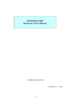


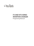
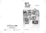
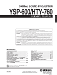
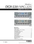
![SC450G 導電率変換器 [スタイル:S2]](http://vs1.manualzilla.com/store/data/006528460_2-777bddcbd7f006e5f45ca478d2d1b911-150x150.png)