1
Back
Installation Manual
UAIS TRANSPONDER
FA-150
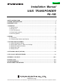
SAFETY INSTRUCTIONS .....................................................................................................................I
SYSTEM CONFIGURATIONS..............................................................................................................ii
EQUIPMENT LISTS ............................................................................................................................iii
1. MOUNTING ......................................................................................................................................1
1.1 Antenna Units............................................................................................................................1
1.2 Monitor Unit...............................................................................................................................8
1.3 UAIS Transponder...................................................................................................................10
1.4 Power Supply (option).............................................................................................................11
1.5 Pilot Plug (option)....................................................................................................................11
2. WIRING...........................................................................................................................................12
2.1 Connection ..............................................................................................................................12
2.2 Changing Ship’s Mains Specifications ....................................................................................16
3. SETTING AND ADJUSTMENT ......................................................................................................17
3.1 Inland AIS Specific Settings ....................................................................................................17
3.2 Setting MMSI, IMO No., Name and Call Sign .........................................................................20
3.3 Setting GPS Antenna Position ................................................................................................21
3.4 Setting Ship Type ....................................................................................................................22
3.5 Setting I/O Port........................................................................................................................22
4. ATTACHING LAN KIT (OPTION) ...................................................................................................27
5. IEC 61162-1/2 DATA SENTENCES................................................................................................31
APPENDIX 1 JIS CABLE.............................................................................................................. AP-1
PACKING LISTS...............................................................................................................................A-1
OUTLINE DRAWINGS .....................................................................................................................D-1
INTERCONNECTION DIAGRAM..................................................................................................... S-1
www.furuno.co.jp
All brand and product names are trademarks, registered trademarks or service marks of their respective holders.
The paper used in this manual
is elemental chlorine free.
・FURUNO Authorized Distributor/Dealer
9-52 Ashihara-cho,
Nishinomiya, 662-8580, JAPAN
Telephone : +81-(0)798-65-2111
Fax
: +81-(0)798-65-4200
All rights reserved.
Printed in Japan
A : NOV . 2004
E : SEP . 08, 2009
Pub. No. IME-44310-E
(DAMI )
FA-150
*00015008314*
*00015008314*
* 0 0 0 1 5 0 0 8 3 1 4 *
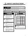
SAFETY INSTRUCTIONS
The installer must read the safety instructions before attempting to install this equipment.
WARNING
Indicates a potentially hazardous situation which, if not avoided,
could result in death or serious injury.
CAUTION
Indicates a potentially hazardous situation which, if not avoided,
can result in minor or moderate injury.
Warning, Caution
Mandatory Action
Prohibitive Action
WARNING
CAUTION
ELECTRICAL SHOCK HAZARD
Do not open the equipment unless
totally familiar with electrical
circuits and service manual.
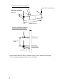
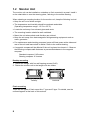
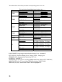
Observe the following compass safe
distances to prevent interference to a
magnetic compass:
Only qualified personnel should work
inside the equipment.
Turn off the power at the switchboard before beginning the
installation.
Fire or electrical shock can result if the
power is left on.
Do not install the equipment where it
may get wet from rain or water
splash.
Water in the equipment can result in
fire, electrical shock or damage the
equipment.
Be sure that the power supply is
compatible with the voltage rating of
the equipment.
Standard Steering
compass compass
FA-1501
UAIS Transponder
1.2 m
0.8 m
FA-1502
Monitor unit
0.45 m
0.3 m
GVA-100
0.3 m
0.3 m
DB-1
0.3 m
0.3 m
PR-240
0.9m
0.6 m
Attach securely protective earth to the
ship's body.
The protective earth is required to the
power supply to prevent electrical shock.
Connection of an incorrect power
supply can cause fire or damage the
equipment. The voltage rating of the
equipment appears on the label above
the power connector.
i
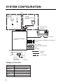
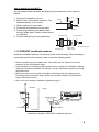
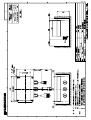
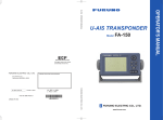
SYSTEM CONFIGURATION
Either
GPS antenna
GSC-001
GPA-017S
VHF antenna
GPS/VHF
combined antenna
GVA-100
Distributor unit
DB-1
MONITOR UNIT
FA-1502
UNIVERSAL AIS
MENU
DISP
ENT
DIM
NAV
STATUS
FA-150
PWR
12-24 VDC
UAIS TRANSPONDER
FA-1501
External display, NAVNET2, Pilot plug unit
Sensor
Alarm system
PC, BEACON RECEIVER
LAN
Blue Sign
Power supply
PR-240
: Standard
: Option
: Local supply
24 VDC
100-115/
200-230 VAC
1φ, 50/60Hz
12-24 VDC
Category of the units
GSC-001
GPA-017S
GVA-100
FA-1501
FA-1502
DB-1
PR-240
ii
Exposed to the weather
Exposed to the weather
Exposed to the weather
Protected from the weather
Protected from the weather
Protected from the weather
Protected from the weather
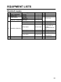
EQUIPMENT LISTS
Standard supply
No.
Name
1 UAIS Transponder
2 Monitor Unit
3
GPS Antenna
GPS/VHF Combined
4
5
6
Type
FA-1501
FA-1502
GSC-001
GPA-017S
GVA-100
MJ-A10SPF0012-050
CP24-00501
Code no.
000-150-216
005-955-550
Qty
1
1
CP24-00400
000-041-980
1
CP24-00101
CP24-00141
005-950-730
005-952-330
1
1
CP24-00502
005-955-560
1
FP14-02801
SP24-00101
004-366-960
-
1
1
1
Select one.
1
Cable for FA-1501
For FA-1501
For FA-1502
CP14-06001 &
Cable
MJ-A3SPF0013-0
35
For DB-1
For GVA-100
For GPA-017S/
GSC-00175
For FA-1502
For FA-1502
Installation Materials
Accessories
Spare Parts
Remarks
iii
Optional supply
No.
Name
1
Monitor unit
2
Antenna cable set
3
Antenna cable set
4
5
Coaxial cable
Mast mount fixture
Right-angle antenna
base
L-angle antenna
base
Antenna base for
rail mount
Whip antenna
Antenna fixing
bracket
Whip antenna
AC-DC power
supply
Pilot plug
AD-100
6
7
8
9
10
11
12
13
14
Type
FA-1502
CP20-02700
CP20-02710
CP24-00300
CP24-00310
TNC-PS-3D-15
CP20-01111
Code no.
004-381-160
004-381-170
000-041-938
000-041-939
000-133-670
004-365-780
No.13-QA330
000-803-239 For GSC-001
No.13-QA310
000-803-240 For GSC-001
No.13-RC5160
000-806-114 For GSC-001
FAB-151D
000-572-029 For Japan only
4-310071
000-572-184 For FAB-151D
150M-W2VN
000-113-498 For outside Japan
Include installation materials
CP24-00151*
000-053-911
For gyrocompass
PR-240
Remarks
8D-FB-CV(30m)+CP20-02701
8D-FB-CV(50m)+CP20-02701
8D-FB-CV(30m)+CP24-00301
8D-FB-CV(50m)+CP24-00301
TNC-TNC, 15m
For GSC-001
16
Flush mount kit S
Flush mount kit F
OP24-3
AD-100
MJ-A10SPF
0012-050
MJ-A10SPF
0012-100
MJ-A10SPF
0012-250
MJ-A10SPF
0012-500
MJ-A10SPF
0012-1000
OP20-17
OP20-29
17
ɸ 80 Mast mount kit
OP24-5
18
GPS antenna
GSC-001-FA-T
19
LAN kit
OP24-8
005-956-020 See page 27.
FAISPC MARK-2
005-860-470
FAISPC-MX-50
001-046-340 LAN kit required
15
20
21
iv
Cable assy.
UAIS display
software
AIS display software
CD
000-150-216 5m
000-150-217 10m
000-150-218 25m
Transponder-display,
connector attached at
one end
000-150-219 50m
000-150-220 100m
000-040-720
For monitor unit
000-041-405
005-954-510 For GVA-100
-
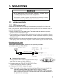
1. MOUNTING
NOTICE
Do not apply paint, anti-corrosive sealant or contact spray
to coating or plastic parts of the equipment.
Those items contain organic solvents that can damage coating
and plastic parts, especially plastic connectors.
1.1 Antenna Units
1.1.1 GPS antenna unit
Install the GPS antenna unit referring to the drawing on page D-5 or D-6 at the
back of this manual. When selecting a mounting location for the antenna, keep in
mind the following points.
• Select a location out of the radar beam. The radar beam will obstruct or prevent
reception of the GPS satellite signal.
• There should be no interfering object within the line-of-sight to the satellites. Objects
within line-of-sight to a satellite, for example, a mast, may block reception or prolong
acquisition time.
• Mount the antenna unit as high as possible to keep it free of interfering objects and
water spray, which can interrupt reception of GPS satellite signal if the water freezes.
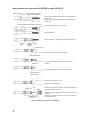
Extending antenna cable
Three types of antenna cable extensions are optionally available.
a) Antenna cable set CP20-02700
Conversion
Cable Assy.
NJ-JP-3DXV-1
Antenna Unit
: Connector
0.6m
Antenna Cable
FA-1501
30m
TNCP-NJ
1 m
Fabricate locally. (See next page.)
N-P-8DFB
Waterproofing connector
Wrap connector with vulcanizing tape and then vinyl
tape. Bind the tape end with a cable-tie.
b) Antenna cable set CP20-02710 (8D-FB-CV, 50m)
Connect the cable the same as a) above.
c) Cable type RG-10/UY (shipyard supply)
Waterproofing connector
Note: The length of this cable should be less than 20 m to prevent signal loss.
The coax. coupling cable assy.(type: NJ-TP+3DXV-1, code no.
000-123-809), coaxial connector(N-P-8DFB; supplied), vulcanizing tape
and vinyl tape are required. Fabricate both ends of the cable as shown in
the figure on the next page.
1
How to attach the connector N-P-8DFB for cable 8D-FB-CV
Outer Sheath
Armor
Dimensions in millimeters.
Inner Sheath Shield
50
Remove outer sheath and armor by the dimensions
shown left.
Expose inner sheath and shield by the dimensions
shown left.
30
Cover with heat-shrink tubing and heat.
Cut off insulator and core by 10mm.
10
30
Twist shield end.
Slip on clamp nut, gasket and clamp as shown left.
Clamp
Nut
Gasket Clamp
(reddish
brown)
Aluminum Foil
Fold back shield over clamp and trim.
Trim shield here.
Insulator
Cut aluminum foil at four places, 90° from one
another.
Fold back aluminum foil onto shield and trim.
Trim aluminum
tape foil here.
1
Expose the insulator by 1mm.
5
Expose the core by 5mm.
Pin
Clamp Nut
Shell
Solder through
the hole.
Slip the pin onto the conductor. Solder them together
through the hole on the pin.
Insert the pin into the shell. Screw the clamp nut into
the shell.
(Tighten by turning the clamp nut. Do not tighten by
turning the shell.)
How to attach connector N-P-8DFB
2
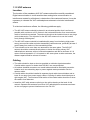
1.1.2 VHF antenna
Location
The location of the mandatory AIS VHF-antenna should be carefully considered.
Digital communication is more sensitive than analog/voice communication to
interference created by reflections in obstructions like masts and booms. It may be
necessary to relocate the VHF radiotelephone antenna to minimize interference
effects.
To minimise interference effects, the following guidelines apply:
• The AIS VHF antenna should be placed in an elevated position that is as free as
possible with a minimum of 0.5 meters in the horizontal direction from constructions
made of conductive materials. The antenna should not be installed close to any large
vertical obstruction. The objective for the AIS VHF antenna is to see the horizon
freely through 360 degrees.
• The AIS VHF antenna should be installed safely away from interfering high-power
energy sources like radar and other transmitting radio antennas, preferably at least 3
meters away from and out of the transmitting beam.
• There should not be more than one antenna on the same plane. The AIS VHF
antenna should be mounted directly above or below the ship’s primary VHF
radiotelephone antenna, with no horizontal separation and with a minimum of 2.8
meters vertical separation. If it is located on the same plane as other antennas, the
distance apart should be at least 10 meters.
Cabling
• The cable should be kept as short as possible to minimize signal attenuation.
Coaxial cables equal to or better than RG10U/Y are recommended.
• All outdoor-installed connectors on coaxial cables should be fitted with preventive
isolation such as vulcanizing tape to protect against water penetration into the
antenna cable.
• Coaxial cables should be installed in separate signal cable channels/tubes and at
least 10 cm away from power supply cables. Crossing of cables should be done at
right angles (90°). The minimum bend radius of the coaxial cable should be 5 times
the cable's outer diameter.
• Install the VHF whip antenna referring to the outline drawing at the back of this
manual. Separate this antenna from other VHF radiotelephone antennas as shown
on the next page to prevent interference to the FA-150.
3
Horizontal separation distance
Other VHF whip antenna
Whip antenna for AIS
(GPS/VHF combined
antenna)
More than 10 m
Vertical separation distance
More than
2.8 m
More than 0.5 m
• When coaxial cable RG-10/UY (shipyard supply) is used, attach the coaxial plug
M-P-7 (dockyard supply) as shown on the next page.
4
How to attach the plug M-P-7
Lay the coaxial cable and attach an M-type plug (if necessary) to the cable as
follows.
1. Remove the sheath by 30 mm.
2. Bare 23 mm of the center conductor. Trim
braided shield by 5 mm and tin.
3. Slide coupling ring onto cable.
4. Screw the plug assembly on the cable.
5. Solder plug assembly to braided shield
through solder holes. Solder contact sleeve
to conductor.
6. Screw coupling ring into plug assembly.
30 mm
Sheath
5 mm
2 mm
Conductor
Braided shield
Insulator
Plug assembly
Coupling ring
Contact sleeve
Solder both
sides of hole.
Cut conductor here.
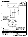
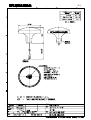
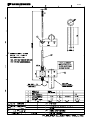
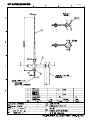
1.1.3 GPS/VHF combined antenna
Install the combined antenna unit referring to the outline drawing. When selecting a
mounting location for the antenna, keep in mind the following points.
• Select a location out of the radar beam. The radar beam will obstruct or prevent
reception of the GPS satellite signal.
• There should be no interfering object within the line-of-sight to the satellites. Objects
within line-of-sight to a satellite, for example, a mast, may block reception or prolong
acquisition time.
• Mount the antenna unit as high as possible. Mounting it this way keeps it free of
interfering objects and water spray, which can interrupt reception of GPS satellite
signal if the water freezes.
• Also, refer to the antenna installation guidelines page 3.
Outdoor
Indoor
Distributor DB-1
GPS
UAIS Transponder
VHF
N-P-8DFB
RG-10U/Y
N-P-8DFB
Installation overview of GPS/VHF combined antenna
5
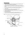
Mounting procedure
1. Dismount the bottom cover, cut the cable-tie inside the unit and take out the
coaxial connector attached to the combined box.
2. Loosen four screws to loosen whip antenna fixture and pull out the coaxial
connector coming from the combined box through the hole in the whip antenna
fixture.
3. Connect the coaxial connector to the whip antenna base and wrap the junction
part of the whip antenna with vulcanizing tape and then vinyl tape for
waterproofing.
4. Insert the whip antenna from the top of the combined antenna.
5. Secure the whip antenna with whip antenna fixture.
6. Using a new plastic band (supplied), secure the cables and coaxial connector
inside the antenna case.
7. Mount the bottom cover.
8. Fix the GPS/VHF combined antenna to the ship’s stanchion (40 to 50 mm
diameter) with antenna fixing brackets, flat washers and hex. nuts.
Note: Coat the exposed parts of bolts and nuts with silicon sealant.
Whip antenna fixture
Loosen four screws.
(M5x16)
Antenna fixing bracket
Combined box
Bottom cover
GPS/VHF Combined antenna
6
The top of the stanchion comes
into contact with the flange.
Stanchion
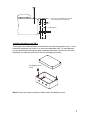
Installing distributor unit DB-1
The length of the cable between the distributor unit and transponder unit is 1 m so
locate the distributor unit within 1 m from the transponder unit. Fix the distributor
unit on the bulkhead, facing the cable entrance downward. Remove the lid of the
distributor unit and secure the unit with two self-tapping screws.
Self-tapping screw
(4x30)
Note: Be sure no foreign material or water enters the distributor unit.
7
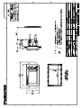
1.2 Monitor Unit
The monitor unit can be installed on a desktop or flush mounted in a panel. Install it
on the chart table or near the steering place, referring to the outline drawing.
When selecting a mounting location for the monitor unit, keep the following in mind:
• Keep the unit out of direct sunlight.
• The temperature and humidity should be moderate and stable.
(Operating temperature range: -15°C to +55°C)
• Locate the unit away from exhaust pipes and vents.
• The mounting location should be well ventilated.
• Mount the unit where shock and vibration are minimal.
• Keep the unit away from electromagnetic field generating equipment such as
motor, generator.
• For maintenance and checking purposes, leave sufficient space at the sides and
rear of the unit and leave slack in cables. Refer to the outline drawing.
• A magnetic compass will be affected if the unit is placed too close to it. Observe
the following compass safe distances to prevent disturbance to the magnetic
compass:
Standard compass: 0.45 meters
Steering compass: 0.3 meters
Desktop mounting
1. Fasten the hanger with four self-tapping screws (5x20).
2. Fasten the monitor unit to the hanger with two knobs.
Tabletop
Overhead
Flush mounting
There are two types of flush mount kits, F type and S type. For details, see the
outline diagrams at the back of this manual.
8
F type
Use the optional flush mount kit OP20-29.
Name
Type
Code No.
Qty
Cosmetic panel
20-016-1051
100-251-370-10
1
Self-tapping screw
5x20
000-162-609-10
4
Hexagon-head bolt
M6x12
000-162-897-10
2
Spring washer
M6
000-158-855-10
2
1. Prepare a cutout in the mounting location whose dimensions are 183 (W) x 92
(H) mm.
2. Attach the cosmetic panel (20-016-1051) to the unit with two hex head bolts
(M6x12) and two spring washers (M6).
3. Fix the unit to the mounting location with four self-tapping screws (5x20).
S type
Use the optional flush mount kit OP20-17.
.Name
Type
Code No.
Qty
Fixing plate
20-007-2401
100-183-190-10
2
Hexagon-head bolt
M6x12
000-162-897-10
2
Wing bolt
M4x30
000-804-799
4
Wing nut
M4
000-863-306
4
Spring washer
M6
000-158-855-10
2
1. Prepare a cutout in the mounting location whose dimensions are 167 (W) x 92
(H) mm.
2. Insert the unit to the cutout.
3. Attach two fixing plates (20-007-2401) to the unit with two hex bolts (M6x12)
and two spring washers (M6).
4. Screw four wing bolts (M4x30) to wing nuts (M4).
5. Fasten the unit with four wing bolts and nuts.
9
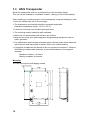
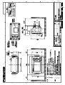
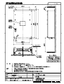
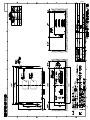
1.3 UAIS Transponder
Mount the transponder, where it is protected from rain and water splash.
This unit can be installed on a bulkhead. Install it, referring to the outline drawing.
When selecting a mounting location for the transponder, keep the following in mind:
• Keep the transponder out of direct sunlight.
• The temperature and humidity should be moderate and stable.
(Operating temperature range: -15°C to +55°C)
• Locate the unit away from exhaust pipes and vents.
• The mounting location should be well ventilated.
• Mount the unit where shock and vibration are minimal.
• Keep the unit away from electromagnetic field generating equipment such as
motor, generator.
• For maintenance and checking purposes, leave sufficient space at the sides and
rear of the unit and leave slack in cables. Refer to the outline drawing.
• A magnetic compass will be affected if the unit is placed too close to it. Observe
the following compass safe distances to prevent disturbance to the magnetic
compass:
Standard compass: 1.2 meters
Steering compass: 0.8 meters
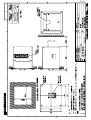
Mounting
● Fix the unit with four self-tapping screws.
7 Fixing holes
180
1
180
1
100
R3
.5
POWER
7
250
10
420
405
385
1
7.5
2-
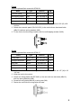
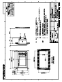
1.4 Power Supply (option)
When selecting a mounting location for the unit, keep the following in mind:
•
•
•
•
•
Keep the unit out away from areas subject to water splash.
Locate the unit away from exhaust pipes and vents.
The mounting location should be well ventilated.
Mount the unit where shock and vibration are minimal.
A magnetic compass will be affected if the unit is placed too close to it. Observe
the following compass safe distances to prevent disturbance to the magnetic
compass:
Steering compass: 0.6 m
Standard compass: 0.9 m
Fix the unit with four self-tapping screws (4x16) to a desktop or the deck as shown
in the figure below. It is not necessary to open the cover.
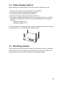
1.5 Pilot Plug (option)
The pilot plug should be mounted near where the pilot steers the ship. This plug is
used to connect a PC to display AIS information for use by the pilot. Refer to the
outline drawing at the back of this manual for mounting dimensions.
11
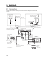
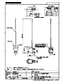
2. WIRING
2.1 Connection
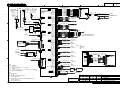
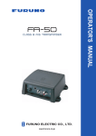
Connect the equipment, referring to the interconnection diagram at the back this
manual.
GPS Antenna
GSC-001 or
GPS-017S
150M-W2VN
or FAB-151D
GPS/VHF Conbined
Antenna GVA-100
Either one
0.6 m
Distributor unit
DB-1
*
0.8 m
*
*
RG-10U/Y
Attached to Distributor
(approx. 1m)
RG-10U/Y
8D-FB-CV, 30 m/50 m: Option
RG-10U/Y: Local supply
: Ground is not required.
Transponder unit
FA-1501
BREAKER
6.3A
VHF ANT
GPS ANT
PC
Power Supply
PR-240
AC DC DC
IN IN OUT
DPYC-1.5**
DPYC-2.5
IV-1.25sq
PC
MJ-A3SPF0013
3.5m
12-24 VDC
(Connect to the alternative
power source.)
12
Monitor unit
FA-1502
Other external device
(See next page.)
100/110/115/200/
220/230 VAC
*,**: See page 14.
Ground
IV-2.0sq
MJ-A10SPF0012
LAN 5/10/25/50/100m
IV-1.25sq
12-24 VDC
: Standard
: Option
: Local Supply
EXT ALM: Connect ship's alarm system.
DISP: Connect the monitor unit.
Blue Sign
COM1
COM2
DC (-)
COM3
COM4
DC (+)
COM5
COM6
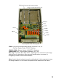
Internal ports of the Transponder
COM1: Long range communication device (Inmarsat C, etc.) or
External display (Radar, ECDIS, Pilotplug)
COM2 & COM3: External display, NAVNET 2, Pilot plug
COM4-COM6: GPS, Gyrocompass, Speedlog, ROT, etc.
Blue Sign: Connects a Blue Sign device, a lighting device mounted on the bridge
which gives off a blue light to warn oncoming vessels when your vessel is
navigating a channel in the reverse direction.
Note: A plastic sheet is placed across the cable glands of the transponder to keep
out foreign material. Cut out holes in the plastic where cables are to be lead in.
13
*: Waterproofing connectors
Wrap connector with vulcanizing tape and then vinyl tape. Bind the tape end with
a cable-tie.
Waterproofing connector
**: DPYC-2.5, TTYCS-1Q and TTYCS-4 are Japan Industry Standard cables.
Use them or the equivalents, referring to the Appendix.
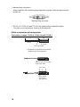
Cable connection at transponder
Fabrication of cables TTYCS-4, TTYCS-1Q and TTYCS-1
L
Shield
50
Remove paint
by 50 mm.
Cut vinyl sheath.
L: Depends on equipment connected.
Measure at the transponder.
Expose core and fold back
shield onto cable.
Vinyl tape
6
45
Lay in clamp
where paint
was removed.
14
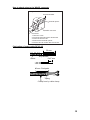
How to attach wires to the WAGO connector
Wiring for WAGO connector
Press downward.
Terminal opener
Wire
WAGO connector
Twist
Procedure
1. Twist the cores.
2. Press the terminal opener downward.
3. Insert the wire to hole.
4. Remove the terminal opener.
5. Pull the wire to confirm that it is secure.
Fabrication of power cable DPYC-2.5
50 mm
Armor
Vinyl sheath
6 to7 mm
40 mm: Peel paint.
Taping
Clamp here by cable clamp.
15
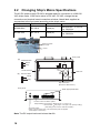
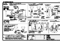
2.2
Changing Ship’s Mains Specifications
The AC-DC power supply PR-240 is shipped ready for connection to a 200-230
VAC ship’s mains. If the ship’s mains is 100 VAC-115 VAC, change the tap
connection and terminal board connection as below. Attach label supplied as
accessories to the front panel according to the ship’s mains.
Ship’s mains
Tap connection
Terminal board
Label
AC200-230V
SEL 230 V
Below (a)
200-230 VAC 2.5-2.0 A
1φ 50/60 Hz
AC100-115V
SEL 115 V
Below (b)
100-115 VAC 4.0-3.5 A
1φ 50/60 Hz
Remove screw
and cover.
Cover
Front panel
(a) 200-230 VAC
1
Black
2
3
Grey
Terminal board
(b) 100-115 VAC
1
Black
2
3
Grey
Relay
Coil
J4
1
2
3
4
5
6
7
8
3
2
1
SEL
115V
SEL
230V
Heat sink
Tap connection
(Pull out to disconnect.)
Front panel
Attach appropriate label.
AC FAIL:Connect to Alarm system.
Output Setting: Normal Open
Set plug to 1 & 2 pins of J4
Normal Close
Set plug to 2 & 3 pins of J4 (Factory setting)
(This setting is for serial no. 022736 and after.)
AC Power Switch
(When connecting DC input, note that the DC power is supplied
if this swqitch is turned off.)
Note: The DC output load must be less than 8A.
16
3. SETTING AND ADJUSTMENT
After installing the equipment, set up the own ship’s static information (MMSI, IMO
number, ship’s name, call sign, type of ship and GPS antenna position). Also, set
up the I/O ports.
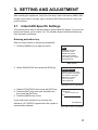
3.1
Inland AIS Specific Settings
This section shows how to activate and set up the Inland AIS feature. (If you do not
require this feature, go to section 3.2.) The installer obtains the AIS activation key
from the place of purchase.
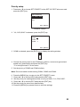
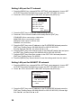
Entering activation key
Enter your key number to activate the Inland AIS.
1. Press the [MENU] key to open the menu.
[MENU]
MSG
SENSOR STATUS
INTERNAL GPS
USER SETTINGS
INITIAL SETTINGS
CHANNEL SETTINGS
DIAGNOSTICS
Main menu
2. Select DIAGNOTICS then press the [ENT] key.
[DIAGNOSTICS]
MONITOR TEST
TRANSPONDER TEST
PWR ON/OFF HISTORY
TX ON/OFF HISTORY
MEMORY CLEAR
ACTIVATE KEY
FOR SERVICE
DIAGNOSTICS sub-menu
3. Select ACTIVATE KEY then press the [ENT] key.
4. Press the [ENT] key, enter your activation key
then press the [ENT] key.
5. Press the [MENU] key to quit.
If you entered the activation key correctly, the
indication "ACTIVATED!" appears then the system is
automatically restarted.
[ACTIVATE KEY]
DEVICE ID
XX-XX-XX-XX-XX
KEY
- - -
QUIT[MENU]
ACTIVATE KEY sub-menu
17
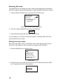
Selecting AIS mode
The Inland AIS has two operating modes: Inland (inland waterways) and SOLAS
(SOLAS compliant class A AIS transponder). Select INLAND AIS mode as follows:
1. Press the [NAV STATUS] key to open the NAV STATUS menu.
[NAV STATUS]
NAV STATUS:
15
AID MODE:
SOLAS
***STATUS DETAIL***
NOT DEFINED
(DEFAULT)
NAV STATUS menu (initial sub-menu)
2. Push ▼ to select AIS MODE then press the [ENT] key.
SOLASRX
INLAND
3. Select INLAND (Inland AIS) then press the [ENT] key.
You are asked if you are sure to reboot the system. Press◄ to select YES then
press the [ENT] key to reboot.
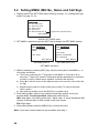
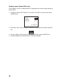
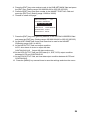
Setting blue sign status
Blue sign (a day-sign), which in combination with a white flashing light, must be
shown if you are sailing on the port-side shore (against traffic direction).
1. Press the [MENU] key to open the menu.
[MENU]
MSG
SENSOR STATUS
INTERNAL GPS
USER SETTINGS
INITIAL SETTINGS
CHANNEL SETTINGS
DIAGNOSTICS
Main menu
2. Press ▼ on the cursor pad to select INITIAL SETTINGS and press the [ENT]
key. The password entry window appears.
[ENTER PASSWORD]
Password entry window
18
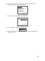
3. Enter the password to show the INITIAL SETTINGS menu. Note that the
password is known by only the FURUNO dealer.
[INITIAL SETTINGS]
SET MMSI
MMSI
SET
SET INT ANT POS.
SET EXT ANT POS.
SET SHIP TYPE
SET I/O PORT
SET BLUE SIGN SW
QUIT [MENU]
INITIAL SETTINGS menu
4. Select SET BLUE SIGN SW then press the [ENT] key.
[SET BLUE SIGN SW]
SET BLUE SIGN SW
NOT AVAILABLE
QUIT [MENU]
SET BLUE SIGN SW sub-menu
5. NOT AVAILABLE is selected; press the [ENT] key.
NOT AVAILABLE
AVAILABLE
6. Select NOT AVAILABLE (not in use) or AVAILABLE (in use) as applicable then
press the [ENT] key.
19
3.2 Setting MMSI, IMO No., Name and Call Sign
1. Display the INITIAL SETTINGS menu referring to step 1-3 in "Setting blue sign
status" on page 18 - 19.
[INITIAL SETTINGS]
SET MMSI
SET INT ANT POS.
SET EXT ANT POS.
SET SHIP TYPE
SET I/O PORT
SET BLUE SIGN SW
Appears for Inland AIS only
QUIT [MENU]
INITIAL SETTINGS menu
2. SET MMSI is selected; press the [ENT] key to display the SET MMSI window.
[SET MMSI]
MMSI: 000000000
IMO NO.: 000000000
NAME:
[SET MMSI]
MMSI: 000000000
NAME:
CALL SIGN:
IMO NO.: 000000000
ENI: 00000000
CALL SIGN:
QUIT [MENU]
SET MMSI (Class A)
QUIT [MENU]
SET MMSI (Inland AIS)
SET MMSI sub-menu
3. MMSI is selected; press the [ENT] key. Use the cursor pad to set MMSI no., in
nine digits, as follows:
a) The cursor is selecting the 1st digit place of the MMSI no. Press ▲ or ▼ to
select the 1st digit of the number. Pressing ▲ displays alphanumeric characters
cyclically in order of blank space, alphabet, numerals and symbols.
b) Press ► to shift the cursor to the adjacent place, then use ▲ or ▼ to select the
2nd digit.
c) Repeat steps a) and b) to finish entering the number. To erase a character,
insert a space.
d) After entering all digits, press the [ENT] key to register input.
4. Enter IMO number, name of your vessel and call sign, similar to how you
entered MMSI. For the Inland AIS, additionally enter ENI no.
IMO: Nine digits. If the IMO number has 7 digits, enter “0” twice followed by IMO
number. If the ship has no IMO number, enter nine zeroes.
ENI: Eight digits
5. After entering data, press the [MENU] key to close the menu.
Note: If you enter incorrect data, do the procedure from step 1.
20
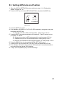
3.3 Setting GPS Antenna Position
1. Open the INITIAL SETTINGS window, referring to step 1-3 in "Setting blue
status" on page 18 - 19.
2. Press ▲ or ▼ key to choose SET INT ANT POS. and press the [ENT] key.
[SET INT ANT POS.]
A
B
A:
B:
C:
D:
0m
0m
0m
0m
C D
QUIT[MENU]
SET INT ANT POS. sub-menu
(Data entry)
3. Press the [ENT] key again.
4. Enter distance for location “A” of FA-150 GPS antenna by using the cursor pad
and press the [ENT] key.
A: Distance from bow to GPS antenna position, setting range: 0-511 m
5. Press the [ENT] key and enter distance for location B, C and D similar to how
you did for "A" above.
B: Distance from stern to GPS antenna position, setting range: 0-511 m
C: Distance from port to GPS antenna position, setting range: 0-63 m
D: Distance from starboard to GPS antenna position, the setting range: 0-63 m
6. Press the [MENU] key to return to the INITIAL SETTINGS menu.
7. Press ▲ or ▼ key to choose SET EXT ANT POS and press the [ENT] key.
8. Enter distance for location of an external GPS antenna (if connected) similar to
how you did for the internal GPS antenna.
9. Finally press the [MENU] key to save the settings.
21
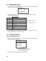
3.4 Setting Ship Type
1. In the INITIAL SETTINGS window, press the ▲ or ▼ key to choose the SET
SHIP TYPE and press the [ENT] key.
[SET SHIP TYPE]
TYPE NO :
0*
* * * * TYPE DETAIL * * * *
NOT AVAILABLE
2. Press the [ENT] key and set number for ship type by using ▲ or ▼ key,
referring to the table below.
Table: Ship type
No.
1
2
3
4
5
6
7
8
9
Ship type
Future use
WIG
Vessel
HSC
Special craft
Passenger ships
Cargo ships
Tanker
Other type of ship
WIG: Wing in ground
HSC: High speed craft
(For details, see “§1.5 Setting Up for Voyage” on the operator’s manual.)
3. Press the [MENU] key to save the setting.
3.5 Setting I/O Port
Setting COM port/PC port
1. In the INITIAL SETTINGS window, press ▲ or ▼ key to choose the SET I/O
PORT and press the [ENT] key.
[SET I/O PORT]
SET
COM PORT
COM1COM1
SET PC PORT
SET LAN PORT*1
SET PRIORITY
SET QUALITY*2
QUIT[MENU]
*1 Shown if fitted with LAN kit (option).
*2 Shown if Inland AIS is incorporated.
SET I/O PORT menu
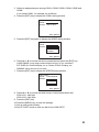
2. SET COM PORT is selected; press the [ENT] key.
22
3. Select an appropriate port among COM1, COM2, COM3, COM4, COM5 and
COM6.
If you chose COM1, for example, do as follows.
4. Press the [ENT] key to display the COM1 setting window.
[SET COM1]
MODE : LONG RANGE
SPEED: IEC 61162-2
QUIT [MENU]
5. Press the [ENT] key again to display the MODE setting window.
[SET COM1]
MODE : LONG RANGE
SPEED: LONG RANGE
EXT DISPLAY
DISABLE
QUIT [MENU]
6. Press ▲ or ▼ to choose the device connected and press the [ENT] key.
LONG RANGE: Long range communication device, for ex. Inmarsat C.
EXT DISPLAY: External display, for ex. Radar, ECDIS, Pilotplug, etc.
DISABLE: When the port is not used.
7. Press the [ENT] key to display the SPEED setting window.
[SET COM1]
MODE : LONG RANGE
SPEED: IEC 61162-2
IEC 61162-1
IEC 61162-2
QUIT [MENU]
8. Press ▲ or ▼ to choose the data format, or data transmission rate.
IEC61162-1: 4800 bps
IEC61162-2: 38.4 Kbps
9. Press the [ENT] key.
10. Press the [MENU] key to save the settings.
11. Set up other ports similarly.
12. Set PC PORT similar to how you did for the COM PORT.
23
The table below shows the ports and corresponding items to be set.
Port
COM1
COM2
COM3
COM4
COM5
COM6
PC
Port and data format/data transmission rate
External device (MODE) Format/Rate (SPEED)
LONG RANGE
IEC61162-1, IEC61162-2
EXT DISPLAY
IEC61162-1, IEC61162-2
DISABLE
EXT DISPLAY
IEC61162-1, IEC61162-2
MONITOR
IEC61162-1 (No use)
IEC61162-2
HI LEVEL IF
IEC61162-1 (No use)
IEC61162-2
DISABLE
EXT DISPLAY
IEC61162-1, IEC61162-2
MONITOR
IEC61162-1 (No use)
IEC61162-2
HI LEVEL IF
IEC61162-1 (No use)
IEC61162-2
DISABLE
SENSOR
IEC61162-1, IEC61162-2
EXT DISPLAY
IEC61162-1, IEC61162-2
DISABLE
SENSOR
IEC61162-1, IEC61162-2
SENSOR
IEC61162-1, IEC61162-2
AD-10
STANDARD
4800bps, 9600bps
19.2kbps, 38.4kbps, 57.6kbps
MONITOR
4800bps, 9600bps
19.2kbps, 38.4kbps, 57.6kbps
SERVICE
4800bps, 9600bps
19.2kbps, 38.4kbps, 57.6kbps
BEACON
4800bps
DISABLE
Note: Underline shows default.
LONG RANGE: Long range communication device, for ex. Inmarsat C.
EXT DISPLAY: External display, for ex. Radar, ECDIS, Pilotplug, etc.
SENSOR: GPS, Gyrocompass, Speedlog, ROT, etc.
HI LEVEL IF: NAVNET 2
STANDARD (PC port): PC for inputting NMEA data (Same data as EXT DISPLAY).
MONITOR (PC port): PC having the FURUNO software FAISPC MK-2.
SERVICE (PC port): Service use FAISPC MK-2-equipped PC.
24
Priority setup
1. Press ▲ or ▼ to choose SET PRIORITY at the SET I/O PORT sub-menu and
press the [ENT] key.
[SET PRIORITY]
L/L, COG, SOG
HDG
ROT
QUIT [MENU]
PRIORITY menu
2. "L/L, COG, SOG" is selected; press the [ENT] key.
[SET L/L, COG, SOG]
COM4: 1
COM5: 2
COM6: 3
QUIT [MENU]
3. COM4 is selected; press the [ENT] key to display the setting window.
1
2
3
4. Choose the priority level for the COM4 port (position, course over ground and
speed over ground data) and press the [ENT] key.
"1" is the highest and "3" is the lowest.
5. Set the priority of COM5 and COM6 similarly.
Note: Do not set same number among COM4, COM5 and COM6.
6. Press the [MENU] key to return to the SET PRIORITY menu.
7. Press ▲ or ▼ to choose HDG and press the [ENT] key.
8. Set the priority for heading data similar to how you did for “L/L, COG, SOG”.
9. Press ▲ or ▼ to choose ROT and press the [ENT] key.
10. Set the priority for rate-of-turn data similarly.
11. Press the [MENU] key several times to save the settings.
25
Quality setup (Inland AIS only)
If your speed, course or heading sensor is type approved, choose quality setting as
shown below.
1. Press▼ to choose SET QUALITY at the SET I/O PORT sub-menu then press
the [ENT] key.
[SET QUALITY]
SPEED
COURSE
HEADING
: LOW
: LOW
: LOW
QUIT[MENU]
2. Press ▲ or ▼ to choose SPEED, COURSE or HEADING then press the [ENT]
key.
LOW
HIGH
3. Choose LOW or HIGH (quality index) applicable then press the [ENT] key.
4. Press the [MENU] key several times to save the settings.
26
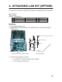
4. ATTACHING LAN KIT (OPTION)
To connect to PC network or NAVNET 3D network, the optional LAN kit is required.
Name: LAN kit
Type: OP24-8
Code no.: 005-956-020
Name
1 NET100 board
2 Hex. spacer
Code no.
008-535-840
000-801-678
Qty
1
4
Remark
03P9332
Attaching
1. Dismount the bottom cover.
2. Attach NET100 board 03P9332 to the 24P0035 board, referring to the figure
shown below.
Use screws removed in left figure.
NET Board03
03P9332
Spacer
J9
J9
24P0035
Unfasten 4 screw
24P0035
SW3
Transponder (Bottom cover removed)
Attaching 03P9332
3. Set DIP switch SW3 #4 as follows.
• For NAVNET 3D network: SW3 #4 OFF (default)
• For PC network: SW3 #4 ON
27
Setting LAN port for PC network
1. Press the [MENU] key, choose INITIAL SETTING, enter password, choose SET
I/O PORT and press the [ENT] key to show the SET I/O PORT sub menu.
2. Press ▲ or ▼ to choose SET LAN PORT and press the [ENT] key.
[SET LAN PORT]
MODE : STANDARD
IP ADDRESS
172. 031. 024. 001
SUB NET MASK
255. 255. 000. 000
PORT NO. : 10000
QUIT [MENU]
3. Press the [ENT] key to show the mode selecting window.
4. Press ▲ or ▼ to choose suitable mode and press the [ENT] key.
STANDARD: When connecting a LAN device
MONITOR: When connecting a monitor
SERVICE: Data output for service man
DISABLE: No connection
5. Press the [ENT] key, enter IP address in the IP ADDRESS field and press the
[ENT] key. (Setting range: 000.000.000.000 to 255.255.255.255)
Choose digit with ◄ or ►; set value with ▲ or ▼.
6. Press the [ENT] key, enter sub net mask in the SUB NET MASK field and press
the [ENT] key. (Setting range: 000.000.000.000 to 255.255.255.255)
7. Press the [ENT] key, enter port number in the PORT NO. field and press the
[ENT] key. (Setting range: 0 to 65535)
8. Press the [MENU] key several times to save the settings and close the menu.
Setting LAN port for NAVNET 3D network
1. Press the [MENU] key, choose INITIAL SETTING, enter password, choose SET
I/O PORT and press the [ENT] key to show the SET I/O PORT sub menu.
2. Press ▲ or ▼ to choose SET LAN PORT and press the [ENT] key.
[SET LAN PORT]
1/2
IP ADDRESS
172. 031. 024. 001
SUB NET MASK
255. 255. 000. 000
NAVNET PORT NO.
10000
3. Press the [ENT] key, enter IP address in the IP ADDRESS field and press the
[ENT] key. (Setting range: 000.000.000.000 to 255.255.255.255) Choose digit
with ◄ or ►; set value with ▲ or ▼.
28
4. Press the [ENT] key, enter sub net mask in the SUB NET MASK field and press
the [ENT] key. (Setting range: 000.000.000.000 to 255.255.255.255)
5. Press the [ENT] key, enter port number in the NAVNET PORT NO. field and
press the [ENT] key. (Setting range: 10000 to 30000)
6. Press▼ to show next page.
[SET LAN PORT]
2/2
GATEWAY ADDRESS
000. 000. 000. 000
HOST NAME : AISO
AISOUTPUT : CONTINUOUS
GPSOUTPUT : AUTO
ZDAOUTPUT : AUTO
7. Press the [ENT] key, enter gateway address in the GATEWAY ADDRESS field
and press the [ENT] key. (Setting range: 000.000.000.000 to 255.255.255.255)
8. At the HOST NAME field, enter host name that is used in the NAVNET
3D(Setting range: AIS 0 to AIS 9) .
9. At the AIS OUTPUT field, set output condition.
AUTO: Auto-detect of where to output AIS data.
CONTINUOUS: AIS Output AIS data continuously.
10. At the GPS OUTPUT field, set GPS data (L/L, SOF, COG) output condition
between AUTO and CONTINUOUS.
11. At the ZDA OUTPUT field, set time data output condition between AUTO and
CONTINUOUS.
12. Press the [MENU] key several times to save the settings and close the menu.
29
This page intentionally left blank.
30
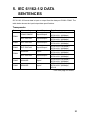
5. IEC 61162-1/2 DATA
SENTENCES
IEC 61162-1/2 format data is input or output from the data port COM1-COM6. The
table below shows the input/output data specifications.
Transponder
Port
Menu setting
Input/Output
LONG RANGE
Input/Output*
EXT DISPLAY
Input/Output*
COM2
EXT DISPLAY
Input/Output*
COM3
EXT DISPLAY
Input/Output*
SENSOR
Input*
EXT DISPLAY
Input/Output*
COM5
SENSOR
Input*
COM6
SENSOR
Input*
COM1
COM4
Data format
IEC61162-2 (38.4kbps) /
IEC61162-1 (4800bps)
IEC61162-2 (38.4kbps) /
IEC61162-1 (4800bps)
IEC61162-2 (38.4kbps) /
IEC61162-1 (4800bps)
IEC61162-2 (38.4kbps) /
IEC61162-1 (4800bps)
IEC61162-2 (38.4kbps) /
IEC61162-1 (4800bps)
IEC61162-2 (38.4kbps) /
IEC61162-1 (4800bps)
IEC61162-2 (38.4kbps) /
IEC61162-1 (4800bps)
IEC61162-2 (38.4kbps) /
IEC61162-1 (4800bps)
AD-10
*: See next page for details.
31
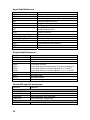
Input data/Sentences
Sentence (Priority)
ABM
ACA
ACK
AIR
BBM
VSD
LRI
LRF
DTM
GNS>GLL>GGA>RMC
VBW>RMC>VTG>OSD
RMC>VTG>OSD
HDT>OSD>AD-10 format
GBS
ROT>Calculated value
SSD
Contents
Addressed binary and safety related message
AIS regional channel assignment message
Acknowledge alarm
AIS interrogation request
UAIS broadcast binary message
UAIS voyage static data
Long Range interrogation
Long Range function
Datum reference
Position
Speed over ground
Course over ground
Heading
GNSS satellite fault detection
Rate of turn
UAIS ship static data
Output data/Sentences
Sentence
AIVDM
AIVDO
AIABK
AILRF
AILR1
AILR2
AILR3
AIACA
AIALR
AITXT
AIACS
Contents
VHF data-link message
UAIS VHF data-link own-vessel report
UAIS addressed and binary broadcast acknowledgement
Long-range function
Long-range reply with destination for function request “A”
Long-range reply for function requests “B, C, E and F”
Long-range reply for function requests “I, O, P, U and W”
AIS regional channel assignment message
Set alarm state
Text transmission
Channel management information source
Inland AIS specific sentences
Sentence
Input
PIWWIVD
PIWWSPW
PIWWSSD
PIWWVSD
Output
PIWWSPR
32
Contents
Inland waterway voyage data
Inland AIS security password
Inland waterway static ship data
Inland waterway voyage data
Inland AIS security password response
5'.(6#22+0)5%4'9
㩎㩡㩇㩊㨹㩕㩩㩧㩒㩆㩨ޓ㩆㨷
ฬޓޓ⒓
0#/'
%1&'
01
:575
㧲㨁㧾㨁㧺㧻ޓ㧱㧸㧱㧯㨀㧾㧵㧯ޓ㧯㧻ޓ㧚㧘㧸㨀㧰
㧔⇛࿑ߩኸᴺߪޔෳ⠨୯ߢߔ&ޓޕ+/'05+105+0&4#9+0)(144'('4'0%'10.;㧕
#%:
ဳᑼ㩄㨺㩎㩨⇟ภ߇㧞Ბߩ႐วޔਅᲑࠃࠅᲑߦઍࠊࠆㆊᷰᦼຠߢࠅޔ߅ߥޓޕߔ߹ߡߞ߇߆ࠄߜߤޔຠ⾰ߪᄌࠊࠅ߹ߖ
ࠎޕ
6916;2'5#0&%1&'5/#;$'.+56'&(14#0+6'/6*'.19'4241&7%6/#;$'5*+22'&+02.#%'1(6*'722'4
241&7%637#.+6;+56*'5#/'
⇟ภ
01
5'.(6#22+0)5%4'9
㩎㩡㩇㩊㨹㩕㩩㩧㩒㩆㩨ޓ㩆㨷
ฬޓޓ⒓
0#/'
⇛ޓޓ࿑
176.+0'
ဳฬ㧛ⷙᩰ
&'5%4+26+105
%2
%1&'01
:575
6;2'
%1&'01
ᢙ㊂
36;
↪ㅜ㧛⠨
4'/#4-5
#%: A-2
㧲㨁㧾㨁㧺㧻ޓ㧱㧸㧱㧯㨀㧾㧵㧯ޓ㧯㧻ޓ㧚㧘㧸㨀㧰
㧔⇛࿑ߩኸᴺߪޔෳ⠨୯ߢߔ&ޓޕ+/'05+105+0&4#9+0)(144'('4'0%'10.;㧕
#%:
6916;2'5#0&%1&'5/#;$'.+56'&(14#0+6'/6*'.19'4241&7%6/#;$'5*+22'&+02.#%'1(6*'722'4241&7%6
37#.+6;+56*'5#/'
ဳᑼ㩄㨺㩎㩨⇟ภ߇㧞Ბߩ႐วޔਅᲑࠃࠅᲑߦઍࠊࠆㆊᷰᦼຠߢࠅޔ߅ߥޓޕߔ߹ߡߞ߇߆ࠄߜߤޔຠ⾰ߪᄌࠊࠅ߹ߖࠎޕ
⇟ภ
01
+056#..#6+10/#6'4+#.5
↪ㅜ㧛⠨
4'/#4-5
+056#..#6+10/#6'4+#.5
ᢙ㊂
36;
#%: Ꮏ᧚ᢱ
ဳฬ㧛ⷙᩰ
&'5%4+26+105
%2
6;2'
Ꮏ᧚ᢱ
⇛ޓޓ࿑
176.+0'
%1&'01
A-1
+056#..#6+10/#6'4+#.5
70+6
176.+0'
%2
/575
/575
%8*6
%8*6
02&($ᐳ㊄
&$
)8#
&'5%4+26+10%1&'ͳ
##: 36;
A-3
䋨⇛࿑䈱ኸᴺ䈲䇮ෳ⠨୯䈪䈜䇯㩷㩷㪛㪠㪤㪜㪥㪪㪠㪦㪥㪪㩷㪠㪥㩷㪛㪩㪘㪮㪠㪥㪞㩷㪝㪦㪩㩷㪩㪜㪝㪜㪩㪜㪥㪚㪜㩷㪦㪥㪣㪰㪅䋩
##:
㪫㪮㪦㩷㪫㪰㪧㪜㪪㩷㪘㪥㪛㩷㪚㪦㪛㪜㪪㩷㪤㪘㪰㩷㪙㪜㩷㪣㪠㪪㪫㪜㪛㩷㪝㪦㪩㩷㪘㪥㩷㪠㪫㪜㪤㪅㩷㩷㪫㪟㪜㩷㪣㪦㪮㪜㪩㩷㪧㪩㪦㪛㪬㪚㪫㩷㪤㪘㪰㩷㪙㪜㩷㪪㪟㪠㪧㪧㪜㪛㩷㪠㪥㩷㪧㪣㪘㪚㪜㩷㪦㪝㩷㪫㪟㪜㩷㪬㪧㪧㪜㪩㩷
㪧㪩㪦㪛㪬㪚㪫㪅㩷㪨㪬㪘㪣㪠㪫㪰㩷㪠㪪㩷㪫㪟㪜㩷㪪㪘㪤㪜㪅
ဳᑼ㪆䍘䍎䍢䍼⇟ภ䈏䋲Ბ䈱႐ว䇮ਅᲑ䉋䉍Ბ䈮ઍ䉒䉎ㆊᷰᦼຠ䈪䈅䉍䇮䈬䈤䉌䈎䈏䈦䈩䈇䉁䈜䇯䇭䈭䈍䇮ຠ⾰䈲ᄌ䉒䉍䉁䈞䉖䇯
*':076
ⷺ㩏㨹㩎ޓ㧝⒳
(.#69#5*'4
㩚㩀㩨㩁ᐔᐳ㊄
2.#56+%$#0&
㩄㩧㩗㩨㨹㩂㩇
%100'%614
㩄㩒㩂㩊
0
#06'00#(+:+0)$4#%-'6
㨻㩧㩍㩏ขઃ㊄ౕ
Ꮏ᧚ᢱ
&+564+$76'470+6
ಽ㈩ེ
)258*(%1/$+0''00#
ⶄวⓨਛ✢ㇱ
࡙࠾࠶࠻
0#/'
)8#
)8#↪㧕
㧼㧭㧯㧷㧵㧺㧳ޓ㧸㧵㧿㨀
5'.($10&+0)6#2'
⛘✼㩍㨺㩖㩩
%100'%614
㩄㩒㩂㩊
60%0
%100'%614
㩄㩒㩂㩊
%108'46%#$.'#55;
ᄌ឵㩃㨺㩖㩨㩣⚵ຠ
8+0;.6#2'
㩕㩨㩐㩣㩍㨺㩖㩩01
ฬޓޓ⒓
0#/'
⇛ޓޓ࿑
176.+0'
%1&'
01
7㩍㨺㩖㩩ޓ::/
%1&'
01
60%20,
%1&'
01
02&5(#
%1&'
01
0,62&:8
%1&'
01
::㩂㩥㨾㩇㩥㩧
ဳฬ㧛ⷙᩰ
&'5%4+26+105
%2
6;2'
ᢙ㊂
36;
↪ㅜ㧛⠨
4'/#4-5
#%: 㧲㨁㧾㨁㧺㧻ޓ㧱㧸㧱㧯㨀㧾㧵㧯ޓ㧯㧻ޓ㧚㧘㧸㨀㧰
㧔⇛࿑ߩኸᴺߪޔෳ⠨୯ߢߔ&ޓޕ+/'05+105+0&4#9+0)(144'('4'0%'10.;㧕
#%:
ဳᑼ㩄㨺㩎㩨⇟ภ߇㧞Ბߩ႐วޔਅᲑࠃࠅᲑߦઍࠊࠆㆊᷰᦼຠߢࠅޔ߅ߥޓޕߔ߹ߡߞ߇߆ࠄߜߤޔຠ⾰ߪᄌࠊࠅ߹ߖ
ࠎޕ
6916;2'5#0&%1&'5/#;$'.+56'&(14#0+6'/6*'.19'4241&7%6/#;$'5*+22'&+02.#%'1(6*'722'4
241&7%637#.+6;+56*'5#/'
⇟ภ
01
+056#..#6+10/#6'4+#.5
Ꮏ᧚ᢱ
%1&'01
A-4
5'.(6#22+0)5%4'9
㩏㩗㩨㩊㨹㩕㩩㩧㩒㩆㩨㩆㨷
⇛ޓޓ࿑
176.+0'
%1&'
01
:575
ဳฬ㧛ⷙᩰ
&'5%4+26+105
ᢙ㊂
36;
↪ㅜ㧛⠨
4'/#4-5
㧲㨁㧾㨁㧺㧻ޓ㧱㧸㧱㧯㨀㧾㧵㧯ޓ㧯㧻ޓ㧚㧘㧸㨀㧰
㧔⇛࿑ߩኸᴺߪޔෳ⠨୯ߢߔ&ޓޕ+/'05+105+0&4#9+0)(144'('4'0%'10.;㧕
##:
ဳᑼ㩄㨺㩎㩨⇟ภ߇㧞Ბߩ႐วޔਅᲑࠃࠅᲑߦઍࠊࠆㆊᷰᦼຠߢࠅޔ߅ߥޓޕߔ߹ߡߞ߇߆ࠄߜߤޔຠ⾰ߪᄌࠊࠅ߹ߖ
ࠎޕ
6916;2'5#0&%1&'5/#;$'.+56'&(14#0+6'/6*'.19'4241&7%6/#;$'5*+22'&+02.#%'1(6*'722'4
241&7%637#.+6;+56*'5#/'
ฬޓޓ⒓
0#/'
%18'4
⼔㩀㩔㩨㨺
ฬޓޓ⒓
0#/'
⇛ޓޓ࿑
176.+0'
ဳฬ㧛ⷙᩰ
&'5%4+26+105
(2
%1&'
01
41*5
6;2'
%1&'01
ᢙ㊂
36;
↪ㅜ㧛⠨
4'/#4-5
#%: A-6
㧲㨁㧾㨁㧺㧻ޓ㧱㧸㧱㧯㨀㧾㧵㧯ޓ㧯㧻ޓ㧚㧘㧸㨀㧰
㧔⇛࿑ߩኸᴺߪޔෳ⠨୯ߢߔ&ޓޕ+/'05+105+0&4#9+0)(144'('4'0%'10.;㧕
#%:
ဳᑼ㩄㨺㩎㩨⇟ภ߇㧞Ბߩ႐วޔਅᲑࠃࠅᲑߦઍࠊࠆㆊᷰᦼຠߢࠅޔ߅ߥޓޕߔ߹ߡߞ߇߆ࠄߜߤޔຠ⾰ߪᄌࠊࠅ߹ߖ
ࠎޕ
6916;2'5#0&%1&'5/#;$'.+56'&(14#0+6'/6*'.19'4241&7%6/#;$'5*+22'&+02.#%'1(6*'722'4
241&7%637#.+6;+56*'5#/'
⇟ภ
01
#%%'5514+'5
⇟ภ
01
+056#..#6+10/#6'4+#.5
##: ઃዻຠ
%2
6;2'
Ꮏ᧚ᢱ
%1&'01
A-5
(75'
㩕㨷㨺㩇㩨
()$1##
#%8
()$#8
#2$(
2'4
8'5
#%: ဳᑼ㩄㨺㩎㩨⇟ภ߇㧞Ბߩ႐วޔਅᲑࠃࠅᲑߦઍࠊࠆㆊᷰᦼຠߢࠅޔ߅ߥޓޕߔ߹ߡߞ߇߆ࠄߜߤޔຠ⾰ߪᄌ
ࠊࠅ߹ߖࠎޕ
6916;2'5#0&%1&'5/#;$'.+56'&(14#0+6'/6*'.19'4241&7%6/#;$'5*+22'&+02.#%'1(6*'
722'4241&7%637#.+6;+56*'5#/'
5'652'4
8'55'.
$1:012
4'/#4-5%1&'01
#%:
52#4'
㧔⇛࿑ߩኸᴺߪޔෳ⠨୯ߢߔ&ޓޕ+/'05+105+0&4#9+0)(ޓ144'('4'0%'10.;㧕
&9)01
2'4
5'6
914-+0)
37#06+6;
75'
52
6;2'
&9)01
14
6;2'01
(74701'.'%64+%%1.6&
176.+0'
52#4'2#465.+56(14
0#/'1(
2#46
/(450#/'
+6'/
01
5*+201
%1&'01
A-7
CP20-02710 (004-381-170)
CP20-02700 (004-381-160)
Antenna Cable Set
A-8
CP20-00310 (000-041-939)
CP20-00300 (000-041-938)
Antenna Cable Set
A-9
Y. Hatai
D-1
Y. Hatai
D-2
Y. Hatai
D-3
D-4
Y. Hatai
D-5
Mar,27'07 R.Esumi
D-6
May 20 '03
D-7
Feb.22'05
Jan. 9, '03
D-8
5/Feb/09 R.Esumi
D-9
D-10
Feb.02'05
D-11
Nov.28'03
Oct.02'03
D-12
D-13
Y. Hatai
1
A
150M-W2VN
*2
OR
FAB-151D
GSC-001
選択
SELECT
0.2m(GPA-017S)
0.6m(GSC-001)
複合空中線部
GPS/VHF ANTENNA
GVA-100
2
VHFアンテナ
VHF ANTENNA
150M-W2VN
*2
OR
FAB-151D
GPSアンテナ
GPS ANTENNA
GPA-017S
OR
GSC-001
*1
RG-10/UY
M-P-7
TNC-J-3
3
M-P-7
N-P-8DFB
トランスポンダ部
TRANSPONDER UNIT
FA-1501
VHF ANT
1
2
3
4
5
6
7
8 *3
COM2_TD_A
COM2_TD_B
GND_ISO
COM2_RD_A
COM2_RD_B
GND_ISO
COM2_JP
COM2_JP
1
2
3
4
5
6
7
8
COM3_TD_A
COM3_TD_B
GND_ISO
COM3_RD_A
COM3_RD_B
GND_ISO
COM3_JP
COM3_JP
1
2
3
4
5
6
7
8 *3
COM4_TD_A
COM4_TD_B
GND_ISO
COM4_2_RD_A
COM4_2_RD_B
GND_ISO
COM4_JP
COM4_JP
COM4_1_RD_H
COM4_1_RD_C
1
2
3
4
5
6
7
8 *3
9
10
COM5_TD_A
COM5_TD_B
GND_ISO
COM5_2_RD_A
COM5_2_RD_B
GND_ISO
COM5_JP
COM5_JP
COM5_1_RD_H
COM5_1_RD_C
1
2
3
4
5
6
7
8 *3
9
10
COM6_TD_A
COM6_TD_B
GND_ISO
COM6_2_RD_A
COM6_2_RD_B
GND_ISO
COM6_JP
COM6_JP
COM6_1_RD_H
AD_DATA_H
COM6_1_RD_C/AD_DATA_C
AD_CLK_H
AD_CLK_C
1
2
3
4
5
6
7
8 *3
9
10
11
12
13
ANT
E
N-P-8DFB
GPS ANT
8D-FB-CV,30/50m *2
RG-10/UY,MAX.20m *1
N-J-3
COM2
M-P-3
1m
1m
VHF ANT
分配器
DISTRIBUTOR
TNC-P-3
DB-1
1m
GPS ANT
B
BLUESIGN
*1
TTYCS-1,MAX.100m
PC
FM14-7P
DATA
1
DGPSビーコン受信機 SD
DGPS BEACON
GND 7
RECEIVER
GR-80
1
2
3
4
5
6
7
8
NC
NC
NC
BLUESIGN-H
BLUESIGN-C
NC
NC
NC
*3
PC
Dsub9P
RS-232C CABLE
1 NC
(MAX.15m)
2 PC_SD
3 PC_RD
4 DTR
5 0V
6 DSR
7 RTS
8 CTS
9 NC
C
12-24VDC
100-115/
*1
200-230VAC DPYC-1.5
1φ,50/60Hz
*1
DPYC-2.5
24VDC
BLUESIGN
POWER
1 DC(+)
2 DC(-)
DPYC-2.5 *1
COM3
COM4
COM5
AC/DC電源ユニット +
AC/DC POWER + SUPPLY UNIT
E
*2
- PR-240
PE 保護アース
IV-2sq. *1
PC
D
*1 RJ45
STP CABLE(CAT5)
注記
*1)造船所手配
*2)オプション
*3)IEC61162-2使用時はジャンパーを追加する。
*4)AMP社製
*5)ジャイロにIEC61162インターフェイスがないときのみ接続可能。
*6)使用しない芯線は絶縁する。
NOTE:
*1: SHIPYARD SUPPLY
*2: OPTION
*3: ADD JUMPER WHEN USING IEC61162-2.
*4: PRODUCED BY AMP INC.
*5: GYRO CONVERTOR IS AVAILABLE WHEN GYROCOMPASS HAS NO
IEC61162 INTERFACE.
*6: INSULATE UNUSED WIRES.
1
2
3
4
5
6
7
8
LAN
*2
TXP
TXN
RXP
NC
NC
RXN
NC
NC
03P9332
COM6
EXT ALM
ALM_A
ALM_B
ALM_C
ACK_H
ACK_C
1
2
3
4
5
5
MJ-A10SPF0012,5m,φ8.9
MJ-A10SPF COM
(10m/25m/50m/100m,OPTION)
キ/アカ YEL/RED
1 TX_A
P
キ/クロ YEL/BLK
2 TX_B
シロ/アカ WHT/RED
3 RX_A
モモ/アカ PNK/RED
4 RX_B
P P
モモ/クロ PNK/BLK
5 SW_H
シロ/クロ WHT/BLK
6 SW_L
ハイ/アカ GRY/RED
7 0V
P
ハイ/クロ GRY/BLK
8 0V
*1
9 NC
TTYCS-4,MAX.100m
TD-A
10 FG
P
TD-B RADAR/ECDIS
RD-A (IEC61162-1/2)
RD-B
P
GND
1
2
3
4
5
6
7
8
COM1_TD_A
COM1_TD_B
GND_ISO
COM1_RD_A
COM1_RD_B
GND_ISO
COM1_JP
COM1_JP
COM1
NJ-TP-3DXV,1m
8D-FB-CV,30/50m *2
RG-10/UY,MAX.20m *1
N-P-8DFB
N-P-8DFB
N-J-3 0.8m
TNCP-NJ
DISP
DISP_TD_A
DISP_TD_B
GND_ISO
DISP_RD_A
DISP_RD_B
GND_ISO
DISP_SW(+)
DISP_SW(-)
4
S-1
6
表示部
MONITOR UNIT
FA-1502
POWER
DC_IN+
DC_INFG
1
2
3
FUSE
MJ-A3SPF
3A
WHT シロ
BLK クロ
MJ-A3SPF0013,3.5m,φ6.8
*2
PR-240
GND *1
IV-1.25sq.
12-24VDC
DPYC-1.5 *1
DPYC-2.5 *1
100-115/200-230VAC
1φ,50/60Hz
24VDC
PE 保護アース
IV-2sq. *1
*6
*1
TTYCS-4,MAX.100m
TD-A
TD-B RADAR/ECDIS
RD-A (IEC61162-1/2)
RD-B
GND
P
P
パイロットプラグユニット
PILOT PLUG UNIT
*4
OP24-3 *2 206486-1 206485
TX A 1
1
TX B 4
2
RX A 5
3
RX B 6
4
SHIELD 9
5
*6
*3
*1
TTYCS-4,MAX.30m
P
P
PC
COM1~COM3は等価に使用可能
COM1~COM3 USED EQUIVALENT
*6
*1
TTYCS-4,MAX.100m
EXT DISPLAY
(IEC61162-1/2)
OR
SENSOR
(IEC61162-2)
P
*1
TTYCS-1Q,MAX.100m
P
*6
OR
*1
TTYCS-1,MAX.100m
SENSOR: GPS
GYROCOMPASS
SENSOR
SPEED LOG
(IEC61162-1)
ROT
*1
TTYCS-1Q,MAX.100m
*6
*1
TTYCS-1,MAX.100m
*1
TTYCS-1,MAX.100m
*1
TTYCS-1Q,MAX.10m
(NORMAL OPEN)
(NORMAL CLOSE)
DISP_SW(+) 7
DISP_SW(-) 8
MJ-A10SPF0012,5/10/25/50/100m,φ9
ハイ/アカ GRY/RED
MJ-A10SPF
ハイ/クロ GRY/BLK
1
2
3
4
5
6
7
8
9
10
TD_A
TD_B
GND_ISO
RD_A
RD_B
GND_ISO
1
2
3
4
5
6
7
8
P
P
P
キ/アカ YEL/RED
キ/クロ YEL/BLK
シロ/アカ WHT/RED
モモ/アカ PNK/RED
モモ/クロ PNK/BLK
シロ/クロ WHT/BLK
*6
COM
TX_A
TX_B
RX_A
RX_B
SW_H
SW_L
0V
0V
NC
FG
表示部
MONITOR UNIT
FA-1502
GYROCOMPASS
AD-100
*1
TTYCS-1Q,MAX.100m
P
COM2/COM3
SENSOR
(IEC61162-2)
OR
SENSOR
(IEC61162-1)
*5
No.2 MONITOR UNIT
DISP
SENSOR
(IEC61162-1)
*1
TTYCS-1Q,MAX.100m
*6
No.2 表示部
SENSOR
(IEC61162-2)
OR
ALARM SYSTEM
DRAWN
23/Feb/09
*1
IV-2sq.
CHECKED
23/Feb/09
APPROVED
IEC61162-1: 4800BPS
IEC61162-2: 38.4KBPS
SCALE
T.YAMASAKI
T.TAKENO
FA-150
名前
国際船舶自動識別装置
相互結線図
5/Mar/09 R.Esumi
MASS
NAME
kg
DWG. No.
TYPE
C4431-C01- N
U-AIS TRANSPONDER
INTERCONNECTION DIAGRAM