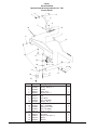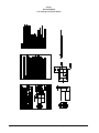
1
Operator's
Manual
ENCORE
S20/L20
U.S. Patent No. 5,383,251; No. 6,105,192; No. 6,557,207; & Patent Pending
READ THIS BOOK
This book has important information for the use and safe operation of this machine. Failure to read this
book prior to operating or attempting any service or maintenance procedure to your Clarke machine could
result in injury to you or to other personnel; damage to the machine or to other property could occur as
well. You must have training in the operation of this machine before using it. If operator(s) cannot read
English, have this manual explained fully before attempting to operate this machine.
Si Ud. o sus operadores no pueden leer el Inglés, se hagan explicar este manual completamente antes
de tratar el manejo o servicio de esta máquina.
All directions given in this book are as seen from the operator’s position at the rear of the machine.
For new books write to: Clarke®, 2100 Highway 265, Springdale, Arkansas 72764.
Form No. 70659A
12/06
Clarke®
Printed in the U.S.A.
Table of Contents
Operator Safety Instructions ............................................................................................................................ 3
Introduction & Machine Specifications ............................................................................................................. 5
Procedures for Transporting Machine ............................................................................................................. 6
Machine Control Panel ..................................................................................................................................... 8
Machine Controls and Features ...................................................................................................................... 9
How to Prepare the Machine for Operation ...................................................................................................... 10
How to Install the Batteries ................................................................................................................ 11
Battery Maintenance ........................................................................................................................... 11
How to Charge the Batteries ............................................................................................................. 12
How to Install or Remove a Brush or Pad Driver ............................................................................... 13
How to Operate the Machine ............................................................................................................................ 14
How to Operate the Squeegee .......................................................................................................... 14
Filling the Solution Tank .................................................................................................................... 14
Operating the Machine ....................................................................................................................... 15
Adjusting the Brush Pressure ........................................................................................................... 15
How to Clean a Dirty Floor ................................................................................................................. 16
SECTION II - Parts and Service Manual
How to Correct Problems in the Machine ........................................................................................................ 18
Maintenance ..................................................................................................................................................... 20
Procedures Before Work is Began .................................................................................................... 20
Procedures to Perform at the End of Work ........................................................................................ 21
Procedures to Perform Every Week ................................................................................................... 22
Maintenance for the Squeegee .......................................................................................................... 23
How to Adjust the Squeegee ............................................................................................................. 23
How to Clean the Solution Line ......................................................................................................... 24
Machine Variables and Accessories ............................................................................................................... 25
Accessories ...................................................................................................................................................... 27
Encore L20/S20 Final Assembly Drawing ....................................................................................................... 28
Parts List ............................................................................................................................................ 29
Encore L20/S20 Recovery Drawing ................................................................................................................. 30
Parts List ............................................................................................................................................ 31
Solution Tank Assembly Drawing .................................................................................................................... 32
Parts List ............................................................................................................................................ 33
Squeegee Lift Assembly Drawing and Parts List ............................................................................................ 34
Squeegee Assembly Drawing and Parts List ................................................................................................. 35
Squeegee Assembly Drawing and Parts List ................................................................................................. 36
Encore L20 Frame Transaxle Assembly Drawing and Parts List ................................................................... 37
Encore S20 Frame Assembly Drawing and Parts List .................................................................................... 38
Brush Lift Assembly Drawing and Parts List ................................................................................................... 39
Brush Housing Assembly Drawing and Parts List .......................................................................................... 40
Transaxle Repair Parts .................................................................................................................................... 41
Transaxle Drawing and Parts List ................................................................................................................... 42
Brush Motor Assembly Drawing and Parts List ............................................................................................... 43
Gearbox Assembly Drawing and Parts List ..................................................................................................... 44
Vacuum Motor Drawing and Parts List ............................................................................................................ 45
Battery Charger (40512A & 40513A) Drawing and Parts List ......................................................................... 46
Battery Charger (40512B & 40506B) Drawing and Parts List ......................................................................... 47
Optional Brake Assembly Drawing and Parts List .......................................................................................... 48
Kits:
Electronic Solution Valve Kit without Solution Shut-Off Drawing & Parts List ................................... 49
Electronic Solution Valve Kit with Solution Shut-Off Drawing & Parts List ........................................ 50
ESP Recycle System Kit .................................................................................................................... 51
Powerwand System Drawing & Parts List ........................................................................................ 52
Brush Meter Kit Parts List .................................................................................................................. 53
Hour Meter Kit Parts List .................................................................................................................... 53
Low Voltage Cut-Off Kit ...................................................................................................................... 54
For Machines with a 41150B Traverse Controller:
Rear Panel Assembly Drawing ........................................................................................................................ 56
Parts List ............................................................................................................................................ 57
Electrical Cover Assembly Drawing and Parts List ......................................................................................... 58
Encore L20 Electrical Schematic ..................................................................................................................... 59
Encore L20 Connection Diagram .................................................................................................................... 60
Encore S20 Electrical Schematic ..................................................................................................................... 61
Encore S20 Connection Diagram .................................................................................................................... 62
For Machines with a 41150C Traverse Controller:
Rear Panel Assembly Drawing ........................................................................................................................ 64
Parts List ............................................................................................................................................ 65
Electrical Cover Assembly Drawing and Parts List ......................................................................................... 66
Encore L20 Electrical Schematic ..................................................................................................................... 67
Encore L20 Connection Diagram .................................................................................................................... 68
Page
-2-
Clarke® Operator's Manual -Encore S20/L20
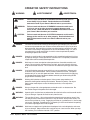
OPERATOR SAFETY INSTRUCTIONS
WARNING
AVERTISSEMENT
ADVERTENCIA
DANGER:
Failure to read and observe all DANGER statements could result in
severe bodily injury or death. Read and observe all DANGER
statements found in your Owner's Manual and on your machine.
WARNING:
Failure to read and observe all WARNING statements could result
in injury to you or to other personnel; property damage could
occur as well. Read and observe all WARNING statements found in
your Owner's Manual and on your machine.
CAUTION:
Failure to read and observe all CAUTION statements could result in
damage to the machine or to other property. Read and observe all
CAUTION statements found in our Owner's Manual and on your
machine.
DANGER:
Failure to read the Owner's Manual prior to operating or attempting any service or
maintenance procedure to your Clarke machine could result in injury to you or to
other personnel; damage to the machine or to other property could occur as well.
You must have training in the operation of this machine before using it. If you or
your operator(s) cannot read English, have this manual explained fully before
attempting to operate this machine.
DANGER:
Operating a machine that is not completely or fully assembled could result in injury
or property damage. Do not operate this machine until it is completely assembled.
Inspect the machine carefully before operation.
DANGER:
Machines can cause an explosion when operated near flammable materials and
vapors. Do not use this machine with or near fuels, grain dust, solvents, thinners,
or other flammable materials. This machine is not suitable for picking up hazardous
dust.
DANGER:
Lead acid batteries generate gases which can cause an explosion. Keep sparks
and flames away from batteries. Do not smoke around the machine. Charge the
batteries only in an area with good ventilation. Make sure that the AC charger plug
is unplugged from the wall receptacle before connecting or disconnecting the DC
plug to or from the battery pack.
DANGER:
Working with batteries can be dangerous! Always wear eye protection and
protective clothing when working near batteries. Remove all jewelry. Do not put
tools or other metal objects across the battery terminals, or the tops of the
batteries.
DANGER:
Using a charger with a damaged power cord could result in an electrocution. Do
not use the charger if the power cord is damaged.
WARNING:
Operating this machine from anywhere other than the back of the machine could result in
injury or damage. Operate this machine only from the rear.
WARNING:
This machine is heavy. Get assistance before attempting to transport or move it. Use
two able persons to move the machine on a ramp or incline. Always move slowly. Do
not turn the machine on a ramp. If operating machine on a gradient over 2%, do not stop,
turn or park. Read the "Procedures For Transporting" in this manual before transporting
as machine might topple over if not strapped.
WARNING:
Machines can topple over if guided over the edges of stairs or loading docks and cause
injury or damage. Stop and leave this machine only on a level surface. When you stop
the machine, put all switches into their "OFF" position.
Clarke® Operator's Manual - Encore S20/L20
Page -3-
Page
WARNING:
Maintenance and repairs performed by unauthorized personnel could result in damage or
injury. Maintenance and repairs must be performed by authorized Clarke personnel
only.
WARNING:
Any alterations or modifications of this machine could result in damage to the machine or
injury to the operator or other bystanders. Alterations or modifications not authorized by
the manufacturer voids any and all warranties and liabilities.
WARNING:
Electrical components of this machine can "short-out" if exposed to water or moisture.
Keep the electrical components of the machine dry. Wipe the machine down after each
use. For storage, keep the machine in a dry building.
WARNING:
Operating a machine without observing all labels and instructional information could result
in injury or damage. Read all machine labels before attempting to operate. Make sure all
of the labels and instructional information are attached or fastened to the machine. Get
replacement labels and decals from your Clarke distributor.
WARNING:
Wet floor surfaces can be slippery. Water solutions or cleaning materials used with this
type of machine can leave wet areas on the floor surface. These areas can cause a
dangerous condition for the operator or other persons. Always put "Caution" signs
around/near the area you are cleaning.
WARNING:
Improper discharge of waste water may damage the environment and be illegal.
The United States Environmental Protection Agency has established certain regulations
regarding discharge of waste water. Also, city and state regulations regarding this
discharge my be in effect in your area. Understand and follow the regulations in your
area. Be aware of the environment hazards of chemicals that you dispose.
CAUTION:
Use of this machine to move other objects or to climb on could result in injury or damage.
Do not use this machine as a step or furniture. Do not ride on this machine.
CAUTION:
Your machine warranty will be voided if anything other than genuine Clarke parts are
used on your machine. Always use Clarke parts for replacement.
-4-
Clarke® Operator's Manual -Encore S20/L20
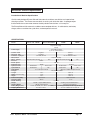
Introduction & Machine Specifications
Introduction & Machine Specifications
Clarke’s newly designed Encore S20 and L20 automatic scrubbers are efficient and superior floor
cleaning machines. The Encore uses one brush to scrub a path 20 inches wide. A squeegee wipes
the floor while the vacuum motor removes the dirty solution from the floor - all in one pass.
The Encore S20 and L20 automatic scrubbers come complete with two - 12 volt batteries, one battery
charger, either a scrub brush or a pad driver, and one operator’s manual.
SPECIFICATIONS:
Model
Motor, Vac
Power Supply
Solution Tank
Recovery Tank
Parabolic Squeegee
Motor, Brush
Motor Traction
Brushes
Brush Speed
Brush Pressure
Speed, Forward
Speed Reverse
Drive Wheels
Charger
Length
Width (over brush housing)
Height
Sound Level (DBA)
Cleaning Swath
Grade Cleaning
Weight
Shipping Weight
Battery Weight (each)
Shipping Dimensions
Encore L20 w/brake
Encore S20 w/brake
Encore S20 00890A
00880E
00890E
¾ HP three stage
tangential discharge
21 Amp
24 volt direct current
(2) 12 Volt 195AH Batteries
14 gallons
53 Liters
14 gallons
53 Liters
32" Hard, 34" Flex
81 cm Hard, 86 cm Flex
.75 hp PM 33 amp
.5 hp PM (.37kw) 23 Amp
N/A
.5 hp PM (.37kw) 23 Amp
NA
20 inch
51 cm
200 rpm
100 lbs.
45.36 kg
0=250 ft/min.
brush assist.
0=76.2 m/min.
brush assist
0=190 ft/min.
N/A
0=58 m/min.
NA
8" x 2" Neoprene thread
20.32 cm s 5.08cm Neoprene thread
24V, 25A, 115V/60hz
52½"
133.4 cm
22¼"
56.5 cm
43½"
110.5 cm
74, at 5 feet
74,at 1.5 meters
20 inch
51 cm
5° Incline
468 lbs. w/(2) 871334A batteries
212.28 kg w(2) 871334A batteries
607 lbs. w/wet batteries
275.33 kg w/wet batteries
113 lbs. (871334A) and 81 lbs. (871335A)
51.26 kg (871334A) and 36.74 kg (871335A)
28" x 65.5" x 46.5"
71.12 cm x 166.37 cm x 118.11 cm
Encore L20 - 00880A
Clarke® Operator's Manual - Encore S20/L20
Page -5-
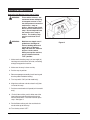
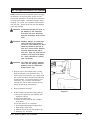
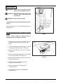
Procedures For Transporting
How to Put the Machine Into a Van or Truck
WARNING:
This machine is heavy. Get
assistance before attempting
to transport or move it. Use
two able persons to move the
machine on a ramp or
incline. Always move slowly.
Do not turn the machine on a
ramp. Do not stop and leave
the machine on a ramp or
incline. The loading ramp
must be a minimum of 32"
wide.
WARNING:
Machines can topple over if
guided over the edges of
stairs or loading docks and
cause injury or damage.
Stop and leave this machine
only on a level surface.
When you stop the machine,
put all switches into their
"OFF" position.
Figure #1
1. Make sure the loading ramp is at least eight (8)
feet long and a minimum of 32" wide, and strong
enough to support the machine.
2. Make sure the ramp is clean and dry.
3. Put the ramp in position.
4. Remove squeegee assembly, brush housing and
brush or pad driver before loading.
5. Turn key switch "ON" (on L20 model only).
6. Align the machine on a level surface five (5) feet
in front of the ramp.
7. Put the traverse knob at full speed (on L20 model
only).
8. For the L20 machine, push in either one of the
forward/reverse switches while pushing in the
white reverse switch. Back the machine up the
ramp. See figure 1.
9. For the S20 machine, push the machine backwards to the top of the ramp.
10. Turn the key switch "OFF".
Page
-6-
Clarke® Operator's Manual -Encore S20/L20
Procedures For Transporting (cont.)
11. Fasten the machine to the vehicle. Clarke
recommends a strap over the top of the
machine and a strap to keep the machine from
rolling forward or backwards. If this is not
done, there is a possiblity of the machine
toppling over.
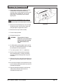
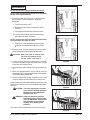
How to Remove the Machine From a Van or
Truck
1. Make sure there are no obstructions in the area.
2. Make sure the unloading ramp is at least eight
(8) feet long and a minimum of 32" wide, and
strong enough to support the machine.
Figure #2
3. Make sure the ramp is clean and dry.
4. Put the ramp in position.
5. Unfasten the machine.
WARNING:
The machine is heavy.
Make sure you use two able
persons to assist in moving
the machine down the
ramp.
6. On S20 model, get two people to pull machine
off ramp. It is recommended that the "S" model
be unloaded in the forward position.
7. Turn the key switch "ON". ("L" model only)
8. Set the traverse center knob to the slowest
forward speed setting. Carefully and slowly,
drive the machine to the top of the ramp and
start down.
9. While pushing in the right or left forward/reverse
switch the machine will go forward. See figure
2.
10. As the machine begins to travel down the ramp,
push in the forward/reverse switch to maintain a
slow downward speed.
11. Replace squeegee assembly, brush housing,
and brush or pad driver after machine is
unloaded and ready to use.
Clarke® Operator's Manual - Encore S20/L20
Page -7-
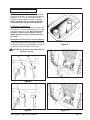
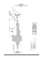
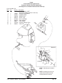
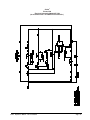
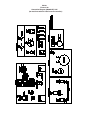
Machine Control Panel
Key Switch (See Figure 3, Item "A")
The key switch turns "ON" the power to the control
panel. "O" is "OFF" and "I" is "ON".
Forward Reverse Switch (See Figure 3, Item "B")
On Traverse Model Only
The forward/reverse switch turns the traverse motor
"on" forward and if the brush motor is in the down
position, activates the brush motor/solution control
module. There is a two second delay for the pad
motor to stop after releasing the switch. Either the
right or the left switch can be used. Use either switch
in conjunction with the white reverse switch to reverse
the traverse motor.
Reverse Switch (See Figure 3, Item "I")
On Traverse Model Only
The reverse switch, when used in conjunction with one
of the forward/reverse switches, causes the machine to
reverse directions. The reverse speed is 70% of the
forward speed. NOTE: Squeegee must be raised to
at least the first position.
Battery Meter (See Figure 3, Item "C")
The battery meter indicates the relative charge on the
battery pack. Do not continue to run the machine
when the needle is in the "red" area. This will shorten
the life of the battery pack.
Brush Pressure Meter (See Figure 3, Item "D")
The pad pressure meter indicates the relative amount
of pressure the pad is putting on the floor. To maximize run time on a battery charge, keep the needle
towards the center of the green area.
Hour Meter (See Figure 3, Item "E")
The hour meter indicates the number of hours the
machine has operated. It runs only when the brush
motor is on.
I
Circuit Breakers (See Figure 3, Items "F", "G" & "H")
The circuit breaker reset buttons are located on the
rear cover. The breakers are located as follows:
Item F - Traverse Motor (25 amp)
Item G - Vacuum Motor (30 amp)
Item H - Brush Motor (40 amp)
If a circuit breaker trips, determine which motor is not
operating and turn the key switch "OFF". Wait five
minutes and push the reset button back in. Turn the
key switch "ON" and try again. An authorized service
person should be contacted if the breaker trips again.
Control Handles (See Figure 3, Item "I")
The control handles are located at the rear of the
machine. They are used to guide the machine.
Solution Control Knob (See Figure 3, Item "J")
The solution control knob regulates the flow of chemical solution to the floor. To increase the flow, turn
knob clockwise. To decrease the flow, turn counter
clockwise.
Traverse Speed Knob (See Figure 3, Item "K")
To increase speed, turn knob clockwise.
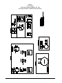
Vacuum Motor Switch (See Figure 4, Item "L")
To activate vacuum motor, lower squeegee handle.
Handle has two positions. Lowest position is operating position and the middle position is transport to
clear vacuum hose.
Brush Motor Switch (See Figure 4, Item "M")
To activate brush motor, lower handle. Brush Motor
and solution flow will activate when the traverse
buttons are pushed. To shut brush motor off, raise
handle to top position.
I
B
B
A
B
D
C
K
J
E
G
F GH
H
Figure 3
Page
-8-
Clarke® Operator's Manual -Encore S20/L20
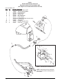
Machine Controls and Features
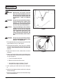
Squeegee Lift Handle, See Figures 5
The squeegee lift handle is located below the control
handles in the center. It is used to raise or lower the
squeegee. The vac motor is turned on when the
handle is lowered to either the first or last position.
NOTE: Squeegee must be raised to at least the
first position when the machine is backed up.
Float Shut Off, See Figure 6
The shut-off switch for the vac motor is located in the
recovery tank. It automatically turns off the vac motor
when the recovery tank is full. NOTE: If excessive
foaming in recovery tank, defoamer must be
added. Damage to vacuum motor could result
from foam.
Parking Brake, See Figures 7a and 7b (Optional)
The parking brake prevents movement of the machine.
It is located at the rear lower left side of the machine.
To engage the brake, push the pedal down (Figure 7a).
To release the brake, lift pedal up (Figure 7b).
Figure 6
CAUTION: Do not activate the brake while the
machine is moving.
L
M
Figure 7a
Figure 4
Figure 5
Clarke® Operator's Manual - Encore S20/L20
Figure 7b
Page -9-
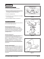
How To Prepare the Machine For Operation
How To Install The Batteries
The Encore machines uses two 12-volt batteries. The
batteries are located in the battery compartment under
the recovery tank.
To install the batteries, follow this procedure:
1. Turn machine off. Set brake (if equipped).
2. Make sure recovery tank is empty.
3. Open recovery tank and secure with latch.
4. Place the batteries in the tray as shown in
figure 8.
WARNING:
Lifting batteries without help
could result in an injury. Get
help to lift the batteries. The
batteries are heavy.
WARNING:
Working with batteries can
be dangerous. Always wear
eye protection and protective
clothing when working near
batteries. NO SMOKING!
(BATTERY NO. 40703A optional)
Figure 8
5. Connect the battery cables between batteries
and install long battery cable assembly as
indicated. See figure 8.
6. Join the connector from the battery pack to the
connector on the control panel. See figure 9.
7. Lower recovery tank.
NOTE:
Charge the batteries before using the
machine.
Battery Maintenance
The electrical power to operate the machine comes
from the storage batteries. Storage batteries need
preventative maintenance.
WARNING:
Figure 9
Working with batteries can
be dangerous. Always wear
eye protection and protective
clothing when working near
batteries. NO SMOKING!
Correct Fill Line
To maintain the batteries in good condition, follow
these instructions:
1. Keep the electrolyte at the correct level. The
correct level is between 1/4" below the bottom of
the tube in each cell and above the tops of the
plates. Check the level of the electrolyte each
time you charge the batteries. See figure 10.
Page
-10-
Figure 10
Clarke® Operator's Manual -Encore S20/L20
How To Prepare the Machine For Operation
NOTE: Check the level of electrolyte prior to charging
the batteries. Be sure the plates in each cell are
covered with electrolyte. Do not top off the cells prior
to charging the battery. Electrolyte expands during
charging. As a result, the electrolyte could overflow
from the cells. Always top off the cells with distilled
water after charging.
CAUTION: Irreversible damage will occur to
the batteries if the electrolyte
level does not cover the plates.
Keep the electrolyte at the correct
level.
CAUTION: Machine damage and discharge
across the tops of the batteries
can occur if the batteries are filled
above the bottom of the tube in
each cell. Do not fill the batteries
up to the bottom of the tube in
each cell. Wipe any acid from the
machine or the tops of the batteries. Never add acid to a battery
after installation.
CAUTION: Tap water may contain contaminants that will damage batteries.
Batteries must be refilled with
distilled water only.
2. Keep the tops of the batteries clean and dry.
Keep the terminals and connectors clean. To
clean the top of the batteries, use a damp cloth
with a weak solution of ammonia or bicarbonate
of soda solution. To clean the terminals and
connectors, use a terminal and connector
cleaning tool. Do not allow ammonia or bicarbonate of soda to get into batteries.
3.
Keep the batteries charged.
4.
To drain battery compartment: (See figure 11)
a. Always wear protective eye protection and
protective clothing.
b. Open brush motor cover.
c. Loosen the drain hose clip with a Phillips
screw driver.
d. Pull drain hose out to a container.
e. Place hand behind flange and open valve.
f. When empty, close valve.
g. Replace hose under clip and retighten clip.
h. Neutralize any acid spills.
Clarke® Operator's Manual - Encore S20/L20
Figure 11
Page -11-
How To Prepare the Machine For Operation
How To Charge The Batteries
WARNING: Charging the batteries in an area
without adequate ventilation
could result in an explosion. To
prevent an explosion, charge the
batteries only in an area with
good ventilation.
WARNING: Lead acid batteries generate
gases which could explode. Keep
sparks and flames away from
batteries. NO SMOKING!
Figure 12
WARNING: Failure to disconnect the AC plug
from the wall receptacle before
connecting or disconnecting the
DC connector on the charger
could result in an explosion.
Always disconnect the AC plug
from the wall receptacle before
connecting or disconnecting the
DC connector on the charger.
To charge the batteries, follow this procedure:
1. Put the charger on a flat surface. Make sure the
vents on the sides are at least two inches away
from walls and other objects. Make sure there
are no objects near the vents on the bottom of
the charger.
2. Set the parking brake (if provided) by putting it
into the down position. See figure 12. Make
sure the key switch is in "OFF" position.
Figure 13
3. Disconnect the battery pack connector from the
control housing connector. See figure 13.
4. Raise recovery tank and latch in place.
5. Connect the DC connector on the charger to the
battery pack connector. See figure 14.
6. Connect the charger to a properly grounded
single phase (3-wire) wall receptacle having the
voltage, frequency, and ampere capacity specified on the nameplate of the charger.
For more information on the use of the charger, read
the instruction book supplied with the charger.
Figure 14
Page
-12-
Clarke® Operator's Manual -Encore S20/L20
How To Prepare the Machine For Operation
How To Install The Brush Or Pad Driver
To install the brush or pad driver on the machine,
follow this procedure:
1. Turn the key switch "OFF".
2. Put the brush switch in the "UP" position.
3. Go to the front of the machine.
4. Open the brush motor cover and remove the
brush housing. See figures 15a and 15b.
5. Put a brush or pad driver under the brush housing. See figure 15c.
Figure 15a
6. Align the lugs on the motor with the slots in the
brush gimbal.
7. Pull the brush up and rotate counter clockwise
until gimbal locks.
8. Replace brush housing and close brush motor
cover.
How To Remove The Brush or Pad Driver
To remove the brush or pad driver from the machine,
follow this procedure:
1. Put the brush switch in the "UP" position.
Figure 15b
2. Turn the key switch "OFF".
3. Go to the front of the machine.
4. Open the brush motor cover and remove brush
housing. See figures 15a-15c.
5. Rotate brush clockwise with a quick snapping
action until brush releases.
6. Replace brush housing and close brush motor
cover.
Figure 15c
Clarke® Operator's Manual - Encore S20/L20
Page -13-
How To Operate The Machine
How To Operate The Squeegee
The squeegee wipes the floor while the vacuum motor
removes the dirty solution form the floor. Use your
right hand to lower or raise the squeegee handle. To
operate the squeegee, follow this procedure:
1. To lower the squeegee and start the vac motor,
move the squeegee lever to the right and down.
See figure 16.
2. To raise the squeegee, lift the squeegee lever up.
See figure 17.
Figure 16
NOTE: The center position lets the vac motor continue
to run with the squeegee off the floor to avoid drips and
also allows you to back up the machine.
How To Fill The Solution Tank
The solution tank lid is at the front. To fill the solution
tank follow this procedure:
1. Raise the solution tank lid.
2. Add a cleaning chemical to the solution tank.
For the correct amount of chemical, follow the
directions shown on the container.
3. Fill the solution tank with water.
Figure 17
4. Lower the solution tank lid.
WARNING: Water solutions or cleaning
materials used with this type of
machine can leave wet areas on
the floor surface. These areas can
cause a dangerous condition for
the operator or other persons.
Always put CAUTION signs near
the area you are cleaning.
WARNING: Machines can ignite flammable
materials and vapors. Do not use
with or near flammables such as
gasoline, grain dust, solvents and
thinners. Only use a cleaning
concentrate recommended by the
chemical manufacturer.
Page
-14-
Clarke® Operator's Manual -Encore S20/L20
How To Operate The Machine
A
B
Operating The Machine
NOTE: Put the machine in the lowest traverse speed
setting. Use the machine in an area that has no
furniture and objects until you can do the following:
C
A
D
1. Move the machine in a straight direction, forward
and backward.
2. Stop the machine safely.
3. Turn the machine both left and right and return to a
straight direction.
To move the machine, follow this procedure:
1. Release the parking brake (if equipped with
machine).
Figure 18
2. Turn the key switch to the "ON" position
3. Raise the brush to the highest setting.
4. Raise the squeegee.
5. Hold the control handle as shown in figure 18.
6. When either the right or left forward/reverse
switches (figure 18, item A) are pushed in, the
machine will go forward.
7. Control the speed of traverse by using the speed
control knob. (Figure 18, Item D)
8. To stop, release the forward/reverse switch.
9. To reverse the machine, push in the white reverse
switch (figure 18 item B) and either the right or left
forward/reverse switch (figure 18 item A) at the
same time. NOTE: Anytime the machine is reversed,
Figure 19
the squeegee must be raised to either of the two up
positions. This will prevent damage to the squeegee.
10. To stop, release the forward/reverse switch.
11. To turn the machine, push the rear of the machine
to the side.
12. When you stop the machine, turn the key switch
"OFF" and set the parking brake (if equipped).
Adjusting The Brush Pressure
WARNING:
1.
Make sure the battery connector
covers are on before making adjustments. Don't let metal parts touch the
battery connections.
To increase or decrease the brush pressure for
"Heavy Scrub", raise the recovery tank to gain
access to the adjustment.
2. Turn the brush lift spring lock nut (figure 19) clockwise for more pressure and counterclockwise for
less pressure. Use the brush pressure meter (figure
18, Item C) to determine the best setting. The
needle should stay in the green area.
Clarke® Operator's Manual - Encore S20/L20
Page -15-
How To Operate The Machine (cont)
How To Clean A Floor
WARNING: Water solutions or cleaning materials
used with this type of machine can
leave wet areas on the floor surfaces.
These areas can cause a dangerous
condition for the operator or other
persons. Always put CAUTION signs
near the area you are cleaning.
To clean a floor follow this procedure:
1. Set the parking brake (if equipped with machine.)
2. Put the water and a cleaning chemical in the clean
solution tank.
3. Release the parking brake (if equipped with machine.)
4. Turn the key switch "ON".
5. Lower the squeegee.
6. Put the brush lever switch in the floating position or
heavy scrub position.
NOTE: Keep the machine moving when the brush is
rotating on the floor. Pre-wet brush/pad or keep light
pressure on brush until solution flow is adequate to keep
brush/pad from scratching floor.
7. Turn the solution knob to the right to activate the flow
of solution. Adjust the flow of clean solution to the
flow desired.
8. Move the machine across the floor in the forward
direction.
9. Make a 180° turn.
NOTE: When you make more passes across the floor, let
the brush clean approximately 2 inches of the area
already cleaned by the brush.
NOTE: During most cleaning procedures, apply and
remove the solution in one operation.
How To Clean A Very Dirty Floor
To clean a very dirty floor, follow this procedure:
1. Apply solution to the floor.
2. Do not lower the squeegee, which will keep the
vacuum motor off.
3. Lower the brush or pad and scrub the floor.
4. Scrub the floor again with additional solution and
lower the squeegee.
5. Pick up all the solution with the squeegee.
Page
-16-
Clarke® Operator's Manual -Encore S20/L20
ENCORE
S20/L20
Section II
Parts and Service Manual
(70659A)
U.S. Patent No. 5,383,251; No. 6,105,192; No. 6,557,207; & Patent Pending
Clarke® Operator's Manual - Encore S20/L20
Page -17-
HOW TO CORRECT PROBLEMS IN THE MACHINE
PROBLEM
There is no solution flow.
The solution flow does not stop.
The machine does not remove all the
water from the floor.
The batteries do not give the normal
running time.
Page
-18-
CAUSE
ACTION
The solution valve is closed.
Open the solution valve.
There is an obstruction in the solution hose
or filter.
Remove the obstruction from the hose and the
filter.
The solution valve or electric wiring is
damaged.
Repair or replace the valve and the electric
wiring.
The solution tank is empty.
Fill the solution tank.
The solution module is damaged.
Check solution module
The solution valve is open or dirty.
Close or Clean the solution valve.
The solution valve or wiring is damaged.
Repair or replace the valve and the wiring.
The solution valve is dirty
Clean the solution valve.
There is a damaged seat and washer in the
solution valve.
Replace the seat and washer.
The solution module is damaged.
Check solution module.
The squeegee is up
Lower the squeegee.
The squeegee tilt is not correct.
(See Figure 11, page 23)
The vacuum tank is full.
Drain the tank.
The screen filter is dirty.
Clean the screen filter.
There is an obstruction or damage in the
squeegee, squeegee hose or standpipe.
Remove the obstruction or repair the damage.
The vacuum motor is not running.
Check for tripped breaker. Have an authorized
service person make repairs.
The vacuum motor runs slow
See pg 49 for brush replacement intervals.
The squeegee hose is disconnected, or
damaged
Check and connect hose.
The squeegee blade is damaged, worn, or
incorrectly installed.
Turn or replace the squeegee blade.
Correctly install the squeegee blade.
The squeegee pressure is not correctly
adjusted.
Adjust the pressure of the squeegee.
The gaskets on the cover of the recovery
tank are damaged.
The recovery tank lid is on wrong.
Replace the gaskets.
The battery terminals are dirty or damaged.
Clean the terminals and connectors. Replace
the damaged cables. Charge the batteries.
The electrolyte level is too low.
Add distilled water to each cell and charge the
batteries.
The batteries are not fully charged.
Charge the batteries for a full 16 hour charge.
The charger is damaged.
Have an authorized service person repair the
charger.
The battery is defective.
Check voltage of each cell while discharging.
The batteries are disconnected.
Connect the batteries.
Brush is in heavy scrub setting.
Run in float position.
Rotate lid 180° and replace.
Clarke® Operator's Manual -Encore S20/L20
PROBLEM
The cleaning is not even.
CAUSE
ACTION
The scrub brush or pad is worn.
Replace the scrub brush or pad.
There is damage to the brush assembly,
caster or the solution valve.
Have an authorized service person make
the needed repairs.
The brush motor is not running
Check for tripped breaker. Reset. Check
for loose connections.
The solution level is low.
Fill the solution tank.
NOTE: If the problem continues consult an
authorized service person.
The machine does not run.
The machine loses power.
Reset the circuit breaker.
Key or switch is off.
Turn key or switch on.
Batteries are unplugged.
Battery terminals are dirty.
Check the battery connections.
Batteries are discharged
Check battery gauge and recharge
NOTE: If the problem continues consult an
authorized service person.
Clarke® Operator's Manual - Encore S20/L20
Page -19-
MAINTENANCE
WARNING: Maintenance and repairs must be
done by authorized personnel only.
WARNING: Always empty the solution tank and
recovery tank before doing any
maintenance.
WARNING: Keep all fasteners tight.
These Maintenance Procedures Must Be Done Every Day
Keep the machine clean, it will need fewer repairs and
have longer life.
Do These Procedures When You Begin Your Work
Period
Figure 1
NOTE: Always engage the parking brake (if
equipped) before servicing the machine.
1. Disconnect the plug on the charger from the
connector on the back of the machine. See
figure 1
A
2. Join the connector from the batteries (1) to the
control panel cable connection. See figure 1.
3. Make sure the recovery tank lid is on correctly.
See figure 2.
4. Make sure the Screen filter over the vacuum motor
is clean and in position. See figure 2 (a)
5. Make sure the valves on the drain hoses are clean.
Tightly close the valves.
Figure 2
6. Make sure brush housing and skirt are in
position on the brush head.
7. Make sure the brush is in position and
installed correctly
8. Check the installation of the squeegee and
squeegee hose.
Page
-20-
Clarke® Operator's Manual -Encore S20/L20
MAINTENANCE
Do These Procedures When You End Your Work
NOTE: Always engage the parking brake (if equipped)
before servicing the machine.
1. Drain the solution tank (Figure 3 ) and the recovery
tank (Figure 4). To drain the tanks , follow this
procedure:
a. Turn the key switch “OFF”.
b. Remove the drain hose from the back of the
machine.
c. Put the end of the hose over a drain or bucket.
Figure 3
d. Turn the valve handle to the left. Pull the handle
out to open the drain. (Figure 5)
NOTE: Have the opening in the side of the valve away
from you when you open the valve.
e. To open the valve completely, turn the handle
to the right. Pull the handle out of valve. (Figure
6)
2. Flush the tanks. To flush the tanks, put clean water in
the tank through the opening on top of the tank.
CAUTION: Make sure water or solution does
not enter the opening for the
vacuum motor. See figure 2.
3. If a tank or drain hose has an obstruction, use a high
pressure water hose to flush the tank or hose. Put the
water hose into the drain hose.
Figure 4
4. Leave the tanks and the drain valves open to dry in the
air.
5. Check the squeegee blade. Use a cloth to clean the
squeegee blade. If the squeegee blade is damaged or
worn, turn or replace the blade.
6. Check and clean the solution lid gasket. Use a mild
cleaning solution and rinse the parts in clean water.
Check the batteries and add distilled water as needed. The
correct level is within 1/4 inch of the bottom of the tube in
each cell.
Figure 5
CAUTION: Tap water may contain contaminants that will damage batteries.
Batteries must be refilled with
distilled water only.
WARNING: Lead acid batteries generate
gases which can cause an explosion. NO SMOKING. Always wear
eye protection and protective
clothing when working near
batteries.
Use a clean cloth and wipe the surface of the machine.
Figure 6
Clarke® Operator's Manual - Encore S20/L20
Page -21-
MAINTENANCE
These Maintenance Procedures Must Be Done Every
Week:
WARNING:
Maintenance and repairs must be
done by authorized personnel only.
Always empty the solution tank and
the recovery tank before doing any
maintenance. Keep all fasteners
tight.
WARNING:
Always wear eye protection and protective clothing when working near
batteries. Do not put tools or other
metal objects across the battery terminals or the tops of the batteries.
CAUTION:
To prevent damage to the machine,
and discharge across the tops of the
batteries, do not fill the batteries
above the bottom of the tube in each
cell. Wipe any acid from the machine or the tops of the batteries. Do
not add acid to battery after installation.
WARNING:
Figure 7
Always wear eye protection and protective clothing when working near
batteries. NO SMOKING!
1. To inspect batteries, tip up recovery tank and latch the
stop to hold the tank up. See Figure 7.
2. Disconnect the batteries. Use a cloth and a solution
of ammonia or bicarbonate of soda to wipe the top of the
batteries. Clean the battery terminals. Reconnect the
batteries.
3. Check the hoses for leaks, obstructions and other
damages.
Figure 8
4. Check and clean the filter screen in the solution hose.
To clean the screen, follow this procedure: (See figures
13 and 14 page 24)
a. Turn the connector to the left.
b. Remove and clean the filter screen.
c. Install the filter screen in the hose. Turn the
connector to the right to connect the hose.
5. Use a grease gun to lubricate the caster. See figure
8.
6. Check the squeegee and the scrub brush or the pad
driver for damage.
7. Check the squeegee and the vacuum hose for damage,
leaks and obstructions.
Page
-22-
Clarke® Operator's Manual -Encore S20/L20
MAINTENANCE
Maintenance For The Squeegee
To remove the squeegee, follow this procedure:
1. Remove the squeegee assembly by loosening the two
knobs that attach the squeegee to the machine. Pull
the squeegee assembly off. See figure 9.
2. Inspect the squeegee blade.
3. If the blade is worn, turn the blade so that a new edge
is in the wiping position.
Figure 9
4. Reinstall squeegee assembly on the machine.
How To Adjust The Squeegee
The following adjustments are set at the factory, however
they may require slight adjustment.
Adjusting Squeegee Pressure:
To adjust the pressure, refer to Figure 10. Proper
adjustment will produce a uniform flare along the rear
blade when the machine is moved forward. To increase
pressure, loosen bolt and slide squeegee mount down.
To decrease the pressure, loosen the bolt and slide
squeegee mount up.
Adjusting Squeegee Tilt:
The tilt of the squeegee causes the rear blade to raise up
in the center or on the ends, depending on which
direction the tilt is changed. For tilt adjustment, refer to
figure 11. Loosen left and right screw "X". In order to
bring the rear blade down in the center, tip "Y" down. To
bring both ends down, tip "Y" up. Make very small
adjustments and try it until a uniform flare is achieved.
Changing the tilt may also require readjusting the squeegee pressure.
Adjusting Squeegee Swing:
The factory sets the squeegee swing for using the 33"
squeegee. If you are using the optional 29" squeegee, the
stop screws (page 35, ref. # 20) must be adjusted in. This
is done by loosening the jam nut (page 35, ref. #10); turning
the screw in; and then retightening the nut. The squeegee
(29" or 33") is properly adjusted when it will swing all the
way left or right to within 3/4" of the drive wheels without
hitting them.
Clarke® Operator's Manual - Encore S20/L20
Figure 10
X
Y
Figure 11
Page -23-
MAINTENANCE
Adjusting Squeegee Blades:
When properly installed the front blade should be approximately .12 above the rear blade. See figure 12.
WARNING: Maintenance and repairs
must be done by authorized
personnel only .
0.12" (3,0 mm)
WARNING: Electrical repairs must be
done by authorized
personnel only.
Figure 12
Consult your Clarke Authorized Service Person to do
the service procedures.
Use only genuine Clarke parts.
Page
-24-
Clarke® Operator's Manual -Encore S20/L20
Battery Traverse 115V
Battery-Traverse
- 230V
Battery Traverse
230V
Battery Traverse - 115V
Encore L20 9/02
Machine Variables and Accessories
00881A
Breakdown:
00880A
871334
51447D
40512A
Encore L20 Base Machine
Battery, 195 AH, Wet, 12 Volt (2)
20" Polypropylene Brush
24 VDC, 25 Amp, 115V/60 Hz Battery Charger
Breakdown:
00880A
871334
51453D
40512A
Encore L20 Base Machine
Battery, 195 AH, Wet, 12 Volt (2)
Pad Driver
24 VDC, 24 Amp, 115V/60 Hz Battery Charger
Breakdown:
00880A
871335
51447D
40513A
Encore L20 Base Machine
Battery, 195 AH, Dry, 12 Volt (2)
20" Polypropylene Brush
24 VDC, 25 Amp, 230V/50 Hz Battery Charger
Breakdown:
00880A
871335
51453D
40513A
Encore L20 Base Machine
Battery, 195 AH, Dry, 12 Volt (2)
Pad Driver
24 VDC, 25 Amp, 230V/50 Hz, Battery Charger
Breakdown:
00880A
871376
51447D
40520A
Encore L20 Base Machine
Battery, 95 AH, Wet, 12 Volt (2)
20" Polypropylene Brush
24 VDC, 8 Amp, 115/60 Hz Battery Charger
Breakdown:
00880A
871376
51453D
40520A
Encore L20 Base Machine
Battery, 95 AH, Wet, 12 Volt (2)
Pad Driver
24 VDC, 8 Amp, 115/60 Hz Battery Charger
Breakdown:
00880A
871377
51447D
40521A
Encore L20 Base Machine
Battery, 95 AH, Dry, 12 Volt (2)
20" Polypropylene Brush
24 VDC, 8 Amp, 230V/50 Hz Battery Charger
Breakdown:
00880A
871377
51453D
40521A
Encore L20 Base Machine
Battery, 95 AH, Dry, 12 Volt (2)
Pad Driver
24 VDC, 8 Amp, 230V/50 Hz Battery Charger
00882A
00883A
00884A
00885A
00886A
Battery 230
00887A
00888A
Clarke® Operator's Manual - Encore S20/L20
Page -25-
Encore S20 9/02
Machine Variables and Accessories
Battery 115V
00891A
Breakdown:
00890A
871334
51447D
40512A
Encore S20 Base Machine
Battery, 195 AH, Wet, 12 Volt (2)
20" Polypropylene Brush
24 VDC, 25 Amp, 115/60 Hz Battery Charger
Breakdown:
00890A
871334
51453D
40512A
Encore S20 Base Machine
Battery, 195 AH, Wet, 12 Volt (2)
Pad Driver
24 VDC, 25 Amp, 115/60 Hz Battery Charger
Breakdown:
00890A
871335
51447D
40513A
Encore S20 Base Machine
Battery, 195 AH, Dry, 12 Volt (2)
20" Polypropylene Brush
24 VDC, 25 Amp, 230V/50 Hz Battery Charger
Breakdown:
00890A
871335
51453D
40513A
Encore S20 Base Machine
Battery, 195 AH, Dry, 12 Volt (2)
Pad Driver
24 VDC, 25 Amp, 230V/50 Hz Battery Charger
Breakdown:
00890A
871376
51447D
40520A
Encore S20 Base Machine
Battery, 95 AH, Wet, 12 Volt (2)
20" Polypropylene Brush
24 VDC, 8 Amp, 115V/60 Hz Battery Charger
Breakdown:
00890A
871376
51453D
40520A
Encore S20 Base Machine
Battery, 95 AH, Wet, 12 Volt (2)
Pad Driver
24 VDC, 8 Amp, 115V/60 Hz Battery Charger
Breakdown:
00890A
871377
51447D
40521A
Encore S20 Base Machine
Battery, 95 AH, Dry, 12 Volt (2)
20" Polypropylene Brush
24 VDC, 8 Amp, 230V/50 Hz Battery Charger
Breakdown:
00890A
871377
51453D
40521A
Encore S20 Base Machine
Battery, 95 AH, Dry, 12 Volt (2)
Pad Driver
24 VDC, 8 Amp, 230V/50 Hz, Battery Charger
00892A
Battery 115V
Battery
Battery Traverse
- 230V230V
00893A
00894A
00895A
00896A
Battery 230V
00897A
Page
00898A
-26-
Clarke® Operator's Manual -Encore S20/L20
Accessories
ACCESSORIES
Description
Pad Driver, Dual Direction
Base
Retainer
Pad/Brush Clutch Plate Metal
Spacer (for Clutch Plate 66649A)
Dual Direction Clutch Plate
Spacer (for Clutch Plate 30034A)
Clutch Plate Screws
Clutch Plate Nuts
Grit Brush Dual Direction
Poly Brush Dual Direction
Clean Grit Dual Direction
Nylon Brush .016 Dual Direction
Kit, Conversion from metal to Dual Direction Clutch Plate
Power Wand Kit
ESP Recycle System Kit
Clarke Care Kit
Hour Meter Kit
29" Squeegee Kit
32" Squeegee Kit
Polydur, Protectant
Kit, Grease Gun
Kit, Low Voltage Cut-off 24 Volt
Brush Meter Option
Electronic Solution Module
Brake Option
Part No.
51453D
57370A
57369A
66649A
58531A
30034A
58530A
962819
80084A
51450D
51447D
51474D
51482D
10055A
10662A
10663A
14607A
10656A
18820L
10129L
50478A
55420A
14097A
10667A
10669A
10635A
Pads by Case
Color
Yellow
White
Red
Green
Blue
Brown
Black
Ultra H.S.
Clarke® Operator's Manual - Encore S20/L20
2000
979199
976067
976068
976169
976069
976070
976170
979206
Page -27-
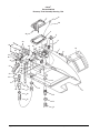
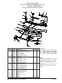
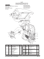
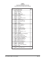
Clarke®
Encore S20 / L20
Final Assembly Drawing 8/04
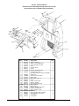
1
25
23
26
2
22
23
20
21
29
4
19
27
18
3
5 6
7
17
8
16
15
9
13
30
12
11
5
6
7
28
10
6
7*
* Recommended 12 ft. lbs torque, also apply blue loctite.
Page
-28-
Clarke® Operator's Manual -Encore S20/L20
Clarke®
Encore S20 / L20
Final Assembly Parts List 3/06
Ref #
1
2
3
4
5
6
7
8
9
10
11
12
13
15
16
17
18
19
20
21
22
23
25
26
27
28
29
30
NI
NI
NI
NI
NI
Part No.
Page 30
Page 32
Pg 58, 66
Pg 56, 64
980651
980652
85811A
Page 34
Pg 35, 36
980210
980679
20308A
85727A
Page 37
Page 38
980638
Page 39
44809B
41601A
41602A
Page 40
32403B
36902A
80256A
80255A
699292
85518A
47202A
915102
Page 27
41211A
41206A
38720A
38721A
Description
Tank Asm., Recovery
Tank Asm., Solution
Cover Asm., Electrical
Panel Asm., Rear
Washer, Flat, 5/16
Washer, Lock, 5/16
Screw, 5/16-18 x 3/4
Lift Asm., Squeegee
Squeegee Asm.
Washer, Impeller
Washer, Spacer, 3/16 x 1½ x 1/8
Adaptor, Motor
Screw, 3/8-16 x 1.0
Transaxle Asm.
Axle Asm.
Washer, Lock, 3/8
Lift Asm., Brush
Motor, Brush
Connector
Housing, Connector
Housing Asm., Brush
Cover, Front
Pins, Nylon
Rivet, Plastic Anchor
Washer, Nylon
Wire Tie
Screw
Suppressor
Key, Shaft
Brush or Pad Drivers
Cable Asm., Battery
Cable Series
Spacer, Battery Front
Spacer, Battery Side
Qty.
L20
Ref.
Ref.
Ref.
Ref.
8
9
9
Ref.
Ref.
1
1
1
4
Ref.
4
Ref.
1
2
2
Ref.
1
2
1
1
2
6
1
1
1
1
1
1
1
Qty.
S20
Ref.
Ref.
Ref.
Ref.
8
9
9
Ref.
Ref.
1
1
1
4
Ref.
4
Ref.
1
2
2
Ref.
1
2
1
1
2
6
1
1
1
1
1
1
1
NOTE: For battery placement and connections see page 10.
Clarke® Operator's Manual - Encore S20/L20
Page -29-
Clarke®
Encore S20/L20
Recovery Tank Assembly Drawing 7/02
2
1
40
3
38
5
4
6
33
32
34
37
36
33
41
42
30
35
39
10
7
8
42
9
31
25
24
29
28
25 26
23
27
22
4
21
19
20
18
17
16
13
11
12
15
13
14
Page
-30-
Clarke® Operator's Manual -Encore S20/L20
Clarke®
Encore S20/L20
Recovery Tank Assembly Parts List 7/02
Drawing #18114A
Ref #
1
2
3
4
5
6
7
8
9
10
11
12
13
14
15
16
17
18
19
20
21
22
23
24
25
26
27
28
29
30
31
32
33
34
35
36
37
38
39
40
41
42
NI
Part No.
36209A
962798
34256A
837304
58069A
39336B
59877A
56459A
10660A
32401B
30251A
30132A
752020
824103
30443A
832002
839401
65503A
833407
833901
962943
52206A
962987
674110
41809A
43402A
920797
872010
43401A
962986
87621A
85728A
87026A
44917A
643418
58533A
82100A
81110A
85519A
692409
47202A
699202
839410
Clarke® Operator's Manual - Encore S20/L20
Description
Lid
Screw, 10-24 x ½ Pan
Gasket, Lid
O-Ring
Strainer
Tube, Stand
Seal, Washer
Relief, Strain
Switch, Float Kit (includes #'s 7,25,26)
Lid, Fill, Solution
Tank, Recovery
Tube, Stand
Clamp, Hose
Hose, Squeegee
Hose, Drain
Clamp
Valve, Drain
Latch, Recovery
Gasket, Drain
Drain Valve Handle
Screw, 8-18 x ½ PN
Chain
Screw, 10-24 x 3/8 Pan
Hose
Contact
Housing, Connector
Nut
Clamp, Hose
Housing, Vac Motor Connector
Screw, 5/16-18 x 3/4
Washer, Shoulder Nylon
Screw, ¼-20 x 4 Hex
Washer, Flat, ¼
Motor, Vac
Gasket
Spacer
Nut, Lock
Nut, 10-24 ESNA
Screw
Chain, Cover
Suppressor
Wire Tie
Valve Asm.
(includes Item#17,19, 20, 21, 22)
Qty.
1
1
1
2
1
1
1
1
1
1
1
1
2
1
1
1
1
1
1
1
1
1
1
1
4
2
1
1
2
1
1
3
3
1
1
3
1
1
1
1
1
2
1
Page -31-
Clarke® Encore S20/L20
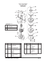
Solution Tank Assembly Drawing 8/04
7
8
6
5
4
9
3
2
1
10
11
12
24
23
14
21
14
25 26
24
23
14
21
13
22
15
L20 only
16
17
42
42
33
14
41
S20 only
27
39
29
28
30
31
37
36
35
33
34
31
32
Page
-32-
Clarke® Operator's Manual -Encore S20/L20
Clarke®
Encore S20/L20
Solution Tank Assembly Parts List 8/04
Ref #
1
2
3
4
5
6
7
8
9
10
11
12
13
14
15
16
17
21
22
23
24
25
26
27
28
29
30
31
32
33
34
35
36
37
38
39
41
42
NI
Part No.
752020
30442A
832002
839401
833407
833901
962987
52206A
962943
30250A
64517A
85398A
55162A
50248A
39335A
59612A
59610A
30172A
51204A
52414A
51518A
84237A
782002
85702A
832102
962798
820823
53618A
39337A
51526A
81110A
81104A
849401
678215
53619A
11703A
35138A
53562A
839410
NI
39332A
NI
NI
NI
50389A
50390A
50391A
Description
Clamp
Hose, Drain
Clamp
Valve, Drain
Gasket, Drain
Drain Valve Handle
Screw, 10-24 x 3/8
Chain
Screw, 8-18 x ½ PN
Tank, Solution
Hinge, Solution/Recovery
Screw, ¼-20 x 5/8
Hosebarb
Clamp, Hose
Hose, 17’
Valve, Drain, Battery
Valve, Flow, Electric
Hose, Braided, .375 ID x 16½”
Valve, Solution
Connector Straight Hose/Tank
Bushing
Screw, 10-32 x ½
Clamp
Screw, ¼-20 x 13/4
Clamp
Screw 10-24-½
Bracket
3/8 x 3/8 NPT Hosebarb
Hose 2½"
Hosebarb, Elbow
Nut, 10-24
Nut, ¼-20 ESNA
Valve
Spacer
3/8 x ¼ NPT Hosebarb
Solution Cable
Hose, Solution
Filter, Bowl
Valve Asm.
(includes Item #4, 5, 6, 8, 9)
Bulk 100 ft. of hose per P/N
39335A and 39337A
Plunger
Spring
Diaphragm
53562A Components
Clarke P/N
Description
50081A
Bowl, Filter
53563A
Filter, Screen
53564A
Upper Body
54369A
Gasket, Bowl
Clarke® Operator's Manual - Encore S20/L20
L20
1
1
1
1
1
1
1
1
1
1
1
4
1
6
1
1
1
1
1
2
2
1
1
1
1
1
-
S20
1
1
1
1
1
1
1
1
1
1
1
4
1
6
1
1
1
1
2
2
1
1
1
1
2
1
2
1
1
2
1
1
1
ref.
1
1
-
-
-
Qty.
1
1
1
1
Page -33-
Clarke® Encore S20/L20
Squeegee Lift Assembly Drawing and Parts List 10/03
Drawing # 18814A
1
19
2
3
4
6
5
ref.
19
7
18
8
17
6
10
10
20
11
12
6
13
13
6
9
22
21
14
4
16
Ref #
1
2
3
4
5
6
7
8
9
10
11
12
13
14
16
17
18
19
20
21
22
Page
-34-
Part No.
ref.21,pg56, 65
30517A
85600A
87026A
50034A
81104A
85396A
60225A
170915
920208
962481
85730A
87031A
69860B
34260B
61263A
25201A
61677A
86408A
980638
81111A
Description
Handle
Bushing
Screw, ¼-20 x 3/4
Washer, ¼, SS
Spring, Squeegee
Nut, Nylock, ¼
Screw, ¼-20 x 2 SS
Swivel, Squeegee
Screw, ¼-20 x 3/4
Nut, ¼-20, Plated
Screw, ¼-20 x 1¼ Hex
Screw, 3/8-16, Hex
Washer, Flat, 3/8, SS
Pin, Bracket Weldment
Gasket, Squeegee
Bracket, Tube
Knob, Clamping
Cable, Lift, Squeegee
Screw, ¼-20x1 Truss
Lockwasher, 3/8 LT Spring Type
Nut, 3/8-16 ESNA
Qty.
1
1
3
1
6
1
1
4
4
2
1
3
1
Ref.
1
Ref.
2
1
1
Clarke® Operator's Manual -Encore S20/L20
Clarke® Encore S20/L20
Squeegee Assembly Drawing and Parts List 12/06
29" Asm. - 18820A (Optional)
33" Asm. - 18821A (discontiued, use 10129A)
20
1
1
18
17
21
2
3
19
2
4
4
5
6
16
7
10
11
15
14
8
9
13
12
Ref #
1
2
3
4
5
5
6
7
8
9
10
11
12
13
14
15
16
17
18
19
20
21
Part No.
962522
980687
59950A
81111A
30950A
30763L1
38713A
38719A
30931L
30946A
62421A
86004A
62712A
37016A
80011A
55722A
62441A
62445A
170932
69059A
69672A
81207A
419702
81301A
25201A
34260B
Description
Screw, 3/8-16 x 2" Hex
Washer, 15/32 I.D. x 15/16 O.D.
Wheel, Guide
Nut, 3/8-16 ESNA
Blade, Front, Linatex
Blade, Ribbed, Urethane
Spacer, 29"
Spacer, 33"
Blade, Outer, Linatex
Blade, Outer, Rubber
Clamp, End
Screw, ¼-20 x 1½ Hex
Duct, Squeegee Inlet
Pad, Squeegee Grip
Screw, 3/8-16 x 3 CR S.S.
Latch, Squeegee Strap
Clamp, Squeegee 29"
Clamp, Squeegee 33"
Rivet, Pop 3.16 S.S. 1/8"
Squeegee Weldment 29"
Squeegee Weldment 33"
Nut, 3/8-16 S.S.
Wheel
Nut, 3/8-16 Jam S. S.
Knob
Gasket
Clarke® Operator's Manual - Encore S20/L20
29"
4
6
2
4
1
2
1
1
1
1
1
2
1
1
2
1
2
2
2
Ref
Ref
33"
4
6
2
4
1
2
1
1
1
1
1
2
1
1
2
1
2
2
2
Ref
Ref
Optional:
NI 30938A
NI 30949A
NI 30930A
NI 30947A
Nitrile 29" Outer Blade
Nitrile 33" Outer Blade
Rubber 29" Inner Blade
Rubber 33" Inner Blade
NOTE:
When changing blades loosen nuts #19.
Clamp blades on squeegee. Retighten
#19 nuts. This will allow spacer #6 to
readjust to different blade thickness.
NOTE: indicates a change has been
made since the last publication of this
manual.
Page -35-
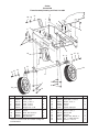
Clarke®
Encore S20/L20
Squeegee Assembly Drawing 12/06
Drawing # 10068A and 10129A (used on machines built after 4-8-03, starting with Serial #AC2077)
1
19
2
6
21
3
4
18
5
20
21
17
7
8
9
10
11
12
39"
Qty
1
80252A
80253A
980657
60243A
30049B
81104A
60254A
50958A
30048A
60272A
60234A
50835A
930086
60252A
60232A
30069L
30067L
30058A
30047A
30717L1
30764L1
80011A
81301A
34260B
25201A
60358A
61370A
80280A
Screw, ¼-20 x 1 Hex SS
Screw, ¼-20 x 1½ Hex SS
Washer, ¼ Lock
Bracket, Squeegee Wheel
Wheel, Squeegee
Nut, ¼-20
Bolt, Shoulder 5/16x 2¼
Ring, 3/8 ID Snap
Wheel, Guide, 4 Inch Diameter
Channel, Squeegee Weldment 39”
Channel, Squeegee Weldment 32”
Latch, Squeegee Clamp
Rivet, 3/16 x .450 Aluminum
Strap, Clamp, Squeegee Retainer 39”
Strap, Clamp, Squeegee Retainer 32
Blade, Rear, Linatex, 39”
Blade, Rear, Linatex, 32”
Spacer, Squeegee 39”
Spacer, Squeegee 32
Blade, Front, Linatex 39”
Blade, Front, Linatex 32”
Screw, 3/8-16 x 3
Nut, 3/8-16 Jam SS
Gasket
Knob
Shim, Squeegee Wheel
Weight
Nut, Squeegee Backup
15
15
16
17
18
19
20
21
22
4
4
2
4
2
2
2
2
1
1
2
1
1
1
1
2
2
1
2
2
8
2
10
12
9L
15
Description
13
13
14
-36-
16
Part No.
10
11
12
Page
14
Ref. #
2
3
4
5
6
7
8
9
NOTE: indicates a
change has been
made since the last
publication of this
manual.
22
10
06
8L
13
32"
Qty
4
4
2
4
2
2
2
2
1
1
2
1
1
1
1
2
2
1
2
2
4
2
Clarke® Operator's Manual -Encore S20/L20
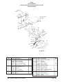
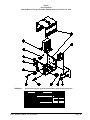
Clarke® Encore L20
Frame Transaxle Assembly Drawing and Parts List 8/04
21
20 22
1
4
2
5
5
6
4
8
7
27
19
24 18
7
Starting with serial #AC0068
23
14 15
8
29
28
29
9
26
16 25
9
17
32
4
16 15 14
26 25
10
33
31
30
11
12
12
7
13
7
13
10
Ref #
1
2
4
5
6
7
8
9
10
11*
12
13
14
15
16
Part No.
63431A
87607A
85811A
85727A
85836A
87031A
920110
915044
69204B
69204A
10380A
62435A
81105A
962620
980652
980205
Description
Frame
Washer, Nylon
Screw, 5/16-18 x 3/4
Screw, 3/8-16 x 1
Screw, 3/8-16 x 2
Washer, Flat, 3/8, SS
Nut, 5/16-18 ESNA
Key, 3/16 x 3/16 x 1
Wheel, Traverse (Grooved)
Wheel, Traverse (Smooth)opt.
Transaxle (incl 30, 31, 32, 33)
Clamp, Transaxle
Nut, 3/8-16 ESNA
Screw, Hex, 5/16-24 x 3/4
Washer, Lock, 5/16
Washer
Qty.
1
1
7
3
1
8
7
2
2
2
1
2
4
2
2
2
NOTE: *69165A Transaxle Assembly has been crossreferenced to 10380A but service parts are still available
Qty
1
1
1
1
2
2
Description
Motor, Transaxle
Coupler, Motor Drive
Gear Box and Assemlby
Brush Asm., Comm End
Sleeve, Elastomeric
Flange, Wheel Kit
Clarke® Operator's Manual - Encore S20/L20
Ref #
17
18
19
20
21
22
23
24
25
26
27
28
29
30
31
32
33
Part No.
61675A
61252A
61433A
85391A
608210
51516A
980651
81112A
87616A
57423A
85814A
47202A
699202
81217A
87026A
61437A
52827A
Description
Caster
Bracket, Squeegee
Nut, Spacer
Screw, 1/4-20 x 5/8
Spacer, Bolt
Bushing
Washer, Flat, Plated, 5/16
Nut, 5/16 ESNA Thin SS
Washer
Ring, Retainer
Screw, 5/16 -18 x 1¼
Suppressor
Wire Tie
Nut, ¼-20 S.S. Thin
Washer, Flat ¼ S.S.
Wheel Assembly
Transaxle (after serial #AC0068)
Transaxle P/N
*69165A
52827A
45044A
40579A
52660A
50983A
69189A
40577A
52940A
40578A
51202A
51056A
10135A
Page -37-
Qty.
1
1
1
1
1
1
4
1
5
2
1
1
2
8
8
2
1
Clarke®
Encore S20
Frame Assembly Drawing and Parts List 8/04
4
20 22
21
1
6
2
5
7
5
4
7
25
19
24
8
18
7
4
23
12 9
14
16 15
17
8
9 12
10
16
14 15
11
7
7
13
10
13
Ref #
1
2
4
5
6
7
8
9
10
11
12
Part No. Description
63431A
Frame Weldment
87607A
Washer, Nylon
85811A
Screw, 5/16-18 x 3/4
85727A
Screw, 3/8-16 x 1
85836A
Screw, 3/8-16 x 2
87031A
Washer, Flat, 3/8, SS
920110
Nut, 5/16-18 ESNA
87616A
Washer
61436B* Wheel, Non-Traverse
60535A
Axle,Non-Traverse
57423A
Ring, Retainer
Qty.
1
1
7
3
1
8
7
4
2
1
2
* Used on machines built after 8/26/04 starting with
serial #BHXXXX
Page
-38-
Ref #
13
14
15
16
17
18
19
20
21
22
23
24
25
Part No.
81105A
962620
980652
980205
61675A
61252A
61433A
85391A
608210
51516A
980651
81112A
85814A
Description
Nut, 3/8-16 ESNA
Screw, Hex, 5/16-24 x 3/4
Washer, Lock, 5/16
Washer
Caster
Bracket, Squeegee
Nut, Spacer
Screw, 1/4-20 x 5/8
Spacer, Bolt
Bushing
Washer, Flat, Plated, 5/16
Nut, 5/16 ESNA Thin SS
Screw,5/16 -18 x 1¼
Qty.
4
2
2
2
1
1
1
1
1
1
4
1
1
Clarke® Operator's Manual -Encore S20/L20
Clarke®
Encore S20/L20
Brush Lift Assembly Drawing and Parts List 2/04
Drawing #11446A
1
12
21
2
25
3
20
See main frame
assembly
4
5
6
19
9
7
6
18
9
8
10
11
8
6
6
17
9
2
16
15
2
23
3 17
21
14
4
22
24
13
26
Ref #
1
2
3
4
5
6
7
8
9
10
11
12
Part No.
ref 37, pg 57,65
81104A
848508
80042A
58691A
87620A
80041A
87618A
920181
63432A
80040A
980692
Description
Handle, Lift, Brush
Nut, ¼-20 ESNA
Swivel, Rod, Brake
Screw, Eye, Adjustment
Spring, Pressure, Sander
Washer, Shoulder,
Bolt, Shoulder, 3/8 x ½
Washer
Nut, 5/16, ESNA
Frame, Brush Lift
Bolt, Shoulder, 3/8 x 3/8
Washer
Clarke® Operator's Manual - Encore S20/L20
Qty.
4
2
2
1
8
3
6
4
1
2
1
Ref #
Part No.
13
69861A
14
56493A
1551526A
16
59610A
17
85391A
18
87619A
19
60207A
20
87621A
21
81112A
22
962798
23
81110A
24
64239A
25
608210
26
962554
Description
Bracket, Motor, Brush
Spring
Hosebarb
Valve, Solution
Screw, ¼-20 x
Washer, 375032
Link, Brush Lift
Washer, 3001
Nut, 5/16-18 Thin ESNA SS
Screw 10-24 x ½
Nut 10-24
Plate, Deflector
Spacers (optional)
Screw
Qty.
1
1
1
Ref
2
1
1
2
3
2
2
1
2
Page -39-
Clarke®
Encore S20/L20
Brush Housing Assembly Drawing and Parts List 7/02
Drawing # 11447A
10
1
9
8
2
3
4
5
6
7
5
Ref #
1
2
3
4
5
6
7
8
9
10
Page
-40-
Part No.
30255A
636706
980603
962798
84237A
38241A
82004A
920278
62438A
66550A
Description
Housing, Brush
Pin
Washer
Screw, 10-24 x ½
Screw, 10-32 x ½
Skirt, Fibers
Nut, 10-32 “T”
Nut, ½-20 S.S. Jam
Bracket, Stop, Housing, Brush
Pin
Qty.
1
1
4
4
8
1
8
2
1
1
Clarke® Operator's Manual -Encore S20/L20
Clarke® Encore L20
Transaxle Repair Parts 7/02
1
4
2
3
14
14
5
(COUPLER)
7
9
8
10
6
3.06 dia.
11
12
Ref #
1
2
3
4
5
6
7
8
9
10
11
12
13
14
Part No.
52660A
45044A
69189A
52940A
51202A
Description
Screw, ¼-20
Washer, ¼ Lock
Coupler
Motor
Transaxle Gearbox Assembly
Pin, Dowel
End Plate, Output
Magnet and Housing Assembly
Armature and Bearing Assembly
Washer, #10 Lock
Nut 10-32
Stud
Commutator End Bell & Brush Asm.
Mount, Bushing
Torque #1 80 inch pounds
Torque #11 40-45 inch pound tooth nuts
#12 Loctite #262
NOTE: Transaxle unit is sealed. No lubrication required
Clarke® Operator's Manual - Encore S20/L20
Qty.
1
1
1
1
2
13
Commutator Endbell and
Brush Assembly
Installation Instructions:
1. With motor still fastened to transaxle gearbox,
remove old endbell by backing off the two 1032 nuts and removing the lock washers. Slide
endbell off motor.
2. Assemble new commutator endbell and brush
assembly by sliding it over shaft and motor
studs until brush retaining clip bottoms out.
Holding endbell still, slide retaining clip out from
between the brushes and commutator. Push
the endbell on the rest of the way until endbell
casting bottoms on the motor frame. Replace
the lock washers and nuts and torque the nuts
40-45 in.-lbs.
Page -41-
Clarke®
Encore S20/L20
Transaxle Drawing & Parts List 2/03
52827A
Page
-42-
Clarke® Operator's Manual -Encore S20/L20
Clarke®
Encore S20/L20
Brush Motor Drawing & Parts List 7/02
Motor Asm. 44809B
13
7
12
1
Seam Location
13
12
2
3
14
16
4
15
5
6
17
8
9
10
11
Item
1
2
3
4
*5
Part No.
56478A
50142A
902654
902550
6
7
8
9
10
11
12
13
* 14
15
16
17
50520A
56480A
962546
50517A
448396
40826A
55657A
55656A
50515A
80501A
54238A
Description
Stator Frame Assembly (w/Magnets & Clips)
Armature Assembly (w. B.E. & F.E. Bearings)
Bearings B.E.
Bearing F.E.
Commutator Bracket Assembly
(w/Brush BRD Assembly Leads)
Commutator Bracket
Strain Relief
Brush Board Screw
Brush Board Assembly (w/ Springs & Brushes)
Brush Spring
Brush Assembly
Lead Assembly
Lead Assembly
Helical Washer
Thru Bolt
Shaft Key
B.E. Bracket Assembly (Gear Box)
Qty
1
1
1
1
1
1
2
2
1
4
4
1
1
1
2
1
1
* NOTE: Parts not available at this time.
Clarke® Operator's Manual - Encore S20/L20
Page -43-
Clarke®
Encore S20/L20
Gearbox Assembly Drawing and Parts List 7/02
Form #54238A
9
8
7
6
4
5
3
2
1
Ref #
1
2
3
4
5
6
7
8
9
10
Page
-44-
Part No.
57846A
507641
52050A
56668A
51176a
58316A
902605
54883A
58144A
NI
Description
Ring, Snap
Seal, Oil, Small
Cap End
O-Ring
Bearing, Large
Shaft & Gear
Bearing, Small
Housing
Seal, Oil Large
Darina EP2 Grease
Qty
1
1
1
1
1
1
1
1
1
4 oz.
Clarke® Operator's Manual -Encore S20/L20
Clarke® Encore S20/L20
Vacuum Motor Model
Drawing 7/02
Form # 44917A
* Recommended Brush
Replacement
1 st
Replace at 800 hours or if
vacuum motor runs too slow
to pick up water
2nd
50% of 1st
rd
3
33% of 1st
Ref #
*1
2
3
4
5
*6
7
8
9
10
11
12
* 13
Part No. Description
Qty
Clip (optional)
2
54809A Housing Vent
1
Fan
1
85303A Screw - 8x32 - 3/8 P.N. 4
40817A Brush, Mechanism
2
Clamp
2
50618A Bracket,Commutator End 1
Bearing
1
672714 Disc
1
Bearing
1
59803A Washer, Neoprene
1
Bracket, Fan End
1
Spacer
1
Clarke® Operator's Manual - Encore S20/L20
Ref #
14
15
* 16
* 17
* 18
* 19
* 20
* 21
* 22
* 23
Part No. Description
53914A Fan, Rotating
658201 Spacer
Fan, Stationary
Shell, Fan
Spring, Load
Fan, Air Seal
Fan, Stationary
Fan, Rotating
Washer
Nut
Qty
2
2
1
1
1
1
1
1
1
1
*NOTE: Parts not available at this time.
Page -45-
Clarke®
Encore S20/L20
Battery Charger (40512A & 40513A) Drawing and Parts List 7/02
WARNING:
All electrical repairs must be performed by qualified personnel only.
Charger #40512A: 24 volt, 25 amp D.C., 115 volt, A.C., 60 Hz.
Charger #40513A: 24 volt, 25 amp D.C., 230 volt, A.C., 50 Hz
Ref. No.
1
2
3
4
5
6
7
8
9
10
11
12
13
Description
Charger Case
Transformer
Electronic Controller Kit
Capacitor, 660 V.A.C.
Heat Sink Assembly
Ammeter
Fuse Holder
Strain Relief, A.C. Cord
Strain Relief, D.C. Cord
D.C. Cord Assembly
A.C. Cord Assembly
Housing, Red
D.C. Plug Lock Key
Charger
40512A
41129A
* ----------47500A
912132
912212
40200A
912382
* ---------747553
51986A
51974A
911470
795020
Charger
40513A
* ---------48409A
48200A
912132
912212
40200A
912382
* ---------747553
51986A
908947
* ---------795020
* NOTE: Parts not available at this time.
Page
-46-
Clarke® Operator's Manual -Encore S20/L20
Clarke®
Encore S20/L20
Remote Battery Charger (40512B & 40506B) Drawing and Parts List 5/06
WARNING:
All electrical repairs must be performed by qualified personnel only.
Clarke® Operator's Manual - Encore S20/L20
Page -47-
Clarke®
Encore S20/L20
Optional Brake Drawing and Parts List 7/02
Form # 10635A
2
1
3
4
5
7
20
6
19
7
5
8
12
5
19
13
14
18
12
11
10
9
17
5
16
9
6
15
Ref #
1
2
3
4
5
6
7
8
9
10
11
12
13
14
15
16
17
18
19
20
Page
-48-
Part No.
85389A
980666
64490A
65627A
980651
85814A
836711
67161A
81104A
87026A
848508
920110
848302
81105A
85811A
66212A
60451A
87607A
67877A
980673
Description
Screw, 3/8-16 x 5/8
Washer, Starlock, 3/8
Handle
Brake, Lever
Washer, Flat, 5/16
Screw, 5/16-18 x 1¼
Clip
Rod, Brake
Nut, ¼-20 ESNA
Washer, Flat, ¼
Swivel, Rod, Brake
Nut, 5/16-18 ESNA
Spring, Arm, Brake
Nut, 3/8-16 ESNA
Screw, 5/16-18 x 3/4
Pad, Brake
Bar, Brake
Washer, Flat, Nylon, ½
Spacer
Washer
Qty.
1
1
1
1
4
2
2
1
2
1
1
4
1
1
1
1
1
1
2
2
Clarke® Operator's Manual -Encore S20/L20
Clarke®
Encore S20 Drawing & Parts List
Electronic Solution Valve Kit 10669A 8/04
(this diagram is for models without Solution Shut-Off)
Parts included in Kit:
Ref # Qty
Part No. Description
1
1
53619A
Hosebarb, 3/8 x ¼ NPT
(for use on models w/shut-off valve only)
2
1
44308A
Solution Control Module
3
1
51526A
Hosebarb, Elbow
4
1
59610A Solution Valve
5
2
85391A Screw ¼-20
6
2
81104A Nut, ¼-20 ESNA
7
1
30131A Hose, Adapter
8
1
838517
Filter, Screen
NI
1
49776A Harness, Solution Valve
NI
6
699202
Cable Ties
x
x
2*
Reference
x
8*
7*
x
x
x
x
x
x
x
x
x
x
x
NOTE: * indicates parts included
in Kit.
*5
*4
*3
Clarke® Operator's Manual - Encore S20/L20
6*
NOTE: x indicates parts that are
shown only for removal and are
already present on machine.
5*
Page -49-
Clarke®
Encore S20 Drawing & Parts List
Electronic Solution Valve Kit 10669A 8/04
(this diagram is for models with Solution Shut-Off)
Parts included in Kit:
Ref # Qty
Part No. Description
1
1
53619A
Hosebarb, 3/8 x ¼ NPT
2
1
44308A
Solution Control Module
3
1
51526A
Hosebarb, Elbow
4
1
59610A Solution Valve
5
2
85391A
Screw ¼-20
6
2
81104A
Nut, ¼-20 ESNA
7
1
30131A
Hose, Adapter
(not used on models w/solution shut-off valve)
8
1
51204A
Valve Solution
9
1
53562A
Filter Bowl
NI
1
49776A
Harness, Solution Valve
NI
6
699202
Cable Ties
x
x
2*
8
1*
9
x
Reference pages 32 & 33
x
x
x
x
x
x
x
x x
x
x
NOTE: * indicates parts included in Kit.
NOTE: x indicates parts that are shown
only for removal and are already present
on machine.
*5
*4
*3
Page
-50-
6*
5*
Clarke® Operator's Manual -Encore S20/L20
Clarke®
Encore S20/L20 Drawing & Parts List
ESP Recycle System Kit 10663A 7/02
Tools Needed:
Adjustable wrench
Short or right angle Phillips® screwdriver
Wire strippers
Wire terminal crimpers
Drill motor
15
16
3/8” diameter drill bit
7/16” diameter drill bit
15/32” diameter drill bit
7/8” diameter drill bit
18
19
20 21
22
16 23
24
1
5
9
10 7
11
3
4
17
2
1
2
8
8
12
25
8
16
13
6
Ref #
1
2
3
4
5
6
7
8
9
10
11
12
13
Part No. Description
41418B
47320A
49770A
47905A
911933
920296
980643
722021
51526A
51518A
962862
30172A
692870
Breaker, Circuit 10 Amp
Toggle Switch
Harness, ESP
Terminal, Male Q.D.
Terminal, Ring
Nut, 10-24 ESNA
Washer #10
Hose Clamp
Barb, 90°
Bushing
Screw 10-24 x 1½
Hose 8”
Elbow, Swivel
Clarke® Operator's Manual - Encore S20/L20
Qty
Ref #
1
1
1
1
1
4
8
2
1
1
4
1
1
14
15
16
17
18
19
20
21
22
23
24
25
NI
14
Part No. Description
Qty
45937A
53631A
722030
30451A
50342A
56682A
980019
920802
30452A
55112A
53997A
646302
699202
1
2
3
1
1
1
1
1
1
1
1
1
12
Pump
Elbow, Swivel Pump
Hose clamp
Hose PVC
Adapter, Recovery Tank
O Ring
Washer, Nylon
Nut, Nylon
Hose, Clear 17½”
Hose Barb
Filter
Plate, Switch
Cable Ties
Page -51-
Page
-52-
33
22 6
1
2
3
4
5
6
7
8
9
10
11
12
13
14
15
16
17
18
19
20
21
22
23
Ref #
23
25
21
27
4
31
27 42
42 40
8
32
59232A
699450
639804
920296
962862
646302
19518A
47704A
30916A
682012
30917A
84200A
54149A
722195
50301A
30421A
720271
62426A
722824
697501
737140
47320A
49771A
5
36
37
24
25
32
28
25
Hose Assembly
Valve
Wand Assembly
Nut, 10-24 Nylok
Screw, 10-24 x 1½ PN
Plate, Switch
Spray Wand Assembly
Terminal
Inner Blade
Blade Clamp
Blade, Outer
Screw, 8-32 x ½ FH
Nozzle, Wand
Hose Clip
Adapter
Hose, Wand
Adapter
Clamp, Valve
Elbow, ¼-450
Reducer
Q.D. Male
Toggle Switch
Harness, Wiring
38
Part No. Description
39
22
26
28 30
1
1
1
6
6
1
1
1
2
2
3
5
1
4
1
1
1
2
1
1
2
1
1
Qty
34
35
25
13
12
10
9
11
Clarke® Operator's Manual -Encore S20/L20
11
16
53607A
722021
41431A
30450A
692870
631806
45937A
911933
980643
751321
51518A
51526A
727595
35138A
----------------682408
638828
980673
962122
639002
699202
14
18
17
3
Qty
7
5
19
2
Elbow, Hosebarb
1
Clamp, Hose
4
Circuit Breaker 35A
1
Hose Clear 14”
1
Elbow
2
Floor Tool
1
Pump - 24V
1
Terminal, Ring
1
Washer, Flat #10
8
Boot, Switch
1
Bushing
1
Barb 90°
1
Reducer
1
Hose
1
Existing Squeegee Vac Hose (ref.)
Rear Cover
(ref.)
Hose Connector
1
Floor Tool Assembly
1
Washer
2
Screw 8-32 x 5/8FH
5
Tube, Adapter
1
Wire Tie
12
Part No. Description
15
14
9
10 43
*NOTE: #41 includes- #'s 9-12, 29, 43
24
25
26
27
28
29
30
31
32
33
34
35
36
37
38
39
40
*41
42
43
44
NI
Ref #
Long end of hosebarb goes
into tank.
41
44
4
20
21
1
Clarke®
Encore S20
Powerwand System Kit 10662A
Clarke®
Encore S20 Parts List
Brush Meter Kit 10667A
Parts included in Kit:
1 40218A
Brush Meter
1 79045A
Instruction Sheet
1 49775A
Brush Meter Harness
1 699202
Cable Ties
Clarke®
Encore S20 Parts List
Hour Meter Kit 10656A
Kit includes:
Part No.
43202A
912226
Clarke® Operator's Manual - Encore S20/L20
Description
Harness, Hour Meter
Meter, Hour
Qty.
1
1
Page -53-
Clarke®
Encore S20/L20
Low Voltage Cut-Off Kit 14097A
Page
-54-
Clarke® Operator's Manual -Encore S20/L20
SEE
PAGES 56-62
FOR
COMPONENTS
FOR MACHINES
WITH A
41150B
TRAVERSE
CONTROLLER
Clarke® Operator's Manual - Encore S20/L20
Page -55-
Clarke®
Encore S20/L20
Rear Panel Assembly Drawing 7/02
(for machines with a 41150B traverse controller)
45
3
4
2
5
1
41 36
40
6
7
42
24
34
13
35
38
25
17
22
23
22
14
16
19
44
37
34
15
7 17
16 18
33
34
39
12
11
8
3
33
9 10
3
43
33
11
10
24
22
23
33
22
32
27
13
21
26
3
25
28
3
14
20
44
15
Harness/red wires
31
29
30
Page
-56-
15
Clarke® Operator's Manual -Encore S20/L20
Clarke®
Encore S20/L20
Rear Panel Assembly Parts List 7/02
(for machines with a 41150B traverse controller)
Ref #
1
2
3
4
5
6
7
8
9
10
11
12
13
14
15
16
17
18
19
20
21
22
23
24
25
26
27
28
29
30
31
32
33
34
35
36
37
38
39
40
41
42
43
44
45
Part No.
68787A
878514
81104A
962798
41150B
41810A
64490A
68789A
64231A
980603
962546
49765A
49766A
85601A
47388A
920056
85389A
980666
68643A
920346
61260A
64901A
980692
438360
80028A
87026A
83302A
854849
962212
41146A
60676A
61677A
54606A
170915
980657
69858A
81110A
64498A
85391A
85395A
77093A
77092A
70302A
77233A
81217A
70078A
Clarke® Operator's Manual - Encore S20/L20
Description
Panel, Rear
Solenoid, Vac
Nut, ¼-20
Screw
Control, Speed
Solenoid, Brush
Handle
Lift , Brush
Plate, Wear, Lift, Brush
Washer
Screw, 10-24 x ½
Harness, Power L20
Harness, Power S20
Screw, 6-32 x 1¼ PN
Switch
Nut, 6-32
Screw, 3/8-16 x 5/8
Washer, Starlock, 3/8
Plate, Wear, Vac
Nut, Pal
Squeegee Lift Plate
Handle, Lift, Squeegee
Washer, Flat, 5/16 SS
Spring
Bolt, Shoulder, 5/16 x 1.0
Washer, Flat, ¼
Stud
Insulator
Screw, 6-32 x 7/8
Panel Power Harness
Bracket, Connector, Power
Cable, Lift, Squeegee
Grommet, Slotted, 7.75”
Screw, ¼-20 x 3/4 Hex
Washer, Lock, ¼
Latch, Tank, Recovery
Nut, 10-24 ESNA
Handle, Lift, Brush
Screw, ¼-20 x 5/8
Screw, ¼-20 x ½
Label
Label
Label, Battery Install
Label, CE
Nut, ¼-20 x .218H Nylock
Label, Traverse Troubleshooter
Qty.
L20
1
1
9
4
1
1
2
1
1
4
4
1
4
2
6
2
2
1
1
1
1
4
2
2
2
1
1
2
1
1
1
3
10
5
1
4
1
2
1
1
1
1
1
2
1
Qty.
S20
1
1
9
0
0
1
2
1
1
4
4
1
4
2
6
2
2
1
1
1
1
4
2
2
2
1
1
2
1
1
1
3
10
5
1
1
2
1
1
1
1
1
2
-
Page -57-
Clarke® Encore S20/L20
Electrical Cover Assembly Drawing and Parts List 7/02
(for machines with a 41150B traverse controller)
2
1
2
22
17
3
10
18
20
21
7
19
12
13
16
9
6
10
12
15 13
25
14
18
8
6
19
5
24
9
11
7
8
4
11
23
Ref #
1
2
3
4
5
6
7
8
9
10
11
12
13
14
15
16
17
18
19
20
21
22
23
24
25
NI
NI
Page
-58-
Part No.
53078B
53077B
30252A
30253A
962957
66987A
84237A
41433A
45702A
47380A
44308B
11703A
912226
962262
55502A
32405A
32413A
87052A
55413A
66988A
40217B
40218A
41422A
41448A
85518A
83010A
70080A
70079A
85388A
47708A
47700A
Description
Switch, Reverse
Switch, Forward/Reverse
Cover, Rear Encore 20L
Cover, Rear Encore 20S
Screw
Hanger, Hose
Screw
Breaker, 40 Amp, Brush
Potentiometer, Asm.
(Included w/mach. harness 49765A)
Switch, Key
Control, Flow, Solution
Cable, Solution
Meter, Hour
Screw, Set, 8-32 x ¼
Knob
Panel, Control L20
Panel, Control S20
Washer, Switch
Key (included with #9)
Retainer, Clip
Meter, Battery
Meter, Brush
Breaker, 25 Amp, Traverse
Breaker, 30 Amp, Vac
Screw, ¼-20 x 3/4 PN
Rivet
Plate (models without brake)
Plate (models with brake)
Screw 10-24 x ½ TP-F
¼ F.I.M.Q.D
¼ F.I.F.Q.D
Qty.
L20
1
2
1
Qty.
S20
-
2
1
4
1
1
1
2
1
4
1
-
1
1
1
2
2
1
1
2
1
1
1
1
2
2
1
1
6
1
1
1
1
1
1
1
2
1
1
1
2
2
1
1
1
-
Clarke® Operator's Manual -Encore S20/L20
Clarke®
Encore L20
Electrical Schematic (00880A-E) 7/02
(for machines with a 41150B traverse controller)
Clarke® Operator's Manual - Encore S20/L20
Page -59-
Clarke®
Encore L20
Connection Diagram (00880A-W) 7/02
(for machines with a 41150B traverse controller)
Page
-60-
Clarke® Operator's Manual -Encore S20/L20
Clarke®
Encore S20
Electrical Schematic (00890A-E) 7/02
(for machines with a 41150B traverse controller)
Clarke® Operator's Manual - Encore S20/L20
Page -61-
Clarke®
Encore S20
Connection Diagram (00890A - W) 7/02
(for machines with a 41150B traverse controller)
Page
-62-
Clarke® Operator's Manual -Encore S20/L20
SEE
PAGES 64-68
FOR
COMPONENTS
FOR MACHINES
WITH A
41150C
TRAVERSE
CONTROLLER
Clarke® Operator's Manual - Encore S20/L20
Page -63-
Clarke®
Encore L20
Rear Panel Assembly Drawing 2/03
(for machines with a 41150C traverse controller)
4
6
3
2
5
12
3
1
27
40
9
41
25 15
22
35
11
8
24
38 34
10
3
36
33
33
26
3
2
13
7
15
17
23 25
34
16
37
28
39
19
14
7
17
16
24
33
22
32
18
10
23 22
11
13
21
14
20
39
15
28
3
31
29
15
30
Page
-64-
Clarke® Operator's Manual -Encore S20/L20
Clarke®
Encore L20
Rear Panel Assembly Parts List 2/03
(for machines with a 41150C traverse controller)
Ref #
1
2
3
4
5
6
7
8
9
10
11
12
13
14
15
16
17
18
19
20
21
22
23
24
25
26
27
28
29
30
31
32
33
34
35
36
37
38
39
40
41
42
Part No.
68787A
40169A
81104A
962798
41150C
77233A
64490A
68789A
64231A
980603
962546
49765B
85601A
47388A
920056
85389A
980666
68643A
920346
61260A
64901A
980692
438360
80028A
46106A
41811A
70078A
962212
41146A
60676A
61677A
54606A
170915
980657
69858A
81110A
64498A
85391A
81217A
77093A
77092A
70302A
Clarke® Operator's Manual - Encore S20/L20
Description
Panel, Rear
Solenoid
Nut, ¼-20
Screw
Control, Speed
Label, CE
Handle
Lift , Brush
Plate, Wear, Lift, Brush
Washer
Screw, 10-24 x ½
Harness, Power L20
Screw, 6-32 x 1¼ PN
Switch
Nut, 6-32
Screw, 3/8-16 x 5/8
Washer, Starlock, 3/8
Plate, Wear, Vac
Nut, Pal
Squeegee Lift Plate
Handle, Lift, Squeegee
Washer, Flat, 5/16 SS
Spring
Bolt, Shoulder, 5/16 x 1.0
Rectifier
Solenoid
Label, Traverse Troubleshooter
Screw, 6-32 x 7/8
Panel Power Harness
Bracket, Connector, Power
Cable, Lift, Squeegee
Grommet, Slotted, 7.75”
Screw, ¼-20 x 3/4 Hex
Washer, Lock, ¼
Latch, Tank, Recovery
Nut, 10-24 ESNA
Handle, Lift, Brush
Screw, ¼-20 x 5/8
Nut, ¼-20 x .218H Nylock
Label
Label
Label, Battery Install
Qty.
L20
1
2
10
4
1
1
2
1
1
4
4
1
4
2
7
2
2
1
1
1
1
4
2
2
1
1
1
3
1
1
1
3
11
4
1
4
1
2
2
1
1
1
Page -65-
Clarke® Encore S20/L20
Electrical Cover Assembly Drawing and Parts List 2/03
(for machines with a 41150C traverse controller)
2
1
2
22
3
18
20
21
7
19
12
13
16
9
6
10
12
15 13
14
18
8
6
19
5
24
9
11
7
8
4
11
23
Ref #
1
2
3
4
5
6
7
8
Part No.
40158A
53077B
32415B
962957
66987A
84237A
41433B
45702A
9
10
11
12
13
14
15
16
18
19
20
21
22
23
24
47380A
44308B
912226
962262
55502A
32405A
87052A
55413A
40217B
40218A
41422B
41448B
85518A
83010A
70080A
70079A
47708A
47712A
NI
NI
Page
-66-
Description
Switch, Reverse
Switch, Forward/Reverse
Cover, Rear Encore 20L
Screw
Hanger, Hose
Screw
Breaker, 40 Amp, Brush
Potentiometer, Asm.
(Included w/mach. harness 49765B)
Switch, Key
Control, Flow, Solution
Meter, Hour
Screw, Set, 8-32 x ¼
Knob
Panel, Control L20
Washer, Switch
Key (included with #9)
Meter, Battery
Meter, Brush
Breaker, 25 Amp, Traverse
Breaker, 30 Amp, Vac
Screw, ¼-20 x 3/4 PN
Rivet
Plate (models without brake)
Plate (models with brake)
¼ F.I.M.Q.D
¼ F.I.F.Q.D
Qty.
L20
1
2
1
2
1
4
1
1
1
1
1
2
2
1
1
2
1
1
1
1
2
2
1
1
6
1
Clarke® Operator's Manual -Encore S20/L20
Clarke®
Encore L20
Electrical Schematic (00880A-E) 4/03
(for machines with a 41150C traverse controller)
Clarke® Operator's Manual - Encore S20/L20
Page -67-
BRN
Clarke®
Encore L20
Connection Diagram (00880A-W) 2/04
(for machines with a 41150C traverse controller)
CLARKE PRODUCT SUPPORT BRANCHES
U. S. A. Locations
CORPO
PRODUCTION FACILITIES
Clarke® , Springdale, Arkansas
2100 Highway 265
Springdale, Arkansas 72764
(479) 750-1000
Customer Service - 1-800-253-0367
Technical Service - 1-800-356-7274
European Locations
PRODUCTION FACILITIES
ALTO Danmark A/S, Aalborg
Blytaekkervej 2
DK-9000 Aalborg
+45 72 18 21 00
ALTO Danmark A/S, Hadsund
Industrikvarteret
DK-9560 Hadsund
+45 72 18 21 00
SERVICE FACILITIES
SALES SUBSIDIARIES
Clarke®, Elk Grove, Illinois 60007
2280 Elmhurst Road
(847) 956-7900
Clarke®, Denver, Colorado 80204
1955 West 13th Ave.
(303) 623-4367
Clarke®, Houston, Texas 77040
7215 North Gessner Road
713-937-7717
ALTO US - Canada, Ontario (Canada)
4080 B Sladeview Crescent Unit 1
Mississauga, Ontario L5L 5Y5
(905) 569 0266
ALTO Overseas Inc., Sydney (Australia)
1B/8 Resolution Drive
Caringbah NSW 2229
+61 2 9524 6122
SERVICE AND SALES FACILITY
ALTO Cleaning Systems Asia Pte Ltd., Singapore
No. 17 Link Road
Singapore 619034
+65 268 1006
American Lincoln® / Clarke, Madison Heights,
Michigan 48071-0158
29815 John R.
(810) 544-6300
ALTO Deutschland GmbH, Bellenberg (Germany)
Guido-Oberdorfer-Straße 2-8
89287 Bellenberg
+49 0180 5 37 37 37
American Lincoln® / Clarke, Marietta, Georgia 30066
1455 Canton Road
(770) 973-5225
ALTO Cleaning Systems (UK) Ltd., Penrith
Gilwilly Industrial Estate
Penrith
Cumbria CA11 9BN
+44 1768 868 995
ALTO France S.A. Strasbourg
B.P. 44, 4 Place d’Ostwald
F-67036 Strasbourg
Cedex 2
+33 3 8828 8400
Clarke®
Clarke American Sanders
A.L. Cook
Customer Service Headquarters and Factory
2100 Highway 265
Springdale, Arkansas 72764
(479) 750-1000
Technical Service
1-800-356-7274
ALTO Nederland B.V.
Postbus 65
3370 AB Hardinxveld-Giessendam
The Netherlands
+31 184 677 200
ALTO Sverige AB, Molndal (Sweden)
Aminogatan 18
Box 4029
S-431 04 Molndal
+46 31 706 73 00
ALTO Norge A/S, Oslo (Norway)
Bjornerudveien 24
N-1266
+47 2275 1770
Clarke® U.S. WARRANTY
This Clarke Industrial/Commercial Product is warranted to be free from defects in materials and workmanship
under normal use and service for a period of one year from the date of purchase, when operated and maintained
in accordance with Clarke's Maintenance and Operations Instructions.
This warranty is extended only to the original purchaser for use of the product. It does not cover normal
wear parts such as electrical cable, rubber parts, hoses and motor brushes.
If difficulty develops with the product, you should:
(a). Contact the nearest authorized Clarke repair location or contact the Clarke Service Operations Department,
2100 Highway 265, Springdale, Arkansas 72764, for the nearest authorized Clarke repair location. Only these
locations are authorized to make repairs to the product under this warranty.
(b). Return the product to the nearest Clarke repair location. Transportation charges to and from the repair
location must be prepaid by the purchaser.
(c). Clarke will repair the product and or replace any defective parts without charge within a reasonable time after
receipt of the product.
Clarke's liability under this warranty is limited to repair of the product and/or replacement of parts and is given to
purchaser in lieu of all other remedies, including INCIDENTAL AND CONSEQUENTIAL DAMAGES.
THERE ARE NO EXPRESS WARRANTIES OTHER THAN THOSE SPECIFIED HEREIN. THERE ARE NO
WARRANTIES WHICH EXTEND BEYOND THE DESCRIPTION OF THE FACE HEREOF. NO WARRANTIES,
INCLUDING BUT NOT LIMITED TO WARRANTY OF MECHANTABILITY, SHALL BE IMPLIED. A warranty
registration card is provided with your Clarke product. Return the card to assist Clarke in providing the performance you expect from your new floor machine.
Clarke®, 2100 Highway 265, Springdale, Arkansas 72764.
Clarke® POLYDUR TANK
EIGHT YEAR U.S. GUARANTEE
Your new Encore Auto Scrubber has a Polydur Tank. Polydur is a rotationally molded, low-density linear
polyethylene that won't crack or dent, and withstands most corrosives and temperature extremes. Clarke
backs up your Polydur Tank with its eight year gaurantee. If a tank breaks, cracks, or leaks under normal use
and service, within eight years of the date of purchase, it will be replaced free.
Clarke reserves the right to make changes or
improvements to its machine without notice.
Always use genuine Clarke Parts for repair.
2100 Highway 265
Springdale, Arkansas, 72764