1
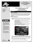
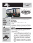
Installation & Service Manual Slim Rack Bunk Lift System with Control Box 1510000199 or 1510000260 © Copyright Power Gear Issued: January 2013 # 3010002675, Rev. 0D Installation and Service Manual Dual Planetary Gearmotor Slim Rack Bunk Lift System Content Introduction SYSTEM DESCRIPTION: The Power Gear Slim Rack Bunk Lift System is a rack and pinion design operated by a 12 Volt DC electric Motor. The system is designed to move a bunk of no more than 100 pounds vertically. Bunk Lift systems rated for higher weight or longer strokes can be obtained. Please contact Power Gear for application assistance. Figure 1 CONTENTS Introduction Installation Program Mode Installation Issues Operation Mode Preventative Maintenance Fault Diagnostics Troubleshooting Override Modes Wiring Diagram Warranty 1 1-3 3-5 5 5-6 6 6-7 6-7 7-8 9 10 NOTE Bunk lift systems are engineered to provide years of trouble free service. Changes to weight, stroke, weight distribution, rail position, controller, power supply, seals, etc, all have an effect on the performance of the system. In order to secure warranty coverage, each new application or changes to existing applications must be audited and approved by Power Gear with a signed document. Audits can be arranged by contacting your account representative. MAJOR COMPONENTS: • Touchpad control that mounts to the wall. It allows bunk movement and provides end user feedback. • A specially designed control that gives the user full control of bunk movement, up or down. The control has programmable stops that stop the motor when the bunk is fully raised or lowered and the ability to detect faults for ease in troubleshooting. • Vertical channel (two to four) with 12V DC gear motor which mounts to bunk, and gear rack arms that mount to the vertical structure. • Harnesses to connect touchpad and motors to control box (sold separately). • Bunk Lift Systems are equipped with a manual override that allows you to raise/lower the bunk in the event of a loss of power. Installation GENERAL REQUIREMENTS: • Power input and wiring size must be such that there are no less than 10.5 running volts supplied at the motor leads under maximum load. • To ensure long, trouble free life of the bunk lift system, a maximum amp draw per motor should be less than 40% of motor stall. The system will operate at higher loads/amp draws but system component life will be reduced as the amp draw per motor is increased above the rating. Contact Power Gear with motor part number for more information on stall specs. • Bunk lift system controls must be supplied from Power Gear. Controls supplied by other companies will void warranty. • Voltage supply must come from a 12VDC automotive/RV type battery. th 1217 E. 7 St. Mishawaka, IN 46544 www.powergearus.com Page 1 of 10 3010002675 Installation and Service Manual Slim Rack Bunk Lift System Power Gear Bunk Lift System Components MOTOR CHANNEL GEAR RACK Vertical Channel and Mounting Flange CONTROL TOUCHPAD RACK END BRACKETS Figure 2 Installation (Continued) Mechanical Components: 1. See Figure 2 above for components of the bunk lift system. Harnesses not shown. 2. Secure bunk lift motor channel assembly to O.E.M supplied bed frame assembly. 3. Position bunk rack assembly against vertical structure, makes sure the gear rack is vertically positioned, and use a builder's level against gear rack to ensure gear rack is plumb. 4. Secure top rack/end brackets to a vertical structure. NOTE: Secure using four (4) flat head #10 screws (See FIGURE 3 below) into a structure that can support the weight of the bunk and sleeping occupants. 5. Using the builder's level make the gear rack is plumb, secure the bottom rack /end brackets to the vertical structure. Use four (4) flat head #10 screws. 6. Repeat steps 2-5 for attaching motor channel assembly and rack/end bracket assembly to other end of the bunk. Figure 3 FIGURE Figure 4 5 Bunk Lift Touchpad Touchpad Figure 5 Touchpad Harness assemblies Page 2 of 10 3010002675 Installation and Service Manual Slim Rack Bunk Lift System Installation (Continued) Wire Gauge 16 14 12 10 Maximum Length 10 feet 15 feet 25 feet 40 feet Wire must be sized so that a minimum of 12.5 VDC is measured at the control while under a load. . Figure 6 Information is given as reference only Electrical Components: 1. Mount the CONTROL BOX (FIGURE 1, page 1) in a clean and dry, weather tight location that will keep it from being damaged, but is easily accessible for service. The control is not waterproof. 2. Reference page 9 (FIGURES 14, 15, 16, 17, & 18) for wiring details. 3. Determine location to mount TOUCHPAD (FIGURE 4, page 2). Location needs to be in view of bunk lift and have minimum depth of 1” inside the wall. Cut a 3 1/8” wide by 2” high rectangular opening in the wall paneling to mount the touchpad. 4. Route and attach the touchpad harness (FIGURE 5) to the touchpad where the touchpad will be mounted. After system has been programmed (see PROGRAM MODE, page 4), mount TOUCHPAD (FIGURE 4) with two (2) screws. 5. Route the motor/sensor harnesses from the bunk lift motors to the control box. Mark the motor leads at both ends to aid in connections after routing harness. Note: It is important that the bunk lift motors be plugged in to the proper receptacle at the control box. Please see the FIGURE 7 below for proper bunk lift motor designation. Failure to properly connect the motors to the control will result in programming issues (see FAULT DIAGNOSIS/TROUBLESHOOTING, page 6). 5. Route and attach the proper gauge wires (FIGURE 6) from the control to the 12V DC battery using a 30A fuse or circuit breaker. Installation of the bunk lift is now complete. You are now ready to program the up and down stops (see PROGRAM MODE, page 4). Possible Bunk Lift Locations Figure 7 Road side B A C K M1 BUNK M1 M2 BUNK M2 BUNK M1 F R O N T M2 Curb side Proper designation of motor locations M1 = Motor 1 M2 = Motor 2 Page 3 of 10 3010002675 Installation and Service Manual Slim Rack Bunk Lift System WARNING • • Always make sure that the bunk lift path is clear of people and objects before and during operation of the bunk. Always keep away from the gear racks when the bunk is being operated. The gear assembly may pinch or catch on loose clothing causing personal injury. Program Mode Use this procedure to initially set the UP and DOWN stops or to change the current stop settings. Note: At any time during the program procedure, the unit will exit program mode if the bunk has not been moved for two (2) minutes or if a fault is detected during programming. The FAULT CODE and BUNK LIFT MOVEMENT LED’s will flash rapidly for 10 seconds to indicate that the programming procedure failed. After the 10 seconds of flashing, the control will automatically default to FAULT CODE 1 (see FAULT CODES, page 7) and programming must be restarted. 1. If the TOUCHPAD (FIGURE 4) is mounted to the wall, remove it to access the buttons (FIGURES 8 & 9) on the back side. 2. Press and hold the SET STOPS/CLEAR FAULT (FIGURE 8) button on the back of the bunk lift touchpad for five (5) seconds. The FAULT CODE and BUNK LIFT MOVEMENT LED’s will light while the button is held down. • After five (5) seconds, the GREEN LED will begin flashing and the RED LED will remain lit (FIGURE 10). 3. You are now ready to set the UP stop. The UP stop must be programmed first. a. Press and hold the bunk lift motor buttons (MOTOR 1 and MOTOR 2, FIGURE 9) on the back of the bunk lift TOUCHPAD (FIGURE 4) that correspond to the bunk lift motors you want to move. These buttons correspond to the bunk lift motors. b. Press the UP button on the front of the bunk lift TOUCHPAD. c. Move the bunk lift to the fully raised position. Release buttons. Press and release the SET STOPS/CLEAR FAULT (FIGURE 9) button on the back of the bunk lift touchpad to program the UP stop position. The RED LED will now start to flash and the GREEN LED (FIGURE 10) will remain lit. Figure 8 Set Stops/Clear Fault Button Figure 9 Bunk Lift Motor Buttons Figure 10 Bunk Lift Touchpad Programming Lights Page 4 of 10 3010002675 WARNING Installation and Service Manual Slim Rack Bunk Lift System Program Mode (Continued) 4. • Always make sure that the bunk lift path is clear of people and objects before and during operation of the bunk lift. • Always keep away from the gear racks when the bunk lift is being operated. The gear assembly may pinch or catch on loose clothing causing personal injury. 5. You are now ready to set the DOWN stop. a. Press and hold the same bunk lift motor buttons (MOTOR 1 and MOTOR 2) as you did in STEP 3a, page 4. b. Press the DOWN button on the front of the wall TOUCHPAD (FIGURE 10, page 4). c. Move the bunk to the fully lowered position. Release the buttons. d. Press and release the SET STOPS/CLEAR FAULT (FIGURE 8, page 4) button on the back of the bunk lift touchpad to program the down stop position. • If both LED’s flash rapidly for one (1) second and then shut off, the control has been programmed correctly and is now in normal operation mode. • If both LED’s flash rapidly for 10 seconds, the control has NOT been programmed correctly or the system is wired incorrectly. The TOUCHPAD (FIGURE 4, page 2) will flash the fault code that occurred during programming. Refer to the FAULT DIAGNOSTICS/TROUBLESHOOTING section (page 6), repair the fault, and repeat the PROGRAM MODE procedure starting with STEP 1, page 4. • The control must be programmed correctly before it will operate in normal mode. NOTE: The UP stop must be programmed before the DOWN stop. Re-install the bunk lift TOUCHPAD (FIGURE 4, page 2). Programming of the control is now complete. Installation Issues The control is equipped to help troubleshoot the system during installation. Count the number of LED flashes and refer to the FAULT DIAGNOSTICS/TROUBLESHOOTING section starting on page 6 of this manual. If you are still having difficulties programming the system (and prior to replacing the control), verify that the system has been wired correctly and that the UP stop location was programmed before the DOWN stop location. See FIGURE 7, page 3 for proper connection of the motors to the bunk lift control. Operation Mode Please note: • The bunk lift system will not function until the stops are properly set or faults are cleared. • The GREEN LED (FIGURE 11, page 4) indicates the system operation. A solid GREEN LED indicates bunk movement. • The RED LED (FIGURE 11, page 4) indicates a fault or a problem with the system. Refer to the FAULT DIAGNOSTICS/TROUBLESHOOTING (page 6) for additional information. Prior to moving the bunk lift: • Make sure the engine or generator is running to ensure ample voltage is being supplied to the bunk lift system motors. • Make sure bunk path is clear of obstructions. th 1217 E. 7 St. Mishawaka, IN 46544 www.powergearus.com Lowering the bunk: 1. The engine or generator must be running, or plugged into shore power. 2. Transmission must be in PARK or NEUTRAL. (If applicable). 3. Level the unit. 4. Remove the locking pins. (If applicable). 5. Turn “on” the on/off switch or key. (If applicable). 6. Press and hold the DOWN button (FIGURE 10, page 4). There will be a slight delay before the bunk will begin to move, this is normal. 7. Release the button when the bunk is fully lowered and stops moving. 8. Turn “off” the on/off switch or key. (If applicable). Page 5 of 10 3010002675 WARNING • Always make sure that the bunk lift path is clear of people and objects before and during operation of the bunk lift. • Always keep away from the gear racks when the bunk lift is being operated. The gear assembly may pinch or catch on loose clothing causing personal injury. Installation and Service Manual Slim Rack Bunk Lift System Operation Mode (continued) Raising the bunk: 1. The engine or generator must be running, or plugged into shore power. 2. Transmission must be in PARK or NEUTRAL. (If applicable). 3. Level the unit. 4. Turn “on” the on/off switch or key. (If applicable). 5. Press and hold the “in” button (FIGURE10, page 4). 6. Release the button when the bunk is fully in raised position. 7. Turn “off” the on/off switch or key. (If applicable). 8. Install the locking pins. (If applicable). Preventative Maintenance Your Power Gear bunk lift system has been designed to require very little maintenance. To ensure the long life of your bunk lift system, read and follow these few simple procedures: • • When the bunk is in the down position, visually inspect the gear rack assemblies. Check for excess build up of dirt or other foreign material; remove any debris items that may be present. If the system squeaks or makes any noises, blow out any debris from the gear rack arms and apply a dry lubricant to prevent and/or stop squeaking. If you have any problems or questions, please see the contact tab on our website at www.powergearus.com Fault Diagnostics/Troubleshooting This control has the ability to detect and display several faults. When a fault is detected, the bunk movement will stop and two (2) different LED’s will flash in a pattern. • The FAULT CODE LED (FIGURE 10, page 4) will flash RED a number of times corresponding to a specific fault code. Refer to the TROUBLESHOOTING chart on page 7 to best determine what caused the fault. • The BUNK MOVEMENT LED (FIGURE 10, page 4) will flash GREEN a number of times corresponding to which motor had the associated fault. For example: if you are seeing four (4) RED flashes and two (2) GREEN flashes, it means that there is a motor fault on motor 2. There are two (2) types of faults, MINOR and MAJOR, and fault must be cleared in order for the bunk to operate. • MINOR faults can be cleared by pushing and releasing the UP or DOWN buttons on the bunk lift touchpad (FIGURE 10, page 4). • After the problem has been repaired, MAJOR faults must be cleared by pushing and releasing the SET STOPS/CLEAR FAULTS button located the back of the bunk lift touchpad (FIGURE 8, page 4). Note: For major faults, the control must be overridden by following the EMERGENCY BUNK MOVEMENT in the OVERRIDE MODES section on starting on page 7. The control will then have to be re-programmed by the O.E.M authorized dealer when the problem is repaired. A listing of FAULT CODES including probable causes and possible solutions begins on page 7. th 1217 E. 7 St. Mishawaka, IN 46544 www.powergearus.com Page 6 of 10 3010002675 Installation and Service Manual Slim Rack Bunk Lift System Fault Diagnostics/Troubleshooting (continued) FIGURE 11 FAULT CODES Fault Code Fault Type Description 1 Major Stops not programmed • • • Stops have not been set Stops were cleared Stops were improperly set 2 Minor System Fault • • Obstruction present Excessive system drag 4 Major Motor Fault • • Bad wire connection Bad motor 6 Minor Excessive Battery Voltage Supply voltage to control is 17 V DC or greater. Possible Cause Possible Solutions Stops need to be programmed according to the PROGRAM MODE instructions starting on page 3. Run bunk lift in opposite direction. If bunk continues to move in the opposite direction, remove obstruction, excessive weight in bunk or repair of damaged component. If bunk stops moving in opposite direction, observe fault code and refer to this chart. Refer to TIP Sheet 82-S0530 for troubleshooting.* Consult manufacturer of unit charging system for troubleshooting assistance. Override Modes *This tip sheet and other updated troubleshooting information can be found on our website at www.powergearus.com. In the event of component failure or loss of system power, your bunk can be manually overridden and bunk moved for travel. Note: At any time during the override procedure, the unit will exit this mode if the bunk has not been moved for two (2) minutes or if a fault is detected during bunk movement. The FAULT CODE and BUNK MOVEMENT LED’s will flash rapidly for 10 seconds to indicate that the override procedure failed. After the 10 seconds of flashing, the control will automatically default to FAULT CODE 1 (see FAULT CODES, FIGURE 11) and programming must be restarted. Note: The bunk control will need to be re-programmed by an authorized dealer after the system has been overridden. A. EMERGENCY BUNK MOVEMENT TO UP POSITION: Use this procedure when there is NO loss of power or electrical problem with the system. # of RED flashes # of GREEN flashes Figure 12 1. 2. 3. 4. Remove the touchpad (FIGURE 4, page 2) from the wall. Prior to clearing the MAJOR fault, record the number of RED and GREEN flashes (FIGURE 12) observed on the touchpad. This information will help your dealer/service center in troubleshooting the bunk lift system. Press and hold the SET STOPS/CLEAR FAULTS button (FIGURE 8, page 4) on the back for the touchpad for five (5) seconds. Both RED and GREEN LED’s will be on solid while this button is pressed. After five (5) seconds, the GREEN LED will begin flashing and the RED LED will remain lit. The unit is now ready to raise the bunk. Press and hold the BUNK LIFT MOTOR buttons 1 and 2 on the back of the TOUCHPAD (FIGURE 9, page 4). Caution: It is very important to note that during this procedure, the bunk lift control has NO stop locations. Damage to the bunk lift can occur if the bunk is raised or lowered too far. 5. th 1217 E. 7 St. Mishawaka, IN 46544 www.powergearus.com Press the UP button on the front of the wall touchpad until the bunk is fully raised position. If one side of the of the bunk needs to be raised further in order to fully raise, press and hold the motor button corresponding to only the motor you want to move. Press the UP button on the front of the touchpad to raise the bunk the remainder of the way. Install lock pins Step 6 continued on page 8 Page 7 of 10 3010002675 WARNING • Always make sure that the bunk lift path is clear of people and objects before and during operation of the bunk. • Always keep away from the gear racks when the bunk lift is being operated. The gear assembly may pinch or catch on loose clothing causing personal injury. Installation and Service Manual Slim Rack Bunk Lift System Override Modes (continued) 6. 7. Re-install the wall touchpad. Take the unit to a coach manufacturer dealer for repairs. B. MANUAL EMERGENCY BUNK MOVEMENT TO UP POSITION. Use this procedure when the above procedures do not work. In the event that power is lost to the bunk motor(s) or OVERRIDE MODE “A” (page 7) will not work, the bunk can be manually raised by following these steps: 1. Use a voltmeter and check to see if power is being delivered to the control module. 2. If no DC power is being delivered from coach, use another 12 VDC battery power source to power the module and retract the bunk using the UP button on the touchpad. 3. If power source is not available, then use the following steps: a. Gain access to motor channel on each side of the O.E.M bunk frame by first removing the mattress. b. Remove the O.E.M top cover plate of each bunk frame channel assembly. c. Loosen motor retainer screw or motor retainer spring. Do not remove the screw. (FIGURE 13) d. Remove each motor from the channel assembly. Bunk will drop if in the raised position. e. Disconnect motor connectors and place motors in a safe location. They will be needed when bunk lift is serviced. f. Manually push up bunk lift. 4. When bunk in fully raised position, install pins to keep it in place. Note: The bunk lift will have to be inspected at a coach manufacturer dealer for troubleshooting and repairs. The bunk control will need to be re-programmed by a coach manufacturer dealer after the system has been overridden. Motor retainer screw Motor retainer spring Figure 13 Figure 13 th 1217 E. 7 St. Mishawaka, IN 46544 www.powergearus.com Page 8 of 10 3010002675 Installation and Service Manual Slim Rack Bunk Lift System Wiring Information Note: See FIGURE 18 below for touchpad reference to pins 2, 3, 9, 10, 11, and 12. Figure 14 1510000195 Control to touchpad harness Figure 15 Figure 16 Power harness- Molex Minifit Sr. PN: 42816-0212 1510000194 control to motor harness Parking brake connector Figure 17 th Control Box 1510000199 or 1510000260 1217 E. 7 St. Mishawaka, IN 46544 www.powergearus.com Figure 18 Touchpad. Reference of pins 2, 3, 9, 10, 11, and 12 from FIGURE 14 above. Page 9 of 10 3010002675 Installation and Service Manual Slim Rack Bunk Lift System Additional Reference publications located at www.powergearus.com 3010002678 82-S0530 82-S0531 82-S0532 Owner's manual slim rack bunk lift system with control box 1510000199 or 1510000260 Trouble shooting Bunk Lift control box 1510000199 or 1510000260 for In-Wall Slim Rack Systems Encoder Test 1 Dual Planetary Gear Motor Sync with Control Box 1510000199 or 1510000260 Encoder Test 2 Dual Planetary Gear Motor Sync with Control Box 1510000199 or 1510000260 Power Gear Limited Warranty Power Gear Limited Warranty Policy (Original equipment) Power Gear warrants its manufacturer installed Power Gear and Kwikee brand products to be free of material and workmanship defects for two (2) years from the date of the original sale of the motor vehicle/recreation vehicle (RV) in which they are installed, provided that these products are installed and operated according to the purpose for which they were intended, designed and specified. This warranty does not cover product that is incorrectly installed, or upon examination has been misused or abused by the vehicle owner. Warranty coverage includes: • Repair or replacement of the defective component(s) of the malfunctioning system. Entire systems are not replaced unless either the faulty component is not replaceable or all components comprising the system are defective. • Labor costs for the diagnosis and repair work associated with the repair or replacement of the defective component(s) by a licensed servicing center. This warranty does not include payment or reimbursement of: • Normal system maintenance and preventive maintenance. • Mobile service or towing expenses related to field repairs and/or the transportation of the vehicle to a repair facility. • Living or travel related expenses incurred in the repair of the vehicle. By filing a warranty claim in accordance with Power Gear’s Warranty Administration Procedure, service providers agree that the replacement part(s) will be provided to the vehicle owner at no cost and that the total labor charges for the completion of warranty repairs will be billed to Power Gear. Accordingly, under no circumstances will Power Gear reimburse the vehicle owner directly for costs covered under this warranty policy. Warranty coverage runs concurrently with any vehicle warranty period provided by the manufacturer, and is transfer-able to subsequent owners. Proof of original date of purchase of vehicle, and if applicable subsequent owner’s proof of purchase, is required to confirm coverage. Power Gear reserves the right to change the terms of our warranty policy at any time. For the most current information on product warranty and our warranty claim procedure, visit our website at www.powergearus.com. Page 10 of 10