1
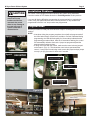
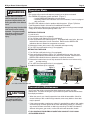
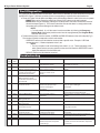
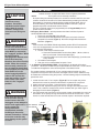
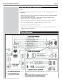
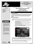
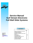
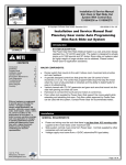
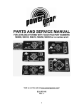
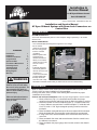
Installation &
Service Manual
for M² Sync Slideout Control
Box #1510000122
© 01/13 Power Gear #3010001343 Rev. 0C
Installation and Service Manual
M² Sync Slideout System with Room Lock Connectors on
Control Box
Introduction
SYSTEM DESCRIPTION
Your Power Gear Slideout System is a rack and pinion design operated by a 12 Volt DC
electric motor.
MAJOR COMPONENTS
CONTENTS
Introduction
Installation
Installation Problems
Program Mode
Operation Mode
Preventative Maintenance
Fault Diagnostics
Troubleshooting
Override Modes
Wiring Diagram
Warranty
1
1
2
2-3
4
4
5
5
6-7
7
8
! WARNING
Always keep away from the
slide-out room and rails when
the room is being operated. The
gear assembly may pinch or
catch on loose clothing causing
personal injury
Failure to follow these instructions could result in serious
injury or death
1217 E. 7th Street
Mishawaka, IN 46544
powergearus.com
gearmotor will operate
Motor Rotation
the room using power
Dip Switch
from the on-board
unit battery.
equipped with a
manual override that
allows you to extend /
retract the room in the
event of a loss of
power.
!
control that gives the
user full control of room
movement, in
!
programmable stops
Figure 1
that stop the motor
when the room is fully
extended or retracted and the ability to detect faults for ease in troubleshooting.
ck Jum
Room Lo
pers
Installation
"$%&
!!'(
)**&'
'
+89
P/N 81-1291) for proper installation of rail assemblies.
$
!=>$89?@ABAA9$
installation of room locks.
Control and touchpad Installation. Refer to proper wiring diagram in back of manual
'!
F+HJ
!
!!)
nents from the elements and being hit but is easily accessible for service.
!!+HBJK!
in view of slideout room and have a minimum depth of 1” inside the wall.
Cut 2 7/8“ wide x 1 3/4” high rectangular opening in wall to mount the
touchpad.
3. Route and attach touchpad harness to where touchpad will be mounted.
'!+J!$
4. If using room locks, route and attach room lock harness from control to
room lock.
5. Route and attach the motor and sensor harness from the control box to
the slideout room motors.
6. Route and attach the proper gauge wire from the control to the chassis
battery.
M²-Sync Room Slideout System
! CAUTION
During Program mode the
control has no stop
locations and the user
must teach the control
where to stop. Damage to
the room may occur if
system is extended or
retracted too far.
Figure 2
Figure 3
JUMPED
Page 2
Installation Problems
The control is also equipped to help troubleshoot the system during installation.
Count the number of LED flashes and refer to Fault Diagnostics section previous.
If you are still having difficulties programming the system and prior to replacing the
control, verify the system has been wired correctly and the “in” stop location was
programmed before the “out” stop location was programmed.
Program Mode
Use this procedure to initially set the IN and OUT stops or to change the current stop
settings:
NOTE:
• At anytime during the program procedure, the unit will exit program mode if
the room had not been moved for 45 seconds or if a fault is detected during
programming, the LED will flash rapidly for 10 seconds to indicate that the
programming procedure failed. After the 10 seconds of flashing, the control
will automatically default to fault code 1 (stops not programmed) and the
program mode must be re-done.
• If using room locks with this control, make sure the room locks are jumped
on the board. (Fig 1-2). This allows the room locks to operate with the
control. If room locks are not being used, remove the jumper and put jumper
on only 1 pin (Fig 3) to save for future use if needed.
UNJUMPED
Left Hand Mounted Motor
Switch Location (6B)
Slideout Motor Direction
Switches
Right Hand Mounted Motor
Switch Location (6C)
Figure 6A
Figure 6C
Figure 6B
LEFT HAND
MOUNTED MOTOR
RIGHT HAND
MOUNTED MOTOR
RAIL ASSY
RAIL ASSY
M²-Sync Room Slideout System
Page 3
Program Mode, continued....
! CAUTION
Use caution when
initially programming
the control as the
correct motor rotation
must be determined
and programmed with
the control (Ref. Step
2). Damage to the
room or system may
result. Once control
has been programmed
correctly, this step will
not need to be
repeated.
1. Locate the control (Fig 1) and verify which location the SLIDEOUT motors are plugged into
(Motor 1, Motor 2, Motor 3, and/or Motor 4)
2. This step will only need to be set when initially programming the slideout motor rotation on the
control. If you are resetting stop locations or the control has already been programmed, skip to
the next step.
• For initial programming of the slideout motors rotation, you need to determine each
slideout motor mounting orientation and locate the dip switches in the upper left hand
corner of the control. (fig 1 and 6A)
• Motor mounting orientation is determined by which side of the rail assembly the motor is
mounted on when viewed from the outside of the unit. (Fig 6B and Fig 6C).
• (Fig 6A) Switch 1 = Slideout Motor 1, Switch 2 = Slideout Motor 2, etc. Position the dip
switch in the left position for a left hand mounted slideout motor or in the right position for
a right hand mounted slideout motor.
• If during programming a motor runs in the opposite direction, locate the corresponding
dip switch and move to other position.
3. Remove the touchpad (Fig 7) from the wall.
4. Press and hold the “Set Stops/Clear Fault” button on the back of the wall touchpad for
5 seconds. (Figure 4). Both LED’s will light while the button is held down. (Figure 7)
Note:
• After 5 second, the GREEN LED will begin flashing and the RED LED will remain lit.
• If the room is equipped with room locks and the room locks are extended, the room
locks will retract automatically.
5. The unit is now ready to set the retracted or IN stop. Referring to the information you wrote
down in step 1 above,
a. Press and hold the SLIDEOUT room motor buttons (Motor 1, Motor 2, Motor 3, and/or
Motor 4) on the back of the wall touchpad (Fig 3) that correspond to the SLIDEOUT
motors you want to move. These buttons correspond to the slideout room motors only
and NOT the room lock motors.
b. Press the In or OUT button on the front of the wall touchpad depending upon direction
of rail movement you desire.
c. Move the room to the fully retracted position.
d. Press the “Set Stop/Clear Fault” button on the back of the wall touchpad to program
the retracted stop position.
Note:
• The RED LED will now begin flashing and the GREEN LED will remain lit.
6. The unit is now ready to set the extended or OUT stop. Referring to the information you wrote
down in Step 1 above,
a. Press and hold the same SLIDEOUT motor buttons (Motor 1, Motor 2, Motor 3, and/or
Motor 4) as you did in the prior step.
b. Press the IN or OUT button on the front of the wall touchpad depending upon direction
of rail movement you desire.
c. Move the room to the fully extended position.
d. Press the “Set Stop/Clear Fault” button on the back of the wall touchpad to program the
extended stop position.
Note:
• The control must be programmed correctly before it will operate in normal mode.
• If both LED’s flash rapidly 3 times and turn off, the control has been programmed
correctly and is now in normal operation mode.
• If both LED’s flash rapidly for 10 seconds, the control has NOT been programmed
correctly or the system is wired incorrectly. The touchpad will flash the fault code that
occurred during programming. Fix the fault and repeat the Programming Mode
procedure starting with step 3 above. If the “Set Stops / Clear Fault” button on the back
of the wall touchpad is pressed and released, the control will default to Fault Code 1
indicating you must program the control.
7. Re-install the wall touchpad. Done.
M²-Sync Room Slideout System
! WARNING
Page 4
Operation Mode
Note:
▪ The system will not work until stops are properly set or faults are cleared.
▪ The GREEN LED indicates system operation. (Figure 7)
Always make sure that the
◦ A solid GREEN LED indicates room movement
slideout room path is clear of
◦ A flashing GREEN LED indicates room lock movement, if room is equipped
people and objects before and
with room locks.
during operation of the slideout
▪
The
RED
LED indicates a fault or problem with the system. (Figure 7) Refer to
room.
Fault Diagnostics Mode in this manual for additional information.
Always keep away from the slide ▪ Prior to moving the slideout room, make sure the engine is running to ensure ample
voltage to the motors and the parking brake is set.
rails when the room is being
operated. The gear assembly
EXTENDING THE ROOM
may pinch or catch on loose
1. Level the unit.
clothing causing personal
2. Remove transit bars (if so equipped).
injury.
3. Turn ‘ON’ the on/off switch or key (if so equipped).
4. Press and hold the OUT button (Figure 7). If equipped with room locks, the room
locks will first retract prior to room movement. Reference the GREEN LED
indications above to determine component movement.
5. Release the button, when room is fully extended and stops moving.
6. Turn 'OFF' the on/off switch or key (if so equipped).
RETRACTING THE ROOM
Figure 4
1. Turn 'ON' the on/off switch or key (if so equipped).
2. Press and hold the IN button (Figure 7) If equipped with room locks, the room
locks will automatically extend when the room is fully retracted. Reference the
GREEN LED indications above to determine component movement.
3. Release the button when room is fully retracted or when the room locks are fully
extended
nd
ded
e and stop moving.
4. Turn 'O
''OFF'
FF' the on/off switch or key (if so equipped).
5. Install
all the transit bars (if so equipped).
GREEN
Figure 3
SET STOPS/CLEAR FAULT BUTTON
SLIDEOUT ROOM
MOTOR BUTTONS
RED
LED
IN
BUTTON
LED
Figure 7
OUT
BUTTON
Preventative Maintenance
! CAUTION
Do not work on your slide
out system unless the
battery is disconnected
Your Power Gear slide-out system has been designed to require very little
maintenance. To ensure the long life of your slide-out system read and follow these
few simple procedures.
• When the room is out, visually inspect the inner slide rail assemblies. Check for
excess build-up of dirt or other foreign material; remove any debris or items that
may be present.
• If the system squeaks or makes any noises it is permissible to apply a light coating
of silicone spray or lithium grease to the roller and bearing sleeve I.D., removing
any excess lubricant so that dirt or debris do not build-up. DO NOT lubricate the
slide-out drive gears, gear racks, or roller OD as this will attract dirt / debris.
IF YOU HAVE ANY PROBLEMS OR QUESTIONS CONSULT YOUR LOCAL
AUTHORIZED DEALER
M²-Sync Room Slideout System
Page 5
Fault Diagnostics
The control has the ability to detect several faults. When a fault is detected, the room movement will stop and
the RED LED (Figure 7) will flash a number of times corresponding to a specific fault code listed below.
● There are 2 types of faults (Minor and Major) and a fault must be cleared in order for the room to operate.
◦ MINOR faults can be cleared by pushing the ‘IN’ and ‘OUT’ buttons on the wall touchpad
◦ MAJOR faults must be cleared by pushing the ‘Set Stop/Clear Fault’ button located on the back of
the wall touchpad (Figure 4). This is done to alert the end user that there is a major problem with
the system and to prevent damage to the slideout room.
NOTE:
▪ For fault codes 8, 9, or 10 the control must be overridden by following the Emergency
Retract Mode (listed below) and the control must be reprogrammed (See Program Mode)
when the fault is fixed.
● To determine the fault, count the number of GREEN and RED LED flashes on the wall touchpad (Fig 7)
The number of flashes corresponds to a fault code number.
◦ GREEN LED refers to the fault that has occurred with a specific motor. Example:1 LED flash
represents motor 1; 2 flashes represents motor 2; etc
NOTE:
▪ The only exception is with minor battery fault codes 2, 3, or 4. These faults apply to the
entire system and are not motor specific but the control will flash the GREEN LED once to
signify the start/end of the fault flash code.
◦ RED LED refers to the fault that has occurred.
Troubleshooting
Fault
Code
1
Fault
Type
Major
Description
Probable Cause
Possible Solutions
Stop Not Programmed
No stop locations has
been set for the control
Bad Battery, bad wire connection or short in system
Bad wire connection from
battery to control or low
battery
Bad battery
Set stop locations. Refer to Program Mode
procedures to set stops
Repair bad wire connection, short or replace
battery
Repair bad wire connection or replace battery
2
Minor
3
Minor
4
Minor
5
Minor
Excessive system/room drag,
obstruction, improper stop
locations or damaged
component
Shorted wiring or motor
Remove obstruction, re-adjust room, reset
stops, or replace damaged
component
6
Major
Slideout Motor Short
7
Major
Slideout Motor Open
8
Major
9
Major
10
Major
No signal on motor sensor
Out 1 (yellow) wire
No signal on motor sensor
Out 2 (blue) wire
No signal on motor sensor
wires yellow or blue
11
Minor
12
13
14
Battery Dropout Voltage.
Voltage dropped below 8.0V
Low Battery Voltage. Voltage
is below 10.5V when room
movement was initiated
Excessive Battery Voltage.
Battery Voltage is above
18.0V when room movement
was initiated.
Slideout motor drawing
excessive current
Replace battery
Bad connection, motor or
blown fuse.
Bad wire connection or sensor
Inspect motor harness wires and motor for
shorts. Replace shorted component.
Repair bad wire connection, replace motor
or fuse
Repair bad wire connection or replace motor
Bad wire connection or sensor
Repair bad wire connection or replace motor
Bad wire connection or sensor
Repair bad sensor or motor lead connections.
Lastly, replace motor.
Major
Room lock motor drawing
excessive current
Room lock motor short
Excessive drag or obstruction
or damaged component
Shorted wiring or motor
Major
Minor
Room lock motor open
Room lock timeout
Bad connection or motor
Bad wire connection,
obstruction, broken component
or low voltage
Remove obstruction or replace damaged
component
Inspect motor harness wires and motor for
shorts. Replace shorted component
Repair bad connection or replace motor
Remove obstruction, replace battery, repair
bad wire connection of fix broken component
in room lock
M²-Sync Room Slideout System
! CAUTION
Page 6
Override Modes
●●●●In the event of component failure of loss of system power●●●●
Your system can be manually overridden.
NOTE:
◦ At anytime during the override procedure, the unit will exit override mode if the room had
During override mode the
not been moved for 45 seconds or if a fault is detected during overriding, the LED will
control has no stop
flash rapidly for 10 seconds to indicate that the override procedure failed. After 10
locations. Use another
seconds of flashing, the control will automatically default to fault code 1 (stops not
individual to assist in deterprogrammed) and the override mode must be re-done.
mining when the room is
◦ The room control will need to be re-programmed (refer to Program Mode) after the
retracted. Damage to the
system has been overridden.
room can occur during over
1. Emergency Retract Mode - use this procedure when there is NO loss of power or
electrical problem with the system.
travel.
1. Remove the touchpad (Fig 7) from the wall
2. Press and hold the “Set Stops/Clear Fault” button on the back of the wall
touchpad for 5 seconds (Figure 4). Both LED’s will light while the button is
held down. (Figure 7)
NOTE:
◦ After 5 seconds, the GREEN LED will begin flashing and the RED LED will remain lit.
After the room has been
◦ If the room is equipped with room locks and the room locks are extended, the room
moved in the desired directlocks will retract automatically.
ion, the brake levers on each
3. The unit is now ready to retract the room.
motor MUST be returned to
a. Press and hold all SLIDEOUT motor buttons (Motor 1, Motor 2, Motor 3,
the "engaged" position. When
Motor 4) on the back of the wall touchpad (Fig 3)
the motor brake is
b. Press the IN button on the front of the wall touchpad (Fig 7) until the room
disengaged the slideout room
is fully retracted.
will not lock into place;
4. Re-install the wall touchpad.
therefore, the room will not be
5. Take your unit to a certified dealer for repairs. Done
sealed. When the room has
2. -or- Emergency Retract Module (ERM) - This procedure is an alternate to the above
been manually retracted, be
procedure. This kit (P/N 1010001197) can be purchased from Power Gear. The kit contains
sure to install the transit bars
a module that will bypass the control and send power to the slideout motors.
! WARNING
(if so equipped) and return the
motor brake lever to its
normal engaged position in
order to seal and lock the
room into position. Do not
travel unless each motor
brake is in the "engaged"
position!
! WARNING
The system has been equipped with ¾” hex override couplers located on a drive
component of the system. Due to the size and weight of some rooms, assistance may
be needed and care taken during the process. Use the following steps to mechanically
operate the room:
1. Locate the motor and ¾” hex coupler. (Figure 8) The hex coupler may not be
attached to the motor as pictured but attached to a system drive component.
2. Unplug each motor connector. Leave the sensor connector attached.
3. With your thumb, depress the spring lock lever on the right hand side of the boot
cover. Then, rotate the override lever counter-clockwise with your index finger to
disengage the motor brake. (Figure 9)
4. If enough people and wrenches for each override coupler are available, the room can
be moved in or out quickly as long as all shafts are turned at the same time. Use a
wrench or socket and ratchet to turn each override coupler in the direction required.
If the room has been moved
while the motor sensing
control harness has been
SENSOR
unplugged, do not attempt to
use the room again until a MANUAL OVERRIDE CONNECTOR
service center has
¾” HEX COUPLER
reprogrammed the
computerized controller
according to the service
manuals instructions. Failure
to reset the controller may
cause damage to the system
or coach.
Lock Lever
BRAKE LEVER
UNDER BOOT
Brake Lever
Figure 8
Figure 9
MOTOR
CONNECTOR
Engage
Disengage
M²-Sync Room Slideout System
Page 7
Override Modes, continued....
NOTE:
If only one or two people are available to move the room, the following procedure must
be followed:
• Start at the front of the coach, release the motor brake, rotate the shaft approximately
1/8 turn, re-apply the motor brake.
• Proceed to the next rail with motor. Release the motor brake, rotate the shaft
approximately 1/8 turn, re-apply the motor brake.
• Repeat this procedure until the room has been fully opened or closed as desired.
5. Once room is fully retracted, re-engage brake lever on motor. (Fig 9)
6. Re-connect the motor leads to the connector.
7. Take the unit to an authorized dealer for service. Do not use the slideout room as
damage to the room may result.
Wiring Diagram
M²-Sync Room Slideout System
Page 8
Power Gear Limited Warranty
Power Gear Limited Warranty Policy
(original equipment)
Power Gear warrants its manufacturer installed Power Gear and Kwikee brand products to be free of material and
workmanship defects for two (2) years from the date of the original sale of the motor vehicle in which they are
installed, provided that these products are installed and operated according to the purpose for which they were
intended, designed and specified. This warranty does not cover product that is incorrectly installed, or upon examination has been misused or abused by the vehicle owner.
Warranty coverage includes:
Pow
·
Repair or replacement of
the defective component(s) of the malfunctioning system. Entire systems are not
replaced unless either the faulty component is not replaceable or all components comprising the system are
defective.
·
Labor costs for the diagnosis and repair work associated with the repair or replacement of the defective
component(s) by a licensed servicing center.
This warranty does not include payment or reimbursement of:
·
Normal system maintenance and preventive maintenance.
·
Mobile service or towing expenses related to field repairs and/or the transportation of the vehicle to a repair
facility.
·
Living or travel related expenses incurred in the repair of the vehicle.
By filing a warranty claim in accordance with Power Gear’s Warranty Administration Procedure, service providers agree
that the replacement part(s) will be provided to the vehicle owner at no cost and that the total labor charges for the
completion of warranty repairs will be billed to Power Gear. Accordingly, under no circumstances will Power Gear
reimburse the vehicle owner directly for costs covered under this warranty policy.
Warranty coverage runs concurrently with any vehicle warranty period provided by the manufacturer, and is transferable to subsequent owners. Proof of original date of purchase of vehicle, and if applicable subsequent owner’s proof
of purchase, is required to confirm coverage.
Power Gear reserves the right to change the terms of our warranty policy at any time. For the most current information on product warranty and our warranty claim procedure, visit our website at www.powergearus.com.
Additional Reference Documents
Additional Reference Documents located at www.powergearus.com:
3010001344:
Owner’s Manual for Slideout Control Boxes 1510000122, 1510000143 and 1510000198.
82-SO521:
Encoder Test 1: Dual Sync Slide Controllers (M²) 1510000122, 1510000143 and 1510000198
82-SO522:
Encoder Test 2: Dual Sync Slide Controllers (M²) 1510000122, 1510000143, and 1510000198