1
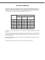
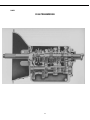
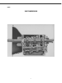
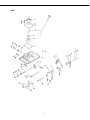
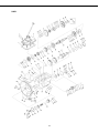
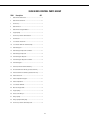
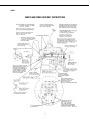
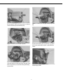
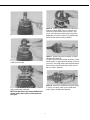
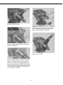
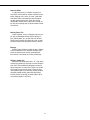
Fuller® Mid Range Transmissions
More time on the road ®
Service Manual
Fuller Mid Range Transmissions
TRSM0197
October 2007
Caution Before towing the vehicle, be sure to lift the rear wheels off the
ground or disconnect the driveline to avoid damage to the
transmission during towing.
1
FOREWARD
This manual has been prepared to provide the customer and the maintenance personnel with information and instructions on the maintenance and repair of the CLARK® Transmission.
Extreme care has been exercised in the design, selection of materials and manufacturing of these units. The slight outlay in personal attention and cost required to provide regular and proper lubrication, inspection at stated intervals, and
such adjustments as may be indicated will be reimbursed many times in low cost operation and trouble free service.
In order to become familiar with the various parts of the transmission, its principle of operation, troubleshooting and
adjustments, it is urged that the service person study the instructions in this manual carefully and use it as a reference
when performing maintenance and repair operations.
Whenever repair or replacement of components parts is required, only Clark-approved parts as listed in the applicable
parts manual should be used. Use of “will-fit” or non-approved parts may endanger proper operation and performance
of the equipment. The Clark Equipment Company does not warrant repair or replacement parts, nor failures resulting
from the use thereof, which are not supplied by or approved by the Clark Equipment Company.
IMPORTANT: Always furnish the Distributor with the transmission serial and model number when ordering parts.
1
CL550 SERIES TRANSMISSION
The CL550 is a 5-speed forward, 1-speed reverse transmission of advanced design offering you the most efficient
torque capacity-to-weight ratio of any 5-speed transmission in its torque range. Two basic ratios are available as shown
in the table below. The CL551 ratio is designed for use in trucks equipped with a 3 or 4-speed auxiliary transmission
and the CL557 ration is designed for use with trucks equipped with a 2-speed rear axle.
MODELS
Speed
CL551/390V
CL557/397V
CL558
Fifth
Direct
Direct
Direct
Fourth
1.52:1
1.17:1
1.28
Third
2.54:1
1.99:1
2.15
Second
4.35:1
3.68:1
3.68
First
7.52:1
6.82:1
6.36
Reverse
6.27:1
5.30:1
5.30
Constant mesh in all gears, including low and reverse, is a CL550 feature as is helical gearing throughout, including low
and reverse.
The Clark split-pin synchronizer is used in 2nd, 3rd 4th and 5th gears. Greater bearing capacity in the CL550 is achieved
by the use of numerous needle roller bearings, and two tapered roller bearings and one large straight roller bearing at
the rear of the countershaft.
Shift forks have replaceable bronze inserts. The shift pattern is of the standard progression type with all shifts having
the same throw at the lever.
Page B shows a cutaway drawing of the CL550. Page C shows a cutaway drawing of the 390V.
A
CLARK
CL550 TRANSMISSION
B
CLARK
390V TRANSMISSION
C
THE CLARK SYNCHRONIZER
AND HOW IT WORKS FOR YOU
The Clark split-pin synchronizer prevents the clashing of the gears and increase the speed of shifting.
In a conventional transmission which does not have synchronizers the absence of gear clashing is dependent entirely
on the skill of the truck driver. By double-clutching and split second timing of engine speeds with the gear shifting
movement, a driver can synchronize the speeds of the engaging gears and thereby prevent the damage to gears by
clashing when a fast shift. The splint-pin sychronzier performs the same function with or without the “double-clutching”
operating even though the driver does not accurately time his gear shifting movements. It also mechanically prevents
the driver from completing the shift to the point of gear engagement until the engaging gears have reached the same or
synchronous speeds. This is known as the blocking action of the synchronizer and it is this action that makes the operation of shifting a transmission having synchronizers different from one which does not have synchronizers.
Upon shifting gears in these synchronized transmissions the first part of the gear shift lever movement brings the
blockers into contact. The blockers momentarily prevent further movement of the shift lever and the pressure exerted
by the driver to complete the movement, is transferred by the blockers to the synchronizer providing the force necessary to synchronize the gears being engaged. When the engaging gears have reached the same speed, the blockers
automatically disengage, permitting the gear shift lever movement to be completed. Therefore, to properly shift a synchronized transmission a steady and continuous pressure must be applied by the driver to the shift lever until the shift
is completed. Under normal conditions this action is instantaneous.
Sometimes difficulty is experienced in shifting a synchronizer when the vehicle is standing still. This is caused by the
fact that the disengagement of the blockers requires relative rotation and with the vehicle at rest and with the engine
clutch released, there may be at times, no relative rotation of the engaging gears. Under these conditions, the same continuous pressure should be applied to the shift lever and at the same time, the clutch should be engaged slightly. This
will give sufficient rotation to unblock the synchronizer and allow the shift to be completed without difficulty.
D
RECOMMENDED LUBRICANTS FOR CLARK
MANUALLY SHIFTED TRANSMISSIONS
*Mil-L-2105C Extreme Pressure Lubricant (or API classification GL-5)
of the SAE viscosity recommended in the chart at the right is preferred.
All lubricants should be backed by the reputation of a well-know supplier. It is important to specify EP lubricants of the MIL-L-2105C type
only, or of a API classification GL-5.
*Do not use extreme pressure lubricants other than MIL-L-2105C or
of a API classification GL-5.
Many EP lubricants contain highly-active chemical compounds that
have been formulated to perform satisfactorily in specific types of
applications. Severe corrosion, residual deposits, and inadequate
lubrication may result from improper application. Use of EP lubricants
other that MIL-L-2105C or of a API classification GL-5 may result in
failure and/or impaired operation.
DRAINING ECONOMY - The object in draining the transmission oil
periodically is to eliminate possible bearing surface abrasion and
attendant wear. Minute particles of metal, the product of normal wear
in service, are deposited in and circulate with the transmission oil. The
oil changes chemically, due to its repeated heating and cooling, also
the terrific churning it undergoes in the presence of air. It is desirable
to drain out this used oil after the first 1,000 miles (1609,0 Km) of service (regardless of type of service). Subsequent drains should be
made every 24,000 miles (38616,0 Km) or six (6) months (whichever
comes first) for highway service, and every 8,000 to 10,000 miles [12872,0-16090,0 Km] or six (6) months (whichever
comes first) “on-off” highway and “pick-up and delivery” types of service. Do this only when the transmission is thoroughly warm.
FLUSHING - After draining, flushing is desirable. Replace the drain plug and fill the transmission to the proper level with
a light flushing oil. Drive the transmission for a short period at fast idle in such a manner that the gears in the transmission are rotating without load. This washes out the old oil clinging to the interior of the gear case, covers and shifter
rails. BE SURE TO DRAIN OUT ALL of the flushing oil before attempting to refill with new oil. This flushing procedure is
most important after first drain.
REFILL - First, removal all dirt around the filler plug, Then refill with new oil of a grade recommended for the existing
season and prevailing service. Fill to the bottom of the level testing plug positioned on the side of the transmission. DO
NOT OVERFILL, as the excess quantity will serve no useful purpose. If the oil level is too high, it will cause excessive oil
churning and high oil temperature and possible leakage.
INSPECTION - Oil level inspection should be made every 6,000 miles [9654,0 Km] which usually coincides with the
vehicle manufacturers chassis lube procedure. Always clean around filler plug before inspection. Add sufficient oil to
maintain correct level.
E
CLARK
F
CapscrewCL550-SERIES TRANSMISSION
ITEM
DESCRIPTION
QTY.
1
Control Cover Gasket ...............................................................1
2
Lockwasher............................................................................14
3
Control Cover Screw ..............................................................14
4
Control Cover Assembly ..........................................................1
5
Mainshaft Reverse Gear Bearing Spacer ..................................1
6
Mainshaft Reverse Gear Roller Bearing..................................48
7
Mainshaft Reverse Gear Bearing Spacer ..................................1
8
Mainshaft Reverse Gear Roller Bearing..................................48
9
Mainshaft Reverse Gear ...........................................................1
10
1st & Reverse Shift Hub Sleeve ...............................................1
11
Shift Hub Sleeve Retainer Ring ................................................1
12
1st & Reverse Shift Hub ..........................................................1
13
Mainshaft 1st Gear Bearing Spacer..........................................1
14
Mainshaft 1st Gear Roller Bearing .........................................44
15
Mainshaft 1st Gear Bearing Spacer..........................................1
16
Mainshaft 1st Gear Roller Bearing .........................................44
17
Mainshaft 1st Gear...................................................................1
18
Split Washer Retainer Ring ......................................................1
18A - Mainshaft Rear Bearing Split Washer** ................1
19
Mainshaft Rear Bearing Cone...................................................1
20
Ball...........................................................................................1
21
Split Washer Retainer Ring ......................................................1
22
Mainshaft 2nd & Reverse Gear Split Washer ...........................2
23
Mainshaft 2nd Gear..................................................................1
24
Mainshaft 2nd Gear Bearing Spacer.........................................1
25
Mainshaft 2nd Gear Roller Bearing ........................................48
26
Mainshaft 2nd Gear Bearing Spacer.........................................1
27
Mainshaft 2nd Gear Roller Bearing ........................................48
28
Mainshaft .................................................................................1
29
2nd & 3rd Synchronizer Assembly ..........................................1
30
3rd Gear Synchronizer Cup ......................................................1
31
Mainshaft 3rd Gear Roller Bearing** .....................................48
32
Mainshaft 3rd Gear Bearing Spacer ** ....................................1
33
Mainshaft 3rd Gear Roller Bearing** .....................................48
34
Mainshaft 3rd Gear Bearing Spacer** .....................................1
35
Mainshaft 3rd Gear ..................................................................1
36
Ball**.......................................................................................1
37
Mainshaft 3rd Gear Locating Washer.......................................1
38
Mainshaft 3rd Gear Retainer Ring............................................1
39
Mainshaft 4th Gear Roller Bearing** .....................................34
40
Mainshaft 4th Gear Bearing Spacer**......................................1
41
Mainshaft 4th Gear Roller Bearing** .....................................34
42
Mainshaft 4th Gear ..................................................................1
43
4th & 5th Shift Hub Sleeve.......................................................1
G
ITEM
Description
QTY.
44
4th & 5th Synchronizer Cup.....................................................1
45
4th & 5th Synchronizer Assembly............................................1
46
4th & 5th Synchronizer Cup.....................................................1
47
4th & 5th Shift Hub Bearing ....................................................1
48
4th & 5th Shift Hub Bearing Race ............................................1
49
Name Plate Screw....................................................................2
50
Name Plate...............................................................................1
51
Countershaft Gear Retainer Ring .............................................1
52
Countershaft Drive Gear...........................................................1
53
Countershaft 4th Gear..............................................................1
54
Countershaft Gear Key .............................................................2
55
Countershaft ...........................................................................1
56
Oil Baffle ..................................................................................1
57
Countershaft Rear Bearing .......................................................1
58
Countershaft Rear Bearing Outer Retainer Ring.......................1
59
Countershaft Rear Bearing Retainer Ring ................................1
60
Countershaft Rear Bearing Cap Gasket ....................................1
61
Countershaft Rear Bearing Cap ................................................1
62
Lockwasher..............................................................................4
63
Rear Bearing Capscrew............................................................4
64
Mainshaft Rear Bearing Cup & Snap Ring ...............................1
65
Speedometer Drive Gear ..........................................................1
66
Mainshaft Rear Bearing Cap Gasket .........................................1
67
Mainshaft Rear Bearing Cap.....................................................1
68
Lockwasher..............................................................................3
69
Mainshaft Rear Bearing Capscrew ...........................................3
70
Mainshaft Rear Bearing Cap Oil Seal........................................1
71
Mainshaft Flange Nut ...............................................................1
72
Speedometer Tube Nut.............................................................1
73
Speedometer Driven Gear ........................................................1
74
Mainshaft Rear Bearing Capscrew ...........................................1
75
Lockwasher..............................................................................1
76
Reverse Idler Lockscrew..........................................................1
77
Reverse Idler Shaft Lock ..........................................................1
78
Reverse Idler Shaft ..................................................................1
79
Reverse Idler Thrust Washer ...................................................1
80
Reverse Idler Gear Bearing Spacer...........................................1
81
Reverse Idler Gear Bearing ....................................................26
82
Reverse Idler Gear ..................................................................1
83
Reverse Idler Gear Bearing Spacer...........................................1
84
Reverse Idler Gear Bearing ....................................................26
85
Reverse Idler Gear Bearing Spacer...........................................1
86
Reverse Idler Thrust Washer....................................................1
87
Mainshaft Spigot Bearing Washer Retainer Ring .....................1
ITEM
Description
QTY.
H
88
Mainshaft Spigot Bearing Washer............................................1
89
Mainshaft Spigot Bearing.......................................................14
90
Main Drive Gear ......................................................................1
91
Main Drive Gear Bearing Cone .................................................1
92
Main Drive Gear Bearing Cup ...................................................1
93
Main Drive Gear Bearing Shim ..............................................AR
94
Main Drive Gear Bearing Cap Oil Seal ......................................1
95
Main Drive Gear Bearing Cap ...................................................1
96
Lockwasher..............................................................................4
97
Bearing Capscrew ....................................................................4
98
P.T. O. Cover Plate Screw .........................................................6
99
P.T. O. Cover Plate....................................................................1
100 P.T. O. Cover Plate Gasket ........................................................1
101 Transmission Case ...................................................................1
102 Countershaft Pilot Bearing .......................................................1
103 Clutch Housing to Case Stud ...................................................2
104 Pedal Shaft Grease Fitting ........................................................2
105 Pedal Shaft Bushing.................................................................1
106 Clutch Housing Cover ..............................................................1
107 Clutch Housing Cover Screw Lockwasher................................2
108 Clutch Housing Cover Screw ...................................................2
109 Bushing....................................................................................1
110 Bushing....................................................................................1
111 Clutch Housing To Case Stud Nut ............................................6
112 Clutch Housing To Case Stud Lockwasher ...............................6
113 Bushing....................................................................................1
114 Clutch Housing ........................................................................1
115 Clutch Housing To Case Stud...................................................4
116 P.T. O. Cover Plate Screw .........................................................6
117 P.T. O. Cover Plate....................................................................1
118 P.T. O. Cover Plate Gasket ........................................................1
119 Magnetic Drain Plug ................................................................1
120 Filler Plug.................................................................................1
***- Not used on all models
AR - As Required
I
CLARK
J
CL550-SERIES CONTROL PARTS GROUP
ITEM
Description
QTY
1
Gear Shift Lever Dust Cover.....................................................1
2
Gear Shift Lever Pivot Pin ........................................................2
3
Control Top ..............................................................................1
4
Gear Shift Lever .......................................................................1
5
Gear Shift Lever Support Washer.............................................1
6
Support Spring ........................................................................1
7
Control Top or Remote Control Gasket ....................................1
8
Expansion Plug ........................................................................1
9
Shift Rail Housing ....................................................................1
10
1st & Reverse Rocker Lug .......................................................1
11
Shift Fork Lock Pin...................................................................4
12
1st & Reverse Rocker Arm ......................................................1
13
4th & 5th Shift Fork .................................................................1
14
2nd & 3rd Shift Fork ................................................................1
15
Mesh Lock Ball ........................................................................1
16
1st & Reverse Mesh Lock Spring.............................................1
17
1st & Reverse Shift Fork .........................................................1
18
1st & Reverse Shift Fork Rail Lock Pin ....................................1
19
1st & Reverse Shift Rail ..........................................................1
20
Shift Fork Bushing ...................................................................2
21
Shift Fork Bushing ...................................................................2
22
4th & 5th Shift Rail ..................................................................1
23
Rear Rail Support ....................................................................1
24
Rail Support Screw ..................................................................6
25
Front Rail Support....................................................................1
26
2nd & 3rd Shift Rail .................................................................1
27
Inter-Lock Cross Pin ................................................................1
28
1st Gear Shift Stop Space (wide) .............................................1
29
1st & Gear Shift Lug ................................................................1
30
1st & Gear Shift Stop Spacer ..................................................1
K
ITEM
Description
QTY
31
1st & Reverse Shift Rail ...........................................................1
32
Mesh & Inter-Lock Ball ..........................................................10
33
Mesh Lock Spring....................................................................3
34
Back-up Switch Hole Plug Gasket ............................................1
35
Back-up Switch Hole Plug........................................................1
36
1st & Reverse Latch Plunger Springer Plug.............................1
37
1st & Reverse Latch Plunger Plug Gasket................................1
38
1st & Reverse Latch Plunger Stop ...........................................1
39
1st & Reverse Latch Plunger Spring .......................................1
40
1st & Reverse Latch Plunger ..................................................1
41
Control Top Screw ...................................................................4
42
Screw Lockwasher
L
CLARK
M
CL550-SERIES TRANSMISSION
ITEM
DESCRIPTION
QTY.
1
Control Cover Gasket ...............................................................1
2
Lockwasher............................................................................14
3
Control Cover Screw ..............................................................14
4
Control Cover Assembly ..........................................................1
5
Mainshaft Reverse Gear Bearing Spacer ..................................1
6
Mainshaft Reverse Gear Roller Bearing..................................48
7
Mainshaft Reverse Gear Bearing Spacer ..................................1
8
Mainshaft Reverse Gear Roller Bearing..................................48
9
Mainshaft Reverse Gear ...........................................................1
10
1st & Reverse Shift Hub Sleeve ...............................................1
11
Shift Hub Sleeve Retainer Ring ................................................1
12
1st & Reverse Shift Hub ..........................................................1
13
Mainshaft 1st Gear Bearing Spacer..........................................1
14
Mainshaft 1st Gear Roller Bearing .........................................44
15
Mainshaft 1st Gear Bearing Spacer..........................................1
16
Mainshaft 1st Gear Roller Bearing .........................................44
17
Mainshaft 1st Gear...................................................................1
18
Mainshaft Rear Bearing Thrust or Split Washer Retainer Ring.1
18A - Mainshaft Split Washer** .....................................1
19
Mainshaft Rear Bearing Cone...................................................1
20
Ball...........................................................................................1
21
Split Washer Retainer Ring ......................................................1
22
Mainshaft 2nd & Reverse Gear Split Washer ...........................2
23
Mainshaft 2nd Gear..................................................................1
24
Mainshaft 2nd Gear Bearing Spacer.........................................1
25
Mainshaft 2nd Gear Roller Bearing ........................................48
26
Mainshaft 2nd Gear Bearing Spacer.........................................1
27
Mainshaft 2nd Gear Roller Bearing ........................................48
28
Mainshaft .................................................................................1
29
2nd & 3rd Synchronizer Assembly ..........................................1
30
3rd Gear Synchronizer Cup ......................................................1
31
Mainshaft 3rd Gear .................................................................1
32
Mainshaft 3rd Gear Locating Washer.......................................1
33
Mainshaft 3rd Gear Retainer Ring............................................1
34
Mainshaft 4th Gear .................................................................1
35
4th & 5th Shift Hub Sleeve.......................................................1
36
4th & 5th Synchronizer Cup.....................................................1
37
4th & 5th Synchronizer Assembly............................................1
38
4th & 5th Synchronizer Cup.....................................................1
39
4th & 5th Shift Hub Bearing ....................................................1
40
4th & 5th Shift Hub Bearing Race ............................................1
41
Name Plate Screw....................................................................2
42
Name Plate...............................................................................1
43
Countershaft Gear Retainer Ring .............................................1
O
ITEM
Description
QTY.
44
Countershaft Drive Gear...........................................................1
45
Countershaft 4th Gear..............................................................1
46
Countershaft Gear Key .............................................................2
47
Countershaft ...........................................................................1
48
Oil Baffle ..................................................................................1
49
Countershaft Rear Bearing .......................................................1
50
Countershaft Rear Bearing Outer Retainer Ring.......................1
51
Countershaft Rear Bearing Retainer Ring ................................1
52
Countershaft Rear Bearing Cap Gasket ....................................1
53
Countershaft Rear Bearing Cap ................................................1
54
Lockwasher..............................................................................4
55
Rear Bearing Capscrew............................................................4
56
Mainshaft Rear Bearing Cup & Snap Ring ...............................1
57
Speedometer Drive Gear ..........................................................1
58
Mainshaft Rear Bearing Cap Gasket .........................................1
59
Mainshaft Rear Bearing Cap.....................................................1
60
Lockwasher..............................................................................3
61
Mainshaft Rear Bearing capscrew............................................3
62
Mainshaft Rear Bearing Cap Oil Seal........................................1
63
Mainshaft Flange Nut ...............................................................1
64
Speedometer Tube Nut.............................................................1
65
Speedometer Driven Gear ........................................................1
66
Mainshaft Rear Bearing capscrew............................................1
67
Lockwasher..............................................................................1
68
Reverse Idler Lockscrew..........................................................1
69
Reverse Idler Shaft Lock ..........................................................1
70
Reverse Idler Shaft ..................................................................1
71
Reverse Idler Thrust Washer ...................................................1
72
Reverse Idler Gear Bearing Spacer...........................................1
73
Reverse Idler Gear Bearing ....................................................26
74
Reverse Idler Gear ..................................................................1
75
Reverse Idler Gear Bearing Spacer...........................................1
76
Reverse Idler Gear Bearing ....................................................26
77
Reverse Idler Gear Bearing Spacer...........................................1
78
Reverse Idler Thrust Washer....................................................1
79
Mainshaft Spigot Bearing Washer Retainer Ring .....................1
80
Mainshaft Roller Bearing Washer.............................................1
81
Mainshaft Roller Bearing........................................................14
82
Main Drive Gear ......................................................................1
83
Main Drive Gear Bearing Cone .................................................1
84
Main Drive Gear Bearing Cup ...................................................1
85
Main Drive Gear Bearing Shim ..............................................AR
86
Main Drive Gear Bearing Cap Oil Seal ......................................1
87
Main Drive Gear Bearing Cap ...................................................1
ITEM
Description
QTY.
P
88
Bearing Capscrew Lockwasher ................................................4
89
Bearing Capscrew ....................................................................4
90
P.T. O. Cover Plate Screw .........................................................6
91
P.T. O. Cover Plate....................................................................1
92
P.T. O. Cover Plate Gasket ........................................................1
93
Transmission Housing .............................................................1
94
Countershaft Pilot Bearing .......................................................1
95
Clutch Housing to Case Stud ...................................................2
96
Grease Fitting...........................................................................2
97
Bushing....................................................................................1
98
Clutch Housing Cover ..............................................................1
99
Cover Lockwasher ...................................................................2
100 Cover Screw.............................................................................2
101 Bushing....................................................................................1
102 Bushing....................................................................................1
103 Clutch Housing To Case Stud Nut ............................................6
104 Clutch Housing To Case Stud Lockwasher ...............................6
105 Bushing....................................................................................1
106 Clutch Housing ........................................................................1
107 Clutch Housing To Case Stud...................................................4
108 P.T. O. Cover Plate Screw .........................................................6
109 P.T. O. Cover Plate....................................................................1
110 P.T. O. Cover Plate Gasket ........................................................1
111 Magnetic Drain Plug ................................................................1
112 Filler Plug.................................................................................1
Q
CLARK
N
390V-SERIES CONTROL PARTS GROUP
ITEM
Description
QTY
1
Gear Shift Lever Dust Cover.....................................................1
2
Gear Shift Lever Pivot Pin ........................................................2
3
Control Top ..............................................................................1
4
Gear Shift Lever .......................................................................1
5
Gear Shift Lever Support Washer.............................................1
6
Support Spring ........................................................................1
7
Control Top or Remote Control Gasket ....................................1
8
Control Cover...........................................................................1
9
1st & Reverse Rocker Arm ......................................................1
10
1st & Reverse Shift Fork & Rail Assembly ...............................1
11
Rear Rail Support ....................................................................1
12
Rear Rail Support Capscrew Lockwasher ................................2
13
Rear Rail Support Capscrew ....................................................4
14
Front Rail Support Capscrew ...................................................4
15
Front Rail Support Capscrew Lockwasher ...............................4
16
Front Rail Support....................................................................1
17
2nd & 3rd, 4th & 5th Shift Fork Bushing .................................4
18
4th & 5th Shift Fork & Rail Ass’y (Includes Item #17) .............1
19
2nd & 3rd Shift Fork & Rail Ass’y (Includes Item #17) ............1
20
Interlock Cross Pin ..................................................................1
21
Interlock Tapered Pin Support..................................................2
22
Interlock Tapered Pin ...............................................................2
23
1st & Reverse Shift Rail ...........................................................1
24
Mesh Lock Poppet Rails ..........................................................4
25
Poppet Springs ........................................................................4
26
Reverse Latch Plunger .............................................................1
27
Plunger Spring.........................................................................1
28
Plunger Spring Retaining Plug.................................................1
29
Control Top or Remote Control Capscrew................................4
R
S
CLARK
390V/CL550 SERIES ASSEMBLY INSTRUCTIONS
T
OVERHAUL OF TRANSMISSION ASSEMBLY
The instructions contained herein cover the disassembly
and reassembly of the transmission in a sequence that
would normally be followed after the unit has been
removed from the machine and is to be completely overhauled.
CAUTION: Cleanliness is of extreme importance and an
absolute must in the repair and overhaul of this unit.
Before attempting any repairs, the exterior of the unit
must be thoroughly cleaned to prevent the possibility of
dirt and foreign matter entering the mechanism
DISASSEMBLY OF THE TRANSMISSION:
Figure 1- Remove shift lever control top or remote control assembly.
Figure 3 - Remove rear mainshaft bearing cap bolts.
Figure 4 - Remove rear mainshaft bearing cap and
speedometer drive gear.
Figure 2-Remove control cover capscrews and control
cover.
1
Figure 5 - Tap on main drive gear to move mainshaft to
the rear about ¼” [6,35 mm]. Use pry bars as shown to
remove rear bearing cup and locating ring.
Figure 8 - Remove main drive gear and bearing assembly.
Figure 9 - Using a hoist (if available) and a heavy rope,
lift mainshaft assembly from transmission case. Mainshaft can be removed by hand, but is quite difficult to
handle.
Figure 6 - Remove main drive gear cap bolts.
Figure 7 - Using a soft hammer, tap on threaded end of
mainshaft. Move mainshaft toward main drive gear. From
front of transmission, remove main drive gear bearing
cap and shims.
Figure 10 - Remove reverse idler lock and countershaft
rear bearing cap bolts.
2
Figure 14 - Remove countershaft rear bearing retainer
ring.
Figure 11 - Remove countershaft rear bearing cap.
Figure 12 - Using a suitable puller, remove reverse idler
shaft.
Figure 15 - Pry countershaft to the rear. Using a suitable
puller, remove countershaft bearing
Figure 13 -Remove reverse idler gear and thrust washers.
NOTE: Idler gear has loose needle rollers in it. Do NOT
lose these rollers.
Figure 16 - Countershaft rear bearing removed. Note oil
baffle position. Remove oil baffle.
3
Figure 17 - Remove countershaft assembly from transmission case. Countershaft front pilot bearing has lose
needle rollers. Use caution as NOT to lose these rollers.
Figure 20 - Remove shift hub thrust bearing and bearing
race.
Figure18 - Position mainshaft in a suitable stand. A vise
may be used if soft jaw are utilized.
Figure 21 - Remove 4th & 5th shift hub sleeve and 4th
speed synchronizer cup.
Figure 19 - Remove 5th speed synchronizer cup and 4th
& 5th speed synchronizer assembly.
Figure 22 - Remove 4th speed gear. Use caution as NOT
to lose needle rollers under gear.
NOTE: Units built before serial number 045451YJ will
not have needle rollers under 3rd & 4th speed mainshaft gears.
4
Figure 26 - Remove 3rd gear synchronizer cup and synchronizer assembly. NOTE: There is a variation in the
mainshaft 1st gear retention. One version has a split
washer and a split washer retainer ring. Using a threelegged puller (as shown in Figure 27), pull against split
washer retainer ring to remove rear bearing
Figure 23 - Remove 3rd gear retaining ring.
Figure 27 - Remove mainshaft rear bearing, as shown.
(See Note after Figure 26).
The other version mainshaft 1st gear retention is a thrust
washer between 1st gear and the rear bearing. In this version, there is not enough room to get a puller behind the
thrust washer and it will be necessary to pull on the 1st
gear (as shown in Figure 28).
Figure 24 - Remove 3rd gear thrust washer. Use caution
as NOT to lose lock ball.
Figure 28 - Remove rear mainshaft bearing and 1st gear,
as shown. Use caution as NOT to lose needle rollers
under 1st gear. (See Note after Figure 26).
Figure 25 - Remove 3rd speed gear. Use caution as NOT
to lose needle rollers under gear.
NOTE: Units built before serial number 045451YJ will
not have needle rollers under 3rd & 4th speed mainshaft gears.
5
Figure 31 - Remove 1st gear. Use caution as NOT to lose
needle rollers under 1st gear. Ist gear was removed in
Figure 28 for thrust washer retention. Further disassembly of the mainshaft will be identical in both versions.
Figure 29 - Remove rear bearing and split washer
retainer ring.
Figure 32 - Remove 1st & Reverse shift hub sleeve
retainer ring.
Figure 30 - Remove 1st gear split washer
Figure 33 - Remove shift hub and sleeve.
6
Figure 37 - Remove 2nd gear. Use caution as NOT to lose
needle rollers under 2nd gear.
Figure 34 - Remove reverse gear. Use caution as NOT to
lose needle rollers under reverse gear.
See Cleaning and Inspection Section, Page 24.
MAINSHAFT REASSEMBLY
Figure 38 - With clutching teeth of 3rd gear down, coat
inside diameter of gear with a high quality heavy grease.
This will hold needle rollers in position while assembling.
Lay up first row of needle rollers.
NOTE: Units built before serial number 045451YJ will
not have needle rollers under 3rd & 4th speed mainshaft gears.
Figure 35 - Remove 2nd gear split washer retainer ring.
Figure 36 - Remove 2nd gear split washer. CAUTION: Do
NOT lose locating ball. This is to prevent split washer
from spinning.
Figure 39 - Position roller spacer on first row of rollers.
7
Figure 43 - Using caution as NOT to catch the needle rollers on the edge of a spline or snap ring groove, install 3rd
gear on mainshaft.
Figure 40 - Lay up second row of needle rollers.
Figure 44 - Install 3rd speed thrust washer lock ball,
washer and washer retainer ring.
NOTE: Thrust washer for units with needle bearings
under 3rd gear is thicker than washer for units without
needle bearings under 3rd gear. (.280/.282 with needles, .240/.238 without needles).
Figure 41 - Position outer roller spacer on second row of
rollers. Grease rollers to hold in place.
Figure 42
Figure 45 -Turn mainshaft over. Install 3rd gear synchronizer cup and 2nd & 3rd synchronizer assembly.
8
Figure 46 - With clutching teeth of 2nd gear down, coat
inside diameter of gear with a high quality heavy grease.
This will hold needle rollers in position while assembling.
Lay up first row of needle rollers.
Figure 49 - Position outer roller spacer on second row of
rollers. Grease rollers to hold in place.
Figure 50
Figure 47 - Position roller spacer on first row of rollers.
Figure 51 - Using caution as NOT to catch the needle rollers on the edge of a spine or snap ring groove install 2nd
gear on mainshaft.
Figure 48 - Lay up second row of needle rollers.
9
Figure 52 - Position 2nd gear split washer locating ball in
shaft. Install split washer in washer groove with ends of
washer together at locating ball.
Figure 55 - Lay up first row of needle rollers on spacer.
Figure 56 - Position roller spacer on first row of rollers.
Figure 53 - Install split washer retainer ring over split
washer.
Figure 57 - Lay up second row of needle rollers. Grease
rollers to hold in place.
Figure 54 - With clutching teeth of Reverse gear up, coat
inside diameter of gear with a high quality heavy grease.
This will hold needle rollers in position while assembling.
Insert one roller spacer.
10
REVERSE
Figure 58
Figure 61 - Install shift hub sleeve retainer ring.
Figure 59 - Using caution as NOT to catch the needle rollers on the edge of a spline or snap ring groove, install
Reverse gear on mainshaft.
Figure 62 - With clutching teeth of 1st gear down, follow
same procedure used in Figures 54 thru Figure 57 to
install needle rollers and spacers. Install 1st gear on
mainshaft.
1st GEAR
Figure 60 - Position 1st and Reverse shift hub sleeve and
hub on mainshaft. NOTE: Counterbore in shift hub sleeve
must be up.
Figure 63
11
Figure 67 - With clutching teeth of 4th gear down, coat
inside diameter of gear with a high quality heavy grease.
This will hold need rollers in position while assembling.
Lay up first row of needle rollers.
NOTE: Units built before serial number 045451YJ will
not have needle rollers under 3rd & 4th speed mainshaft gears.
Figure 64 - Position 1st gear split washer in groove of
mainshaft. NOTE: If a 1st gear thrust washer is used in
place of the split washer, position thrust washer on shaft
and proceed with Figure 66.
Figure 65 - Install split washer retaining ring over split
washer.
Figure 68 - Position roller spacer on first row of rollers.
Figure 66 - Using a suitable bearing driver and soft hammer install mainshaft rear taper bearing. Be certain bearing race is tight against split washer.
Figure 69 - Lay up second row of needle rollers.
12
4th GEAR
Figure 73 - Install 4th & 5th synchronizer assembly and
5th speed synchronizer cup on shaft.
Figure 70
Figure 74 - Grease thrust bearing and install bearing and
bearing race on mainshaft.
Figure 71 - Turn gear over and using caution as NOT to
catch the needle rollers on the edge of shaft, install 4th
speed gear.
Figure 75 - Mainshaft assembly complete.
Figure 72 - Position 4th gear synchronizer cup on clutching teeth of 4th gear. NOTE: Chamfer on I.D. of 4th & 5th
shift hub sleeve must go down. Install shift hub sleeve on
shaft.
13
Figure 79 - Install roller bearing washer and retainer ring.
Figure 76 - If main drive gear taper bearing is to be
removed (split puller shown in Figure 76) is recommended.
Figure 80 - If the countershaft, drive gear or 4th gear is
to be replaced (Figure 80 shows direction of drive gear
and 4th gear hubs).
Figure 77 - Remove pilot bearing washer retainer ring.
Remove bearing washer. Use caution as NOT to lose
roller bearings.
MAIN DRIVE GEAR REASSEMBLY
Figure 81 - If countershaft front bearing is to be replaced,
remove clutch housing and drive front bearing from
transmission case. Apply a light coat of Loctite 510 on
the outer diameter of the new bearing. Install in transmission case as shown with end of bearing .001-.007 below
the face of case. Clutch housing is reassembled temporarily on transmission case to facilitate reassembly of
transmission, but will be removed again later on to set
mainshaft taper bearing end play.
Figure 78 - Press new taper bearing on drive gear. Turn
gear over. Using a high quality heavy grease, coat roller
bearing surface. Place rollers in grease as shown.
14
ROUND RAIL SHIFT CONTROL DISASSEMBLY
Figure 85 - Remove 2nd & 3rd shift fork and rail assembly. CAUTION: Do NOT lose interlock cross pin.
Figure 82 - Remove front and rear rail support capscrews.
Figure 86 - Remove 1st & Reverse shift fork, rail and lug
assembly.
Figure 83 - Remove front and rear rail supports.
Figure 87 - Using a small magnet, remove the 1st &
Reverse shift fork rod lock pin.
Figure 84 - Remove the 4th & 5th shift fork and rail
assembly.
15
Figure 91 - If the 2nd, 3rd, 4th or 5th shift fork bushing is
to be replaced, remove worn bushings from fork. Install
new bushing and bend bushing tab over top and bottom
of fork.
Figure 88 - Remove 1st & Reverse shift fork and rail
assembly.
Figure 92 - Remove reverse latch plunger, pin and
spring.
Figure 89 - Remove 1st & Reverse rocker arm.
See Cleaning and Inspection Section, page 30.
REASSEMBLY
Figure 90 - Remove mesh lock spring and lock ball, 3
each. Remove crossover interlock balls, 4 each.
Figure 93 - Install reverse latch plunger, spring, pin and
plunger spring plug.
16
Figure 94 - Position crossover interlock balls in cover
cross bores. (2) balls in cover cross bore between 1st &
Reverse rail groove, and 2nd & 3rd rail groove, and (2)
balls in cover cross bore between 2nd & 3rd rail groove,
and 4th & 5th rail groove. (See Figure 94-A).
Figure 96 - Position 1st & Reverse rocker arm on pivot
pin.
Figure 97 - Install 1st & Reverse shift fork and rail
assembly in control housing. Install shift rail lock pin to
position rail in control housing.
Figure 94-A
Figure 98 - Install 1st & Reverse shift lug, rocker lug,
shift rail and spacers in rail groove over mesh lock ball
and spring. NOTE: Position widest spacer between shift
lug and front support. (2) narrower spacers between the
shift lug and center support.
Figure 95 - Position the mesh lock spring and ball, 3
each, in spring pockets. (See Figure 94-A).
17
Figure 99 - Install interlock cross pin in 2nd & 3rd shift
rail. Position 2nd & 3rd shift rail and fork assembly in rail
groove over mesh lock ball and spring. Make certain
cross pin is in position in rail. (See Figure 94-A).
Figure 102 - Tighten support capscrews 20 - 25 ft.lbs.
torque [27,2 - 33,8 N.m].
Test Cover for Double Shift
Pry 4th & 5th shift fork and rail out of neutral position.
Try to pry 1st & Reverse shift fork and rail out of neutral
position. 1st & Reverse fork should NOT shift. If it does,
interlock cross pin or interlock cross over balls were not
assembled correctly. Disassemble cover and correct
cross over. (See Figure 94-A).
FABRICATED RAIL SHIFT CONTROL DISASSEMBLY
Figure 100 - Position the 4th & 5th shift rail and fork
assembly in rail groove over mesh lock ball and spring.
Figure 103 - With control cover in neutral, pry 4th & 5th
shift fork to 4th speed position (toward the rear of cover).
Figure 101 - Position front rail support over shift rails
and install capscrews. Position rear support over rails
and install capscrews.
18
Figure 104 - Remove front rail support capscrews.
Figure 107 - Note position of interlock tapered pins for
reassembly.
Figure 105 - Remove front rail support.
Figure 108 - Remove rear rail support capscrews.
Figure 106 - Remove interlock tapered pin supports.
Figure 109 - Remove rear rail support.
19
Figure 113 - Remove 1st & Reverse shift rail.
Figure 110 - Remove 1st & Reverse shift fork and rail
assembly.
Figure 114 - Remove mesh lock poppet balls, quantity 4.
Figure 111 - Remove 4th, 5th, 2nd & 3rd shift fork and
rail assembly (See caution in Figure 112).
Figure 115 - Remove poppet springs, quantity 4.
Figure 112 - Use caution as NOT to lose interlock cross
pin, interlock tapered pins or mesh lock poppet balls.
20
Figure 116 - Remove 1st & Reverse rocker arm.
Figure 119 - If fork bushings are worn, secure fork in a
vise equipped with soft jaws and remove worn bushings
with a drift. Install new bushings in fork. Turn fork over
on anvil of vise and secure bushing in fork using a prick
punch and upsetting bushing metal on outside of fork.
Figure 117 - Remove reverse latch plunger spring retaining plug.
Figure 120 - Position 1st & Reverse rocker arm on pivot
pin as shown.
Figure 118 - Remove reverse latch plunger spring and
plunger.
21
Figure 121 - Install reverse latch plunger, spring and
retaining plug. Tighten plug securely.
Figure 124 - Align one tapered interlock cross pin with
hole in 1st & Reverse shift rail. Position rail on poppet
ball with rail in neutral position.
Figure 122 - Install poppet springs, quantity 4.
Figure 125 - Note position of tapered interlock cross pin
in relation to rail.
Figure 123 - Install mesh lock poppet balls, quantity 4.
Note 1st & Reverse shift fork rail poppet ball in pocket.
Figure 126 - Install interlock cross pin in 2nd & 3rd shift
rail.
22
Figure 130 - Slightly raise rear of 4th & 5th shift rail and
align 2nd interlock tapered pin with cross hole in 4th &
5th shift rail.
Figure 127 - Position 2nd & 3rd shift rail on poppet rail in
neutral position with interlock pin aligned with 1st interlock tapered pin.
Figure 131 - Note position of tapered interlock pins and
shift rails.
Figure 128 - Install 2nd interlock tapered pin. Align pin
with interlock cross pin hole.
Figure 132 - Install 1st & Reverse shift fork and rail
assembly on poppet ball in a neutral position. Align 1st &
Reverse rocker arm in notch at rear of rail as shown.
Figure 129 - Position 4th & 5th shift fork and rail on poppet ball in neutral.
23
Figure 136 - Position front rail support and install capscrews and washers.
Figure 133 - Position rear rail support
Figure 137 - Tighten front and rear support capscrews
20-25 ft.lbs. torque [27,1 - 33,8 N.m.]. Tap 4th & 5th
shift fork and rail assembly forward to a neutral position.
Figure 134 - Install rail support capscrews and washers.
Tighten capscrews slightly.
Figure 138 - Coat countershaft pilot bearing needle rollers with heavy grease to hold in place until countershaft
is installed.
Figure 135 - Install interlock tapered pin supports. Tap
4th & 5th shift fork to the rear. (4th speed position).
24
Figure 139 - Tip rear of countershaft down and into
transmission case. Feed rear of countershaft through rear
countershaft bearing bore. Move countershaft forward
and into pilot bearing. CAUTION: Do NOT disrupt countershaft needle bearing.
Figure 142 - Install countershaft rear bearing retainer
ring.
Figure 140 - Position rear bearing oil baffle as shown and
start rear bearing.
Figure 143 - Use heavy grease on reverse idler thrust
washers to hold in place. Position tang of washer in
groove in housing.
Figure 141 - Drive rear bearing on countershaft and into
rear bearing bore. NOTE: Countershaft drive gear must be
supported on each side with a ¼” [6,35mm] flat bar to
prevent damage to countershaft pilot bearing.
Figure 144 - Coat inside diameter of reverse idler gear
with high quality heavy grease. This will hold needle rollers in position while assembling. Insert one roller spacer.
25
Figure 148 - Position roller spacer on second row of rollers. Grease rollers to hold in place.
Figure 145 - Lay up first row of needle rollers in spacer.
Figure 146 - Position roller spacer on first row of rollers.
Figure 149
Figure 150 - Carefully position reverse idler gear in housing. Use caution as NOT to disrupt needle rollers. Insert
idler shaft through case and idler gear needle rollers.
NOTE: Idler shaft lock groove MUST line up with lock
screw hole. Drive shaft into position. Install shaft lock
and capscrew.
Figure 147 - Lay up second row of needle rollers.
26
Figure 151- Coat a new gasket on both sides with Loctite
510. Position gasket on countershaft bearing cap. Install
bearing cap and bolts. Tighten bolts 20 - 25 ft.lbs. torque
[27,2 - 33,8 N.m.]
Figure 154 - Using a soft hammer, tap rear bearing cup
until cup locating ring is against housing.
Figure 152 - Install mainshaft assembly into transmission case as shown.
Figure 155 - Coat O.D. of oil seal with Loctite 510 and
press seal in mainshaft rear bearing cap with lip of seal
down. Coat a new gasket on both sides with Loctite 510.
Position gasket on mainshaft rear bearing cap. Use caution as not to cover oil return grooves in bearing cap.
Install bearing cap with oil grooves lined up with oil holes
in case.
Figure 153 - Position mainshaft rear bearing cup in
housing bore.
Figure 156 - Install bearing cap bolts. Tighten bolts 35 45 ft.lbs. torque [47,5 - 61,0 N.m.].
27
MINSHAFT TAPER BEARING ADJUSTMENT
The mainshaft rear taper bearing and main drive gear
taper bearing must have a .002 to .008 [0,051-0,203mm]
end play after assembly of transmission is complete.
The mainshaft rear taper bearing and bearing cup are not
adjustable.
The main drive gear taper bearingcup is located in the
main drive gear bearing cap. The taper bearing end play
is regulated by shim pack between the bearing cap and
transmission housing.
Figure 159 - Position main drive gear bearing cap on
main drive gear. Lube oil groove in cap at the top.
The following procedure is recommended to achieve a
proper taper bearing end play.
Figure 160 - Install two capscrews 180 Degrees apart
and torque screws to 15 inch lbs. [1.7 N.M.].
Figure 157- Remove transmission clutch housing.
With main drive gear needle rollers in place and greased,
position main drive gear in housing bore. Alogn clutching
teeth on main drive gear with teeth in 5th speed synchronizer cup.
Figure 161 - Turn main drive gear and mainshaft by hand
back and forth to seat taper bearings.
Figure 158 - Coat O.D. of oil seal with Loctite 510 and
install with lip of seal up in main drive gear bearing cap.
27
Figure 162 - Recheck bearing capscrews and tighten to
30 inch lbs. torque [3,4 N.m.].
Figure 165 - Using example .035 - .037 --average .036 +
.016 = .052 shim pack, position shim pack and main
drive gear bearing cap on main drive gear. Lube oil
groove in bearing cap MUST be at the top.
Figure 163 - Using a taper gauge at a capscrew, as
shown, record gap between bearing cap and housing.
Example: .035 [0,88mm].
Figure 166 - Install capscrews and tighten 15 - 20 ft.lbs.
torque [20,4 - 27,1 N.m.].
Figure 164 - Using taper gauge at other capscrew as
shown. Record gap. Example: .037 [0,93 mm] average
between one capscrew and the other would be .036
[0,91mm]. Using .036 as the average gap between the
bearing cap and housing add .016 [0,40 mm]. Example
.036 + .016 will give a shim pack of .052 [1,32 mm]. This
shim pack example would give a mainshaft end play of
.002 - .008 [0,051 - 0,203 mm].
28
Figure 169 - With special shift lever control top gasket in
position install control top or remote control assembly on
control cover.Tighten screws 20 - 25 ft. lbs. torque [27,1
- 33,8 N.m].
Figure 167 - Place transmission in vertical position, with
main drive gear pointing down. Install transmission output flange and torque the nut. Roll main drive gear and
mainshaft to seat front and rear taper bearings. Position a
dial indicator as shown. Pry on output flange to get mainshaft end play. End play must be between .002 - .008
[0,05 - 0,02]. Add shims for more end play or remove
shims for less end play. NOTE: Each time a change is
made, retorque stud nuts and roll mainshaft. Apply Loctite 510 to both sides of each shim.
CLEANING AND INSPECTION
CLEANING
Cleaning all parts thoroughly using solvent type cleaning
fluid. It is recommended that parts be immersed in cleaning fluid and moved up and down slowly until all old
lubricant and foreign material is dissolved and parts are
thoroughly cleaned.
Using the main drive gear bearing cap as an alignment
guide, install the clutch housing to the transmission
housing. Tighten stud nuts securely.
CAUTION: Care should be exercised to avoid skin rashes,
fire hazards, and inhalation of vapors when using solvent
type cleaners.
With new gasket in position and transmission in neutral,
position control cover over gears, aligning shift forks in
shift cover with gear shift hubs. If control cover is in neutral and transmission is in neutral, transmission drive
gear should turn without output shaft turning.
Housings:
Clean interior and exterior of housings, bearing caps, etc.
thoroughly. Cast parts may be cleaned in hot solution
tanks with mild alkali solutions providing these parts do
not have ground or polished surfaces. Parts should
remain in solution long enough to be thoroughly cleaned
and heated. This will aid the evaporation of the cleaning
solution and rinse water. Parts cleaned in solution tanks
must be thoroughly rinsed with clean water to remove all
traces of alkali. Cast parts may also be cleaned with
steam cleaner.
CAUTION: Care should be exercised to avoid inhalation of
vapors and skin rashes when using alkali cleaners.
Figure 168 - When installing control assembly, install
and tighten center rear screw first, center front screw
second and then remaining screws. Tighten screws 20 25 ft. lbs. torque [27,1 - 33,8 N.m].
All parts cleaned must be thoroughly dried immediately
by using moisture-free compressed air or soft, lintless
absorbent wiping rages free of abrasive materials such as
metal filings, contaminated oil or lapping compound.
INSPECTION
The importance of careful and thorough inspection of all
parts cannot be overstressed. Replacement of all parts
showing indication of wear or stress will eliminate costly
and avoidable failures at a later date.
29
Gears and Shafts:
If magno-flux process is available, use process to
check parts. Examine teeth on all gears carefully for wear,
pitting, chipping, nicks, cracks, or scores. If gear teeth
show spots where case hardening is worn through or
cracked, replace with new gear. Small nicks may be
removed with suitable hone. Inspect shafts to make certain they are not sprung, bent, or splines twisted, and that
shaft are true.
Housing, Covers, Etc.:
Inspect housings, covers, and bearing caps to be certain they are thoroughly cleaned and that mating surfaces, bearing bores, etc., are free from nicks or burrs.
Check all parts carefully for evidence of cracks or condition which would cause subsequent oil leaks or failures.
Bearings:
Carefully inspect all rollers and balls for wear, chipping
or nicks to determine if any abnormal conditions exist.
Causes of abnormal wear must be corrected before
transmission is returned to service. Discard bearings.
Oil Seals, Gaskets, Etc.:
Replacement of spring load oil seals. “O”- rings, metal
sealing rings, gaskets and snap rings is more economical
when unit is disassembled than premature overhaul to
replace these parts at a future time. Further, loss of lubricant through a worn seal may result in failure of other
more expensive parts of the assembly. Sealing members
should be handled carefully, particularly when being
installed. Cutting, scratching, or curling under of lip of
seal seriously impairs its efficiency.
30
TROUBLESHOOTER’S TRANSMISSION CHECKLIST
1. NOISE ARISING IN NEUTRAL
5. STICKING IN GEAR
Misalignment of transmission
Worn transmission bearings
Scuffed gear tooth contact surfaces on gears
Worn mainshaft gear bushings
Worn or rough reverse idler gear
Sprung or work countershaft
Excessive backlash in constant mesh gear
Work mainshaft pilot bearing
Incorrect lubricant
Low lubricant level
Noisy main drive gear bearing
Improperly operating clutch
Shift hubs tight on shift hub splines
Misaligned mainshaft
Improper linkage adjustment
6. SLIPPING OUT OF DIRECT
Misaligned of transmission on engine
Worn drive gear teeth
Worn clutching teeth on shift hub or drive gear
Insufficient tension on detent balls
Improper linkage adjustment
Excessive shift lever whip action
Worn torque lock on shift hub sleeve
2. NOISE ARISING IN GEAR
Worn or rough mainshaft rear bearing
Excessive end play on mainshaft gears
Noisy speedometer gears
(See Conditions under #1)
7. SLIPPING OUT OF OTHER SPEEDS
Excessive clearance between mainshaft gear and
mainshaft, or worn needle bearings
Excessive end play of mainshaft gear on mainshaft
Worn clutching teeth
Weak detent ball springs
Improper linkage adjustment
Worn torque lock on shift hub sleeve.
3. NOISE ARISING OUTSIDE
Out-of-balance fan
Defective torsional dampener
Out-of-balance crankshaft
Out-of-balance flywheel
Out-of-balance clutch assembly
Loose engine mountings
Worn universal joints
U-joints improperly installed (Out of phase)
Misaligned or sprung driveshaft
Incorrect driveshaft assembly
Out-of-balance driveshaft
Out-of-balance parking brake drum
8. LOSS OF LUBRICANT
Lubricant level too high
Damaged gaskets
Damaged or worn oil seals
Cracked transmission housing
Use of incorrect lubricant
Oil return holes under bearing caps plugged
4. DIFFICULT SHIFTING
9. BEARING FAILURES
Improperly operating clutch (Does not release
properly)
Shift hubs tight on Shift hub sleeve splines
Damaged pointing on clutching teeth
Misaligned mainshaft
Damaged or worn synchronizer assembly
Improper linkage adjustment
Worn or sprung shift fork
Use of incorrect lubricants
Improper bearing adjustment
Improper reassembly in unit overhaul
Lack of cleanliness in unit overhaul
Foreign particles in transmission
31
Copyright Eaton and Dana Corporation,
2007. EATON AND DANA CORPORA TION
hereby grants its customer s, vendor s, or
distributor s permission to freely copy,
reproduce and/or distribute this document
in printed format. It may be copied only in its
entirety without any changes or modifications.
THIS INFORMATION IS NOT INTENDED
FOR SALE OR RESALE, AND THIS NOTICE
MUST REMAIN ON ALL COPIES.
Fo r spec’ing or service assistance, call 1-80 0-826-HELP (4357) 24 hours a day, 7 days a w eek (Mexico:
001-80 0-826-4357), for mo re time on the ro ad. O r visit our w eb sit e at www .roadr ang er.com .
Roadranger: Eaton, Dana and other trusted partner s providing the best
products and services in the industry , ensuring more time on the road.
©20 07 Eaton Corporation · All rights reserved.
Pr inted in US A
Eaton Corporation • Truc k Components Operations • P. O. Bo x 4013 • K alamaz oo, MI 490 03 • U.S.A. • www .roadranger .com