1
ALTRONICV
SMALL ENGINES, 1-6 CYLINDERS
SERVICE MANUAL
FORM AV SM 12-96
ALTRONIC, INC.
712 TRUMBULL AVE.
GIRARD, OHIO 44420
ALTRONIC V IGNITION SYSTEM
4400 SERIES - SIN 4400 & UP
IMPORTANT SAFETY NOTICE
PROPER INSTALLATION, MAINTENANCE, REPAIR AND OPERATION OF THIS
EQUIPMENT IS ESSENTIAL THE RECOMMENDED PRACTICES CONTAINED
HEREIN SHOULD BE FOLLOWED WITHOUT DEVIATION. AN IMPROPERLY
INSTALlED OR OPERATING IGNITION SYSTEM COULD CAUSE PERSONAL
INJURY TO OPERATORS OR OTHER NEARBY PERSONNEL.
ALTRONIC V SERVICE MANUAL
TABLE OF CONTENTS
SECTION
PAGE
ITEM
1.0
SYSTEM DESCRIPTION
3
2.0
2.1
2.2
2.3
PARTS IDENTIFICATION AND SPECIFICATION
Parts List
Part No. Designation
Unit Specifications
4
5
6
6
3.0
3.1
3.2
3.3
PERFORMANCE SPECIFICATIONS
Voltage Test
Operating Test
Timing Specifications
7
7
7
7
4.0
4.1
4.2
4.3
4.4
4.5
TROUBLESHOOTING
Circuit Diagram
Oscilloscope Testing
Procedure
One Output Does Not Fire
System Has Weak or No Output
8
8
10
10
10
5.0
5.1
5.2
5.3
SERVICE - ALTERNATOR SECTION
Disassembly
Parts Replacement
Reassembly
10
10
10
11
6.0
6.1
6.2
6.3
6.4
6.5
6.6
SERVICE - BACK COVER ASSEMBLY
Circuit Board Assembly Replacement
Pickup Coil Assembly Replacement
Driven Gear/Magnet Arm Assembly
Driven Shaft, Bearing
Reassembly - Driven Shaft Assembly
Reassembly - Back Cover to Alternator
12
12
12
13
13
13
14
7.0
SERVICE-ASSEMBLY TOOLS
15
8.0
OPERATIONAL TEST
15
9
-2-
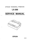
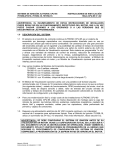
1.0 ALTRONIC V IGNITION SYSTEM - DESCRIPTION
Altronic V is an alternator powered, electronic ignition system. All electronic parts are mounted to the back cover
which disconnects as a module from the alternator section.
The alternator (A) provides the power to charge energy storage capacitor (8). A separate pickup coil (C) and SCA
(D) are used for each of the system's outputs which correspond usually to each engine cylinder. A rotating timer arm
(E) driven through speed reducing gears (F) passes over the pickup coils to trigger on the SCA switches in sequence.
This releases the capacitor's stored energy to the ignition coils which step up the voltage to fire the spark plugs.
CROSS SECTIONAL VIEW - ALTRONIC V UNIT
D - SCA electronic switch
E - Timer arm
F - Distribution gears
A - Alternator
8 - Energy storage capacitor
C - Pickup coil
-3-
41
42
I
\
~.-"1\
-@J--1!!!!!!!!I!!I!!!Iiiii1!!Il;[)
7-711&71
]5 ]7 12 19
\
\
40
]3]9
,I,J,
~ - - ( [ ) -~ aDlDI@
/
""'~"
4S/ 27b
,~4]
-~alll!I@
~- ))!!l1!mn1!~---@--tl!lfl!)))!l)))II))))!lll)j))I))I)) :I)
\
]1
/
\
!
J·j]4
41
44
14
10
/
160
I
15
\ \
16b
\
(biIDi
40
~1@J I·
~
170.
/
17b
13
~~
/ ! I
II
12
I]
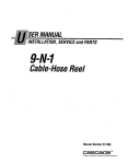
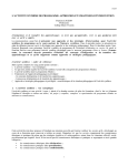
2.0 PARTS IDENTIFICATION AND SPECIFICATION
2.1
PARTS LIST - ALTRONIC V - Reference the exploded view on page 4.
REF. NO.
1
1a
3
4
4a
5
6
7
8
9
10
11
12
13
14
15
16a
16b
16c
17a
17b
18
19
20
21
25
26
26a
26b
PART NO.
510 454-U
510699
902478
410063
510654
560 004-1
560 004-2
560 004-3
560 004-4
560 004-5
510541
502134
502168
902520
160 001
410039
571 003
310518
510357
510359
510625
901 326
900 944
902465
510462
410038
902585
901 010
902586
902487
902503
410045
902541
900996
570017-1
570017-2
570017-3
570017-6
902564
570401
570402
570403
570404
570405
570406
See po. 12
570008
570009
570015
570025
570026
570027
DESCRIPTION
Coupling, yellow
Coupling (109-8912 only)
Spring pin 2-1/8" Ig.
Bearina-shaft (-A -AM -D)
Bearing-shaft (-AW,-GVW)
Housing (-A -AM -AW)
Housing (-GV,-GVW)
Housina (-D)
Housina (-GVC)
Housing (109-8912)
Ventilator
Nameplate - 2.0" X 1.9"
Nameplate - 3.5" X 1.1"
Drive pin
Magnet-rotor
Gasket
Stator
Drive aear 1.5:1
Drive gear 2:1
Drive gear 3:1
Drive gear 1:1
Washer
Lockwasher #8
Screw 8-32
O-ring
Spacer
Screw 5/16"-18
Lockwasher 5/16"
Washer
Snap ring
Washer
Spacer
Screw 8-32
Lockwasher #4
Driven gear ass'y. 1: 1
Driven gear ass'y. 2:1
Driven gear ass'y. 3: 1
Driven gear ass'y. 1.5:1
Screw 4-40
Pickup plate ass'y. 1A
Pickup plate ass'y. 2A
Pickup plate ass'y. 3A
Pickup plate ass'y. 4A
Pickup plate ass'y. 5A
Pickup plate ass'y. 6A
Pickup coil ass'y.
Plate-core ass'y. 2A
Plate-core ass'y. 3A
Plate-core ass'y. 1A
Plate-core ass'y. 4A
Plate-core ass'y. 5A
Plate-core ass'y. 6A
-5-
REF NO
26c
26d
26e
26f
27
27a
27b
27c
29
30
31
31a
31b
32
33
34
35
37
38
39
40
41
42
43
44
45
47
*
*
*
*
PART NO
570010
570011
570012
570020
570021
570022
510627
510651
902574
610117
See pg. 6
301 208-2
301 233-3
504161
583 007
501 335
501 368
510597
570005
570028
570029-1
570029-2
410058
510660
902459
902602
902565
902591
302106
502142
310365
902058
901 004
902567
902587
902064
902483
902645
902579
562001
501 369
900966
902525
DESCRIPTION
Plate-bushing ass'y. 3A
Plate-bushing ass'y. 2A
Plate-bushing ass'y. 1A
Plate-bushina ass'y. 4A
Plate-bushing ass'y. 5A
Plate-bushing ass'y. 6A
Spacer - 1A, 2A, 3A
Spacer-4A,5A,6A
Screw 6-32
Snap ring
Circuit board assembly
Zener diode (10M120Z5)
Zener diode (10M150Z5)
Nut 10-32, zener diode
Plug assembly
Gasket, 5-pin connector
Gasket, 7-pin connector
Spacer
Rear cover, 5-pin conn.
Rear cover, 7-pin conn.
Rear cover, 5-pin w/timing
Rear cover, 7-pin w/timing
Bearing_
Shaft, driven
Nut 6-32
Washer
Screw 6-32
Washer
Timing label, shaft
Timing label, cover
Cover plate
Screw 6-32
Lockwasher
Screw 10-24 X 1.25"
Screw 10-24 X 2.0"
Screw 6-32
Screw 10-24
Washer, sealina
Washer, shim
Connector assembly
Gasket
Lockwasher
Screw 4-40
* Parts for units with electronic timing option (not
illustrated).
NOTE: Reference numbers with a letter suffix are
part of the assembly of the same number
withoutthe suffix. Example: (1 a) is part of (1).
NOTE: It is recommended that 581 40x circuit boards be updated (exchanged) for the 572 61 x series.
UNIT NO.
BACK COVER
CIRCUIT BOARD ASS'Y. (27)
1A18
581 401-1
572 612
1A28
581 401-2
572 612
1A28H
581401-2H
572 612H
2A14
581 404-1
572 613
2A18H
581 402-2H
572 612H
2A25
581 404-3
572 613
2A28
581 402-1
572 612
2A28H
581 402-1H
572 612H
2A64
581 404-2
572 613
3A14
581 406-2
572 613
3A25
581 406-4
572 613
3A35
581 406-3
572 613
3A64
581 406-1
572 613
4A24
581 407-1
572 614
4A34
581 407-2
572 614
5A24
581 405-1
572 616
6A24
581 408-2
572 616
6A34
581 408-1
572 616
61-2611*
581 407-2
572 614 (Follow testinQ for 4A34)
328-8382*
581 407-2
572 614 (Follow testing for 4A34)
9Y-6465*
581 408-1
572 616 (Follow testing for 6A34)
109-8912*
581 408-2
572 616 (Follow testing for 6A24)
* Caterpillar OEM units.
3.0 PERFORMANCE SPECIFICATIONS:
A. Install unit on a test stand equipped with a suitable number of 501 061 coils and spark gaps. Test stand wiring
should conform to that shown in the Installation Instructions form AV II for 6-cylinder engines.
3.1 VOLTAGE TEST
A. With the wiring harness unplugged, measure the positive voltage at the connector "G" pin:
UNIT SPEED
500 rpm
CIRCUIT BOARD NO.
CONNECTOR PIN
VOLTAGE OUTPUT
"G"
"G"
111-129 VDC
140-160 VDC
140-160 VDC
140-160 VDC
140-160 VDC
"E..
"E"
IIEII
572 602, 572 612
572 602H, 572 612H
572 603, 572 613
572 604 572 614
572 606, 572 616
3.2 OPERATING TEST
A. At 50 rpm of the back cover a 7mm gap should fire consistently.
B. At the TEST RPM, a 15mm gap should fire consistently.
3.3 TIMING SPECIFICATIONS
A. Timing should be as specified in the table below as measured on a standard ignition test stand with the degree
wheel indicator rotating at the unit coupling speed.
B. If timing is out of specification, change the pick-up coil (31) in question.
*
UNIT NO.
COUPLING
TEST RPM
1A18
1A28
1A28H
2A14
2A18H
2A25
2A28
2A28H
2A64
1,300
1,300
1,300
2,000
700
2,400
1,300
1,300
3,000
3A14
3A25
3A35
3A64
2,000
2,000
3,000
3,000
4A24
4A34
5A24
6A24
6A34
2,000
3,000
2,000
2,000
3,000
COUPLING
ROTATION
15-17 degree retard at low speed.
cw
cw
cw
cw
cw
cw
cw
cw
cw
cw
cw
cw
cw
cw
cw
cw
cw
ccw
FIRING SEQUENCE DEGREES
B
C
D
E
F
A
O*
O**
O**
0
0
0
0
0
0
180
0
0
0
0
180
0
0
0
0
0
180
180
0
0
0
90
270
120
240
0
0
180
180
270
144
120
180
** 30-34 degree retard at low speed.
-7-
TOLERANCE + /-
-
2
2
2
2
2
3
240
120
0
0
180
0
180
288
240
0
2
2
3
3
180
90
72
0
180
216
120
0
240
180
2
3
2
2
3
4.0 TROUBLESHOOTING
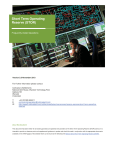
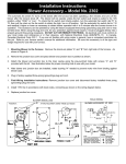
4.1 CIRCUIT DIAGRAM
A. The diagram below shows the Altronic V circuit for one cylinder. Each component in the Timing-Distribution
section (to the right of the dashed line) is present in a quantity equal to the number of system outputs; each
output requires a pick-up coil assembly, capacitor C3 and power SCR2.
B. The operation is as follows: The AC voltage generated by the alternator is converted to DC by diodes D1 and
stored in the energy storage capacitor C1. The DC voltage level is regulated by zener diode Z. Capacitor C2 is
charged through resistor R1 to provide the energy to trigger power SCR2. This occurs when the rotating
distributor arm passes a pick-up coil (P) triggering on SCR1 and connecting capacitor C2 through resistor R3
to the gate of SCR2. SCR2 then turns on discharging capacitor C1 into the primary of the ignition coil which
steps up the voltage to fire the spark plug. Capacitor C3 acts as a filter to prevent crossfiring between outputs.
R5
'E'
v-~---------------------------------------o
D2
D2
D2
SCP2
,--------,
I
I
I
TO
SPARK
PLUG
P
P4
"A, R C'
)
+
R2
R3
z
I
L
Cl
SCPl
___________
C2
-.l
TO
SPARK
PLUG
C3
"D'
C. Components:
Capacitor, energy storage
C1
C2
C3
D1
D2
SCR1,P,R2,R3
SCR2
R1
R4
Capacitor, trigger
Capacitor, filter
Diode
Diode, dual
R5
D3
Diode, blocking_
Z
-8-
Pick-up coil assembly
Power SCR
Resistor, trigger circuit
Resistor, SCR J]8te
Resistor
Zener diode
4.2 OSCILLOSCOPE TESTING - The system should be fully connected per section 3.0 with the Altronic V unit
operating at the TEST RPM given in section 3.3. Connect the oscilloscope probe to the shutdown lead of the
output connector - "E" for the 5-pin connector or "G" for the 7-pin connector. Set the oscilloscope vertical
calibration to 50 volts/dlv.; adjust the time base to get a full cycle of firings on the screen: No. of discharges =
number of outputs for the unit.
A. STORAGE CAPACITOR PATIERN: NORMAL - The normal patterns for typical 3-output (3A64) and 6-output
(6A34) units are shown below.
3-0UTPUT UNIT - 3A64
6-0UTPUT UNIT - 6A34
200V,
lOOV,
OV,
~/
/
~
V
/
/:
I
/
I
200V,
,
/
I
/
~
I
/
/
/
/
),
I
I
I
/
/
t
II
¥ )
j
I
lOOV,
OV,
B. STORAGE CAPACITOR PATIERN: ABNORMAL - One cylinder misfiring. See troubleshooting section 4.4.
3-0UTPUT UNIT - 3A64
6-0UTPUT UNIT - 6A34
200V,
200V,
lOOV,
OV,
L
V
v
v
)'
L
~
V
1/
)
I 'I
V
l
I
t
,;
V
/
l
)
I
lOOV,
OV,
C. STORAGE CAPACITOR PATIERN: ABNORMAL - Irregular waveform. See troubleshooting section 4.5.
3-0UTPUT UNIT - 3A64
6-0UTPUT UNIT -6A34
200V,
200V,
r-
lOOV,
, V
,-
OV,
..L
,. J
V
r
r-
f0-
L
~
,J
1.
-9-
J
j
r:
V
,
r
J ,.1
,J
V
r
J
j
lOOV,
OV,
4.3 PROCEDURE
A. See section 3.0-3.3 for proper performance.
B. Use Simpson model 260 meter on RX10,000 scale unless otherwise specified.
C. First discharge all capacitors. Carefully use a screwdriver to short from the connector shell first to the "E" pin on
5-pin connector or "G" pin on 7-pin connector, then to all other pins.
4.4 ONE OUTPUT DOES NOT FIRE
A. Check that the 2-lead pickup coil connector is fully plugged into the circuit board receptacle.
B. Check with ohmmeter as follows: Positive lead to case; negative lead to connector pin with no output. Move
the timer arm (21 a) past the pickup coil corresponding to the test connector pin ("A" is red; "B", "C", etc. follow
in a CW direction from "A"); meter should pulse indicating pickup coil output. If not, replace pickup coil assembly
(26a) - see section 6.2.
C. If above tests are OK, replace circuit board assembly (27) - see section 6.1.
4.5 SYSTEM HAS WEAK OR NO OUTPUT
A. Check stator (9) resistance - replace if defective - see section 5.0.
1. Center pin to outer pin:
450-650 ohms (RX100 scale)
2. Center pin to other outer pin: 5000-6000 ohms
3. Center pin to lamination core: infinite
5.0 SERVICE - ALTERNATOR SECTION
A. The unit breaks down into two major parts: the Alternator Section and the Back Cover Assembly. Remove the
four back cover attaching screws (42), (44) and carefully pull the back cover assembly away from the alternator
housing; unplug the 3-prong internal connector.
B. The procedures of this section require the use of an arbor press.
5.1 DISASSEMBLY
A. Remove the phenolic spacer (15), O-ring (14) and stator (9) from the alternator housing.
B. -AW/-GVW UNITS ONLY: Remove hardware (16a), (16b), (16c) or (17a), (17b) and sleeve (18) from unit shaft.
C. Drive spring pin (1 a) out of coupling (1) and shaft and remove coupling.
D. Remove screw (13), lockwasher (12), washer (11) and drive gear (10).
E. If it is necessary to replace bearing-shaft (3), support the housing on the coupling end and press shaft out of the
magnet-rotor assembly and housing.
F. Wrap magnet-rotor assembly (7) in a cloth or paper to keep it clean.
5.2 PARTS REPLACEMENT
A. Replace gasket (8).
B. Replace coupling (1) and bearings (3) and (31 a) with new parts.
C. Replace any removed hardware with new parts.
D. Aluminum housings should be cleaned with carbon tetrochloride or similar cleaning solution.
E. Any metal filings should be cleaned from magnet-rotor (7) before reassembly.
-10 -
5.3 REASSEMBLY - ALTERNATOR SECTION
A. Press new bearing-shaft (3) into housing (4) until it bottoms against shoulder. Housing (4) should be supported
behind the internal shoulder with tool no. 506 101 B. Push on the outer race of the bearing using tool 506 101 A.
B. Clean all debris from the magnet-rotor assembly (7).
C. Slide magnet-rotor assembly (7) over shaft with plate facing out as shown below. Support the shaft on the
coupling end using tool no. 506 102B and, using tool no. 506 102C, press magnet-rotor assembly (7) on the shaft
0.575" past the shoulder for the drive gear.
D. Slide coupling (1) onto the shaft and secure with spring pin (1a) through the coupling and shaft.
E. -AW/-GVW UNITS ONLY: Install sleeve (18) and engine gear. Secure with hardware (16a), (16b), (16c) or (17a).
(17b) - see page 4.
F. Inspect gear (10); replace if worn. Secure with new hardware (11), (12), and (13).
G. Reinstall stator with leads at the 6 o'clock position, a new O-ring (14) and spacer (15).
HDUS1NG (4)
CDUPLlNG (1)
SLEEVE
()8)\
,-
--
,1---II
II
II
LI- __ _
MAGNET-ROTOR (7)
-11 -
6.0 SERVICE - BACK COVER ASSEMBLY
A. Replace only those parts requiring service.
6.1 CIRCUIT BOARD ASSEMBLY (27) - REPLACEMENT
A. Use a small screwdriver to pull the circuit board receptacle levers away from the 2-lead housing of the pickup
coil connectors; then unplug the pickup connectors from the circuit board (27).
B. Remove four screws (43), zener diode nut (27b) and washer (45), screw (34), washer (33) and nut (32). The
circuit board can then be removed from the cover. Keep track of spacer (30).
C. Reverse steps 5.1 A and 5.1 B to reassemble.
NOTE: Use new parts for washers (33) and (45) - see page 5.
6.2 PICKUP COIL ASSEMBLY (268) - REPLACEMENT
A. Remove hardware (19), (12), (11) holding the driven gear/magnet arm assembly. Pull driven gear/magnet-arm
assembly (21) from the driven shaft.
B. Unplug the pickup coil connector in question - see 6.1 A.
C. To replace a pickup coil (26a) , remove three screws (26e) and plate assembly (26c). On 1-cylinder units only,
remove the small snap ring (26f). Then remove the pickup coil in question.
D. When installing the new pickup coil, the end with the marked line must face out against plate (26C). Rotate the
coil body so that the bulge does NOT face inside the circle of the O.D. of the bearing (31 a) - see orientation as
shown below.
E. To reinstall top plate (26c), insert screws (26e) through plate (26c) and spacers (26d) intothe plate-core assembly
(26b); then tighten screws (26e).
F. Plug the pickup coil connector into the circuit board receptacle.
570 401 CIA)
570 402 (2A)
A
o
A-55! 002-1
570 404 C4A)
A B -
570 403 C3A)
A
0
551 002-4
551 002-4
A-55! 002-)
B - 55) 002-2
C - 55) 002-3
570 405 (SA)
570 406 (6A)
A
A
B
C
D
-
551
551
551
551
002-5
002-4
002-4
002-2
D
A-55!
B - 55!
C - 551
D - 55)
E - 55!
002-)
002-2
002-2
002-4
002-2
-12 -
A,E,r- B -
C D -
551
551
551
551
002-5
002-1
002-2
002-3
6.3 DRIVEN GEAR/MAGNET ARM ASSEMBLY (21)
NOTE: Early-production assemblies having the driven gear held to the magnet-arm with slotted pan-head screws
should be updated to the equivalent one-piece driven gear/magnet-arm assembly (21).
A. Remove screw (19) and pull driven gear/magnet-arm assembly (21) from shaft (31 b). DO NOT loosen the three
small button-head, hex-socket screws holding the gear assembly together. Keep track of shim washers (47).
6.4 DRIVEN SHAFT (31b), BEARING (31.)
NOTE: It is recommended that all units be updated to the current design press-fit secured driven shaft (31 b).
A. The procedures of this section require the use of a small arbor press.
B. Remove the driven gear assembly (21) per section 6.3.
C. Unplug the pickup coU connectors - see step 6.1 A.
D. Remove three screws (25) and lockwashers (20). Then pull the entire pickup plate assembly (26) off bearing
(31 a).
E. Remove cover plate (39) and timing decal (37).
- SNAP-RING SECURED DRIVEN SHAFT - Remove snap ring and pull driven shaft assembly from bearing (31a).
- PRESS-FIT SECURED DRIVEN SHAFT - Press shaft (31 b) out of bearing (31 a).
F. Press bearing (31a) out of rear housing (31).
G. Support housing (31) with tool 506 103B; slide bearing (31 a) over guide of tool no. 506 103B and press bearing
into housing with tool no. 506 103A until it bottoms.
H. Support bearing (31 a) on the inner race with tool 506 104B and press, using tool 506 104A, on the gear shoulder
of shaft (31 b) until the shaft bottoms against bearing.
6.5 REASSEMBLY - DRIVEN SHAFT ASSEMBLY
A. Reinstall the pickup plate assembly (26) and secure with hardware (20) and (25).
B. Plug the pickup connectors into the circuit board receptacles.
C. Slip shims (47) - the same number as removed, if any - over the end of shaft (31 b) against shoulder.
D. Check that the air gap between the rotating arm and the plate (26c) is .005"-.018". If the air gap requires
adjustment, first remove screw (19) holding the driven gear and pull the assembly (21) from the shaft. Add or
subtract a shim washer (47) to increase or decrease the air gap. Reinstall assembly (21 ) and secure with hardware
(11), (12) and (19).
E. Using a small brush, apply a thin coat of silicone compound (GC type 5Z; Altronic part no. 503 259) to the teeth
of the driven gear (21).
F. Install washer (35), timing decal (37), lockwasher (12) and screw (19) but tighten screw so that the lockwasher
just starts to compress.
G. Place the timing arm (21) centered on the red pickup coil core. The red mark on decal (37) should be placed
midway between the CCW and CW marks of the label. Tighten screw (19).
H. Install cover plate (39) and secure with two screws (40).
-13-
6.6 REASSEMBLY - BACK COVER TO ALTERNATOR SECTION
A. Set the back cover assembly with the timing mark aligned to either CCW or CW as required for the application.
Set the alternator coupling angle as shown in the chart below.
B. Mate the back cover to the alternator keeping the alignment of the back cover timing mark and alternator coupling
as set in step 6.6A.
C. Secure the back cover to the alternator keeping the alignment of the back cover timing mark to the alternator
with hardware (41), (42) and (44).
BACK COYER
TIMING INDICA TOR
UNIT NO
COUPLING ANGLE
CCW
CW
1A18-GV
00
-
1A28-A
-
70 0
00
70 0
2A14-AW,GVW
-
70 0
2A14-0
-
00
2A18H-GV
-
70 0
2A25-A
70 0
2A28-AGV
-
2A64-GVW
-
70 0
3A14-A GV
0
0
70 0
3A14-0
-
00
0
-
2A14-A,GV
70 0
3A25-GV
0
3A35-A
-
70 0
3A64-AGV
00
70 0
3A64-AM
-
45 0
3A64-AW,GVW
70 0
0
70 0
4A24-AWGVW
-
70 0
4A24-0
-
00
4A34-GVW
-
70 0
5A24-GV
00
-
6A24-0
-
00
4A24-A,GV
0
0
-
0
70 0
-
450
0
0
9Y-6465
0
0
109-8912
00
-
6A24-GV
6A34-AGV
6A34-AM
6A34-AWGVW
6A34-GVC
61-2611
0
0
CJ
70 0
70 0
-14-
7.0 SERVICE - ASSEMBLY TOOLS
A. The following assembly tools are referred to in sections 5.3 and 6.4.
506 101A Press bearing-shaft (3) into housing (4)
506 101B Support housing (4)
506 102B Support shaft (3)
506 102C Press magnet·rotor assembly (7) on bearing-shaft (3)
506103A Press bearing (31a) into cover housing (31)
506 103B Support cover housing (31) and bearing (31a)
506104A Press shaft (31 b) into bearing (31a)
5061048 Support bearing (31 b)
8.0 OPERATIONAL TEST
A. Perform the tests following the guidelines of sections 3.0 through 3.3.
B. Run the Operating Test of section 3.28. for one hour.
C. After the one hour Operating Test, check timing per section 3.3.
-15 -