1
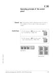
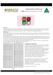
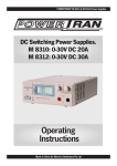
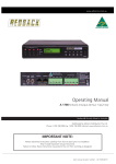
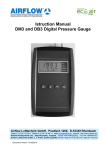
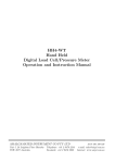
www.altronics.com.au
Operating Manual
A 4370 125 Watt Power Amplifier
A 4380 250 Watt Power Amplifier
OVERVIEW
These Redback 125W and 250W power amplifiers are ideal for installations requiring high power zone amplifiers. Ideally
suited for use in shopping centres, pedestrian precincts, public transport facilities and convention centres.
FEATURES
• Robust design incorporating latest Mosfet technology
• Very Low noise and distortion
• 70V, 100V and 4-16Ω outputs
• 240V AC or 24V DC operation
• 24V DC @ 1 Amp output for external devices
• Multi stage thermally cued fan cooling
• Output Peak Limited
• Thermal Overload protected
• Signal Presence Indicators
• Fault Indicators
• Power Status Indicators
• Rack Mountable (suits 19 inch racks)
POWER SUPPLY
The amplifier operates on 230V AC or 24V DC primarily for battery backup operation. Ensure power is switched OFF at
the front panel before connecting either mains power to the IEC socket or 24V DC to the screw terminal input. (see Fig 2
for more details) As high currents may be drawn when operating from a 24V DC supply confirm the capacity of the DC
power supply used.
AUDIO CONNECTIONS
Audio input is via a 3 pin XLR socket on the rear of the amplifier. This is a 500mV line level balanced signal which is
normally fed from from a mixer panel. Pinout details are printed on the rear of the amplifier. A balanced Line Out XLR
socket is also provided on the rear of the amplifer for passing the audio signal on to more slave amplifiers if required. The
amplifier output level control is also rear mounted to prevent tampering or accidental adjustment (see Fig 2 for more
details).
Redback® Proudly Made In Australia
User manual revision number: 1.0 30/10/2014
SPEAKER CONNECTIONS
Speakers with a total impedance or 4-16Ω may be connected to the terminals marked 4-16Ω on the rear of the amplifier.
Speakers fitted with line transformers (either 70V or 100V) may be connected to the corresponding terminals on the rear
of the amplifer. Always ensure the total load of the fitted speakers does not exceed the rated output of the amplifier
otherwise damage may result. When fitting speakers with line transformers the impedance of the load cannot be
measured using a standard multimeter. An impedance meter is required. Fig 1 lists the impedance at certain loads of
speakers fitted with 70V and 100V line transformers. So for a total load of 250 watts using 100V line transformer fitted
speakers the impedance of the speaker load should be 40Ω.
i
About 70V & 100V Line Speaker Systems
Wiring speakers in parallel for 70/100V line: Where several speakers are to
be used at one time, on one circuit, it becomes necessary to use speakers fitted
with line-matching transformers. This is to overcome the effects of connecting
speakers in parallel and cable losses. The amplifier generally has an output
voltage of 100 volts (70 volts is typically used in North America, however
operation is similar). In this configuration the total wattage load on the amplifier
is derived from adding all the line transformer primary tap ratings together. For
example, 70 one watt speakers will have a total speaker load of 70 watts. Or
alternatively, it is conceivable to connect 100 one watt speakers to a 100 watt,
100 volt line amplifier.
Measuring 70/100V Line Speaker Impedance: To measure amplifier system
load, you must use an impedance meter in order to measure the ac resistance
of the connected speaker network. Impedance cannot be measured with a
standard multimeter, as this measures the dc resistance. Use the Altronics
Q 2001 or similar impedance meter.
Load
0.5W
0.66W
1W
1.25W
2W
2.5W
3W
5W
7.5W
10W
15W
20W
30W
40W
60W
100W
125W
250W
500W
70V
9.4kΩ
7.12kΩ
4.7kΩ
3.76kΩ
2.35kΩ
1.88kΩ
1.56kΩ
940Ω
626Ω
470Ω
313Ω
235Ω
156Ω
117Ω
78Ω
47Ω
37Ω
19Ω
9.4Ω
100V
20kΩ
15kΩ
10kΩ
8kΩ
5kΩ
4kΩ
3.3kΩ
2kΩ
1.3kΩ
1kΩ
666Ω
500Ω
333Ω
250Ω
166Ω
100Ω
80Ω
40Ω
20Ω
Fig 1
24V DC OUTPUT
A constant 24V output terminal has been provided to power ancilliary 24V devices (see Fig 2 for more details). The ouput
has a maximum current draw of 1 amp. If more than 1 amp is drawn from the output, internal polyswitches will
disconnect the output. These will reset once the current draw is reduced.
TROUBLE SHOOTING
If the REDBACK Phase 4 amplifier fails to deliver the rated performance, check the following:
No Power, No Lights
Make sure amplifier power switch is on. Make sure mains power switch is on at the wall. Check the mains and DC fuse. Replace with only the correct type and rating. Over rated fuses with invalidate warranty.
Distorted Output
Check that the speaker type is correct for the output that you are using (ie. 4-16Ω, 70V or 100V line). Check for any short circuits on the speaker line.
Very Low Output Volume
Make sure that the input is the correct level (check for shorted connectors). Check for any short circuits on the speaker line.
Check if signal LED on the front panel is lit to indicate there is signal. If it is not lit there is no signal present.
Continually Blows Fuses
Make sure that the speaker line is not shorted. Check speaker types, ratings and if on correct output.
Amplifier Keeps on Cutting In & Out
Make sure that there is adequate ventilation around the amplifier. Check the vent slots on the front,top and sides are not covered or blocked and the fan on the rear is functioning correctly. Check also speaker types, ratings and for any short circuits on the speaker line.
No Output From 24V DC
Make sure the
2 Redback® Proudly Made In Australia
www.altronics.com.au
Fig 2 shows a typical install where the A 4370 amplifiers are used as slave amplifiers with the audio output from the
mixer amplifier passed through each slave amplifier.
MIXER AMPLIFIER
Phantom Power Input 5
Phantom Power Input 4
Phantom Power Input 3
Phantom Power Input 2
Phantom Power Input 1
3
4
Pre or Post Master.
–
OUTPUTS
70V
–
Not Used
Not Used
SW
Item
On
Off
1 Input 2 Level 1V 100mV
2 Input 2 Priority
On Off
3 Input 1 Priority
On Off
4 Input 1 Level 1V 100mV
Voice Chime Alert
Over
& Evac
DIP 2
SW
Item
On
Off
1 Input 4 Level 1V 100mV
2
Not USed
3 Input 3 Priority On Off
4 Input 3 Level 1V 100mV
*
IMPORTANT NOTE
Triggers
ALERT - EVAC MODULE
Output Levels
**
EV
Power Fail
(Contacts
close on
power fail)
–
Input 5
Input 4
Input 3
Input 2
Balanced Mic
Balanced Mic
Balanced Mic
Balanced Mic
Balanced Mic
2
2
3
4
5
1
6
7
L
R
+
230V AC @ 50Hz
–
Interface
2
3
DIP 44
DIP
1
2
3
1
2
3
1
2
1
3
2
3
Input 1
Balanced Mic
1
2
1
3
3
8
24V DC
Switched
Output
1
RESETTABLE
DC FUSE
2
3
Ensure power is switched OFF when
adjusting DIP switches. New
settings will be effective when
power is switched back on.
4 -16Ω
Input 6
Balanced Line
DIP 5
1
PTT
Rem. Vol
Connect (short to
to 1KΩ Pot activate)
CH CAN COM
AL
Preamp Out
Send
Phantom Power Input 6
Item
On
Off
Off SW
Off 1 Input 6 Level 1V 100mV
Not USed
Post 2
Not USed
Off 3
4 Input 5 Level 1V 100mV
Off
Off
DIP 4
Off SW
Item
On Off
Not Used
Off 1
Not Used
Off 2
On
On
Pre
On
On
On
On
On
On
† Sets the Preamplifier output to
100V
+
Preamp Out †
Return
Made in Australia
by Altronic
Distributors
Pty Ltd
Item
Switched 24VDC Out
+
AC Fuse Ratings
Model 125W 250W
AC Fuse 5A 7.5A
SW
1
2
3
4
5
6
7
8
DIP 1
DIP 3
DIP 5
*
Priority or VOX muting is only
functional on inputs 1-3. When
VOX is enabled on input 1 it will
override all other inputs including the Alert/Evac Module. VOX
enabled on input 2 will override
inputs 3-6. VOX enabled on input
3 will override inputs 4-6.
If the Alert/Evac module is fitted
it will override inputs 2-6.
+
www.altronics.com.au
!
+ _
CAUTION
RISK OF ELECTRIC SHOCK
OPEN BY QUALIFIED
PERSONNEL ONLY
L
L
DIP 3
R
1
4
Line
Tape Out
2
3
L
R
L
DIP 2
R
4
1
Line
2
3
L
R
L
DIP 1
R
1
4
Line
Line
2
3
R
4
Line
Line
Link To Charge
24V DC IN Backup battery
Speakers fitted with
100V line transformers.
A 4370 AMPLIFIER
MODEL AC FUSE
1
5A
7.5A
4 -16Ω
INPUT
24V DC
Made in Australia by
Altronic Distributors Pty Ltd
24V DC
OUT
(1A Max)
4
6
0
10
–
+
–
+
+
–
2
2
1
3
LINE IN
1
2
1
3
8
2
–
LINE OUT
VOLUME
www.altronics.com.au
+
CAUTION
RISK OF ELECTRIC SHOCK
OPEN BY QUALIFIED
PERSONNEL ONLY
230V AC @ 50Hz
70V
100V
1 • Shield
2 • Hot
3 • Cold
2
3
OUTPUTS
!
A 4370
A 4380
3
+ _
RESETTABLE
FUSE
+
-
SLAVE AMPLIFIER
MODEL AC FUSE
1
5A
7.5A
4 -16Ω
INPUT
24V DC
Made in Australia by
Altronic Distributors Pty Ltd
24V DC
OUT
(1A Max)
–
+
–
–
+
–
LINE OUT
VOLUME
4
6
0
10
2
2
1
3
LINE IN
1
2
1
3
8
2
+
230V AC @ 50Hz
70V
www.altronics.com.au
+
CAUTION
RISK OF ELECTRIC SHOCK
OPEN BY QUALIFIED
PERSONNEL ONLY
100V
1 • Shield
2 • Hot
3 • Cold
2
3
OUTPUTS
!
A 4370
A 4380
3
+ _
RESETTABLE
FUSE
SLAVE AMPLIFIER
MODEL AC FUSE
1
5A
7.5A
70V
4 -16Ω
INPUT
24V DC
Made in Australia by
Altronic Distributors Pty Ltd
24V DC
OUT
(1A Max)
4
6
0
–
+
–
+
+
–
2
8
2
–
LINE OUT
VOLUME
www.altronics.com.au
+
CAUTION
RISK OF ELECTRIC SHOCK
OPEN BY QUALIFIED
PERSONNEL ONLY
230V AC @ 50Hz
100V
1 • Shield
2 • Hot
3 • Cold
2
3
OUTPUTS
!
A 4370
A 4380
1
3
2
1
3
LINE IN
2
1
3
10
+ _
RESETTABLE
FUSE
Fig 2
www.altronics.com.au
Redback® Proudly Made In Australia
3
SPECIFICATIONS Measurements referenced to 1kHz.
Power output:
A 4370- 125 W RMS,A 4380-250W RMS
Distortion:
< 0.5%, @ 1kHz
Frequency response:50Hz - 15kHz, -3dB
Output line:
100V, 70V, or 4 - 16Ω
Signal to noise ratio: (peak limiting by-passed) > 90 dB
Line output:
600Ω balanced, 0dBV, 3 pin XLR
Speaker connection: Screw terminals
24V DC output:
Screw terminals
Inputs:
3 pin XLR (500mV)
24V-30V dc power: Screw terminals
240V ac power:
IEC power connector
Indicators:
Mains, 24V dc, Power, Signal presence,
Over temp, Over current, Shut down, Peak limiting
Current Draw:
Current Draw:
Power supply:
Protection:
A 4370 - 250mA Standby, 8A Full @ 24V dc
A 4380 - 250mA Standby, 17A Full @ 24V dc
240V ac or 24V dc (nominal)
A 4370 - 5A ac and 10A dc fuse
A 4380 - 7.5A ac and 20A dc fuse
Dimensions:
≈ 483W x 340D x 88H
*Specifications subject to change without notice
REDBACK is a registered trademark of Altronic Distributors Pty Ltd
Since 1976 Redback amplifiers have been manufactured in Perth, Western Australia by Altronics. With over 35 years
experience in the commercial audio industry, we offer consultants, installers and end users reliable products of high build
quality with local product support. We believe there is significant added value for customers when purchasing an
Australian made Redback amplifier or PA product
Australian Made Status
All Redback house products made by Altronics will now be sporting the official Australian Made logo. Since starting manufacturing of commercial audio equipment in the mid 70’s we have always taken pride in producing a quality local product.
The new adoption of the Australian Made logo will help us get the word out to local and export markets that our
products carry the official compliance seal of the Australian Made campaign. We have always pushed our ‘local is better’
line in all of our marketing efforts, it’s always an added boost when you are backed up by a widely recognised and
respected icon.
Industry leading 10 year warranty.
There’s a reason we have the industry leading DECADE warranty. It’s because of a long tried and tested history of bulletproof reliability. We’ve heard PA contractors tell us they still see the original Redford amplifier still in service in schools that’s over 37 years of operation - and still going strong!
Should a product become faulty please contact us to obtain a return authorisation number. Please ensure you have all the
relevant documentation on hand. We do not accept unauthorised returns. Proof of purchase is required so please retain
your invoice.
Distributed by Altronic Distributors Pty. Ltd.
Phone: 1300 780 999 Fax: 1300 790 999 Internet: www.altronics.com.au
4 Redback® Proudly Made In Australia
www.altronics.com.au